EP4467364A1 - Corner module apparatus - Google Patents
Corner module apparatus Download PDFInfo
- Publication number
- EP4467364A1 EP4467364A1 EP23192938.1A EP23192938A EP4467364A1 EP 4467364 A1 EP4467364 A1 EP 4467364A1 EP 23192938 A EP23192938 A EP 23192938A EP 4467364 A1 EP4467364 A1 EP 4467364A1
- Authority
- EP
- European Patent Office
- Prior art keywords
- steering
- transmission
- transmission link
- corner module
- module apparatus
- Prior art date
- Legal status (The legal status is an assumption and is not a legal conclusion. Google has not performed a legal analysis and makes no representation as to the accuracy of the status listed.)
- Granted
Links
Images









Classifications
-
- B—PERFORMING OPERATIONS; TRANSPORTING
- B62—LAND VEHICLES FOR TRAVELLING OTHERWISE THAN ON RAILS
- B62D—MOTOR VEHICLES; TRAILERS
- B62D7/00—Steering linkage; Stub axles or their mountings
- B62D7/06—Steering linkage; Stub axles or their mountings for individually-pivoted wheels, e.g. on king-pins
-
- B—PERFORMING OPERATIONS; TRANSPORTING
- B62—LAND VEHICLES FOR TRAVELLING OTHERWISE THAN ON RAILS
- B62D—MOTOR VEHICLES; TRAILERS
- B62D5/00—Power-assisted or power-driven steering
- B62D5/04—Power-assisted or power-driven steering electrical, e.g. using an electric servo-motor connected to, or forming part of, the steering gear
- B62D5/0418—Electric motor acting on road wheel carriers
-
- B—PERFORMING OPERATIONS; TRANSPORTING
- B60—VEHICLES IN GENERAL
- B60K—ARRANGEMENT OR MOUNTING OF PROPULSION UNITS OR OF TRANSMISSIONS IN VEHICLES; ARRANGEMENT OR MOUNTING OF PLURAL DIVERSE PRIME-MOVERS IN VEHICLES; AUXILIARY DRIVES FOR VEHICLES; INSTRUMENTATION OR DASHBOARDS FOR VEHICLES; ARRANGEMENTS IN CONNECTION WITH COOLING, AIR INTAKE, GAS EXHAUST OR FUEL SUPPLY OF PROPULSION UNITS IN VEHICLES
- B60K7/00—Disposition of motor in, or adjacent to, traction wheel
- B60K7/0007—Disposition of motor in, or adjacent to, traction wheel the motor being electric
-
- B—PERFORMING OPERATIONS; TRANSPORTING
- B60—VEHICLES IN GENERAL
- B60G—VEHICLE SUSPENSION ARRANGEMENTS
- B60G15/00—Resilient suspensions characterised by arrangement, location or type of combined spring and vibration damper, e.g. telescopic type
- B60G15/02—Resilient suspensions characterised by arrangement, location or type of combined spring and vibration damper, e.g. telescopic type having mechanical spring
- B60G15/06—Resilient suspensions characterised by arrangement, location or type of combined spring and vibration damper, e.g. telescopic type having mechanical spring and fluid damper
- B60G15/062—Resilient suspensions characterised by arrangement, location or type of combined spring and vibration damper, e.g. telescopic type having mechanical spring and fluid damper the spring being arranged around the damper
-
- B—PERFORMING OPERATIONS; TRANSPORTING
- B60—VEHICLES IN GENERAL
- B60G—VEHICLE SUSPENSION ARRANGEMENTS
- B60G3/00—Resilient suspensions for a single wheel
- B60G3/02—Resilient suspensions for a single wheel with a single pivoted arm
- B60G3/04—Resilient suspensions for a single wheel with a single pivoted arm the arm being essentially transverse to the longitudinal axis of the vehicle
- B60G3/06—Resilient suspensions for a single wheel with a single pivoted arm the arm being essentially transverse to the longitudinal axis of the vehicle the arm being rigid
-
- B—PERFORMING OPERATIONS; TRANSPORTING
- B60—VEHICLES IN GENERAL
- B60G—VEHICLE SUSPENSION ARRANGEMENTS
- B60G3/00—Resilient suspensions for a single wheel
- B60G3/18—Resilient suspensions for a single wheel with two or more pivoted arms, e.g. parallelogram
- B60G3/20—Resilient suspensions for a single wheel with two or more pivoted arms, e.g. parallelogram all arms being rigid
-
- B—PERFORMING OPERATIONS; TRANSPORTING
- B60—VEHICLES IN GENERAL
- B60G—VEHICLE SUSPENSION ARRANGEMENTS
- B60G3/00—Resilient suspensions for a single wheel
- B60G3/18—Resilient suspensions for a single wheel with two or more pivoted arms, e.g. parallelogram
- B60G3/20—Resilient suspensions for a single wheel with two or more pivoted arms, e.g. parallelogram all arms being rigid
- B60G3/26—Means for maintaining substantially-constant wheel camber during suspension movement ; Means for controlling the variation of the wheel position during suspension movement
-
- B—PERFORMING OPERATIONS; TRANSPORTING
- B60—VEHICLES IN GENERAL
- B60G—VEHICLE SUSPENSION ARRANGEMENTS
- B60G7/00—Pivoted suspension arms; Accessories thereof
- B60G7/001—Suspension arms, e.g. constructional features
-
- B—PERFORMING OPERATIONS; TRANSPORTING
- B60—VEHICLES IN GENERAL
- B60G—VEHICLE SUSPENSION ARRANGEMENTS
- B60G7/00—Pivoted suspension arms; Accessories thereof
- B60G7/005—Ball joints
-
- B—PERFORMING OPERATIONS; TRANSPORTING
- B60—VEHICLES IN GENERAL
- B60G—VEHICLE SUSPENSION ARRANGEMENTS
- B60G7/00—Pivoted suspension arms; Accessories thereof
- B60G7/008—Attaching arms to unsprung part of vehicle
-
- B—PERFORMING OPERATIONS; TRANSPORTING
- B60—VEHICLES IN GENERAL
- B60G—VEHICLE SUSPENSION ARRANGEMENTS
- B60G7/00—Pivoted suspension arms; Accessories thereof
- B60G7/02—Attaching arms to sprung part of vehicle
-
- B—PERFORMING OPERATIONS; TRANSPORTING
- B62—LAND VEHICLES FOR TRAVELLING OTHERWISE THAN ON RAILS
- B62D—MOTOR VEHICLES; TRAILERS
- B62D3/00—Steering gears
- B62D3/02—Steering gears mechanical
-
- B—PERFORMING OPERATIONS; TRANSPORTING
- B62—LAND VEHICLES FOR TRAVELLING OTHERWISE THAN ON RAILS
- B62D—MOTOR VEHICLES; TRAILERS
- B62D5/00—Power-assisted or power-driven steering
- B62D5/001—Mechanical components or aspects of steer-by-wire systems, not otherwise provided for in this maingroup
- B62D5/005—Mechanical components or aspects of steer-by-wire systems, not otherwise provided for in this maingroup means for generating torque on steering wheel or input member, e.g. feedback
- B62D5/006—Mechanical components or aspects of steer-by-wire systems, not otherwise provided for in this maingroup means for generating torque on steering wheel or input member, e.g. feedback power actuated
-
- B—PERFORMING OPERATIONS; TRANSPORTING
- B62—LAND VEHICLES FOR TRAVELLING OTHERWISE THAN ON RAILS
- B62D—MOTOR VEHICLES; TRAILERS
- B62D5/00—Power-assisted or power-driven steering
- B62D5/04—Power-assisted or power-driven steering electrical, e.g. using an electric servo-motor connected to, or forming part of, the steering gear
-
- B—PERFORMING OPERATIONS; TRANSPORTING
- B62—LAND VEHICLES FOR TRAVELLING OTHERWISE THAN ON RAILS
- B62D—MOTOR VEHICLES; TRAILERS
- B62D7/00—Steering linkage; Stub axles or their mountings
- B62D7/06—Steering linkage; Stub axles or their mountings for individually-pivoted wheels, e.g. on king-pins
- B62D7/14—Steering linkage; Stub axles or their mountings for individually-pivoted wheels, e.g. on king-pins the pivotal axes being situated in more than one plane transverse to the longitudinal centre line of the vehicle, e.g. all-wheel steering
-
- B—PERFORMING OPERATIONS; TRANSPORTING
- B62—LAND VEHICLES FOR TRAVELLING OTHERWISE THAN ON RAILS
- B62D—MOTOR VEHICLES; TRAILERS
- B62D7/00—Steering linkage; Stub axles or their mountings
- B62D7/16—Arrangement of linkage connections
-
- B—PERFORMING OPERATIONS; TRANSPORTING
- B62—LAND VEHICLES FOR TRAVELLING OTHERWISE THAN ON RAILS
- B62D—MOTOR VEHICLES; TRAILERS
- B62D7/00—Steering linkage; Stub axles or their mountings
- B62D7/18—Steering knuckles; King pins
-
- B—PERFORMING OPERATIONS; TRANSPORTING
- B62—LAND VEHICLES FOR TRAVELLING OTHERWISE THAN ON RAILS
- B62D—MOTOR VEHICLES; TRAILERS
- B62D7/00—Steering linkage; Stub axles or their mountings
- B62D7/20—Links, e.g. track rods
-
- B—PERFORMING OPERATIONS; TRANSPORTING
- B60—VEHICLES IN GENERAL
- B60G—VEHICLE SUSPENSION ARRANGEMENTS
- B60G2200/00—Indexing codes relating to suspension types
- B60G2200/10—Independent suspensions
- B60G2200/14—Independent suspensions with lateral arms
- B60G2200/144—Independent suspensions with lateral arms with two lateral arms forming a parallelogram
-
- B—PERFORMING OPERATIONS; TRANSPORTING
- B60—VEHICLES IN GENERAL
- B60G—VEHICLE SUSPENSION ARRANGEMENTS
- B60G2200/00—Indexing codes relating to suspension types
- B60G2200/40—Indexing codes relating to the wheels in the suspensions
- B60G2200/42—Driven wheels or dead axles
-
- B—PERFORMING OPERATIONS; TRANSPORTING
- B60—VEHICLES IN GENERAL
- B60G—VEHICLE SUSPENSION ARRANGEMENTS
- B60G2200/00—Indexing codes relating to suspension types
- B60G2200/40—Indexing codes relating to the wheels in the suspensions
- B60G2200/44—Indexing codes relating to the wheels in the suspensions steerable
-
- B—PERFORMING OPERATIONS; TRANSPORTING
- B60—VEHICLES IN GENERAL
- B60G—VEHICLE SUSPENSION ARRANGEMENTS
- B60G2200/00—Indexing codes relating to suspension types
- B60G2200/40—Indexing codes relating to the wheels in the suspensions
- B60G2200/46—Indexing codes relating to the wheels in the suspensions camber angle
-
- B—PERFORMING OPERATIONS; TRANSPORTING
- B60—VEHICLES IN GENERAL
- B60G—VEHICLE SUSPENSION ARRANGEMENTS
- B60G2204/00—Indexing codes related to suspensions per se or to auxiliary parts
- B60G2204/10—Mounting of suspension elements
- B60G2204/12—Mounting of springs or dampers
- B60G2204/128—Damper mount on vehicle body or chassis
-
- B—PERFORMING OPERATIONS; TRANSPORTING
- B60—VEHICLES IN GENERAL
- B60G—VEHICLE SUSPENSION ARRANGEMENTS
- B60G2204/00—Indexing codes related to suspensions per se or to auxiliary parts
- B60G2204/10—Mounting of suspension elements
- B60G2204/14—Mounting of suspension arms
- B60G2204/143—Mounting of suspension arms on the vehicle body or chassis
-
- B—PERFORMING OPERATIONS; TRANSPORTING
- B60—VEHICLES IN GENERAL
- B60G—VEHICLE SUSPENSION ARRANGEMENTS
- B60G2204/00—Indexing codes related to suspensions per se or to auxiliary parts
- B60G2204/40—Auxiliary suspension parts; Adjustment of suspensions
- B60G2204/416—Ball or spherical joints
-
- B—PERFORMING OPERATIONS; TRANSPORTING
- B60—VEHICLES IN GENERAL
- B60G—VEHICLE SUSPENSION ARRANGEMENTS
- B60G2204/00—Indexing codes related to suspensions per se or to auxiliary parts
- B60G2204/40—Auxiliary suspension parts; Adjustment of suspensions
- B60G2204/421—Pivoted lever mechanisms for mounting suspension elements, e.g. Watt linkage
-
- B—PERFORMING OPERATIONS; TRANSPORTING
- B60—VEHICLES IN GENERAL
- B60G—VEHICLE SUSPENSION ARRANGEMENTS
- B60G2206/00—Indexing codes related to the manufacturing of suspensions: constructional features, the materials used, procedures or tools
- B60G2206/01—Constructional features of suspension elements, e.g. arms, dampers, springs
- B60G2206/011—Modular constructions
-
- B—PERFORMING OPERATIONS; TRANSPORTING
- B60—VEHICLES IN GENERAL
- B60G—VEHICLE SUSPENSION ARRANGEMENTS
- B60G2300/00—Indexing codes relating to the type of vehicle
- B60G2300/50—Electric vehicles; Hybrid vehicles
Definitions
- the corner module apparatus may further include a plurality of hooks protruding from the steering actuator, spaced along a circumferential surface of the steering actuator, and latched to the vehicle body.
- the transmission joint may include a transmission socket connected to one of the first transmission link and the second transmission link, and a transmission ball joint connected to the other of the first transmission link and the second transmission link and inserted into the transmission socket.
- the shock absorber may consist of a pair of shock absorbers, and the pair of shock absorbers may have central axes spaced apart from each other with the steering axis interposed therebetween.
- a corner module apparatus that includes a drive unit configured to provide a driving force to a wheel, a suspension arm extending from the drive unit, a shock absorber connected at one side thereof to the drive unit and provided to be stretchable, a steering drive member connected to the other side of the shock absorber and configured to generate a steering force, a steering transmission member provided between the steering drive member and the drive unit and configured to vary a steering angle of the wheel in conjunction with the steering force generated by the steering drive member, and a module body detachably coupled to a vehicle body and configured to support the suspension arm and the steering drive member with respect to the vehicle body.
- the module body may include a first body detachably coupled to a side surface of the vehicle body and connected to the suspension arm, and a second body extending from the first body and connected to the steering drive member.
- the steering drive member may include a steering actuator fixed to the second body and configured to generate a rotational force, a rotating body connected to the steering actuator and rotated about a steering axis by receiving the rotational force from the steering actuator, and a steering joint provided between the rotating body and the shock absorber and configured to rotatably support the rotating body with respect to the shock absorber.
- the first transmission link may be rotatably connected to the rotating body around a first hinge axis intersecting the steering axis
- the second transmission link may be rotatably connected to the drive unit around a second hinge axis that intersects the steering shaft and is spaced apart from the first hinge axis.
- the transmission joint may include a transmission socket connected to one of the first transmission link and the second transmission link, and a transmission ball joint connected to the other of the first transmission link and the second transmission link and inserted into the transmission socket.
- the shock absorber may consist of a pair of shock absorbers, and the pair of shock absorbers may have central axes spaced apart from each other with the steering axis interposed therebetween.
- the corner module apparatus can ensure a robust structure as the upper and lower ends of the apparatus are supported by the vehicle body, thereby implementing stable suspension and steering operations.
- corner module apparatus can prevent damage to parts due to torsional load generated during the suspension behavior and the steering operation by the steering joint and the transmission joint.
- the corner module apparatus can distribute to the pair of shock absorbers the shock generated during the bump and rebound movements of the wheel, and can reduce the height of the shock absorbers in relation to the same load, thereby making it easy to implement a low-floor vehicle.
- the central axes of the pair of shock absorbers are spaced apart from the steering axis in the corner module apparatus according to the present invention, it is possible to easily lengthen the shock absorbers having various lengths.
- the module body can integrate individual components into a single unit module, and it is possible to increase the overall rigidity of the product and make assembly simple.
- corner module apparatus can easily implement a low-floor vehicle as the module body is coupled to the side surface of the vehicle body.
- first, second, A, B, (a), (b) or the like may be used herein to describe components.
- Each of these terminologies is not used to define an essence, order or sequence of a corresponding component but used merely to distinguish the corresponding component from other component(s).
- a first component may be referred to as a second component, and similarly the second component may also be referred to as the first component.
- FIG. 1 is a perspective view schematically illustrating an installation state of a corner module apparatus according to a first embodiment of the present disclosure.
- FIG. 2 is an enlarged view schematically illustrating the installation state of the corner module apparatus according to the first embodiment of the present disclosure.
- the corner module apparatus which is designated by reference numeral 1, according to the first embodiment is installed between a vehicle body B and a wheel W and generally performs operations such as driving, braking, steering, and suspension.
- the corner module apparatus 1 may consist of a plurality of corner module apparatuses.
- the plurality of corner module apparatuses 1 may be connected to individual wheels W, respectively.
- the plurality of corner module apparatuses 1 may independently perform operations such as driving, braking, steering, and suspension of the wheels W.
- FIGS. 1 and 2 illustrate four corner module apparatuses 1 as an example, but the present disclosure is not limited thereto.
- the number of corner module apparatuses may vary depending on the number of wheels or the like by design.
- the vehicle body B may be exemplified by various types of structures that form the framework of a vehicle, such as a chassis frame and a subframe.
- FIGS. 1 and 2 illustrate that the vehicle body B is in the form of a rectangular frame as an example, but the present disclosure is not limited thereto.
- the vehicle body B may be changed in various forms by design.
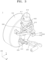
- FIG. 3 is a perspective view schematically illustrating a configuration of the corner module apparatus according to the first embodiment of the present disclosure.
- FIG. 4 is a side view schematically illustrating the configuration of the corner module apparatus according to the first embodiment of the present disclosure.
- FIG. 5 is a front view schematically illustrating the configuration of the corner module apparatus according to the first embodiment of the present disclosure.
- FIG. 6 is an exploded perspective view schematically illustrating the configuration of the corner module apparatus according to the first embodiment of the present disclosure.
- the suspension arm 200 extends from the drive unit 100 and supports the drive unit 100 with respect to the vehicle body B. More specifically, the suspension arm 200 may function as a component, which connects the wheel W to the vehicle body and at the same time absorbs a load applied from the wheel W while the vehicle is traveling by its own rigidity, and controls the movement of the wheel W.
- the suspension arm 200 may extends in the longitudinal direction thereof, which is in the width direction of the vehicle, namely, in the Y-axis direction in FIG. 1 , and may have both ends disposed to face the vehicle body B and the drive unit 100, respectively.
- the suspension arm 200 may be rotatably connected, at one end thereof, to the vehicle body B, more specifically, to the lower bracket L, via a bush or the like.
- the suspension arm 200 may be rotatably connected, at one end thereof, to the lower bracket L in the longitudinal direction of the vehicle, namely, in a direction parallel to the X-axis FIG. 1 . Accordingly, the suspension arm 200 may rotate relative to the vehicle body B during bump and rebound movements of the wheel W and perform a suspension behavior.
- the suspension arm 200 may be rotatably connected, at the other end thereof, to one surface of the drive unit 100 facing the vehicle body B.
- the suspension arm 200 may be rotatably connected, at the other end thereof, to one surface of the drive unit 100 in a multi-axis manner by a ball joint or the like. Accordingly, the suspension arm 200 may guide the bump and rebound movements of the wheel W while inducing a natural steering movement of the wheel W.
- the shock absorber 300 is connected, at one side thereof, to the drive unit 100 and is stretchable longitudinally. The other side of the shock absorber 300 may be connected to the steering drive member 400.
- the shock absorber 300 may function as a component that absorbs shock or vibration transmitted from the wheel W when the vehicle travels or when the wheel W bumps or rebounds.
- the shock absorber 300 may have both longitudinal sides spaced vertically. In this case, the shock absorber 300 may be disposed such that its central axis 301 is inclined at a predetermined angle with respect to the direction perpendicular to the ground, namely, the Z-axis direction in FIG. 1 .
- the shock absorber 300 may include a cylinder 310, a piston rod 320, and a spring 330.
- the cylinder 310 defines an external appearance of one side of the shock absorber 300 and is fixed to the drive unit 100.
- the cylinder 310 according to this embodiment may have a hollow cylindrical shape with an open upper end.
- the cylinder 310 may be filled therein with a fluid such as oil capable of performing a damping function.
- the cylinder 310 may have an outer surface fixed to one surface of the drive unit 100 facing the vehicle body B.
- the cylinder 310 may be integrally fixed to one surface of the drive unit 100 by welding or the like, or may be detachably fixed to one surface of the drive unit 100 by bolting or the like.
- the piston rod 320 defines an external appearance of the other side of the shock absorber 300 and is slidably installed in the cylinder 310.
- the piston rod 320 according to this embodiment may be in the form of a substantially rod, and may have a lower end inserted into the cylinder 310 through the upper end of the cylinder 310.
- the upper end of the piston rod 320 may be connected to the steering drive member 400.
- the piston rod 320 may reciprocate in the longitudinal direction of the cylinder 310, namely, in a direction parallel to the central axis 301 of the shock absorber 300 when the wheel W moves up and down.
- the steering drive member 400 is fixed to the vehicle body B, and generates a steering force for a steering movement of the wheel W.
- the steering drive member 400 may be connected to the other side of the shock absorber 300 and may support the other side of the shock absorber 300 with respect to the vehicle body B at a fixed position.
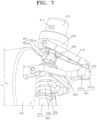
- FIG. 7 is an enlarged view schematically illustrating a configuration of the steering drive member and the steering transmission member according to the first embodiment of present disclosure.
- the steering drive member 400 may include a steering actuator 410, a rotating body 420, and a steering joint 430.
- the steering actuator 410 may be fixed to the vehicle body B, more specifically, to the upper bracket U.
- the steering actuator 410 may have a hook 411 protruding in the radial direction of the steering actuator 410 from the outer surface of the steering actuator 410.
- the hook 411 may consist of a plurality of hooks spaced apart from each other along the circumferential surface of the steering actuator 410.
- the steering actuator 410 may be inserted so as to pass through the upper bracket U vertically.
- the steering actuator 410 may be fixed to the vehicle body B as the hook 411 is latched to the upper surface of the upper bracket U.
- the present disclosure is not limited thereto.
- the steering actuator 410 may be fixed to the upper bracket U by welding, bolting, or the like.
- the rotating body 420 is connected to the steering actuator 410 and rotates about a steering axis 401 by receiving the rotational force from the steering actuator 410.
- the steering axis 401 may function as a central axis of the rotational force transmitted from the steering actuator 410 to the steering transmission member 500.
- the steering axis 401 may be inclined at a predetermined angle with respect to a direction perpendicular to the ground, namely, a direction parallel to the Z-axis. As illustrated in FIG. 3 , the steering axis 401 may be disposed to intersect the central axis 301 of the shock absorber 300 at any one point, or alternatively the steering axis 401 may be disposed on the same straight line as the central axis 301 of the shock absorber 300.
- the rotating body 420 may have a substantially cylindrical shape, and may be disposed such that its upper end faces the lower end of the steering actuator 410. In this case, the rotating body 420 may be disposed such that its central axis is positioned coaxially with the steering axis 401.
- the rotating body 420 may be rotatably supported, at the upper end thereof, on the lower end of the steering actuator 410.
- the rotating body 420 may be connected to the reducer of the steering actuator 410 and may receive the rotational force generated by the steering motor through the reducer. Accordingly, the rotating body 420 may be rotated clockwise or counterclockwise about the steering axis 401 when the steering actuator 410 is operated.
- the steering joint 430 is provided between the rotating body 420 and the shock absorber 300 and rotatably supports the rotating body 420 with respect to the shock absorber 300. That is, the steering joint 430 may function as a component, which interconnects the shock absorber 300 and the steering drive member 400 and at the same time absorbs the torsional force generated between the shock absorber 300 and the steering drive member 400 during the suspension behavior and steering movement of the wheel W.
- the steering joint 430 may include a steering socket 431 and a steering ball joint 432.
- the steering socket 431 is connected to the rotating body 420 and the steering ball joint 432 is connected to the shock absorber 300.
- the present disclosure is not limited thereto.
- the steering socket 431 may be connected to the shock absorber 300 and the steering ball joint 432 may be connected to the rotating body 420.
- the steering socket 431 may extend downward from the lower end of the rotating body 420.
- the steering socket 431 may be elastically deformable.
- the steering socket 431 may include a plurality of steering socket blades 431a spaced apart from each other along one circumference centered on the steering axis 401.
- the plurality of steering socket blades 431a may each be made of an elastically deformable material such as plastic. Accordingly, the plurality of steering socket blades 431a may be gathered or spread out around the steering axis 401 while the steering ball joint 432 is inserted into or removed from the steering socket 431.
- the steering ball joint 432 may be connected to the shock absorber 300, more specifically, to the upper end of the piston rod 320.
- the steering ball joint 432 may be in the form of a substantially sphere and may be inserted into the steering socket 431.
- the steering ball joint 432 may be rotatably supported around a number of axes inside the steering socket 431. Accordingly, the steering ball joint 432 allows the angle of the central axis 301 of the shock absorber 300 with respect to the steering axis 401 to change in all directions, thereby inducing a more smooth suspension behavior and steering movement of the wheel W.
- the static friction force between the steering socket 431 and the steering ball joint 432 may be set smaller than the magnitude of the rotational force transmitted from the steering actuator 410 to the rotating body 420. Accordingly, the steering socket 431 and the steering ball joint 432 may rotate relative to each other during the steering movement of the wheel W, thereby inducing the steering force generated by the steering actuator 410 to be smoothly transmitted to the steering transmission member 500.
- the steering transmission member 500 is provided between the steering drive member 400 and the drive unit 100, and varies the steering angle of the wheel W in conjunction with the steering force generated by the steering drive member 400. That is, the steering transmission member 500 may function as a component that transmits the rotational force generated by the steering drive member 400 to the wheel W.
- the steering transmission member 500 may include a first transmission link 510, a second transmission link 520, and a transmission joint 530.
- the first transmission link 510 defines an external appearance of one side of the steering transmission member 500, and is rotatably connected to the rotating body 420.
- the first transmission link 510 may be in the form of various types of link arms.
- the first transmission link 510 may be rotatably connected, at one end thereof, to the outer surface of the rotating body 420 via a bush, a bearing, or the like.
- the first transmission link 510 may be rotated about the steering axis 401 along with the rotation of the rotating body 420.
- the first transmission link 510 may be rotatably connected, at one end thereof, to the rotating body 420 around a first hinge axis 501 that intersects the steering axis 401. Accordingly, the first transmission link 510 may be rotated about the first hinge axis 501 with respect to the rotating body 420 during the bump and rebound movements of the wheel W, and may perform a suspension behavior together with the suspension arm 200.
- the second transmission link 520 defines an external appearance of the other side of the steering transmission member 500, and is rotatably connected to the drive unit 100.
- the second transmission link 520 may be in the form of various types of link arms.
- the second transmission link 520 may be rotatably connected, at one end thereof, to one surface of the drive unit 100 facing the vehicle body B via a bush, a bearing, or the like.
- the second transmission link 520 may receive the rotational force of the first transmission link 510 through the transmission joint 530 when the wheel W is steered, may rotate together with the first transmission link 510, and may vary the steering angle of the wheel W.
- the second transmission link 520 may intersect the steering axis 401.
- the second transmission link 520 may be rotatably connected, at one end thereof, to the drive unit 100 around a second hinge axis 502 vertically spaced apart from the first hinge axis 501.
- the second hinge axis 502 may be parallel to the first hinge axis 501, or alternatively may be inclined with respect to the first hinge axis 501. Accordingly, the second transmission link 520 may be rotated about the second hinge axis 502 with respect to the rotating body 420 during the bump and rebound movements of the wheel W, and may perform a suspension behavior together with the suspension arm 200.
- the transmission joint 530 is provided between the first transmission link 510 and the second transmission link 520, and supports the first and second transmission links 510 and 520 to be relatively rotatable. That is, the transmission joint 530 may function as a component, which transmits to the second transmission link 520 the rotational force input from the rotating body 420 to the first transmission link 510 and at the same time absorbs the torsional force generated between the first transmission link 510 and the second transmission link 520 during the suspension behavior and steering movement of the wheel W.
- the transmission joint 530 may include a transmission socket 531 and a transmission ball joint 532.
- the transmission socket 531 is connected to the second transmission link 520 and the transmission ball joint 532 is connected to the first transmission link 510.
- the present disclosure is not limited thereto.
- the transmission socket 531 may be connected to the first transmission link 510 and the transmission ball joint 532 may be connected to the second transmission link 520.
- the transmission socket 531 may extend from the other end of the second transmission link 520.
- the transmission socket 531 may be elastically deformable.
- the transmission socket 531 may include a plurality of transmission socket blades 531a spaced apart from each other along one circumference centered on the other end of the second transmission link 520.
- the plurality of transmission socket blades 531a may each be made of an elastically deformable material such as plastic. Accordingly, the plurality of transmission socket blades 531a may be gathered or spread out while the transmission ball joint 532 is inserted into or removed from the transmission socket 531.
- the transmission ball joint 532 may extend from the other end of the first transmission link 510.
- the transmission ball joint 532 may be in the form of a substantially sphere and may be inserted into the transmission socket 531.
- the transmission ball joint 532 may be rotatably supported around a number of axes inside the transmission socket 531. Accordingly, the transmission ball joint 532 allows the angle of the second transmission link 520 with respect to the first transmission link 510 to change in all directions, thereby inducing a more smooth suspension behavior and steering movement of the wheel W.
- the kinetic friction force between the transmission socket 531 and the transmission ball joint 532 may be set greater than the magnitude of the rotational force transmitted from the rotating body 420 to the first transmission link 510. Accordingly, the transmission socket 531 and the transmission ball joint 532 limit the relative rotation between the first transmission link 510 and the second transmission link 520 during normal steering operation so as to smoothly transmit the steering force to the wheel W. On the other hand, the transmission socket 531 and the transmission ball joint 532 allow the relative rotation between the first transmission link 510 and the second transmission link 520 at a certain angle only when an excessive torsional load is applied between the first transmission link 510 and the second transmission link 520, thereby preventing damage to parts.
- FIG. 8 is a view schematically illustrating a suspension operation of the corner module apparatus according to the first embodiment of the present disclosure.
- the suspension arm 200 adjusts the installation angles of the drive unit 100 and the vehicle body B at both ends thereof and guides the movement of the wheel W.
- the shock absorber 300 is compressed or extended longitudinally and applies a buffering force in a direction opposite to the movement direction of the wheel W.
- the first transmission link 510 and the second transmission link 520 connected, at the respective ends thereof, to the rotating body 420 and the drive unit 100 have variable relative angle by the relative rotation between the transmission socket 531 and the transmission ball joint 532, and guide the movement of the wheel W together with the suspension arm 200.
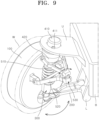
- FIG. 9 is a view schematically illustrating a steering operation of the corner module apparatus according to the first embodiment of the present disclosure.
- the steering actuator 410 when the vehicle turns, the steering actuator 410 generates a rotational force, and the rotating body 420 is rotated clockwise or counterclockwise about the steering axis 401 by the rotational force generated from the steering actuator 410.
- the first transmission link 510 As one end of the first transmission link 510 is connected to the rotating body 420, the first transmission link 510 is rotated about the steering axis 401 together with the rotating body 420.
- the transmission socket 531 and the transmission ball joint 532 do not rotate relative to each other, and the second transmission link 520 rotates together with the first transmission link 510.
- the drive unit 100 connected, at one surface thereof, to one end of the second transmission link 520 rotates together with the second transmission link 520 and varies the steering angle of the wheel W.
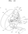
- FIG. 10 is a perspective view schematically illustrating a configuration of the corner module apparatus according to the second embodiment of the present disclosure.
- FIG. 11 is a front view schematically illustrating the configuration of the corner module apparatus according to the second embodiment of the present disclosure.
- the corner module apparatus 2 may include a drive unit 100, a suspension arm 200, a shock absorber 300, a steering drive member 400, and a steering transmission member 500.
- the corner module apparatus 2 according to this embodiment may have the same configuration as the corner module apparatus 1 according to the first embodiment of the present disclosure, with the sole exception of a detailed configuration of the shock absorber 300. Therefore, in the corner module apparatus 2 according to this embodiment, only the detailed configuration of the shock absorber 300 different from that of the corner module apparatus 1 according to the first embodiment of the present disclosure will be described. The description of the corner module apparatus 1 according to the first embodiment of the present disclosure may be applied as it is to the remaining configurations of the corner module apparatus 2 according to this embodiment.
- the shock absorber 300 may consist of a pair of shock absorbers.
- the pair of shock absorbers 300 may be disposed parallel to each other.
- the central axes 301 of the pair of shock absorbers 300 may be spaced apart from each other with the steering axis 401 interposed therebetween. That is, unlike the first embodiment, the central axes 301 of the pair of shock absorbers 300 may be disposed so as not to intersect the steering axis 401 at any one point.
- the corner module apparatus 2 can distribute to the pair of shock absorbers 300 the shock generated during the bump and rebound movements of the wheel W, and can reduce the height of the shock absorbers 300 in relation to the same load, thereby making it easy to implement a low-floor vehicle.
- the corner module apparatus 2 according to this embodiment may easily utilize the shock absorbers 300 having various lengths as the central axes 301 of the shock absorbers 300 are spaced apart from the steering axis 401.
- connection bracket 302. The upper ends of the piston rods 320 provided in the pair of shock absorbers 300 may be interconnected by a connection bracket 302.
- the steering ball joint 432 may be connected to the upper surface of the connection bracket 302.
- FIG. 12 is a perspective view schematically illustrating an installation state of the corner module apparatus according to the third embodiment of the present disclosure.
- FIG. 13 is a view schematically illustrating an assembly process of the corner module apparatus according to the third embodiment of the present disclosure.
- FIG. 14 is a perspective view schematically illustrating a configuration of the corner module apparatus according to the third embodiment of the present disclosure.
- FIG. 15 is a side view schematically illustrating the configuration of the corner module apparatus according to the third embodiment of the present disclosure.
- the corner module apparatus 3 may include a drive unit 100, a suspension arm 200, a shock absorber 300, a steering drive member 400, a steering transmission member 500, and a module body 600.
- the corner module apparatus 3 according to this embodiment may have the same configuration as the corner module apparatus 1 according to the first embodiment of the present disclosure, with the sole exception of the module body 600. Therefore, in the corner module apparatus 3 according to this embodiment, only the module body 600 different from the components of the corner module apparatus 1 according to the first embodiment of the present disclosure will be described. The description of the corner module apparatus 1 according to the first embodiment of the present disclosure may be applied as it is to the remaining configurations of the corner module apparatus 3 according to this embodiment.
- the vehicle body B according to this embodiment may have no upper bracket U and no lower bracket L. Accordingly, the other end of the suspension arm 200 and the steering actuator 410 according to this embodiment may be separated from the vehicle body B.
- the module body 600 is detachably coupled to the vehicle body B, and supports the suspension arm 200 and the steering drive member 400 with respect to the vehicle body B. That is, the module body 600 may function as a component that integrates the drive unit 100, the suspension arm 200, the shock absorber 300, the steering drive member 400, and the steering transmission member 500 into a single unit module. Accordingly, the module body 600 can further simplify the shape of the vehicle body B and can simplify the assembly process of the corner module apparatus 3 to the vehicle body B.
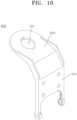
- FIG. 16 is a perspective view schematically illustrating the configuration of the module body according to the third embodiment of present disclosure.
- the module body 600 may include a first body 610 and a second body 620.
- the first body 610 defines an external appearance of the lower side of the module body 600 and is connected to the suspension arm 200. That is, the first body 610 may function as a component that supports the suspension arm 200 with respect to the vehicle body B.
- the first body 610 according to this embodiment may be in the form of a plate extending in the height direction of the vehicle, namely, in the Z-axis direction in FIG. 12 .
- the first body 610 may be disposed such that its inner surface faces the drive unit 100 at a predetermined distance therefrom in the width direction of the vehicle, namely, in the Y-axis direction in FIG. 12 .
- the outer surface of the first body 610 may be detachably coupled to the side surface of the vehicle body B.
- the first body 610 may be detachably coupled to the side surface of the vehicle body B by various types of coupling methods such as bolting, fitting, and hooking.
- As the first body 610 is coupled to the side surface of the vehicle body B it is possible to more easily implement a low-floor vehicle compared to the case where the first body 610 is coupled to the upper or lower end of the vehicle body B.
- the lower end of the first body 610 may be connected to the other end of the suspension arm 200.
- the first body 610 may rotatably support the other end of the suspension arm 200 via a bush or the like.
- the second body 620 defines an external appearance of the upper side of the module body 600 and is connected to the steering drive member 400. That is, the second body 620 may function as a component that supports the steering drive member 400 with respect to the vehicle body B.
- the second body 620 according to this embodiment may be in the form of a plate extending in the width direction of the vehicle body from the upper end of the first body 610.
- the second body 620 may have an insertion hole 621 formed therethrough vertically. The upper end of the steering actuator 410 may be inserted into the insertion hole 621, and the hook 411 may be latched to the upper surface of the second body 620.
- FIG. 17 is a perspective view schematically illustrating a configuration of the corner module apparatus according to the fourth embodiment of the present disclosure.
- FIG. 18 is a front view schematically illustrating the configuration of the corner module apparatus according to the fourth embodiment of the present disclosure.
- the corner module apparatus 4 may include a drive unit 100, a suspension arm 200, a shock absorber 300, a steering drive member 400, a steering transmission member 500, and a module body 600.
- the corner module apparatus 4 according to this embodiment may have the same configuration as the corner module apparatus 3 according to the third embodiment of the present disclosure, with the sole exception of a detailed configuration of the shock absorber 300. Therefore, in the corner module apparatus 4 according to this embodiment, only the detailed configuration of the shock absorber 300 different from that of the corner module apparatus 3 according to the third embodiment of the present disclosure will be described. The description of the corner module apparatus 3 according to the third embodiment of the present disclosure may be applied as it is to the remaining configurations of the corner module apparatus 4 according to this embodiment.
- the shock absorber 300 may consist of a pair of shock absorbers.
- the pair of shock absorbers 300 may be disposed parallel to each other.
- the central axes 301 of the pair of shock absorbers 300 may be spaced apart from each other with the steering axis 401 interposed therebetween. That is, unlike the third embodiment, the central axes 301 of the pair of shock absorbers 300 may be disposed so as not to intersect the steering axis 401 at any one point.
- the corner module apparatus 4 according to this embodiment can distribute to the pair of shock absorbers 300 the shock generated during the bump and rebound movements of the wheel W, and can reduce the height of the shock absorbers 300 in relation to the same load, thereby making it easy to implement a low-floor vehicle.
- the corner module apparatus 4 according to this embodiment may easily utilize the shock absorbers 300 having various lengths as the central axes 301 of the shock absorbers 300 are spaced apart from the steering axis 401.
- connection bracket 302. The upper ends of the piston rods 320 provided in the pair of shock absorbers 300 may be interconnected by a connection bracket 302.
- the steering ball joint 432 may be connected to the upper surface of the connection bracket 302.
Landscapes
- Engineering & Computer Science (AREA)
- Mechanical Engineering (AREA)
- Chemical & Material Sciences (AREA)
- Combustion & Propulsion (AREA)
- Transportation (AREA)
- Vehicle Body Suspensions (AREA)
Abstract
Description
- Exemplary embodiments of the present disclosure relate to a corner module apparatus, and more particularly, to a corner module apparatus with driving, braking, steering, and suspension systems configured integrally.
- In general, an electric vehicle refers to an eco-friendly vehicle that does not emit exhaust gas at all. The electric vehicle is equipped with a high-voltage battery that supplies energy for traveling, a travel motor that generates a rotational force from the power output from the high-voltage battery, and the like, and transmits the rotational force of the motor to wheels through drive shafts to travel.
- Recently, an in-wheel motor vehicle is in the spotlight, in which a motor is installed directly inside a wheel to directly transmit power from the motor to the wheel, in consideration of the advantages of reducing the weight of the vehicle by removing intermediate power transmission devices such as reducers and differential gears and of reducing energy loss in the process of power transmission. Furthermore, development of wheels in which braking, steering, and suspension systems as well as a driving system are configured integrally is actively being carried out.
- The related art of the present disclosure is disclosed in
Korean Patent Application Publication No. 10-2019-0041855 (published on April 23, 2019 - This Summary is provided to introduce a selection of concepts in a simplified form that are further described below in the Detailed Description. This Summary is not intended to identify key features or essential features of the claimed subject matter, nor is it intended to be used as an aid in determining the scope of the claimed subject matter.
- Various embodiments are directed to a corner module apparatus which is capable of independently controlling movements of individual wheels.
- In an embodiment, a corner module apparatus includes a drive unit configured to provide a driving force to a wheel, a suspension arm configured to support the drive unit with respect to a vehicle body, a shock absorber connected at one side thereof to the drive unit and provided to be stretchable, a steering drive member configured to support the other side of the shock absorber with respect to the vehicle body and to generate a steering force, and a steering transmission member provided between the steering drive member and the drive unit and configured to vary a steering angle of the wheel in conjunction with the steering force generated by the steering drive member.
- The steering drive member may include a steering actuator fixed to the vehicle body and configured to generate a rotational force, a rotating body connected to the steering actuator and rotated about a steering axis by receiving the rotational force from the steering actuator, and a steering joint provided between the rotating body and the shock absorber and configured to rotatably support the rotating body with respect to the shock absorber.
- The corner module apparatus may further include a plurality of hooks protruding from the steering actuator, spaced along a circumferential surface of the steering actuator, and latched to the vehicle body.
- The steering joint may include a steering socket connected to one of the shock absorber and the rotating body, and a steering ball joint connected to the other of the shock absorber and the rotating body and inserted into the steering socket.
- The steering transmission member may include a first transmission link rotatably connected to the rotating body, a second transmission link rotatably connected to the drive unit, and a transmission joint provided between the first transmission link and the second transmission link and configured to support the first transmission link and the second transmission link to be relatively rotatable.
- The first transmission link may be rotatably connected to the rotating body around a first hinge axis intersecting the steering axis, and the second transmission link may be rotatably connected to the drive unit around a second hinge axis that intersects the steering shaft and is spaced apart from the first hinge axis.
- The transmission joint may include a transmission socket connected to one of the first transmission link and the second transmission link, and a transmission ball joint connected to the other of the first transmission link and the second transmission link and inserted into the transmission socket.
- The shock absorber may consist of a pair of shock absorbers, and the pair of shock absorbers may have central axes spaced apart from each other with the steering axis interposed therebetween.
- In another embodiment, there is provided a corner module apparatus that includes a drive unit configured to provide a driving force to a wheel, a suspension arm extending from the drive unit, a shock absorber connected at one side thereof to the drive unit and provided to be stretchable, a steering drive member connected to the other side of the shock absorber and configured to generate a steering force, a steering transmission member provided between the steering drive member and the drive unit and configured to vary a steering angle of the wheel in conjunction with the steering force generated by the steering drive member, and a module body detachably coupled to a vehicle body and configured to support the suspension arm and the steering drive member with respect to the vehicle body.
- The module body may include a first body detachably coupled to a side surface of the vehicle body and connected to the suspension arm, and a second body extending from the first body and connected to the steering drive member.
- The steering drive member may include a steering actuator fixed to the second body and configured to generate a rotational force, a rotating body connected to the steering actuator and rotated about a steering axis by receiving the rotational force from the steering actuator, and a steering joint provided between the rotating body and the shock absorber and configured to rotatably support the rotating body with respect to the shock absorber.
- The steering transmission member may include a first transmission link rotatably connected to the rotating body, a second transmission link rotatably connected to the drive unit, and a transmission joint provided between the first transmission link and the second transmission link and configured to support the first transmission link and the second transmission link to be relatively rotatable.
- The first transmission link may be rotatably connected to the rotating body around a first hinge axis intersecting the steering axis, and the second transmission link may be rotatably connected to the drive unit around a second hinge axis that intersects the steering shaft and is spaced apart from the first hinge axis.
- The transmission joint may include a transmission socket connected to one of the first transmission link and the second transmission link, and a transmission ball joint connected to the other of the first transmission link and the second transmission link and inserted into the transmission socket.
- The shock absorber may consist of a pair of shock absorbers, and the pair of shock absorbers may have central axes spaced apart from each other with the steering axis interposed therebetween.
- As apparent from the above description, the corner module apparatus according to the present disclosure can ensure a robust structure as the upper and lower ends of the apparatus are supported by the vehicle body, thereby implementing stable suspension and steering operations.
- In addition, the corner module apparatus according to the present disclosure can prevent damage to parts due to torsional load generated during the suspension behavior and the steering operation by the steering joint and the transmission joint.
- In addition, the corner module apparatus according to the present disclosure can distribute to the pair of shock absorbers the shock generated during the bump and rebound movements of the wheel, and can reduce the height of the shock absorbers in relation to the same load, thereby making it easy to implement a low-floor vehicle.
- Moreover, since the central axes of the pair of shock absorbers are spaced apart from the steering axis in the corner module apparatus according to the present invention, it is possible to easily lengthen the shock absorbers having various lengths.
- In addition, in the corner module apparatus according to the present invention, the module body can integrate individual components into a single unit module, and it is possible to increase the overall rigidity of the product and make assembly simple.
- Furthermore, the corner module apparatus according to the present invention can easily implement a low-floor vehicle as the module body is coupled to the side surface of the vehicle body.
-
-
FIG. 1 is a perspective view schematically illustrating an installation state of a corner module apparatus according to a first embodiment of the present disclosure. -
FIG. 2 is an enlarged view schematically illustrating the installation state of the corner module apparatus according to the first embodiment of the present disclosure. -
FIG. 3 is a perspective view schematically illustrating a configuration of the corner module apparatus according to the first embodiment of the present disclosure. -
FIG. 4 is a side view schematically illustrating the configuration of the corner module apparatus according to the first embodiment of the present disclosure. -
FIG. 5 is a front view schematically illustrating the configuration of the corner module apparatus according to the first embodiment of the present disclosure. -
FIG. 6 is an exploded perspective view schematically illustrating the configuration of the corner module apparatus according to the first embodiment of the present disclosure. -
FIG. 7 is an enlarged view schematically illustrating a configuration of a steering drive member and a steering transmission member according to the first embodiment of present disclosure. -
FIG. 8 is a view schematically illustrating a suspension operation of the corner module apparatus according to the first embodiment of the present disclosure. -
FIG. 9 is a view schematically illustrating a steering operation of the corner module apparatus according to the first embodiment of the present disclosure. -
FIG. 10 is a perspective view schematically illustrating a configuration of a corner module apparatus according to a second embodiment of the present disclosure. -
FIG. 11 is a front view schematically illustrating the configuration of the corner module apparatus according to the second embodiment of the present disclosure. -
FIG. 12 is a perspective view schematically illustrating an installation state of a corner module apparatus according to a third embodiment of the present disclosure. -
FIG. 13 is a view schematically illustrating an assembly process of the corner module apparatus according to the third embodiment of the present disclosure. -
FIG. 14 is a perspective view schematically illustrating a configuration of the corner module apparatus according to the third embodiment of the present disclosure. -
FIG. 15 is a side view schematically illustrating the configuration of the corner module apparatus according to the third embodiment of the present disclosure. -
FIG. 16 is a perspective view schematically illustrating a configuration of a module body according to the third embodiment of present disclosure. -
FIG. 17 is a perspective view schematically illustrating a configuration of a corner module apparatus according to a fourth embodiment of the present disclosure. -
FIG. 18 is a front view schematically illustrating the configuration of the corner module apparatus according to the fourth embodiment of the present disclosure. - The following detailed description is provided to assist the reader in gaining a comprehensive understanding of the methods, apparatuses, and/or systems described herein. However, various changes, modifications, and equivalents of the methods, apparatuses, and/or systems described herein will be apparent after an understanding of the disclosure of this application. For example, the sequences of operations described herein are merely examples, and are not limited to those set forth herein, but may be changed as will be apparent after an understanding of the disclosure of this application, with the exception of operations necessarily occurring in a certain order.
- The features described herein may be embodied in different forms and are not to be construed as being limited to the examples described herein. Rather, the examples described herein have been provided merely to illustrate some of the many possible ways of implementing the methods, apparatuses, and/or systems described herein that will be apparent after an understanding of the disclosure of this application.
- Advantages and features of the present disclosure and methods of achieving the advantages and features will be clear with reference to embodiments described in detail below together with the accompanying drawings. However, the present disclosure is not limited to the embodiments disclosed herein but will be implemented in various forms. The embodiments of the present disclosure are provided so that the present disclosure is completely disclosed, and a person with ordinary skill in the art can fully understand the scope of the present disclosure. The present disclosure will be defined only by the scope of the appended claims. Meanwhile, the terms used in the present specification are for explaining the embodiments, not for limiting the present disclosure.
- Terms, such as first, second, A, B, (a), (b) or the like, may be used herein to describe components. Each of these terminologies is not used to define an essence, order or sequence of a corresponding component but used merely to distinguish the corresponding component from other component(s). For example, a first component may be referred to as a second component, and similarly the second component may also be referred to as the first component.
- Throughout the specification, when a component is described as being "connected to," or "coupled to" another component, it may be directly "connected to," or "coupled to" the other component, or there may be one or more other components intervening therebetween. In contrast, when an element is described as being "directly connected to," or "directly coupled to" another element, there can be no other elements intervening therebetween.
- The singular forms "a", "an", and "the" are intended to include the plural forms as well, unless the context clearly indicates otherwise. It will be further understood that the terms "comprises/comprising" and/or "includes/including" when used herein, specify the presence of stated features, integers, steps, operations, elements, and/or components, but do not preclude the presence or addition of one or more other features, integers, steps, operations, elements, components and/or groups thereof.
- Hereinafter, a corner module apparatus according to exemplary embodiments of the present disclosure will be described with reference to the accompanying drawings.
-
FIG. 1 is a perspective view schematically illustrating an installation state of a corner module apparatus according to a first embodiment of the present disclosure.FIG. 2 is an enlarged view schematically illustrating the installation state of the corner module apparatus according to the first embodiment of the present disclosure. - Referring to
FIGS. 1 and2 , the corner module apparatus, which is designated byreference numeral 1, according to the first embodiment is installed between a vehicle body B and a wheel W and generally performs operations such as driving, braking, steering, and suspension. Thecorner module apparatus 1 may consist of a plurality of corner module apparatuses. The plurality ofcorner module apparatuses 1 may be connected to individual wheels W, respectively. The plurality ofcorner module apparatuses 1 may independently perform operations such as driving, braking, steering, and suspension of the wheels W.FIGS. 1 and2 illustrate fourcorner module apparatuses 1 as an example, but the present disclosure is not limited thereto. For example, the number of corner module apparatuses may vary depending on the number of wheels or the like by design. - The vehicle body B may be exemplified by various types of structures that form the framework of a vehicle, such as a chassis frame and a subframe.
FIGS. 1 and2 illustrate that the vehicle body B is in the form of a rectangular frame as an example, but the present disclosure is not limited thereto. For example, the vehicle body B may be changed in various forms by design. - The vehicle body B may have an upper bracket U and a lower bracket L formed on the respective top and bottom thereof to support an associated one of the
corner module apparatuses 1. The number of upper brackets and lower brackets may correspond to the number of corner module apparatuses. -
FIG. 3 is a perspective view schematically illustrating a configuration of the corner module apparatus according to the first embodiment of the present disclosure.FIG. 4 is a side view schematically illustrating the configuration of the corner module apparatus according to the first embodiment of the present disclosure.FIG. 5 is a front view schematically illustrating the configuration of the corner module apparatus according to the first embodiment of the present disclosure.FIG. 6 is an exploded perspective view schematically illustrating the configuration of the corner module apparatus according to the first embodiment of the present disclosure. - Referring to
FIGS. 3 to 6 , thecorner module apparatus 1 according to this embodiment includes adrive unit 100, asuspension arm 200, ashock absorber 300, asteering drive member 400, and asteering transmission member 500. - The
drive unit 100 is connected to the wheel W and provides a driving force to the wheel W. Thedrive unit 100 according to this embodiment may be exemplified by various types of in-wheel motors, which each are installed inside the wheel W and generate a rotational force for rotating the wheel W by receiving power from the outside. Thedrive unit 100 may have a diameter smaller than the diameter of the wheel W, and may be disposed inside the wheel W. Thedrive unit 100 may be disposed such that its central axis is coaxial with the central axis of the wheel W. Thedrive unit 100 may be connected to the wheel W via a wheel bearing (not shown) or the like. - The
drive unit 100 may be equipped therein with an additional braking unit (not shown), which includes a brake disc configured to rotate together with the wheel W and a brake caliper configured to selectively interfere with the rotation of the brake disc and apply or release a braking force to or from the wheel W. - The
suspension arm 200 extends from thedrive unit 100 and supports thedrive unit 100 with respect to the vehicle body B. More specifically, thesuspension arm 200 may function as a component, which connects the wheel W to the vehicle body and at the same time absorbs a load applied from the wheel W while the vehicle is traveling by its own rigidity, and controls the movement of the wheel W. - The
suspension arm 200 according to this embodiment may extends in the longitudinal direction thereof, which is in the width direction of the vehicle, namely, in the Y-axis direction inFIG. 1 , and may have both ends disposed to face the vehicle body B and thedrive unit 100, respectively. - The
suspension arm 200 may be rotatably connected, at one end thereof, to the vehicle body B, more specifically, to the lower bracket L, via a bush or the like. In this case, thesuspension arm 200 may be rotatably connected, at one end thereof, to the lower bracket L in the longitudinal direction of the vehicle, namely, in a direction parallel to the X-axisFIG. 1 . Accordingly, thesuspension arm 200 may rotate relative to the vehicle body B during bump and rebound movements of the wheel W and perform a suspension behavior. - The
suspension arm 200 may be rotatably connected, at the other end thereof, to one surface of thedrive unit 100 facing the vehicle body B. In this case, thesuspension arm 200 may be rotatably connected, at the other end thereof, to one surface of thedrive unit 100 in a multi-axis manner by a ball joint or the like. Accordingly, thesuspension arm 200 may guide the bump and rebound movements of the wheel W while inducing a natural steering movement of the wheel W. -
FIGS. 3 to 6 illustrate that asingle suspension arm 200 is formed as an example, but the present disclosure is not limited thereto. For example, a plurality of suspension arms may be formed. In this case, the plurality ofsuspension arms 200 may be spaced apart from each other in the height direction of the vehicle body B, namely, in a direction parallel to the Z-axis inFIG. 1 . - The
shock absorber 300 is connected, at one side thereof, to thedrive unit 100 and is stretchable longitudinally. The other side of theshock absorber 300 may be connected to thesteering drive member 400. Theshock absorber 300 may function as a component that absorbs shock or vibration transmitted from the wheel W when the vehicle travels or when the wheel W bumps or rebounds. Theshock absorber 300 may have both longitudinal sides spaced vertically. In this case, theshock absorber 300 may be disposed such that itscentral axis 301 is inclined at a predetermined angle with respect to the direction perpendicular to the ground, namely, the Z-axis direction inFIG. 1 . - The
shock absorber 300 according to this embodiment may include acylinder 310, apiston rod 320, and aspring 330. - The
cylinder 310 defines an external appearance of one side of theshock absorber 300 and is fixed to thedrive unit 100. Thecylinder 310 according to this embodiment may have a hollow cylindrical shape with an open upper end. Thecylinder 310 may be filled therein with a fluid such as oil capable of performing a damping function. Thecylinder 310 may have an outer surface fixed to one surface of thedrive unit 100 facing the vehicle body B. In this case, thecylinder 310 may be integrally fixed to one surface of thedrive unit 100 by welding or the like, or may be detachably fixed to one surface of thedrive unit 100 by bolting or the like. - The
piston rod 320 defines an external appearance of the other side of theshock absorber 300 and is slidably installed in thecylinder 310. Thepiston rod 320 according to this embodiment may be in the form of a substantially rod, and may have a lower end inserted into thecylinder 310 through the upper end of thecylinder 310. The upper end of thepiston rod 320 may be connected to thesteering drive member 400. As thesteering drive member 400 is fixed at a certain position, thepiston rod 320 may reciprocate in the longitudinal direction of thecylinder 310, namely, in a direction parallel to thecentral axis 301 of theshock absorber 300 when the wheel W moves up and down. - Both sides of the
spring 330 are connected to thecylinder 310 and thepiston rod 320, respectively, and thespring 330 is elastically deformed in conjunction with the sliding of thepiston rod 320. That is, thespring 330 may function as a component that absorbs shock by applying an elastic restoring force in a direction opposite to the sliding of thepiston rod 320. Thespring 330 according to this embodiment may be in the form of a coil spring. Thespring 330 may be disposed such that its inner surface surrounds the outer surfaces of thecylinder 310 and thepiston rod 320. Thespring 330 may have lower and upper ends fixed to thecylinder 310 and thepiston rod 320, respectively. In this case, the lower and upper ends of thespring 330 may be directly fixed to thecylinder 310 and thepiston rod 320, respectively, or alternatively may be fixed to thecylinder 310 and thepiston rod 320 via a separate pad or the like. - The
steering drive member 400 is fixed to the vehicle body B, and generates a steering force for a steering movement of the wheel W. Thesteering drive member 400 may be connected to the other side of theshock absorber 300 and may support the other side of theshock absorber 300 with respect to the vehicle body B at a fixed position. -
FIG. 7 is an enlarged view schematically illustrating a configuration of the steering drive member and the steering transmission member according to the first embodiment of present disclosure. - Referring to
FIGS. 3 to 7 , thesteering drive member 400 according to this embodiment may include asteering actuator 410, arotating body 420, and a steering joint 430. - The
steering actuator 410 is fixed to the vehicle body B and generates a rotational force. Thesteering actuator 410 according to this embodiment may include an electric motor that generate a rotational force by receiving power from the outside, and a reducer connected to the electric motor to amplify the rotational force generated by the electric motor. Thesteering actuator 410 may be spaced apart from thedrive unit 100. In this case, thesteering actuator 410 may be disposed to face one surface of thedrive unit 100 to which theshock absorber 300 is connected. Accordingly, thesteering actuator 410 can reduce the overall height of thecorner module apparatus 1 compared to the case where thesteering actuator 410 faces the upper surface of thedrive unit 100, and can prevent interference with the wheel W when the wheel W moves up and down. - The
steering actuator 410 may be fixed to the vehicle body B, more specifically, to the upper bracket U. For example, thesteering actuator 410 may have ahook 411 protruding in the radial direction of thesteering actuator 410 from the outer surface of thesteering actuator 410. Thehook 411 may consist of a plurality of hooks spaced apart from each other along the circumferential surface of thesteering actuator 410. Thesteering actuator 410 may be inserted so as to pass through the upper bracket U vertically. Thesteering actuator 410 may be fixed to the vehicle body B as thehook 411 is latched to the upper surface of the upper bracket U. However, the present disclosure is not limited thereto. For example, thesteering actuator 410 may be fixed to the upper bracket U by welding, bolting, or the like. - The
rotating body 420 is connected to thesteering actuator 410 and rotates about asteering axis 401 by receiving the rotational force from thesteering actuator 410. The steeringaxis 401 may function as a central axis of the rotational force transmitted from thesteering actuator 410 to thesteering transmission member 500. The steeringaxis 401 may be inclined at a predetermined angle with respect to a direction perpendicular to the ground, namely, a direction parallel to the Z-axis. As illustrated inFIG. 3 , the steeringaxis 401 may be disposed to intersect thecentral axis 301 of theshock absorber 300 at any one point, or alternatively thesteering axis 401 may be disposed on the same straight line as thecentral axis 301 of theshock absorber 300. - The
rotating body 420 according to this embodiment may have a substantially cylindrical shape, and may be disposed such that its upper end faces the lower end of thesteering actuator 410. In this case, therotating body 420 may be disposed such that its central axis is positioned coaxially with the steeringaxis 401. Therotating body 420 may be rotatably supported, at the upper end thereof, on the lower end of thesteering actuator 410. Therotating body 420 may be connected to the reducer of thesteering actuator 410 and may receive the rotational force generated by the steering motor through the reducer. Accordingly, therotating body 420 may be rotated clockwise or counterclockwise about thesteering axis 401 when thesteering actuator 410 is operated. - The steering joint 430 is provided between the
rotating body 420 and theshock absorber 300 and rotatably supports therotating body 420 with respect to theshock absorber 300. That is, the steering joint 430 may function as a component, which interconnects theshock absorber 300 and thesteering drive member 400 and at the same time absorbs the torsional force generated between theshock absorber 300 and thesteering drive member 400 during the suspension behavior and steering movement of the wheel W. - The steering joint 430 according to this embodiment may include a
steering socket 431 and a steering ball joint 432. - Hereinafter, an example will be described in which the
steering socket 431 is connected to therotating body 420 and the steering ball joint 432 is connected to theshock absorber 300. However, the present disclosure is not limited thereto. For example, thesteering socket 431 may be connected to theshock absorber 300 and the steering ball joint 432 may be connected to therotating body 420. - The
steering socket 431 may extend downward from the lower end of therotating body 420. Thesteering socket 431 may be elastically deformable. For example, thesteering socket 431 may include a plurality ofsteering socket blades 431a spaced apart from each other along one circumference centered on thesteering axis 401. The plurality ofsteering socket blades 431a may each be made of an elastically deformable material such as plastic. Accordingly, the plurality ofsteering socket blades 431a may be gathered or spread out around the steeringaxis 401 while the steering ball joint 432 is inserted into or removed from thesteering socket 431. - The steering ball joint 432 may be connected to the
shock absorber 300, more specifically, to the upper end of thepiston rod 320. The steering ball joint 432 may be in the form of a substantially sphere and may be inserted into thesteering socket 431. As the steering ball joint 432 has a spherical shape, the steering ball joint 432 may be rotatably supported around a number of axes inside thesteering socket 431. Accordingly, the steering ball joint 432 allows the angle of thecentral axis 301 of theshock absorber 300 with respect to thesteering axis 401 to change in all directions, thereby inducing a more smooth suspension behavior and steering movement of the wheel W. - The static friction force between the steering
socket 431 and the steering ball joint 432 may be set smaller than the magnitude of the rotational force transmitted from thesteering actuator 410 to therotating body 420. Accordingly, thesteering socket 431 and the steering ball joint 432 may rotate relative to each other during the steering movement of the wheel W, thereby inducing the steering force generated by thesteering actuator 410 to be smoothly transmitted to thesteering transmission member 500. - The
steering transmission member 500 is provided between the steeringdrive member 400 and thedrive unit 100, and varies the steering angle of the wheel W in conjunction with the steering force generated by thesteering drive member 400. That is, thesteering transmission member 500 may function as a component that transmits the rotational force generated by thesteering drive member 400 to the wheel W. - The
steering transmission member 500 according to this embodiment may include afirst transmission link 510, asecond transmission link 520, and atransmission joint 530. - The
first transmission link 510 defines an external appearance of one side of thesteering transmission member 500, and is rotatably connected to therotating body 420. Thefirst transmission link 510 according to this embodiment may be in the form of various types of link arms. Thefirst transmission link 510 may be rotatably connected, at one end thereof, to the outer surface of therotating body 420 via a bush, a bearing, or the like. Thefirst transmission link 510 may be rotated about thesteering axis 401 along with the rotation of therotating body 420. - The
first transmission link 510 may be rotatably connected, at one end thereof, to therotating body 420 around afirst hinge axis 501 that intersects thesteering axis 401. Accordingly, thefirst transmission link 510 may be rotated about thefirst hinge axis 501 with respect to therotating body 420 during the bump and rebound movements of the wheel W, and may perform a suspension behavior together with thesuspension arm 200. - The
second transmission link 520 defines an external appearance of the other side of thesteering transmission member 500, and is rotatably connected to thedrive unit 100. Thesecond transmission link 520 according to this embodiment may be in the form of various types of link arms. Thesecond transmission link 520 may be rotatably connected, at one end thereof, to one surface of thedrive unit 100 facing the vehicle body B via a bush, a bearing, or the like. Thesecond transmission link 520 may receive the rotational force of thefirst transmission link 510 through the transmission joint 530 when the wheel W is steered, may rotate together with thefirst transmission link 510, and may vary the steering angle of the wheel W. - One end of the
second transmission link 520 may intersect thesteering axis 401. Thesecond transmission link 520 may be rotatably connected, at one end thereof, to thedrive unit 100 around asecond hinge axis 502 vertically spaced apart from thefirst hinge axis 501. Thesecond hinge axis 502 may be parallel to thefirst hinge axis 501, or alternatively may be inclined with respect to thefirst hinge axis 501. Accordingly, thesecond transmission link 520 may be rotated about thesecond hinge axis 502 with respect to therotating body 420 during the bump and rebound movements of the wheel W, and may perform a suspension behavior together with thesuspension arm 200. - The
transmission joint 530 is provided between thefirst transmission link 510 and thesecond transmission link 520, and supports the first andsecond transmission links second transmission link 520 the rotational force input from therotating body 420 to thefirst transmission link 510 and at the same time absorbs the torsional force generated between thefirst transmission link 510 and thesecond transmission link 520 during the suspension behavior and steering movement of the wheel W. - The transmission joint 530 according to this embodiment may include a
transmission socket 531 and a transmission ball joint 532. - Hereinafter, an example will be described in which the
transmission socket 531 is connected to thesecond transmission link 520 and the transmission ball joint 532 is connected to thefirst transmission link 510. However, the present disclosure is not limited thereto. For example, thetransmission socket 531 may be connected to thefirst transmission link 510 and the transmission ball joint 532 may be connected to thesecond transmission link 520. - The
transmission socket 531 may extend from the other end of thesecond transmission link 520. Thetransmission socket 531 may be elastically deformable. For example, thetransmission socket 531 may include a plurality oftransmission socket blades 531a spaced apart from each other along one circumference centered on the other end of thesecond transmission link 520. The plurality oftransmission socket blades 531a may each be made of an elastically deformable material such as plastic. Accordingly, the plurality oftransmission socket blades 531a may be gathered or spread out while the transmission ball joint 532 is inserted into or removed from thetransmission socket 531. - The transmission ball joint 532 may extend from the other end of the
first transmission link 510. The transmission ball joint 532 may be in the form of a substantially sphere and may be inserted into thetransmission socket 531. As the transmission ball joint 532 has a spherical shape, the transmission ball joint 532 may be rotatably supported around a number of axes inside thetransmission socket 531. Accordingly, the transmission ball joint 532 allows the angle of thesecond transmission link 520 with respect to thefirst transmission link 510 to change in all directions, thereby inducing a more smooth suspension behavior and steering movement of the wheel W. - The kinetic friction force between the
transmission socket 531 and the transmission ball joint 532 may be set greater than the magnitude of the rotational force transmitted from therotating body 420 to thefirst transmission link 510. Accordingly, thetransmission socket 531 and the transmission ball joint 532 limit the relative rotation between thefirst transmission link 510 and thesecond transmission link 520 during normal steering operation so as to smoothly transmit the steering force to the wheel W. On the other hand, thetransmission socket 531 and the transmission ball joint 532 allow the relative rotation between thefirst transmission link 510 and thesecond transmission link 520 at a certain angle only when an excessive torsional load is applied between thefirst transmission link 510 and thesecond transmission link 520, thereby preventing damage to parts. - Hereinafter, the operation of the
corner module apparatus 1 according to the first embodiment of the present disclosure will be described. -
FIG. 8 is a view schematically illustrating a suspension operation of the corner module apparatus according to the first embodiment of the present disclosure. - Referring to
FIG. 8 , when the wheel W passes through irregularities on the road surface while the vehicle is traveling, the wheel W moves up and down and performs a bump or rebound movement. - As the wheel W moves up and down, the
suspension arm 200 adjusts the installation angles of thedrive unit 100 and the vehicle body B at both ends thereof and guides the movement of the wheel W. - As the
steering drive member 400 is fixed at the set position, theshock absorber 300 is compressed or extended longitudinally and applies a buffering force in a direction opposite to the movement direction of the wheel W. - As the length of the
shock absorber 300 varies, thefirst transmission link 510 and thesecond transmission link 520 connected, at the respective ends thereof, to therotating body 420 and thedrive unit 100 have variable relative angle by the relative rotation between thetransmission socket 531 and the transmission ball joint 532, and guide the movement of the wheel W together with thesuspension arm 200. -
FIG. 9 is a view schematically illustrating a steering operation of the corner module apparatus according to the first embodiment of the present disclosure. - Referring to
FIG. 9 , when the vehicle turns, thesteering actuator 410 generates a rotational force, and therotating body 420 is rotated clockwise or counterclockwise about thesteering axis 401 by the rotational force generated from thesteering actuator 410. - As one end of the
first transmission link 510 is connected to therotating body 420, thefirst transmission link 510 is rotated about thesteering axis 401 together with therotating body 420. - As the kinetic friction force between the
transmission socket 531 and the transmission ball joint 532 is set greater than the magnitude of the rotational force transmitted from therotating body 420 to thefirst transmission link 510, thetransmission socket 531 and the transmission ball joint 532 do not rotate relative to each other, and thesecond transmission link 520 rotates together with thefirst transmission link 510. - As the
second transmission link 520 rotates, thedrive unit 100 connected, at one surface thereof, to one end of thesecond transmission link 520 rotates together with thesecond transmission link 520 and varies the steering angle of the wheel W. - On the other hand, in the process of steering the wheel W, when the sum of the torsional force acting between the
transmission socket 531 and the transmission ball joint 532 and the rotational force transmitted from therotating body 420 to thefirst transmission link 510 exceeds the static friction force between thetransmission socket 531 and the transmission ball joint 532, thetransmission socket 531 and the transmission ball joint 532 rotate relative to each other at a certain angle, and can offset the torsional force acting between thetransmission socket 531 and the transmission ball joint 532. - Hereinafter, a
corner module apparatus 2 according to a second embodiment of the present disclosure will be described. -
FIG. 10 is a perspective view schematically illustrating a configuration of the corner module apparatus according to the second embodiment of the present disclosure.FIG. 11 is a front view schematically illustrating the configuration of the corner module apparatus according to the second embodiment of the present disclosure. - Referring to
FIGS. 10 to 11 , thecorner module apparatus 2 according to this embodiment may include adrive unit 100, asuspension arm 200, ashock absorber 300, asteering drive member 400, and asteering transmission member 500. - The
corner module apparatus 2 according to this embodiment may have the same configuration as thecorner module apparatus 1 according to the first embodiment of the present disclosure, with the sole exception of a detailed configuration of theshock absorber 300. Therefore, in thecorner module apparatus 2 according to this embodiment, only the detailed configuration of theshock absorber 300 different from that of thecorner module apparatus 1 according to the first embodiment of the present disclosure will be described. The description of thecorner module apparatus 1 according to the first embodiment of the present disclosure may be applied as it is to the remaining configurations of thecorner module apparatus 2 according to this embodiment. - The
shock absorber 300 according to this embodiment may consist of a pair of shock absorbers. The pair ofshock absorbers 300 may be disposed parallel to each other. Thecentral axes 301 of the pair ofshock absorbers 300 may be spaced apart from each other with the steeringaxis 401 interposed therebetween. That is, unlike the first embodiment, thecentral axes 301 of the pair ofshock absorbers 300 may be disposed so as not to intersect thesteering axis 401 at any one point. Accordingly, thecorner module apparatus 2 according to this embodiment can distribute to the pair ofshock absorbers 300 the shock generated during the bump and rebound movements of the wheel W, and can reduce the height of theshock absorbers 300 in relation to the same load, thereby making it easy to implement a low-floor vehicle. In addition, thecorner module apparatus 2 according to this embodiment may easily utilize theshock absorbers 300 having various lengths as thecentral axes 301 of theshock absorbers 300 are spaced apart from the steeringaxis 401. - The upper ends of the
piston rods 320 provided in the pair ofshock absorbers 300 may be interconnected by aconnection bracket 302. In this case, the steering ball joint 432 may be connected to the upper surface of theconnection bracket 302. - Hereinafter, a
corner module apparatus 3 according to a third embodiment of the present disclosure will be described. -
FIG. 12 is a perspective view schematically illustrating an installation state of the corner module apparatus according to the third embodiment of the present disclosure.FIG. 13 is a view schematically illustrating an assembly process of the corner module apparatus according to the third embodiment of the present disclosure.FIG. 14 is a perspective view schematically illustrating a configuration of the corner module apparatus according to the third embodiment of the present disclosure.FIG. 15 is a side view schematically illustrating the configuration of the corner module apparatus according to the third embodiment of the present disclosure. - Referring to
FIGS. 12 to 15 , thecorner module apparatus 3 according to this embodiment may include adrive unit 100, asuspension arm 200, ashock absorber 300, asteering drive member 400, asteering transmission member 500, and amodule body 600. - The
corner module apparatus 3 according to this embodiment may have the same configuration as thecorner module apparatus 1 according to the first embodiment of the present disclosure, with the sole exception of themodule body 600. Therefore, in thecorner module apparatus 3 according to this embodiment, only themodule body 600 different from the components of thecorner module apparatus 1 according to the first embodiment of the present disclosure will be described. The description of thecorner module apparatus 1 according to the first embodiment of the present disclosure may be applied as it is to the remaining configurations of thecorner module apparatus 3 according to this embodiment. - The vehicle body B according to this embodiment may have no upper bracket U and no lower bracket L. Accordingly, the other end of the
suspension arm 200 and thesteering actuator 410 according to this embodiment may be separated from the vehicle body B. - The
module body 600 is detachably coupled to the vehicle body B, and supports thesuspension arm 200 and thesteering drive member 400 with respect to the vehicle body B. That is, themodule body 600 may function as a component that integrates thedrive unit 100, thesuspension arm 200, theshock absorber 300, thesteering drive member 400, and thesteering transmission member 500 into a single unit module. Accordingly, themodule body 600 can further simplify the shape of the vehicle body B and can simplify the assembly process of thecorner module apparatus 3 to the vehicle body B. -
FIG. 16 is a perspective view schematically illustrating the configuration of the module body according to the third embodiment of present disclosure. - Referring to
FIGS. 12 to 16 , themodule body 600 according to this embodiment may include afirst body 610 and asecond body 620. - The
first body 610 defines an external appearance of the lower side of themodule body 600 and is connected to thesuspension arm 200. That is, thefirst body 610 may function as a component that supports thesuspension arm 200 with respect to the vehicle body B. Thefirst body 610 according to this embodiment may be in the form of a plate extending in the height direction of the vehicle, namely, in the Z-axis direction inFIG. 12 . - The
first body 610 may be disposed such that its inner surface faces thedrive unit 100 at a predetermined distance therefrom in the width direction of the vehicle, namely, in the Y-axis direction inFIG. 12 . The outer surface of thefirst body 610 may be detachably coupled to the side surface of the vehicle body B. In this case, thefirst body 610 may be detachably coupled to the side surface of the vehicle body B by various types of coupling methods such as bolting, fitting, and hooking. As thefirst body 610 is coupled to the side surface of the vehicle body B, it is possible to more easily implement a low-floor vehicle compared to the case where thefirst body 610 is coupled to the upper or lower end of the vehicle body B. - The lower end of the
first body 610 may be connected to the other end of thesuspension arm 200. In this case, thefirst body 610 may rotatably support the other end of thesuspension arm 200 via a bush or the like. - The
second body 620 defines an external appearance of the upper side of themodule body 600 and is connected to thesteering drive member 400. That is, thesecond body 620 may function as a component that supports thesteering drive member 400 with respect to the vehicle body B. Thesecond body 620 according to this embodiment may be in the form of a plate extending in the width direction of the vehicle body from the upper end of thefirst body 610. Thesecond body 620 may have aninsertion hole 621 formed therethrough vertically. The upper end of thesteering actuator 410 may be inserted into theinsertion hole 621, and thehook 411 may be latched to the upper surface of thesecond body 620. - Hereinafter, a corner module apparatus 4 according to a fourth embodiment of the present disclosure will be described.
-
FIG. 17 is a perspective view schematically illustrating a configuration of the corner module apparatus according to the fourth embodiment of the present disclosure.FIG. 18 is a front view schematically illustrating the configuration of the corner module apparatus according to the fourth embodiment of the present disclosure. - Referring to
FIGS. 17 and18 , the corner module apparatus 4 according to this embodiment may include adrive unit 100, asuspension arm 200, ashock absorber 300, asteering drive member 400, asteering transmission member 500, and amodule body 600. - The corner module apparatus 4 according to this embodiment may have the same configuration as the
corner module apparatus 3 according to the third embodiment of the present disclosure, with the sole exception of a detailed configuration of theshock absorber 300. Therefore, in the corner module apparatus 4 according to this embodiment, only the detailed configuration of theshock absorber 300 different from that of thecorner module apparatus 3 according to the third embodiment of the present disclosure will be described. The description of thecorner module apparatus 3 according to the third embodiment of the present disclosure may be applied as it is to the remaining configurations of the corner module apparatus 4 according to this embodiment. - The
shock absorber 300 according to this embodiment may consist of a pair of shock absorbers. The pair ofshock absorbers 300 may be disposed parallel to each other. Thecentral axes 301 of the pair ofshock absorbers 300 may be spaced apart from each other with the steeringaxis 401 interposed therebetween. That is, unlike the third embodiment, thecentral axes 301 of the pair ofshock absorbers 300 may be disposed so as not to intersect thesteering axis 401 at any one point. Accordingly, the corner module apparatus 4 according to this embodiment can distribute to the pair ofshock absorbers 300 the shock generated during the bump and rebound movements of the wheel W, and can reduce the height of theshock absorbers 300 in relation to the same load, thereby making it easy to implement a low-floor vehicle. In addition, the corner module apparatus 4 according to this embodiment may easily utilize theshock absorbers 300 having various lengths as thecentral axes 301 of theshock absorbers 300 are spaced apart from the steeringaxis 401. - The upper ends of the
piston rods 320 provided in the pair ofshock absorbers 300 may be interconnected by aconnection bracket 302. In this case, the steering ball joint 432 may be connected to the upper surface of theconnection bracket 302. - While the present disclosure has been described with respect to the embodiments illustrated in the drawings, it will be obvious to those skilled in the art that such embodiments are provided by way of example only. It will be understood by those skilled in the art that various modifications and other equivalent embodiments may be made without departing from the spirit and scope of the disclosure as defined in the following claims.
- Therefore, the technical protection scope of the present disclosure should be defined by the following claims.
Claims (15)
- A corner module apparatus comprising:a drive unit configured to provide a driving force to a wheel;a suspension arm configured to support the drive unit with respect to a vehicle body;a shock absorber connected at one side thereof to the drive unit and provided to be stretchable;a steering drive member configured to support the other side of the shock absorber with respect to the vehicle body and to generate a steering force; anda steering transmission member provided between the steering drive member and the drive unit and configured to vary a steering angle of the wheel in conjunction with the steering force generated by the steering drive member.
- The corner module apparatus according to claim 1, wherein the steering drive member comprises:a steering actuator fixed to the vehicle body and configured to generate a rotational force;a rotating body connected to the steering actuator and rotated about a steering axis by receiving the rotational force from the steering actuator; anda steering joint provided between the rotating body and the shock absorber and configured to rotatably support the rotating body with respect to the shock absorber.
- The corner module apparatus according to claim 2, further comprising a plurality of hooks protruding from the steering actuator, spaced along a circumferential surface of the steering actuator, and latched to the vehicle body.
- The corner module apparatus according to claim 2 or 3, wherein the steering joint comprises:a steering socket connected to one of the shock absorber and the rotating body; anda steering ball joint connected to the other of the shock absorber and the rotating body and inserted into the steering socket.
- The corner module apparatus according to any one of claims 2 to 4, wherein the steering transmission member comprises:a first transmission link rotatably connected to the rotating body;a second transmission link rotatably connected to the drive unit; anda transmission joint provided between the first transmission link and the second transmission link and configured to support the first transmission link and the second transmission link to be relatively rotatable.
- The corner module apparatus according to claim 5, wherein:the first transmission link is rotatably connected to the rotating body around a first hinge axis intersecting the steering axis; andthe second transmission link is rotatably connected to the drive unit around a second hinge axis that intersects the steering shaft and is spaced apart from the first hinge axis.
- The corner module apparatus according to claim 5 or 6, wherein the transmission joint comprises:a transmission socket connected to one of the first transmission link and the second transmission link; anda transmission ball joint connected to the other of the first transmission link and the second transmission link and inserted into the transmission socket.
- The corner module apparatus according to any one of claims 2 to 7, wherein the shock absorber consists of a pair of shock absorbers, and the pair of shock absorbers have central axes spaced apart from each other with the steering axis interposed therebetween.
- A corner module apparatus comprising:a drive unit configured to provide a driving force to a wheel;a suspension arm extending from the drive unit;a shock absorber connected at one side thereof to the drive unit and provided to be stretchable;a steering drive member connected to the other side of the shock absorber and configured to generate a steering force;a steering transmission member provided between the steering drive member and the drive unit and configured to vary a steering angle of the wheel in conjunction with the steering force generated by the steering drive member; anda module body detachably coupled to a vehicle body and configured to support the suspension arm and the steering drive member with respect to the vehicle body.
- The corner module apparatus according to claim 9, wherein the module body comprises:a first body detachably coupled to a side surface of the vehicle body and connected to the suspension arm; anda second body extending from the first body and connected to the steering drive member.
- The corner module apparatus according to claim 10, wherein the steering drive member comprises:a steering actuator coupled to the second body and configured to generate a rotational force;a rotating body connected to the steering actuator and rotated about a steering axis by receiving the rotational force from the steering actuator; anda steering joint provided between the rotating body and the shock absorber and configured to rotatably support the rotating body with respect to the shock absorber.
- The corner module apparatus according to claim 11, wherein the steering transmission member comprises:a first transmission link rotatably connected to the rotating body;a second transmission link rotatably connected to the drive unit; anda transmission joint provided between the first transmission link and the second transmission link and configured to support the first transmission link and the second transmission link to be relatively rotatable.
- The corner module apparatus according to claim 12, wherein:the first transmission link is rotatably connected to the rotating body around a first hinge axis intersecting the steering axis; andthe second transmission link is rotatably connected to the drive unit around a second hinge axis that intersects the steering shaft and is spaced apart from the first hinge axis.
- The corner module apparatus according to claim 12 or 13, wherein the transmission joint comprises:a transmission socket connected to one of the first transmission link and the second transmission link; anda transmission ball joint connected to the other of the first transmission link and the second transmission link and inserted into the transmission socket.
- The corner module apparatus according to any one of claims 11 to 14, wherein the shock absorber consists of a pair of shock absorbers, and the pair of shock absorbers have central axes spaced apart from each other with the steering axis interposed therebetween.
Applications Claiming Priority (1)
| Application Number | Priority Date | Filing Date | Title |
|---|---|---|---|
| KR1020230067147A KR20240169403A (en) | 2023-05-24 | 2023-05-24 | Corner module apparatus for vehicle |
Publications (2)
| Publication Number | Publication Date |
|---|---|
| EP4467364A1 true EP4467364A1 (en) | 2024-11-27 |
| EP4467364B1 EP4467364B1 (en) | 2026-02-04 |
Family
ID=87762877
Family Applications (1)
| Application Number | Title | Priority Date | Filing Date |
|---|---|---|---|
| EP23192938.1A Active EP4467364B1 (en) | 2023-05-24 | 2023-08-23 | Corner module apparatus |
Country Status (4)
| Country | Link |
|---|---|
| US (1) | US12351258B2 (en) |
| EP (1) | EP4467364B1 (en) |
| KR (1) | KR20240169403A (en) |
| CN (1) | CN119017923A (en) |
Families Citing this family (4)
| Publication number | Priority date | Publication date | Assignee | Title |
|---|---|---|---|---|
| CN120135277B (en) * | 2025-03-10 | 2025-10-24 | 清华大学 | Angle module dual-mode steering system with two-stage primary and secondary steering and driving method |
| KR102973099B1 (en) * | 2025-09-09 | 2026-06-05 | 인하대학교 산학협력단 | Independent steering corner module system for vehicles |
| CN120963844B (en) * | 2025-10-20 | 2025-12-16 | 吉林大学 | A wheel corner module with large turning angle and virtual kingpin |
| CN121973582B (en) * | 2026-04-07 | 2026-06-16 | 吉林大学 | A biomimetic angular module structure for an electrically driven chassis, mimicking the muscles of a caracal and the Achilles tendon of an ostrich. |
Citations (4)
| Publication number | Priority date | Publication date | Assignee | Title |
|---|---|---|---|---|
| KR20190041855A (en) | 2017-10-13 | 2019-04-23 | 현대자동차주식회사 | Steering system for in-wheel motor vehicle |
| CN113276939A (en) * | 2021-07-08 | 2021-08-20 | 北京航空航天大学 | Independent steering independent driving modular wheel type movement unit system |
| CN113460156A (en) * | 2021-06-30 | 2021-10-01 | 东风汽车集团股份有限公司 | Automotive suspension structure matched with wire-controlled four-wheel 90-degree steering system for use |
| EP4019310A1 (en) * | 2020-12-28 | 2022-06-29 | Hyundai Mobis Co., Ltd. | Independent drive module |
Family Cites Families (18)
| Publication number | Priority date | Publication date | Assignee | Title |
|---|---|---|---|---|
| DE3716099A1 (en) * | 1986-07-17 | 1988-01-21 | Geiger Plastic Verwaltung | Mounting Cap |
| US6036201A (en) * | 1998-02-23 | 2000-03-14 | General Dynamics Land Systems | Adjustable vehicle suspension |
| FR2901179B1 (en) * | 2006-05-16 | 2011-06-24 | Roulements Soc Nouvelle | VEHICLE SUSPENSION STOPPING DEVICE WITH REINFORCED SEALING |
| US7866433B2 (en) * | 2007-07-25 | 2011-01-11 | Arvinmeritor Technology, Llc | Carrier assembly |
| DE102008013913A1 (en) * | 2008-03-12 | 2009-09-17 | Audi Ag | Suspension for steered wheels of motor vehicles |
| US7914025B2 (en) * | 2008-03-14 | 2011-03-29 | Jme Enterprises, Inc. | Modular suspension system |
| US9102331B2 (en) * | 2013-09-20 | 2015-08-11 | GM Global Technology Operations LLC | Multi-functional electric module for a vehicle |
| US20160096550A1 (en) * | 2014-04-09 | 2016-04-07 | Matthew W. Dames | Agricultural vehicle with toe angle adjustment |
| GB2582640B (en) * | 2019-03-29 | 2021-10-27 | Protean Electric Ltd | A drive arrangement for a vehicle |
| JP7188273B2 (en) * | 2019-05-13 | 2022-12-13 | トヨタ自動車株式会社 | Vehicle suspension system |
| JP7318450B2 (en) * | 2019-09-24 | 2023-08-01 | 株式会社ジェイテクト | steering device |
| KR102764070B1 (en) * | 2020-08-04 | 2025-02-05 | 현대자동차주식회사 | Joining Structure for Suspension |
| KR102968183B1 (en) * | 2020-09-09 | 2026-05-21 | 현대모비스 주식회사 | Steering device of independent drive wheel and independent drive module including same |
| US11571939B2 (en) * | 2020-10-13 | 2023-02-07 | Xtravel Suspension, Llc | Suspension system |
| KR102899795B1 (en) * | 2021-03-19 | 2025-12-12 | 에이치엘만도 주식회사 | Independent driving device and steering module for independent driving device |
| KR20230108181A (en) * | 2022-01-10 | 2023-07-18 | 현대모비스 주식회사 | Corner module apparatus for vehicle |
| KR102691869B1 (en) * | 2022-06-03 | 2024-08-06 | 현대모비스 주식회사 | Corner module apparatus for vehicle |
| EP4470804B1 (en) * | 2023-05-31 | 2026-02-04 | Hyundai Mobis Co., Ltd. | Corner module apparatus for vehicle |
-
2023
- 2023-05-24 KR KR1020230067147A patent/KR20240169403A/en active Pending
- 2023-08-23 EP EP23192938.1A patent/EP4467364B1/en active Active
- 2023-09-12 US US18/465,432 patent/US12351258B2/en active Active
- 2023-10-11 CN CN202311315862.9A patent/CN119017923A/en active Pending
Patent Citations (4)
| Publication number | Priority date | Publication date | Assignee | Title |
|---|---|---|---|---|
| KR20190041855A (en) | 2017-10-13 | 2019-04-23 | 현대자동차주식회사 | Steering system for in-wheel motor vehicle |
| EP4019310A1 (en) * | 2020-12-28 | 2022-06-29 | Hyundai Mobis Co., Ltd. | Independent drive module |
| CN113460156A (en) * | 2021-06-30 | 2021-10-01 | 东风汽车集团股份有限公司 | Automotive suspension structure matched with wire-controlled four-wheel 90-degree steering system for use |
| CN113276939A (en) * | 2021-07-08 | 2021-08-20 | 北京航空航天大学 | Independent steering independent driving modular wheel type movement unit system |
Also Published As
| Publication number | Publication date |
|---|---|
| CN119017923A (en) | 2024-11-26 |
| US20240391525A1 (en) | 2024-11-28 |
| US12351258B2 (en) | 2025-07-08 |
| EP4467364B1 (en) | 2026-02-04 |
| KR20240169403A (en) | 2024-12-03 |
Similar Documents
| Publication | Publication Date | Title |
|---|---|---|
| US12351258B2 (en) | Corner module apparatus | |
| EP3303024B1 (en) | Dynamic motion control system using magnetorheological fluid clutch apparatuses | |
| CN112368160B (en) | In-wheel three-arm suspension for vehicles | |
| US11938780B2 (en) | Wheel suspension and transmission gear assembly | |
| KR102855210B1 (en) | Independent Suspension System | |
| US10603975B2 (en) | Stabilizer | |
| CN111032374B (en) | Wheel suspension for motor vehicles | |
| JP7708732B2 (en) | Independent Corner Module | |
| CN113460156A (en) | Automotive suspension structure matched with wire-controlled four-wheel 90-degree steering system for use | |
| EP2485936B1 (en) | Utility vehicle cab suspension | |
| CN108374306A (en) | Road roller | |
| EP4678512A1 (en) | Corner module apparatus | |
| CN214451313U (en) | Mobile robot chassis and mobile robot | |
| JP2025506778A (en) | Wheel suspension for vehicle wheels | |
| CN214451296U (en) | Front axle assembly, chassis and mobile robot of mobile robot chassis | |
| RU2509657C2 (en) | Suspension of transport facility | |
| CN214450025U (en) | Front axle assembly of mobile robot chassis, chassis and mobile robot | |
| KR20240028069A (en) | Suspension apparatus for vehicle | |
| GB2545187A (en) | Drivetrain | |
| HK40044325A (en) | In-wheel three-arm suspension for vehicles | |
| GB2545186A (en) | Smart material couplings |
Legal Events
| Date | Code | Title | Description |
|---|---|---|---|
| PUAI | Public reference made under article 153(3) epc to a published international application that has entered the european phase |
Free format text: ORIGINAL CODE: 0009012 |
|
| STAA | Information on the status of an ep patent application or granted ep patent |
Free format text: STATUS: THE APPLICATION HAS BEEN PUBLISHED |
|
| AK | Designated contracting states |
Kind code of ref document: A1 Designated state(s): AL AT BE BG CH CY CZ DE DK EE ES FI FR GB GR HR HU IE IS IT LI LT LU LV MC ME MK MT NL NO PL PT RO RS SE SI SK SM TR |
|
| STAA | Information on the status of an ep patent application or granted ep patent |
Free format text: STATUS: REQUEST FOR EXAMINATION WAS MADE |
|
| 17P | Request for examination filed |
Effective date: 20250527 |
|
| GRAP | Despatch of communication of intention to grant a patent |
Free format text: ORIGINAL CODE: EPIDOSNIGR1 |
|
| STAA | Information on the status of an ep patent application or granted ep patent |
Free format text: STATUS: GRANT OF PATENT IS INTENDED |
|
| RIC1 | Information provided on ipc code assigned before grant |
Ipc: B60G 3/20 20060101AFI20250730BHEP Ipc: B60G 3/26 20060101ALI20250730BHEP Ipc: B60G 7/00 20060101ALI20250730BHEP Ipc: B60G 7/02 20060101ALI20250730BHEP |
|
| INTG | Intention to grant announced |
Effective date: 20250821 |
|
| GRAS | Grant fee paid |
Free format text: ORIGINAL CODE: EPIDOSNIGR3 |
|
| GRAA | (expected) grant |
Free format text: ORIGINAL CODE: 0009210 |
|
| STAA | Information on the status of an ep patent application or granted ep patent |
Free format text: STATUS: THE PATENT HAS BEEN GRANTED |
|
| P01 | Opt-out of the competence of the unified patent court (upc) registered |
Free format text: CASE NUMBER: UPC_APP_0018026_4467364/2025 Effective date: 20251217 |
|
| AK | Designated contracting states |
Kind code of ref document: B1 Designated state(s): AL AT BE BG CH CY CZ DE DK EE ES FI FR GB GR HR HU IE IS IT LI LT LU LV MC ME MK MT NL NO PL PT RO RS SE SI SK SM TR |
|
| REG | Reference to a national code |
Ref country code: CH Ref legal event code: F10 Free format text: ST27 STATUS EVENT CODE: U-0-0-F10-F00 (AS PROVIDED BY THE NATIONAL OFFICE) Effective date: 20260204 Ref country code: GB Ref legal event code: FG4D |
|
| REG | Reference to a national code |
Ref country code: DE Ref legal event code: R096 Ref document number: 602023011512 Country of ref document: DE |
|
| REG | Reference to a national code |
Ref country code: IE Ref legal event code: FG4D |
|
| REG | Reference to a national code |
Ref country code: NL Ref legal event code: MP Effective date: 20260204 |
|
| PG25 | Lapsed in a contracting state [announced via postgrant information from national office to epo] |
Ref country code: RS Free format text: LAPSE BECAUSE OF FAILURE TO SUBMIT A TRANSLATION OF THE DESCRIPTION OR TO PAY THE FEE WITHIN THE PRESCRIBED TIME-LIMIT Effective date: 20260504 |
|
| PG25 | Lapsed in a contracting state [announced via postgrant information from national office to epo] |
Ref country code: ES Free format text: LAPSE BECAUSE OF FAILURE TO SUBMIT A TRANSLATION OF THE DESCRIPTION OR TO PAY THE FEE WITHIN THE PRESCRIBED TIME-LIMIT Effective date: 20260204 |
|
| PG25 | Lapsed in a contracting state [announced via postgrant information from national office to epo] |
Ref country code: PL Free format text: LAPSE BECAUSE OF FAILURE TO SUBMIT A TRANSLATION OF THE DESCRIPTION OR TO PAY THE FEE WITHIN THE PRESCRIBED TIME-LIMIT Effective date: 20260204 |
|
| PG25 | Lapsed in a contracting state [announced via postgrant information from national office to epo] |
Ref country code: GR Free format text: LAPSE BECAUSE OF FAILURE TO SUBMIT A TRANSLATION OF THE DESCRIPTION OR TO PAY THE FEE WITHIN THE PRESCRIBED TIME-LIMIT Effective date: 20260505 |
|
| REG | Reference to a national code |
Ref country code: LT Ref legal event code: MG9D |
|
| PG25 | Lapsed in a contracting state [announced via postgrant information from national office to epo] |
Ref country code: LT Free format text: LAPSE BECAUSE OF FAILURE TO SUBMIT A TRANSLATION OF THE DESCRIPTION OR TO PAY THE FEE WITHIN THE PRESCRIBED TIME-LIMIT Effective date: 20260204 |
|
| PG25 | Lapsed in a contracting state [announced via postgrant information from national office to epo] |
Ref country code: NO Free format text: LAPSE BECAUSE OF FAILURE TO SUBMIT A TRANSLATION OF THE DESCRIPTION OR TO PAY THE FEE WITHIN THE PRESCRIBED TIME-LIMIT Effective date: 20260504 |
|
| PG25 | Lapsed in a contracting state [announced via postgrant information from national office to epo] |
Ref country code: AT Free format text: LAPSE BECAUSE OF FAILURE TO SUBMIT A TRANSLATION OF THE DESCRIPTION OR TO PAY THE FEE WITHIN THE PRESCRIBED TIME-LIMIT Effective date: 20260204 Ref country code: SE Free format text: LAPSE BECAUSE OF FAILURE TO SUBMIT A TRANSLATION OF THE DESCRIPTION OR TO PAY THE FEE WITHIN THE PRESCRIBED TIME-LIMIT Effective date: 20260204 Ref country code: FI Free format text: LAPSE BECAUSE OF FAILURE TO SUBMIT A TRANSLATION OF THE DESCRIPTION OR TO PAY THE FEE WITHIN THE PRESCRIBED TIME-LIMIT Effective date: 20260204 |
|
| REG | Reference to a national code |
Ref country code: AT Ref legal event code: MK05 Ref document number: 1883830 Country of ref document: AT Kind code of ref document: T Effective date: 20260204 |
|
| PG25 | Lapsed in a contracting state [announced via postgrant information from national office to epo] |
Ref country code: HR Free format text: LAPSE BECAUSE OF FAILURE TO SUBMIT A TRANSLATION OF THE DESCRIPTION OR TO PAY THE FEE WITHIN THE PRESCRIBED TIME-LIMIT Effective date: 20260204 |
|
| PG25 | Lapsed in a contracting state [announced via postgrant information from national office to epo] |
Ref country code: PT Free format text: LAPSE BECAUSE OF FAILURE TO SUBMIT A TRANSLATION OF THE DESCRIPTION OR TO PAY THE FEE WITHIN THE PRESCRIBED TIME-LIMIT Effective date: 20260605 Ref country code: IS Free format text: LAPSE BECAUSE OF FAILURE TO SUBMIT A TRANSLATION OF THE DESCRIPTION OR TO PAY THE FEE WITHIN THE PRESCRIBED TIME-LIMIT Effective date: 20260604 |
|
| PG25 | Lapsed in a contracting state [announced via postgrant information from national office to epo] |
Ref country code: NL Free format text: LAPSE BECAUSE OF FAILURE TO SUBMIT A TRANSLATION OF THE DESCRIPTION OR TO PAY THE FEE WITHIN THE PRESCRIBED TIME-LIMIT Effective date: 20260204 |
|
| PGFP | Annual fee paid to national office [announced via postgrant information from national office to epo] |
Ref country code: FR Payment date: 20260625 Year of fee payment: 4 |
|
| PG25 | Lapsed in a contracting state [announced via postgrant information from national office to epo] |
Ref country code: LV Free format text: LAPSE BECAUSE OF FAILURE TO SUBMIT A TRANSLATION OF THE DESCRIPTION OR TO PAY THE FEE WITHIN THE PRESCRIBED TIME-LIMIT Effective date: 20260204 |
|
| PG25 | Lapsed in a contracting state [announced via postgrant information from national office to epo] |
Ref country code: BG Free format text: LAPSE BECAUSE OF FAILURE TO SUBMIT A TRANSLATION OF THE DESCRIPTION OR TO PAY THE FEE WITHIN THE PRESCRIBED TIME-LIMIT Effective date: 20260204 |