EP4467326A1 - Structural part for an aircraft and method for providing a structural part - Google Patents
Structural part for an aircraft and method for providing a structural part Download PDFInfo
- Publication number
- EP4467326A1 EP4467326A1 EP23175441.7A EP23175441A EP4467326A1 EP 4467326 A1 EP4467326 A1 EP 4467326A1 EP 23175441 A EP23175441 A EP 23175441A EP 4467326 A1 EP4467326 A1 EP 4467326A1
- Authority
- EP
- European Patent Office
- Prior art keywords
- ply
- structural part
- laminate
- fiber
- layers
- Prior art date
- Legal status (The legal status is an assumption and is not a legal conclusion. Google has not performed a legal analysis and makes no representation as to the accuracy of the status listed.)
- Pending
Links
Images

Classifications
-
- B—PERFORMING OPERATIONS; TRANSPORTING
- B29—WORKING OF PLASTICS; WORKING OF SUBSTANCES IN A PLASTIC STATE IN GENERAL
- B29D—PRODUCING PARTICULAR ARTICLES FROM PLASTICS OR FROM SUBSTANCES IN A PLASTIC STATE
- B29D99/00—Subject matter not provided for in other groups of this subclass
- B29D99/001—Producing wall or panel-like structures, e.g. for hulls, fuselages, or buildings
- B29D99/0014—Producing wall or panel-like structures, e.g. for hulls, fuselages, or buildings provided with ridges or ribs, e.g. joined ribs
-
- B—PERFORMING OPERATIONS; TRANSPORTING
- B29—WORKING OF PLASTICS; WORKING OF SUBSTANCES IN A PLASTIC STATE IN GENERAL
- B29C—SHAPING OR JOINING OF PLASTICS; SHAPING OF MATERIAL IN A PLASTIC STATE, NOT OTHERWISE PROVIDED FOR; AFTER-TREATMENT OF THE SHAPED PRODUCTS, e.g. REPAIRING
- B29C70/00—Shaping composites, i.e. plastics material comprising reinforcements, fillers or preformed parts, e.g. inserts
- B29C70/04—Shaping composites, i.e. plastics material comprising reinforcements, fillers or preformed parts, e.g. inserts comprising reinforcements only, e.g. self-reinforcing plastics
- B29C70/06—Fibrous reinforcements only
- B29C70/10—Fibrous reinforcements only characterised by the structure of fibrous reinforcements, e.g. hollow fibres
- B29C70/16—Fibrous reinforcements only characterised by the structure of fibrous reinforcements, e.g. hollow fibres using fibres of substantial or continuous length
- B29C70/20—Fibrous reinforcements only characterised by the structure of fibrous reinforcements, e.g. hollow fibres using fibres of substantial or continuous length oriented in a single direction, e.g. roofing or other parallel fibres
- B29C70/202—Fibrous reinforcements only characterised by the structure of fibrous reinforcements, e.g. hollow fibres using fibres of substantial or continuous length oriented in a single direction, e.g. roofing or other parallel fibres arranged in parallel planes or structures of fibres crossing at substantial angles, e.g. cross-moulding compound [XMC]
-
- B—PERFORMING OPERATIONS; TRANSPORTING
- B29—WORKING OF PLASTICS; WORKING OF SUBSTANCES IN A PLASTIC STATE IN GENERAL
- B29C—SHAPING OR JOINING OF PLASTICS; SHAPING OF MATERIAL IN A PLASTIC STATE, NOT OTHERWISE PROVIDED FOR; AFTER-TREATMENT OF THE SHAPED PRODUCTS, e.g. REPAIRING
- B29C70/00—Shaping composites, i.e. plastics material comprising reinforcements, fillers or preformed parts, e.g. inserts
- B29C70/04—Shaping composites, i.e. plastics material comprising reinforcements, fillers or preformed parts, e.g. inserts comprising reinforcements only, e.g. self-reinforcing plastics
- B29C70/28—Shaping operations therefor
- B29C70/30—Shaping by lay-up, i.e. applying fibres, tape or broadsheet on a mould, former or core; Shaping by spray-up, i.e. spraying of fibres on a mould, former or core
-
- B—PERFORMING OPERATIONS; TRANSPORTING
- B29—WORKING OF PLASTICS; WORKING OF SUBSTANCES IN A PLASTIC STATE IN GENERAL
- B29C—SHAPING OR JOINING OF PLASTICS; SHAPING OF MATERIAL IN A PLASTIC STATE, NOT OTHERWISE PROVIDED FOR; AFTER-TREATMENT OF THE SHAPED PRODUCTS, e.g. REPAIRING
- B29C70/00—Shaping composites, i.e. plastics material comprising reinforcements, fillers or preformed parts, e.g. inserts
- B29C70/04—Shaping composites, i.e. plastics material comprising reinforcements, fillers or preformed parts, e.g. inserts comprising reinforcements only, e.g. self-reinforcing plastics
- B29C70/28—Shaping operations therefor
- B29C70/54—Component parts, details or accessories; Auxiliary operations, e.g. feeding or storage of prepregs or SMC after impregnation or during ageing
- B29C70/543—Fixing the position or configuration of fibrous reinforcements before or during moulding
-
- B—PERFORMING OPERATIONS; TRANSPORTING
- B29—WORKING OF PLASTICS; WORKING OF SUBSTANCES IN A PLASTIC STATE IN GENERAL
- B29C—SHAPING OR JOINING OF PLASTICS; SHAPING OF MATERIAL IN A PLASTIC STATE, NOT OTHERWISE PROVIDED FOR; AFTER-TREATMENT OF THE SHAPED PRODUCTS, e.g. REPAIRING
- B29C70/00—Shaping composites, i.e. plastics material comprising reinforcements, fillers or preformed parts, e.g. inserts
- B29C70/68—Shaping composites, i.e. plastics material comprising reinforcements, fillers or preformed parts, e.g. inserts by incorporating or moulding on preformed parts, e.g. inserts or layers, e.g. foam blocks
- B29C70/86—Incorporated in coherent impregnated reinforcing layers, e.g. by winding
- B29C70/865—Incorporated in coherent impregnated reinforcing layers, e.g. by winding completely encapsulated
-
- B—PERFORMING OPERATIONS; TRANSPORTING
- B32—LAYERED PRODUCTS
- B32B—LAYERED PRODUCTS, i.e. PRODUCTS BUILT-UP OF STRATA OF FLAT OR NON-FLAT, e.g. CELLULAR OR HONEYCOMB, FORM
- B32B5/00—Layered products characterised by the non- homogeneity or physical structure, i.e. comprising a fibrous, filamentary, particulate or foam layer; Layered products characterised by having a layer differing constitutionally or physically in different parts
- B32B5/22—Layered products characterised by the non- homogeneity or physical structure, i.e. comprising a fibrous, filamentary, particulate or foam layer; Layered products characterised by having a layer differing constitutionally or physically in different parts characterised by the presence of two or more layers which are next to each other and are fibrous, filamentary, formed of particles or foamed
- B32B5/24—Layered products characterised by the non- homogeneity or physical structure, i.e. comprising a fibrous, filamentary, particulate or foam layer; Layered products characterised by having a layer differing constitutionally or physically in different parts characterised by the presence of two or more layers which are next to each other and are fibrous, filamentary, formed of particles or foamed one layer being a fibrous or filamentary layer
- B32B5/26—Layered products characterised by the non- homogeneity or physical structure, i.e. comprising a fibrous, filamentary, particulate or foam layer; Layered products characterised by having a layer differing constitutionally or physically in different parts characterised by the presence of two or more layers which are next to each other and are fibrous, filamentary, formed of particles or foamed one layer being a fibrous or filamentary layer another layer next to it also being fibrous or filamentary
-
- B—PERFORMING OPERATIONS; TRANSPORTING
- B64—AIRCRAFT; AVIATION; COSMONAUTICS
- B64C—AEROPLANES; HELICOPTERS
- B64C1/00—Fuselages; Constructional features common to fuselages, wings, stabilising surfaces or the like
- B64C1/06—Frames; Stringers; Longerons ; Fuselage sections
- B64C1/064—Stringers; Longerons
-
- B—PERFORMING OPERATIONS; TRANSPORTING
- B64—AIRCRAFT; AVIATION; COSMONAUTICS
- B64C—AEROPLANES; HELICOPTERS
- B64C3/00—Wings
- B64C3/18—Spars; Ribs; Stringers
-
- B—PERFORMING OPERATIONS; TRANSPORTING
- B29—WORKING OF PLASTICS; WORKING OF SUBSTANCES IN A PLASTIC STATE IN GENERAL
- B29L—INDEXING SCHEME ASSOCIATED WITH SUBCLASS B29C, RELATING TO PARTICULAR ARTICLES
- B29L2031/00—Other particular articles
- B29L2031/30—Vehicles, e.g. ships or aircraft, or body parts thereof
- B29L2031/3076—Aircrafts
-
- B—PERFORMING OPERATIONS; TRANSPORTING
- B32—LAYERED PRODUCTS
- B32B—LAYERED PRODUCTS, i.e. PRODUCTS BUILT-UP OF STRATA OF FLAT OR NON-FLAT, e.g. CELLULAR OR HONEYCOMB, FORM
- B32B2605/00—Vehicles
- B32B2605/18—Aircraft
-
- B—PERFORMING OPERATIONS; TRANSPORTING
- B64—AIRCRAFT; AVIATION; COSMONAUTICS
- B64C—AEROPLANES; HELICOPTERS
- B64C1/00—Fuselages; Constructional features common to fuselages, wings, stabilising surfaces or the like
- B64C2001/0054—Fuselage structures substantially made from particular materials
- B64C2001/0072—Fuselage structures substantially made from particular materials from composite materials
Definitions
- the present invention relates to a structural part for an aircraft, spacecraft, or the like. Further, the present invention relates to a method for providing, e.g. manufacturing, a structural part for an aircraft. In addition, the present invention relates to an aircraft, spacecraft, or the like, comprising such structural part.
- an undisturbed fiber course is desirable.
- the fiber course of such structural part can be checked, for example, by examining a micrograph, a sectional image, or the like to see whether fibers of the composite and/or layers of a laminate have been disturbed, e.g. have displaced, during the curing process, which might undesirably change the corresponding characteristics of the composite and/or material, such as stiffness, strength, etc.
- Such an undesired fiber course disturbance may then be considered when dimensioning the structural part, e.g. by considering a corresponding knock-down factor, or the like.
- One of the objects of the invention is to provide improved solutions for providing a structural part for an aircraft, or the like, with desired characteristics of the fiber-reinforced composite.
- the object is solved by the subject-matter of the appended independent claims. Further embodiments are set out in the appended dependent claims.
- a structural part for an aircraft, spacecraft, or the like is in the form of a laminate comprising a number of layers of a fiber-reinforced composite.
- the structural part comprises at least one ply prefabricated of a fiber-reinforced composite and inserted between at least a portion of the number of layers.
- the at least one ply may serve several functions at the same time.
- the at least one ply may keep the number of layers, the fibers and/or a fiber course thereof, in particular in a thickness direction of the laminate, in a desired position and/or orientation with respect to a possible displacement, movement, etc. of the fibers.
- the at least one ply may form a kind of barrier, boundary, or the like for the fibers of the laminate and thus prevent, or at least mitigate, a disturbance of the course of the fibers.
- the at least one ply may prevent a resin of the laminate and/or the fiber-reinforced composite from flowing by serving as a barrier or the like to the resin. It may have this effect, for example, in the thickness direction of the laminate, and in any other direction depending on its position and/or orientation within the laminate.
- the at least one ply can also serve or contribute to load carrying. Accordingly, any additional weight of the at least one ply may be at least partially compensated by a corresponding weight saving in the laminate.
- the structural part is simple to manufacture, since the at least one ply already inserted prior to curing makes further sacrificial layers, which could alternatively be provided during curing, or a multi-stage curing process, so-called cobonding, obsolete.
- the inserted at least one ply can be easily detected, for example, by examining a micrograph or the like. It can also be detected that the at least one ply ensures or at least contributes to the fact that the fiber course of the fiber-reinforced composite of the laminate is as undisturbed as possible.
- the structural part, as well as the method for providing the same as described herein, makes it possible to provide the structural part with layers of the laminate being as close as possible to the geometry specified by the design and can therefore bear the full load.
- the fiber-reinforced composite of the laminate may be any composite having material characteristics that are suitable for aircraft design. This may be determined, for example, from material tables, material specifications, from experiments and/or tests, from literature, etc.
- the fiber-reinforced composite of the laminate may also be referred to as a first (fiber-reinforced) composite.
- the fiber-reinforced composite of the at least one ply may be any composite having material characteristics that are suitable for aircraft design.
- the fiber-reinforced composite of the at least one ply may also be referred to as a second (fiber-reinforced) composite.
- the fiber-reinforced composite may comprise or may be based on fiberglass, carbon fiber, or the like.
- the fiber-reinforced composite of the laminate and the fiber-reinforced composite of the at least one ply may be the same composite or may differ from each other. Further, for instance, the at least one ply may be prefabricated and/or provided by using a suitable tool, such as a laminating device, a curing device, an autoclave or the like.
- the fiber-reinforced composite of the at least one ply and/or the at least one ply may have a higher hardness than the laminate.
- the structural part may be used in an aircraft, spacecraft, or the like.
- the at least one ply may be precured with respect to the number of layers.
- it may be provided already in an at least partially cured state and, in particular, may be provided in this at least partially cured state prior to curing of the fiber-reinforced composite of the laminate.
- it may prevent or at least reduce disturbance, such as an undesired movement, displacement, or the like, of the fiber course of the fiber-reinforced material of the laminate during curing.
- the at least one ply may have or may be provided with a plate shape.
- the at least one ply may first be manufactured as a plate, also with a larger size, and then brought to a desired size, for example, by means of a cutting process.
- it may be cut to size by means of water jet cutting, laser cutting, mechanical cutting, or the like.
- the at least one ply has a simple design and can be easily processed.
- the at least one ply may be arranged in a planar manner with respect to a thickness direction of the laminate.
- the at least one ply may extend two-dimensionally in a plane perpendicular to a thickness direction of the laminate.
- the at least one ply may extend at least substantially parallel to the number of layers of the laminate. Thus, it may at least reduce or prevent undulation of the fibers or the like, particularly in the thickness direction of the laminate.
- the at least one ply may have adhesive properties and/or characteristics. This may be included or provided for during prefabricating the at least one ply. This may further improve the overall structure, e.g. also the strength, stiffness, etc. of the structural part. In addition, this may also facilitate lamination.
- the at least one ply may comprise or may be in the form of a fabric. This may further improve the overall structure, e.g. also the strength, stiffness, etc. of the structural part. In addition, this may also facilitate lamination.
- the structural part may be configured to form one of the following: a stringer, a wing shell, a wing, a flap shell, a flap, a vertical stabilizer shell, a vertical stabilizer, or the like of the aircraft, spacecraft, etc.
- the part has an at least largely undisturbed fiber course of the laminate, since the at least one ply at least reduces or prevents a displacement of the fiber course during the curing of the laminate.
- a second aspect provides a method for providing a structural part for an aircraft.
- the method may also be referred to as a manufacturing method for the structural part.
- the method comprises providing at least one ply that is prefabricated and/or precured of a fiber-reinforced composite. Further, the method comprises forming a laminate comprising a number of layers of a fiber-reinforced composite, wherein prior to or for curing the fiber-reinforced composite, the at least one ply is inserted between at least a portion of the number of layers.
- the method may serve for providing the structural part of the first aspect. Accordingly, the method may be implemented according to any one of the embodiments of the first aspect.
- the method improves process reliability in manufacturing the structural part. For example, inserting the at least one ply can at least partially prevent fibers of the laminate from being displaced during curing.
- the at least one ply may be prefabricated and/or provided by using a suitable tool, such as a laminating device, a curing device, an autoclave or the like. Then, for forming the laminate, the at least one ply may be inserted into a suitable tool, such as a laminating device, a curing device, an autoclave or the like, and inserted between at least a portion of the number of layers. There, it can act on the fibers of the fiber-reinforced composite for the laminate in such a way, particularly mechanically, that the fibers are held or kept in a desired position and/or orientation, particularly during curing the same. The may further comprise curing the laminate and/or the number of layers together with the inserted at least one ply.
- a suitable tool such as a laminating device, a curing device, an autoclave or the like.
- the at least one ply may be provided plate-shaped.
- the at least one ply may first be manufactured as a plate, also with a larger size, and then brought to a desired size, for example, by means of a cutting process.
- it may be cut to size by means of water jet cutting, laser cutting, mechanical cutting, or the like.
- the at least one ply has a simple design and can be easily processed.
- the at least one ply may be inserted to be arranged in a planar manner with respect to a thickness direction of the laminate.
- the at least one ply may extend two-dimensionally in a plane perpendicular to a thickness direction of the laminate.
- the at least one ply may extend at least substantially parallel to the number of layers of the laminate. Thus, it may at least reduce or prevent undulation of the fibers or the like, particularly in the thickness direction of the laminate.
- the at least one ply before inserting the at least one ply, it may be determined where in the laminate a disturbed fiber course may occur after curing.
- the at least one ply may be inserted there, i.e. at the respective location within the laminate based on the determination. For example, an appropriate positioning of the at least one ply may be determined based on calculation, modeling, based on experiments and/or tests, examination of micrographs, etc.
- multiple prefabricated and/or precured plies may be provided and inserted.
- the multiple plies may be inserted with multiple different fiber courses of the respective fiber-reinforced composite. This allows further improving the fiber course of the structural part.
- the at least one ply when provided, may be cured only to a curing degree below a target curing degree of the structural part.
- the at least one ply may then complete curing together with the laminate after the insertion.
- it may be up to e.g. 50% to 90% cured when provided and then only completely cured.
- the curing process of the at least one ply may be a two-stage process, with a first curing process before providing or during prefabrication and a second curing process after insertion into and curing of the laminate.
- the at least one ply may be inserted between at least one base layer and at least one stringer layer of the laminate.
- the base layer may serve as a skin or the like on which one or more stringers are to be cured.
- the proposed method improves the fiber course and thus the part quality in e.g. stringers, thickness variations, etc.
- an aircraft, spacecraft, or the like comprises at least one structural part according to the first aspect. Additionally or alternatively, aircraft, spacecraft, etc. comprises a structural part that is provided using the method according to the second aspect.
- Fig. 1 illustrates a schematic micrograph of at least a section of a structural part 100 for an aircraft, spacecraft, or the like.
- the structural part 100 is configured to form a stringer, a wing shell, a wing, a flap shell, a flap, a vertical stabilizer shell, a vertical stabilizer, or the like, wherein this is not limited here.
- the structural part 100 is in the form of or comprises a laminate that comprises or is formed by a number of layers 110 of a fiber-reinforced composite.
- Fig. 1 illustrates in principle the number of layers 110 and/or, at least exemplarily, the fiber course of the fiber-reinforced composite of the laminate and/or the number of layers 110.
- the structural part 100 comprises at least one ply 120 that is prefabricated of a fiber-reinforced composite and inserted between at least a portion of the number of layers 110. That is, the at least one ply 120 is additionally inserted into the laminate.
- the at least one ply 120 may be arranged in a planar manner with respect to a thickness direction of the laminate.
- the fiber course of the laminate and/or the number of layer 110 is at least substantially undisturbed.
- the at least one ply 110 may be precured with respect to the number of layers 110.
- the at least one ply 120 may have a plate shape, wherein other shapes are also conceivable depending on the design of the structural part 100.
- the at least one ply () has adhesive properties.
- the at least one ply may comprise or may be in the form of a fabric.
- Fig. 2 illustrates roughly schematically a part of a curing device 200 and/or laminate device that can be used as a tool for manufacturing the structural part 100.
- the at least one ply 120 is effective in particular during the curing process of the laminate and/or its fiber-reinforced composite and/or its number of layers 110.
- the at least one ply 120 is additionally inserted into the laminate, as indicated in Fig. 2 , even before the curing process of the of the laminate and/or its fiber-reinforced composite and/or its number of layers 110. Due to its, for example, hardness, strength, etc., the at least one ply 120 acts like a barrier, mold holder, or the like, and at least substantially prevents the number of layers 110 from shifting, moving, displacing, or the like.
- the method comprises providing the at least one ply 110 that is prefabricated and/or precured of a fiber-reinforced composite. Further, the method comprises forming the laminate comprising the number of layers 110 of a fiber-reinforced composite. Prior to or for curing the laminate and/or its fiber-reinforced composite and/or the number of layers 110, the at least one ply 120 is inserted between at least a portion of the number of layers 110. That is, during the curing process, the at least one ply 120 is already inserted into the (to-be-formed) laminate. For example, the at least one ply 120 may be precured with respect to the number of layers 110. The method may further comprise curing the laminate and/or the number of layers 110 together with the inserted at least one ply 120.
- the at least one ply may be prefabricated and/or provided by using a suitable tool, such as a laminating device, the exemplary curing device 200 of Fig. 2 , an autoclave, or the like. Then, for forming the laminate, the at least one ply may be inserted into the laminate and/or inserted between at least a portion of the number of layers. There, it can act on the fibers of the fiber-reinforced composite for the laminate in such a way, particularly mechanically, that the fibers are held in a desired position and/or orientation, i.e. a desired fiber course, particularly during curing the same.
- the at least one ply 120 may be determined where in the laminate a disturbed fiber course may occur after curing.
- the at least one ply 120 may be inserted there, i.e. at the respective location within the laminate based on the determination. For example, an appropriate positioning of the at least one ply may be determined based on calculation, modeling, based on experiments and/or tests, examination of micrographs (cf. Fig. 4 ), etc.
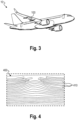
- Fig. 3 illustrates an exemplary aircraft 10 comprising the structural part 100 as described herein.
- the structural part 100 may form a stringer, a wing shell, a wing, a flap shell, a flap, a vertical stabilizer shell, a vertical stabilizer, or the like, of the aircraft 10, wherein this is not limited here.
- Fig. 4 illustrates a schematic micrograph of a structural part 400 with disturbed fiber courses according to prior art. It is intended to further illustrate the function of the at least one ply 120 during curing.
- the structural part 400 is in the form of a laminate comprising a number of layers 410.
- the structural part 400 of Fig. 4 does not comprise something like the at least one ply 120 described herein.
- the number of layers 410 and/or the fibers of the fiber-reinforced composite of the laminate are displaced and the fiber courses are disturbed, e.g. undulated.
- a resin of the laminate and/or fiber-reinforced composite may flow (with respect to Fig. 4 ) upward at this location because it is not held back.
- the structural part 100 described herein (as shown, e.g., in the schematic micrograph of Fig. 1 ) has an improved quality with respect thereto.
Landscapes
- Engineering & Computer Science (AREA)
- Mechanical Engineering (AREA)
- Chemical & Material Sciences (AREA)
- Composite Materials (AREA)
- Textile Engineering (AREA)
- Aviation & Aerospace Engineering (AREA)
- Architecture (AREA)
- Civil Engineering (AREA)
- Structural Engineering (AREA)
- Moulding By Coating Moulds (AREA)
Abstract
The present invention relates to a structural part (100) for an aircraft (10). The structural part (100) is in the form of a laminate comprising a number of layers (110) of a fiber-reinforced composite, and comprising at least one ply (120) prefabricated of a fiber-reinforced composite and inserted between at least a portion of the number of layers (110). Further, the method relates to a method for providing such structural part (100).
Description
- The present invention relates to a structural part for an aircraft, spacecraft, or the like. Further, the present invention relates to a method for providing, e.g. manufacturing, a structural part for an aircraft. In addition, the present invention relates to an aircraft, spacecraft, or the like, comprising such structural part.
- For structural parts for an aircraft, spacecraft, or the like, made of a fiber-reinforced composite an undisturbed fiber course is desirable. The fiber course of such structural part can be checked, for example, by examining a micrograph, a sectional image, or the like to see whether fibers of the composite and/or layers of a laminate have been disturbed, e.g. have displaced, during the curing process, which might undesirably change the corresponding characteristics of the composite and/or material, such as stiffness, strength, etc. Such an undesired fiber course disturbance may then be considered when dimensioning the structural part, e.g. by considering a corresponding knock-down factor, or the like.
- One of the objects of the invention is to provide improved solutions for providing a structural part for an aircraft, or the like, with desired characteristics of the fiber-reinforced composite. The object is solved by the subject-matter of the appended independent claims. Further embodiments are set out in the appended dependent claims.
- According to a first aspect, there is provided a structural part for an aircraft, spacecraft, or the like. The structural part is in the form of a laminate comprising a number of layers of a fiber-reinforced composite. The structural part comprises at least one ply prefabricated of a fiber-reinforced composite and inserted between at least a portion of the number of layers.
- In this configuration, the at least one ply may serve several functions at the same time.
- For example, during a curing process of the laminate, the at least one ply may keep the number of layers, the fibers and/or a fiber course thereof, in particular in a thickness direction of the laminate, in a desired position and/or orientation with respect to a possible displacement, movement, etc. of the fibers. In other words, the at least one ply may form a kind of barrier, boundary, or the like for the fibers of the laminate and thus prevent, or at least mitigate, a disturbance of the course of the fibers. For example, the at least one ply may prevent a resin of the laminate and/or the fiber-reinforced composite from flowing by serving as a barrier or the like to the resin. It may have this effect, for example, in the thickness direction of the laminate, and in any other direction depending on its position and/or orientation within the laminate.
- In addition, the at least one ply can also serve or contribute to load carrying. Accordingly, any additional weight of the at least one ply may be at least partially compensated by a corresponding weight saving in the laminate. The structural part is simple to manufacture, since the at least one ply already inserted prior to curing makes further sacrificial layers, which could alternatively be provided during curing, or a multi-stage curing process, so-called cobonding, obsolete. The inserted at least one ply can be easily detected, for example, by examining a micrograph or the like. It can also be detected that the at least one ply ensures or at least contributes to the fact that the fiber course of the fiber-reinforced composite of the laminate is as undisturbed as possible. The structural part, as well as the method for providing the same as described herein, makes it possible to provide the structural part with layers of the laminate being as close as possible to the geometry specified by the design and can therefore bear the full load.
- For example, the fiber-reinforced composite of the laminate may be any composite having material characteristics that are suitable for aircraft design. This may be determined, for example, from material tables, material specifications, from experiments and/or tests, from literature, etc. The fiber-reinforced composite of the laminate may also be referred to as a first (fiber-reinforced) composite. The fiber-reinforced composite of the at least one ply may be any composite having material characteristics that are suitable for aircraft design. The fiber-reinforced composite of the at least one ply may also be referred to as a second (fiber-reinforced) composite. For example, it may have such material characteristics that it has sufficiently high strength, stiffness, or the like at a curing temperature of the fiber-reinforced composite of the laminate. This and the material characteristics may be determined, for example, from material tables, material specifications, from experiments and/or tests, from literature, etc. By way of example, the fiber-reinforced composite may comprise or may be based on fiberglass, carbon fiber, or the like. The fiber-reinforced composite of the laminate and the fiber-reinforced composite of the at least one ply may be the same composite or may differ from each other. Further, for instance, the at least one ply may be prefabricated and/or provided by using a suitable tool, such as a laminating device, a curing device, an autoclave or the like. In addition, the fiber-reinforced composite of the at least one ply and/or the at least one ply may have a higher hardness than the laminate.
- The structural part may be used in an aircraft, spacecraft, or the like.
- According to at least some embodiments, the at least one ply may be precured with respect to the number of layers. Thus, it may be provided already in an at least partially cured state and, in particular, may be provided in this at least partially cured state prior to curing of the fiber-reinforced composite of the laminate. Thus, it may prevent or at least reduce disturbance, such as an undesired movement, displacement, or the like, of the fiber course of the fiber-reinforced material of the laminate during curing.
- In at least some embodiments, the at least one ply may have or may be provided with a plate shape. For example, the at least one ply may first be manufactured as a plate, also with a larger size, and then brought to a desired size, for example, by means of a cutting process. By way of example, it may be cut to size by means of water jet cutting, laser cutting, mechanical cutting, or the like. Thus, the at least one ply has a simple design and can be easily processed.
- According to at least some embodiments, the at least one ply may be arranged in a planar manner with respect to a thickness direction of the laminate. For example, the at least one ply may extend two-dimensionally in a plane perpendicular to a thickness direction of the laminate. This may also be understood that the at least one ply may extend at least substantially parallel to the number of layers of the laminate. Thus, it may at least reduce or prevent undulation of the fibers or the like, particularly in the thickness direction of the laminate.
- In at least some embodiments, the at least one ply may have adhesive properties and/or characteristics. This may be included or provided for during prefabricating the at least one ply. This may further improve the overall structure, e.g. also the strength, stiffness, etc. of the structural part. In addition, this may also facilitate lamination.
- According to at least some embodiments, the at least one ply may comprise or may be in the form of a fabric. This may further improve the overall structure, e.g. also the strength, stiffness, etc. of the structural part. In addition, this may also facilitate lamination.
- In at least some embodiments, the structural part may be configured to form one of the following: a stringer, a wing shell, a wing, a flap shell, a flap, a vertical stabilizer shell, a vertical stabilizer, or the like of the aircraft, spacecraft, etc. The part has an at least largely undisturbed fiber course of the laminate, since the at least one ply at least reduces or prevents a displacement of the fiber course during the curing of the laminate.
- A second aspect provides a method for providing a structural part for an aircraft. The method may also be referred to as a manufacturing method for the structural part. The method comprises providing at least one ply that is prefabricated and/or precured of a fiber-reinforced composite. Further, the method comprises forming a laminate comprising a number of layers of a fiber-reinforced composite, wherein prior to or for curing the fiber-reinforced composite, the at least one ply is inserted between at least a portion of the number of layers.
- The method may serve for providing the structural part of the first aspect. Accordingly, the method may be implemented according to any one of the embodiments of the first aspect. The method improves process reliability in manufacturing the structural part. For example, inserting the at least one ply can at least partially prevent fibers of the laminate from being displaced during curing.
- Further, for example, the at least one ply may be prefabricated and/or provided by using a suitable tool, such as a laminating device, a curing device, an autoclave or the like. Then, for forming the laminate, the at least one ply may be inserted into a suitable tool, such as a laminating device, a curing device, an autoclave or the like, and inserted between at least a portion of the number of layers. There, it can act on the fibers of the fiber-reinforced composite for the laminate in such a way, particularly mechanically, that the fibers are held or kept in a desired position and/or orientation, particularly during curing the same. The may further comprise curing the laminate and/or the number of layers together with the inserted at least one ply.
- According to at least some embodiments, the at least one ply may be provided plate-shaped. For example, the at least one ply may first be manufactured as a plate, also with a larger size, and then brought to a desired size, for example, by means of a cutting process. By way of example, it may be cut to size by means of water jet cutting, laser cutting, mechanical cutting, or the like. Thus, the at least one ply has a simple design and can be easily processed.
- In at least some embodiments, the at least one ply may be inserted to be arranged in a planar manner with respect to a thickness direction of the laminate. For example, the at least one ply may extend two-dimensionally in a plane perpendicular to a thickness direction of the laminate. This may also be understood that the at least one ply may extend at least substantially parallel to the number of layers of the laminate. Thus, it may at least reduce or prevent undulation of the fibers or the like, particularly in the thickness direction of the laminate.
- According to at least some embodiments, before inserting the at least one ply, it may be determined where in the laminate a disturbed fiber course may occur after curing. The at least one ply may be inserted there, i.e. at the respective location within the laminate based on the determination. For example, an appropriate positioning of the at least one ply may be determined based on calculation, modeling, based on experiments and/or tests, examination of micrographs, etc.
- In at least some embodiments, multiple prefabricated and/or precured plies may be provided and inserted. Optionally, the multiple plies may be inserted with multiple different fiber courses of the respective fiber-reinforced composite. This allows further improving the fiber course of the structural part.
- According to at least some embodiments, the at least one ply, when provided, may be cured only to a curing degree below a target curing degree of the structural part. The at least one ply may then complete curing together with the laminate after the insertion. For example, it may be up to e.g. 50% to 90% cured when provided and then only completely cured. In other words, the curing process of the at least one ply may be a two-stage process, with a first curing process before providing or during prefabrication and a second curing process after insertion into and curing of the laminate.
- In at least some embodiments, the at least one ply may be inserted between at least one base layer and at least one stringer layer of the laminate. For example, the base layer may serve as a skin or the like on which one or more stringers are to be cured. The proposed method improves the fiber course and thus the part quality in e.g. stringers, thickness variations, etc.
- According to a third aspect, there is provided an aircraft, spacecraft, or the like. The aircraft, spacecraft, etc. comprises at least one structural part according to the first aspect. Additionally or alternatively, aircraft, spacecraft, etc. comprises a structural part that is provided using the method according to the second aspect.
- The above configurations and refinements may be combined with one another as desired where expedient. Further possible embodiments, refinements and implementations of the invention also encompass combinations, which are not explicitly mentioned, of features of the invention described above or below with regard to the exemplary embodiments. In particular, a person skilled in the art will also add individual aspects as improvements or additions to the respective basic form of the present invention.
- The present invention is explained in more detail below with reference to the embodiments shown in the schematic figures:
- Fig. 1
- illustrates a schematic micrograph of a structural part according to an embodiment or being manufactured according to an embodiment.
- Fig. 2
- illustrates a part of a curing device, wherein at least one prefabricated and/or precured ply is inserted into a laminate to be cured, according to an embodiment.
- Fig. 3
- illustrates an exemplary aircraft comprising a structural part according to an embodiment.
- Fig. 4
- illustrates a schematic micrograph of a structural part with disturbed fiber courses according to prior art.
- In the figures of the drawing, elements, features and components which are identical, functionally identical and of identical action are denoted in each case by the same reference designations unless stated otherwise.
-
Fig. 1 illustrates a schematic micrograph of at least a section of astructural part 100 for an aircraft, spacecraft, or the like. Merely by way of example, thestructural part 100 is configured to form a stringer, a wing shell, a wing, a flap shell, a flap, a vertical stabilizer shell, a vertical stabilizer, or the like, wherein this is not limited here. - The
structural part 100 is in the form of or comprises a laminate that comprises or is formed by a number oflayers 110 of a fiber-reinforced composite.Fig. 1 illustrates in principle the number oflayers 110 and/or, at least exemplarily, the fiber course of the fiber-reinforced composite of the laminate and/or the number oflayers 110. Further, thestructural part 100 comprises at least oneply 120 that is prefabricated of a fiber-reinforced composite and inserted between at least a portion of the number oflayers 110. That is, the at least oneply 120 is additionally inserted into the laminate. As exemplarily shown, the at least oneply 120 may be arranged in a planar manner with respect to a thickness direction of the laminate. - From
Fig. 1 , it can be seen that the fiber course of the laminate and/or the number oflayer 110 is at least substantially undisturbed. This is achieved by the at least oneply 120 already being or having been placed into the laminate and/or into and/or between the number oflayers 110 prior to or for a curing process of the laminate, i.e. curing of its fiber-reinforced composite and/or the number oflayers 110. That is, during the curing process of the laminate, the at least oneply 120 has already been inserted, i.e. placed and/or arranged with in the laminate and/or the number oflayers 110, and a disturbance of the fiber course that could be caused through the curing process, e.g. by displacement and/or movement of one or more of the number oflayers 110, has at least been reduced or at least largely prevented. - In at least some embodiments, the at least one
ply 110 may be precured with respect to the number oflayers 110. Further, by way of example, the at least oneply 120 may have a plate shape, wherein other shapes are also conceivable depending on the design of thestructural part 100. the at least one ply () has adhesive properties. In addition, the at least one ply may comprise or may be in the form of a fabric. -
Fig. 2 illustrates roughly schematically a part of acuring device 200 and/or laminate device that can be used as a tool for manufacturing thestructural part 100. The at least oneply 120 is effective in particular during the curing process of the laminate and/or its fiber-reinforced composite and/or its number oflayers 110. As described above, the at least oneply 120 is additionally inserted into the laminate, as indicated inFig. 2 , even before the curing process of the of the laminate and/or its fiber-reinforced composite and/or its number oflayers 110. Due to its, for example, hardness, strength, etc., the at least oneply 120 acts like a barrier, mold holder, or the like, and at least substantially prevents the number oflayers 110 from shifting, moving, displacing, or the like. - With reference to
Fig. 2 , a method for providing, e.g., manufacturing, thestructural part 100 will now be explained. - The method comprises providing the at least one
ply 110 that is prefabricated and/or precured of a fiber-reinforced composite. Further, the method comprises forming the laminate comprising the number oflayers 110 of a fiber-reinforced composite. Prior to or for curing the laminate and/or its fiber-reinforced composite and/or the number oflayers 110, the at least oneply 120 is inserted between at least a portion of the number oflayers 110. That is, during the curing process, the at least oneply 120 is already inserted into the (to-be-formed) laminate. For example, the at least oneply 120 may be precured with respect to the number oflayers 110. The method may further comprise curing the laminate and/or the number oflayers 110 together with the inserted at least oneply 120. - Further, for example, the at least one ply may be prefabricated and/or provided by using a suitable tool, such as a laminating device, the
exemplary curing device 200 ofFig. 2 , an autoclave, or the like. Then, for forming the laminate, the at least one ply may be inserted into the laminate and/or inserted between at least a portion of the number of layers. There, it can act on the fibers of the fiber-reinforced composite for the laminate in such a way, particularly mechanically, that the fibers are held in a desired position and/or orientation, i.e. a desired fiber course, particularly during curing the same. - In addition, before inserting the at least one
ply 120, it may be determined where in the laminate a disturbed fiber course may occur after curing. The at least oneply 120 may be inserted there, i.e. at the respective location within the laminate based on the determination. For example, an appropriate positioning of the at least one ply may be determined based on calculation, modeling, based on experiments and/or tests, examination of micrographs (cf.Fig. 4 ), etc. -
Fig. 3 illustrates anexemplary aircraft 10 comprising thestructural part 100 as described herein. Merely by way of example, thestructural part 100 may form a stringer, a wing shell, a wing, a flap shell, a flap, a vertical stabilizer shell, a vertical stabilizer, or the like, of theaircraft 10, wherein this is not limited here. -
Fig. 4 illustrates a schematic micrograph of astructural part 400 with disturbed fiber courses according to prior art. It is intended to further illustrate the function of the at least oneply 120 during curing. - Again, the
structural part 400 is in the form of a laminate comprising a number oflayers 410. In contrast to thestructural part 100 described herein, thestructural part 400 ofFig. 4 does not comprise something like the at least oneply 120 described herein. As a result, the number oflayers 410 and/or the fibers of the fiber-reinforced composite of the laminate are displaced and the fiber courses are disturbed, e.g. undulated. Especially in the middle of the micrograph there are distinct bulges and undulation. For example, a resin of the laminate and/or fiber-reinforced composite may flow (with respect toFig. 4 ) upward at this location because it is not held back. Thestructural part 100 described herein (as shown, e.g., in the schematic micrograph ofFig. 1 ) has an improved quality with respect thereto. -
- 10
- aircraft
- 100
- structural part
- 110
- layer(s)
- 120
- ply
- 200
- tool (e.g. curing device)
- 400
- structural part (prior art)
- 410
- layer(s) (prior art)
Claims (15)
- A structural part (100) for an aircraft (10), the structural part (100) being in the form of a laminate comprising a number of layers (110) of a fiber-reinforced composite, and comprising at least one ply (120) prefabricated of a fiber-reinforced composite and inserted between at least a portion of the number of layers (110).
- The structural part of claim 1, wherein the at least one ply (120) is precured with respect to the number of layers (110).
- The structural part of claim 1 or 2, wherein the at least one ply (120) has a plate shape.
- The structural part of any one of the preceding claims, wherein the at least one ply (120) is arranged in a planar manner with respect to a thickness direction of the laminate.
- The structural part of any one of the preceding claims, wherein the at least one ply (120) has adhesive properties.
- The structural part of any one of the preceding claims, wherein the at least one ply (120) comprises or is in the form of a fabric.
- The structural part of any one of the preceding claims, wherein the structural part (100) is configured to form one of the following: a stringer, a wing shell, a wing, a flap shell, a flap, a vertical stabilizer shell, a vertical stabilizer.
- A method for providing a structural part (100) for an aircraft (10), the method comprising:providing at least one ply (120), prefabricated and/or precured of a fiber-reinforced composite; andforming a laminate comprising a number of layers (110) of a fiber-reinforced composite, wherein prior to or for curing the fiber-reinforced composite, the at least one ply (120) is inserted between at least a portion of the number of layers (110).
- The method of claim 8, wherein the at least one ply (120) is provided plate-shaped.
- The method of claim 8 or 9, wherein the at least one ply (120) is inserted to be arranged in a planar manner with respect to a thickness direction of the laminate.
- The method of any one of claims 8 to 10, wherein before inserting the at least one ply (120) it is determined where in the laminate a disturbed fiber course may occur after curing, and the at least one ply (120) is inserted there based on the determination.
- The method of any one of claims 8 to 11, wherein multiple prefabricated and/or precured plies (120) are provided and inserted with multiple different fiber courses.
- The method of any one of claims 8 to 12, wherein the at least one ply (120), when provided, is cured only to a curing degree below a target curing degree of the structural part (100), and the at least one ply (120) then completes curing together with the laminate after the insertion.
- The method of any one of claims 8 to 13, further comprising curing the laminate and/or the number of layers (110) together with the inserted at least one ply (120).
- An aircraft, comprising at least one structural part (100) according to any one of claims 1 to 7 and/or provided using the method according to any one of claims 8 to 14.
Priority Applications (1)
| Application Number | Priority Date | Filing Date | Title |
|---|---|---|---|
| EP23175441.7A EP4467326A1 (en) | 2023-05-25 | 2023-05-25 | Structural part for an aircraft and method for providing a structural part |
Applications Claiming Priority (1)
| Application Number | Priority Date | Filing Date | Title |
|---|---|---|---|
| EP23175441.7A EP4467326A1 (en) | 2023-05-25 | 2023-05-25 | Structural part for an aircraft and method for providing a structural part |
Publications (1)
| Publication Number | Publication Date |
|---|---|
| EP4467326A1 true EP4467326A1 (en) | 2024-11-27 |
Family
ID=86604011
Family Applications (1)
| Application Number | Title | Priority Date | Filing Date |
|---|---|---|---|
| EP23175441.7A Pending EP4467326A1 (en) | 2023-05-25 | 2023-05-25 | Structural part for an aircraft and method for providing a structural part |
Country Status (1)
| Country | Link |
|---|---|
| EP (1) | EP4467326A1 (en) |
Citations (4)
| Publication number | Priority date | Publication date | Assignee | Title |
|---|---|---|---|---|
| US20140099477A1 (en) * | 2012-10-04 | 2014-04-10 | The Boeing Company | Composite structure having a stabilizing element |
| WO2014147222A2 (en) * | 2013-03-22 | 2014-09-25 | Hexcel Holding Gmbh | Improvements in or relating to fibre reinforced composites |
| US20190168481A1 (en) * | 2017-12-01 | 2019-06-06 | The Boeing Company | Methods for Making Composite Parts from Stacked Partially Cured Sublaminate Units |
| US20220033049A1 (en) * | 2020-07-29 | 2022-02-03 | The Boeing Company | Composite Fabric Hat Stringers having Interleafed Tape Plies |
-
2023
- 2023-05-25 EP EP23175441.7A patent/EP4467326A1/en active Pending
Patent Citations (4)
| Publication number | Priority date | Publication date | Assignee | Title |
|---|---|---|---|---|
| US20140099477A1 (en) * | 2012-10-04 | 2014-04-10 | The Boeing Company | Composite structure having a stabilizing element |
| WO2014147222A2 (en) * | 2013-03-22 | 2014-09-25 | Hexcel Holding Gmbh | Improvements in or relating to fibre reinforced composites |
| US20190168481A1 (en) * | 2017-12-01 | 2019-06-06 | The Boeing Company | Methods for Making Composite Parts from Stacked Partially Cured Sublaminate Units |
| US20220033049A1 (en) * | 2020-07-29 | 2022-02-03 | The Boeing Company | Composite Fabric Hat Stringers having Interleafed Tape Plies |
Similar Documents
| Publication | Publication Date | Title |
|---|---|---|
| CA2640218C (en) | Composite aircraft floor system | |
| Mouritz et al. | Review of applications for advanced three-dimensional fibre textile composites | |
| US20090121081A1 (en) | Composite Bulkhead and Skin Construction | |
| JPH04232400A (en) | Composite air wheel having improved shearing capacity | |
| US20170015401A1 (en) | Trussed structure | |
| EP2666622A1 (en) | Skin-stiffener transition assembly, method of manufacture and application of said skin-stiffener transition assembly | |
| US20040048027A1 (en) | Honeycomb cores for aerospace applications | |
| EP2130762A2 (en) | Wing and empennage leading edge structure made of thermoplastic material with a stiffened double-shell configuration | |
| US20130316148A1 (en) | Metal sheet-fiber reinforced composite laminate | |
| JP2010527303A (en) | Hybrid composite panel system and method | |
| US8893865B2 (en) | Impact absorbing structure, method for producing impact absorbing structure, and movable body | |
| CN104349888A (en) | Composite structure with low density core and composite stitched reinforcement | |
| JP2014144770A (en) | Box structures for carrying loads and methods of making the same | |
| US9034453B2 (en) | Reinforced aircraft fuselage panel and method of manufacture | |
| CN102470929B (en) | Leading edge structure, in particular for the air intake of the nacelle of an aircraft engine | |
| EP3530958A1 (en) | Fan rotor blade and method of manufacturing same | |
| US20130149475A1 (en) | Composite Core Densification | |
| BRPI0711824A2 (en) | reinforced hybrid structures and methods | |
| JP2010507530A (en) | Wing panel structure | |
| US9474339B2 (en) | Connecting device, assembly and method for manufacturing an assembly | |
| Kitano | Characteristics of carbon-fiber-reinforced plastics (CFRP) and associated challenges–focusing on carbon-fiber-reinforced thermosetting resins (CFRTS) for aircraft | |
| KR20160120270A (en) | Method for manufacturing hollow reinforcement structures intersecting one another | |
| JP2016182924A (en) | Aircraft structure, aircraft structure manufacturing method, and aircraft structure design information creation method | |
| CN102390129A (en) | Foam interlayer structure compound material and preparation method thereof | |
| US9592640B2 (en) | Method for curing shell components |
Legal Events
| Date | Code | Title | Description |
|---|---|---|---|
| PUAI | Public reference made under article 153(3) epc to a published international application that has entered the european phase |
Free format text: ORIGINAL CODE: 0009012 |
|
| STAA | Information on the status of an ep patent application or granted ep patent |
Free format text: STATUS: THE APPLICATION HAS BEEN PUBLISHED |
|
| AK | Designated contracting states |
Kind code of ref document: A1 Designated state(s): AL AT BE BG CH CY CZ DE DK EE ES FI FR GB GR HR HU IE IS IT LI LT LU LV MC ME MK MT NL NO PL PT RO RS SE SI SK SM TR |
|
| STAA | Information on the status of an ep patent application or granted ep patent |
Free format text: STATUS: REQUEST FOR EXAMINATION WAS MADE |
|
| 17P | Request for examination filed |
Effective date: 20250527 |