EP4467221A1 - Radial orientiertes modulares vorreinigungssystem - Google Patents
Radial orientiertes modulares vorreinigungssystem Download PDFInfo
- Publication number
- EP4467221A1 EP4467221A1 EP24178013.9A EP24178013A EP4467221A1 EP 4467221 A1 EP4467221 A1 EP 4467221A1 EP 24178013 A EP24178013 A EP 24178013A EP 4467221 A1 EP4467221 A1 EP 4467221A1
- Authority
- EP
- European Patent Office
- Prior art keywords
- particulate
- filtration assembly
- array
- tray
- cap
- Prior art date
- Legal status (The legal status is an assumption and is not a legal conclusion. Google has not performed a legal analysis and makes no representation as to the accuracy of the status listed.)
- Withdrawn
Links
Images








Classifications
-
- B—PERFORMING OPERATIONS; TRANSPORTING
- B01—PHYSICAL OR CHEMICAL PROCESSES OR APPARATUS IN GENERAL
- B01D—SEPARATION
- B01D45/00—Separating dispersed particles from gases or vapours by gravity, inertia, or centrifugal forces
- B01D45/12—Separating dispersed particles from gases or vapours by gravity, inertia, or centrifugal forces by centrifugal forces
- B01D45/16—Separating dispersed particles from gases or vapours by gravity, inertia, or centrifugal forces by centrifugal forces generated by the winding course of the gas stream, the centrifugal forces being generated solely or partly by mechanical means, e.g. fixed swirl vanes
-
- B—PERFORMING OPERATIONS; TRANSPORTING
- B01—PHYSICAL OR CHEMICAL PROCESSES OR APPARATUS IN GENERAL
- B01D—SEPARATION
- B01D50/00—Combinations of methods or devices for separating particles from gases or vapours
- B01D50/20—Combinations of devices covered by groups B01D45/00 and B01D46/00
-
- B—PERFORMING OPERATIONS; TRANSPORTING
- B04—CENTRIFUGAL APPARATUS OR MACHINES FOR CARRYING-OUT PHYSICAL OR CHEMICAL PROCESSES
- B04C—APPARATUS USING FREE VORTEX FLOW, e.g. CYCLONES
- B04C3/00—Apparatus in which the axial direction of the vortex flow following a screw-thread type line remains unchanged ; Devices in which one of the two discharge ducts returns centrally through the vortex chamber, a reverse-flow vortex being prevented by bulkheads in the central discharge duct
- B04C3/04—Multiple arrangement thereof
Definitions
- This disclosure relates to a radially oriented, modular pre-cleaner system.
- One aspect of the disclosure provides a filtration assembly including a frame and an array of particulate separation elements for removing particulates from air.
- the frame defines a plurality of sockets and including a particulate tray.
- Each particulate separation element of the array of particulate separation elements is disposed within a respective socket of the plurality of sockets and defines an inlet of the filtration assembly.
- the array of particulate separation elements are disposed within the frame in a radial array about a central axis of the filtration assembly.
- frame may further define a central opening in fluid communication with the array of particulate separation elements.
- the central opening defines an outlet of the filtration assembly.
- the central opening may be substantially coaxial with the central axis of the filtration assembly.
- a central axis of each particulate separation element in the array of particulate separation elements may be substantially perpendicular to the central axis of the filtration assembly.
- the array of particulate separation elements are disposed in a three-dimensional radial array about a central axis of the filtration assembly.
- a filtration assembly including a frame and an array of particulate separation elements.
- the frame defines a plurality of sockets.
- Each particulate separation element of the array of particulate separation elements is disposed within a respective socket within the frame in a radial array about a central axis of the filtration assembly.
- each particulate separation element of the array of particulate separation elements defines an inlet of the filtration assembly.
- the frame includes a particulate tray configured to collect the removed particulates.
- the frame may further include a cap and one or more spacers.
- the one or more spacers are disposed between the cap and the particulate tray.
- the cap, the one or more spacers, and the particulate tray may be axially aligned along the central axis of the filtration assembly. Additionally or alternatively, the cap, the one or more spacers, and the particulate tray are secured together via fasteners.
- the frame further defines a central opening in fluid communication with the array of particulate separation elements, the central opening defining an outlet of the filtration assembly.
- the central opening may be substantially coaxial with the central axis of the filtration assembly.
- a central axis of each particulate separation element in the array of particulate separation elements may be substantially perpendicular to the central axis of the filtration assembly.
- the array of particulate separation elements are disposed in a three-dimensional radial array about the central axis of the filtration assembly.
- Example configurations will now be described more fully with reference to the accompanying drawings.
- Example configurations are provided so that this disclosure will be thorough, and will fully convey the scope of the disclosure to those of ordinary skill in the art. Specific details are set forth such as examples of specific components, devices, and methods, to provide a thorough understanding of configurations of the present disclosure. It will be apparent to those of ordinary skill in the art that specific details need not be employed, that example configurations may be embodied in many different forms, and that the specific details and the example configurations should not be construed to limit the scope of the disclosure.
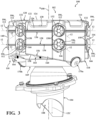
- a filtration system 10 includes a filtration assembly 100 and a vehicle body 200.
- air 12 e.g., engine exhaust air
- the filtration assembly 100 includes a pre-cleaner system 102 connected to an output duct 104, where the pre-cleaner system 102 forms an array of air inlets 106, 106a-n of the filtration assembly 100 and the output duct 104 forms a clean air outlet 108 of the filtration assembly 100.
- the vehicle body 200 includes an opening 202 extending through a thickness of the vehicle body 200 and configured to receive the output duct 104 of the filtration assembly 100.
- the pre-cleaner system 102 removes particulates 14 from the air 12 drawn through the air inlets 106 and retains removed particulates 14 while exhausting clean air 12C via the output duct 104, through the clean air outlet 108 to the vehicle engine.
- the pre-cleaner system 102 can be emptied when it is full of removed particulates 14 via cleanout ports 170a, 170b.
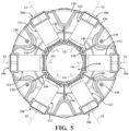
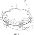
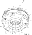
- the pre-cleaner system 102 includes a frame 110 and an array of particulate separation elements 112, 112a-n disposed within the frame 110.
- the frame 110 of the pre-cleaner system 102 is cylindrical, and includes the array of particulate separation elements 112 arranged in a stacked (i.e., three-dimensional) radial array about center axis A 100 of the filtration assembly 100.
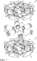
- the frame 110 is modular and includes a cap 114, a particulate tray 118, and one or more spacers 116 disposed between the cap 114 and the particulate tray 118.
- each of the components of the frame 110 include respective recesses (132, 134, 150, 152, 166, 168) that cooperate with adjacent recesses (132, 134, 150, 152, 166, 168) in the components of the frame 110 to form sockets.
- each socket formed by the adjacent recesses (132, 134, 150, 152, 166, 168) is sized to receive a respective particulate separation element 112 of the array of particulate separation elements 112. While FIGS.
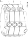
- FIGS. 6-8 and 16 illustrate a pre-cleaner system 102a having two (2) spacers 116a, 116b.
- FIG. 17 illustrates a pre-cleaner system 102b having three (3) spacers 116a, 116b, 116c.
- the pre-cleaner system 102 may not include any spacers 116, and instead the cap 114 may be directly coupled to the particulate tray 118.
- the cap 114 is generally cylindrical and includes a first end 120 and a second end 122 disposed on an opposite side of the cap 114 from the first end 120.
- the cap 114 further includes a top panel 124 disposed at the first end 120, a cap outer perimeter wall 126 extending from the top panel 124 at the first end 120 to the second end 122 of the cap 114, and a cap inner perimeter wall 128 spaced inward from the cap outer perimeter wall 126 and extending from the top panel 124 at the first end 120 to the second end 122 of the cap 114.
- the cap 114 additionally includes a plurality of cap outer recesses 132 formed through a thickness of the cap outer perimeter wall 126 and a plurality of cap inner recesses 134 formed through a thickness of the cap inner perimeter wall 128.
- the recesses 132, 134 extend from the second end 122 of the cap 114 and toward the first end 120 of the cap 114.
- the cap 114 includes a plurality of cap apertures 130 formed through a thickness of the top panel 124.
- the cap apertures 130 are configured to receive fasteners 171 that secures the cap 114, the spacer 116, and the particulate tray 118 of the frame 110 of the pre-cleaner system 102 together.
- the fasteners 171 include screw bolts and corresponding wingnuts; however, the fasteners 171 may include any implement for mechanically fixing the components of the frame 110 of the pre-cleaner system 102 together.
- the spacer 116 is generally cylindrical and includes a first end 136 and a second end 138 disposed on an opposite side of the spacer 116 from the first end 136.
- the spacer 116 further includes a spacer outer perimeter wall 140 extending from the first end 136 to the second end 138 of the spacer 116, and a spacer inner perimeter wall 142 spaced inward from the spacer outer perimeter wall 140 and extending the first end 136 to the second end 138 of the spacer 116.
- the spacer inner perimeter wall 142 defines a central opening 144 of the pre-cleaner system 102 in fluid communication with the output duct 104 through which clean air 12C flows.
- the spacer 116 further includes spokes 146 extending between and connecting the spacer outer perimeter wall 140 and the spacer inner perimeter wall 142.
- One or more of the spokes 146 may include respective spacer apertures 148 formed through a thickness of the spoke 146 (i.e., from the first end 136 of the spacer 116 to the second end 138 of the spacer 116).
- the spacer apertures 148 are configured to receive the fasteners 171 that secure the components of the pre-cleaner system 102 together.
- the spacer 116 additionally includes a plurality of spacer outer recesses 150 formed through a thickness of the spacer outer perimeter wall 140 and a plurality of spacer inner recesses 152 formed through a thickness of the spacer inner perimeter wall 142.
- a first set of recesses 150, 152 are formed in the first end 136 of the spacer 116 and extend toward the second end 138 of the spacer 116.
- a second set of recesses 150, 152 is axially aligned with the first set and are formed in the second end 138 of the spacer 116 and extend toward the first end 136 of the spacer 116.
- the particulate tray 118 additionally includes a plurality of particulate tray outer recesses 166 formed through a thickness of the particulate tray outer perimeter wall 160 and a plurality of particulate tray inner recesses 168 formed through a thickness of the particulate tray inner perimeter wall 162.
- the recesses 166, 168 extend from the first end 156 of the particulate tray 118 and toward the second end 154 of the particulate tray 118.
- the particulate tray 118 may include a plurality of particulate tray apertures 164 formed through a thickness of the bottom panel 158. As shown in FIGS.
- the particulate tray apertures 164 are configured to receive the fasteners 171 that secures the cap 114, the spacer 116, and the particulate tray 118 of the frame 110 of the pre-cleaner system 102 together.
- the particulate tray inner perimeter wall 162 defines a tray central opening 169 of the pre-cleaner system 102 that aligns with the central opening 144 formed through the spacer 116 and the clean air outlet 108 of the filtration assembly to channel clean air 12C into the vehicle body 200.
- the particulate tray 118 includes the cleanout ports 170a, 170b through which particulates 14 separated from the air 12 can be removed from the particulate tray 118.
- cap inner perimeter wall 128, the spacer inner perimeter wall 142, and the particulate tray inner perimeter wall 162 are aligned to allow clean air 12C to exit the pre-cleaner system 102, while particulates 14 separated from the air 12 fall to the particulate tray 118 and are collected in the bottom panel 158 of the particulate tray 118.
- each adjacent component i.e., the cap 114, the one or more spacers 116, the particulate tray 118
- each adjacent component cooperate with another adjacent component to form one or more sockets each sized to receive a particulate separation element 112 of the array of particulate separation elements 112.
- each cap outer recess 132 cooperates with an opposing spacer outer recess 150 and each cap inner recess 134 cooperates with an opposing spacer inner recess 152 to form a socket that receives a particulate separation element 112.
- each spacer outer recess 150 cooperates with an opposing particulate tray outer recess 166 and each spacer inner recess 152 cooperates with an opposing particulate tray inner recess 168 to form a socket that receives a particulate separation element 112.
- the particulate separation elements 112 are disposed within the pre-cleaner system 102 in a radial array about center axis A 100 of the filtration assembly 100.
- the pre-cleaner system 102 may include the array of particulate separation elements 112 that are designed to receive incoming air 12 from the environment (i.e., at the air inlets 106), and separately output particulates 14 and clean air 12C.
- the array of particulate separation elements 112 includes twelve particulate separation elements 112.
- each of the particulate separation elements 112 is disposed within the frame 110 of the pre-cleaner system 102 such that each particulate separation element 112 is connected to the pre-cleaner system 102 and operates in parallel.
- any combination of spacers 116 and particulate separation elements 112 may be used without departing from the scope of the present disclosure.
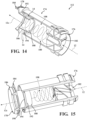
- the particulate separation element 112 is a cyclone filter having a tube-shaped body 174 that extends from a first end 176 to a second end 178 disposed on an opposite side of the body 174 than the first end 176 to define a cyclone cavity 180 defining a central axis A 112 of the particulate separation element 112.
- the first end 176 of the particulate separation element 112 generally corresponds to the air inlet 106 of the pre-cleaner system 102, and includes a guide vane 182 disposed within the cyclone cavity 180 that directs air 12 from the environment into the cyclone cavity 180.
- the second end 178 of the particulate separation element 112 includes a cap 184 having a cap outer flange 186 formed outside the cyclone cavity 180, and a cap inner conduit 188 disposed within the cyclone cavity 180.
- the particulate separation element 112 further includes an inner flange 192 spaced axially inward from the second end 178, which is sized to receive the cap inner conduit 188 of the cap 184 such that the cap 184 and the inner flange 192 cooperate to form a central opening 190 for the clean air 12C to exit the particulate separation element 112.
- the inner flange 192 includes a notch 194 formed through a thickness of the inner flange 192. The notch 194 in the inner flange 192 allows the separated particulates 14 to pass through the cap 184 to fall into the particulate tray 118.
- the air 12 enters the filtration assembly 100 axially via the air inlets 106 at the first end 176 of the particulate separation elements 112, where the guide vane 182 of each particulate separate element 112 directs the air in an axial and rotational direction within the cyclone cavity 180 toward the second end 178 of the body 174, creating a spiral vortex 198 flowing from the first end 176 of the body 174 to the central opening 190 disposed at the second end 178 of the body 174.
- the particulates 14 As the air 12 flows within the spiral vortex 198, the particulates 14, due to their mass and centrifugal force, are biased to the outer perimeter of the spiral vortex 198 and exit the particulate separation element 112 through the notch 194 in the inner flange 192, falling into the particulate tray 118 below the particulate separation element. As the particulates 14 are separated from the air 12 by the spiral vortex, the clean air 12C flows through the central opening 190 along the axis A 112 to the output duct 104 of the filtration assembly 100. When the particulate tray 118 is full of particulates 14, a user may empty the particulate tray 118 by sucking the particulates 14 out via a vacuum connected one or more of the cleanout ports 170a, 170b.
- the pre-cleaner system 102 can be modified to increase filtration capacity by simply adding additional sets of the spacers 116 and corresponding particulate separation elements 112 to the pre-cleaner system.
- This may be advantageous in instances where equipment that has been operated in a relatively clean environment (e.g., inside of a factory) is moved to a relatively dirty environment (e.g., outdoor construction site) and the filtration capacity for the filtration system 10 needs to be increased to account for dirtier air.
- the filtration system 10 can provide any level of filtration capacity using standard parts, thereby eliminating the need to design, manufacture, and inventory a wide variety of filter elements for different filtration capacities.
- first, second, third, etc. may be used herein to describe various elements, components, regions, layers and/or sections. These elements, components, regions, layers and/or sections should not be limited by these terms. These terms may be only used to distinguish one element, component, region, layer or section from another region, layer or section. Terms such as “first,” “second,” and other numerical terms do not imply a sequence or order unless clearly indicated by the context. Thus, a first element, component, region, layer or section discussed below could be termed a second element, component, region, layer or section without departing from the teachings of the example configurations.
Landscapes
- Chemical & Material Sciences (AREA)
- Chemical Kinetics & Catalysis (AREA)
- Filtering Of Dispersed Particles In Gases (AREA)
Applications Claiming Priority (2)
| Application Number | Priority Date | Filing Date | Title |
|---|---|---|---|
| US18/323,801 US20240390920A1 (en) | 2023-05-25 | 2023-05-25 | Radially oriented, modular pre-cleaner system |
| US202363507086P | 2023-06-08 | 2023-06-08 |
Publications (1)
| Publication Number | Publication Date |
|---|---|
| EP4467221A1 true EP4467221A1 (de) | 2024-11-27 |
Family
ID=91247965
Family Applications (1)
| Application Number | Title | Priority Date | Filing Date |
|---|---|---|---|
| EP24178013.9A Withdrawn EP4467221A1 (de) | 2023-05-25 | 2024-05-24 | Radial orientiertes modulares vorreinigungssystem |
Country Status (1)
| Country | Link |
|---|---|
| EP (1) | EP4467221A1 (de) |
Citations (5)
| Publication number | Priority date | Publication date | Assignee | Title |
|---|---|---|---|---|
| GB1278488A (en) * | 1968-06-28 | 1972-06-21 | Pall Corp | Vortex air cleaner assembly having uniform particle removal efficiency throughout the array of air cleaners |
| DE112010001706T5 (de) * | 2009-04-21 | 2012-11-08 | Mann + Hummel Gmbh | Modulares zyklonvorabscheidersystem und verfahren zu dessen herstellung |
| US8778043B2 (en) * | 2004-03-24 | 2014-07-15 | Donaldson Company, Inc. | Filter elements; air cleaner; assembly; and, methods |
| DE102015221492A1 (de) * | 2015-11-03 | 2017-05-04 | Mahle International Gmbh | Filtereinrichtung, insbesondere Zyklonabscheider |
| US11147423B2 (en) * | 2017-09-22 | 2021-10-19 | Lg Electronics Inc. | Dust collector and cleaner having the same |
-
2024
- 2024-05-24 EP EP24178013.9A patent/EP4467221A1/de not_active Withdrawn
Patent Citations (5)
| Publication number | Priority date | Publication date | Assignee | Title |
|---|---|---|---|---|
| GB1278488A (en) * | 1968-06-28 | 1972-06-21 | Pall Corp | Vortex air cleaner assembly having uniform particle removal efficiency throughout the array of air cleaners |
| US8778043B2 (en) * | 2004-03-24 | 2014-07-15 | Donaldson Company, Inc. | Filter elements; air cleaner; assembly; and, methods |
| DE112010001706T5 (de) * | 2009-04-21 | 2012-11-08 | Mann + Hummel Gmbh | Modulares zyklonvorabscheidersystem und verfahren zu dessen herstellung |
| DE102015221492A1 (de) * | 2015-11-03 | 2017-05-04 | Mahle International Gmbh | Filtereinrichtung, insbesondere Zyklonabscheider |
| US11147423B2 (en) * | 2017-09-22 | 2021-10-19 | Lg Electronics Inc. | Dust collector and cleaner having the same |
Similar Documents
| Publication | Publication Date | Title |
|---|---|---|
| US7462212B2 (en) | Cyclone dust separating apparatus for vacuum cleaner and vacuum cleaner having the same | |
| US8262761B2 (en) | Modular cyclone precleaner system and method | |
| EP1721556B1 (de) | Multi-Zyklon-Abscheider und Staubsauger mit demselben | |
| EP1714703B1 (de) | Zyklonabscheidevorrichtung und Staubsammelvorrichtung mit solch einer Abscheidevorrichtung | |
| CN1212097C (zh) | 用于吸尘器中旋风式集尘器的格栅组件 | |
| CN105268250B (zh) | 旋风分离器以及具有旋风分离器的过滤装置 | |
| EP1632163B1 (de) | Staubsauger mit Zyklon-Filter | |
| EP1842475B1 (de) | Zweite Sortiervorrichtung für einen Staubsauger | |
| US6884273B2 (en) | Multicell cyclone and method for producing it | |
| US9603498B2 (en) | Separating apparatus in a vacuum cleaner | |
| US7799106B2 (en) | Gas intake zone of a gas filter housing, used as a prefilter | |
| JP4520503B2 (ja) | サイクロン式分離装置 | |
| US20060230722A1 (en) | Multi-cyclone apparatus for vacuum cleaner | |
| EP1059993B1 (de) | Reinigungsvorrichtung | |
| EP1807169B1 (de) | Mit mehreren zyklonen versehene sammelvorrichtung | |
| WO2015114332A1 (en) | Separating apparatus in a vacuum cleaner | |
| GB2522659A (en) | Separating apparatus in a vacuum cleaner | |
| WO2015112010A1 (en) | A multi-cyclone dust separating apparatus | |
| US20190090709A1 (en) | Dust collector and cleaner having the same | |
| EP4467221A1 (de) | Radial orientiertes modulares vorreinigungssystem | |
| US20240390920A1 (en) | Radially oriented, modular pre-cleaner system | |
| GB2424605A (en) | Multi-cyclone apparatus for a vacuum cleaner | |
| GB2424606A (en) | Cyclonic dust-separating apparatus | |
| WO2024123479A1 (en) | Particulate separation system for laundry dryer |
Legal Events
| Date | Code | Title | Description |
|---|---|---|---|
| PUAI | Public reference made under article 153(3) epc to a published international application that has entered the european phase |
Free format text: ORIGINAL CODE: 0009012 |
|
| STAA | Information on the status of an ep patent application or granted ep patent |
Free format text: STATUS: THE APPLICATION HAS BEEN PUBLISHED |
|
| AK | Designated contracting states |
Kind code of ref document: A1 Designated state(s): AL AT BE BG CH CY CZ DE DK EE ES FI FR GB GR HR HU IE IS IT LI LT LU LV MC ME MK MT NL NO PL PT RO RS SE SI SK SM TR |
|
| STAA | Information on the status of an ep patent application or granted ep patent |
Free format text: STATUS: THE APPLICATION IS DEEMED TO BE WITHDRAWN |
|
| 18D | Application deemed to be withdrawn |
Effective date: 20250528 |