EP4467221A1 - Radially oriented, modular pre-cleaner system - Google Patents
Radially oriented, modular pre-cleaner system Download PDFInfo
- Publication number
- EP4467221A1 EP4467221A1 EP24178013.9A EP24178013A EP4467221A1 EP 4467221 A1 EP4467221 A1 EP 4467221A1 EP 24178013 A EP24178013 A EP 24178013A EP 4467221 A1 EP4467221 A1 EP 4467221A1
- Authority
- EP
- European Patent Office
- Prior art keywords
- particulate
- filtration assembly
- array
- tray
- cap
- Prior art date
- Legal status (The legal status is an assumption and is not a legal conclusion. Google has not performed a legal analysis and makes no representation as to the accuracy of the status listed.)
- Withdrawn
Links
Images








Classifications
-
- B—PERFORMING OPERATIONS; TRANSPORTING
- B01—PHYSICAL OR CHEMICAL PROCESSES OR APPARATUS IN GENERAL
- B01D—SEPARATION
- B01D45/00—Separating dispersed particles from gases or vapours by gravity, inertia, or centrifugal forces
- B01D45/12—Separating dispersed particles from gases or vapours by gravity, inertia, or centrifugal forces by centrifugal forces
- B01D45/16—Separating dispersed particles from gases or vapours by gravity, inertia, or centrifugal forces by centrifugal forces generated by the winding course of the gas stream, the centrifugal forces being generated solely or partly by mechanical means, e.g. fixed swirl vanes
-
- B—PERFORMING OPERATIONS; TRANSPORTING
- B01—PHYSICAL OR CHEMICAL PROCESSES OR APPARATUS IN GENERAL
- B01D—SEPARATION
- B01D50/00—Combinations of methods or devices for separating particles from gases or vapours
- B01D50/20—Combinations of devices covered by groups B01D45/00 and B01D46/00
-
- B—PERFORMING OPERATIONS; TRANSPORTING
- B04—CENTRIFUGAL APPARATUS OR MACHINES FOR CARRYING-OUT PHYSICAL OR CHEMICAL PROCESSES
- B04C—APPARATUS USING FREE VORTEX FLOW, e.g. CYCLONES
- B04C3/00—Apparatus in which the axial direction of the vortex flow following a screw-thread type line remains unchanged ; Devices in which one of the two discharge ducts returns centrally through the vortex chamber, a reverse-flow vortex being prevented by bulkheads in the central discharge duct
- B04C3/04—Multiple arrangement thereof
Definitions
- This disclosure relates to a radially oriented, modular pre-cleaner system.
- One aspect of the disclosure provides a filtration assembly including a frame and an array of particulate separation elements for removing particulates from air.
- the frame defines a plurality of sockets and including a particulate tray.
- Each particulate separation element of the array of particulate separation elements is disposed within a respective socket of the plurality of sockets and defines an inlet of the filtration assembly.
- the array of particulate separation elements are disposed within the frame in a radial array about a central axis of the filtration assembly.
- frame may further define a central opening in fluid communication with the array of particulate separation elements.
- the central opening defines an outlet of the filtration assembly.
- the central opening may be substantially coaxial with the central axis of the filtration assembly.
- a central axis of each particulate separation element in the array of particulate separation elements may be substantially perpendicular to the central axis of the filtration assembly.
- the array of particulate separation elements are disposed in a three-dimensional radial array about a central axis of the filtration assembly.
- a filtration assembly including a frame and an array of particulate separation elements.
- the frame defines a plurality of sockets.
- Each particulate separation element of the array of particulate separation elements is disposed within a respective socket within the frame in a radial array about a central axis of the filtration assembly.
- each particulate separation element of the array of particulate separation elements defines an inlet of the filtration assembly.
- the frame includes a particulate tray configured to collect the removed particulates.
- the frame may further include a cap and one or more spacers.
- the one or more spacers are disposed between the cap and the particulate tray.
- the cap, the one or more spacers, and the particulate tray may be axially aligned along the central axis of the filtration assembly. Additionally or alternatively, the cap, the one or more spacers, and the particulate tray are secured together via fasteners.
- the frame further defines a central opening in fluid communication with the array of particulate separation elements, the central opening defining an outlet of the filtration assembly.
- the central opening may be substantially coaxial with the central axis of the filtration assembly.
- a central axis of each particulate separation element in the array of particulate separation elements may be substantially perpendicular to the central axis of the filtration assembly.
- the array of particulate separation elements are disposed in a three-dimensional radial array about the central axis of the filtration assembly.
- Example configurations will now be described more fully with reference to the accompanying drawings.
- Example configurations are provided so that this disclosure will be thorough, and will fully convey the scope of the disclosure to those of ordinary skill in the art. Specific details are set forth such as examples of specific components, devices, and methods, to provide a thorough understanding of configurations of the present disclosure. It will be apparent to those of ordinary skill in the art that specific details need not be employed, that example configurations may be embodied in many different forms, and that the specific details and the example configurations should not be construed to limit the scope of the disclosure.
- a filtration system 10 includes a filtration assembly 100 and a vehicle body 200.
- air 12 e.g., engine exhaust air
- the filtration assembly 100 includes a pre-cleaner system 102 connected to an output duct 104, where the pre-cleaner system 102 forms an array of air inlets 106, 106a-n of the filtration assembly 100 and the output duct 104 forms a clean air outlet 108 of the filtration assembly 100.
- the vehicle body 200 includes an opening 202 extending through a thickness of the vehicle body 200 and configured to receive the output duct 104 of the filtration assembly 100.
- the pre-cleaner system 102 removes particulates 14 from the air 12 drawn through the air inlets 106 and retains removed particulates 14 while exhausting clean air 12C via the output duct 104, through the clean air outlet 108 to the vehicle engine.
- the pre-cleaner system 102 can be emptied when it is full of removed particulates 14 via cleanout ports 170a, 170b.
- the pre-cleaner system 102 includes a frame 110 and an array of particulate separation elements 112, 112a-n disposed within the frame 110.
- the frame 110 of the pre-cleaner system 102 is cylindrical, and includes the array of particulate separation elements 112 arranged in a stacked (i.e., three-dimensional) radial array about center axis A 100 of the filtration assembly 100.
- the frame 110 is modular and includes a cap 114, a particulate tray 118, and one or more spacers 116 disposed between the cap 114 and the particulate tray 118.
- each of the components of the frame 110 include respective recesses (132, 134, 150, 152, 166, 168) that cooperate with adjacent recesses (132, 134, 150, 152, 166, 168) in the components of the frame 110 to form sockets.
- each socket formed by the adjacent recesses (132, 134, 150, 152, 166, 168) is sized to receive a respective particulate separation element 112 of the array of particulate separation elements 112. While FIGS.
- FIGS. 6-8 and 16 illustrate a pre-cleaner system 102a having two (2) spacers 116a, 116b.
- FIG. 17 illustrates a pre-cleaner system 102b having three (3) spacers 116a, 116b, 116c.
- the pre-cleaner system 102 may not include any spacers 116, and instead the cap 114 may be directly coupled to the particulate tray 118.
- the cap 114 is generally cylindrical and includes a first end 120 and a second end 122 disposed on an opposite side of the cap 114 from the first end 120.
- the cap 114 further includes a top panel 124 disposed at the first end 120, a cap outer perimeter wall 126 extending from the top panel 124 at the first end 120 to the second end 122 of the cap 114, and a cap inner perimeter wall 128 spaced inward from the cap outer perimeter wall 126 and extending from the top panel 124 at the first end 120 to the second end 122 of the cap 114.
- the cap 114 additionally includes a plurality of cap outer recesses 132 formed through a thickness of the cap outer perimeter wall 126 and a plurality of cap inner recesses 134 formed through a thickness of the cap inner perimeter wall 128.
- the recesses 132, 134 extend from the second end 122 of the cap 114 and toward the first end 120 of the cap 114.
- the cap 114 includes a plurality of cap apertures 130 formed through a thickness of the top panel 124.
- the cap apertures 130 are configured to receive fasteners 171 that secures the cap 114, the spacer 116, and the particulate tray 118 of the frame 110 of the pre-cleaner system 102 together.
- the fasteners 171 include screw bolts and corresponding wingnuts; however, the fasteners 171 may include any implement for mechanically fixing the components of the frame 110 of the pre-cleaner system 102 together.
- the spacer 116 is generally cylindrical and includes a first end 136 and a second end 138 disposed on an opposite side of the spacer 116 from the first end 136.
- the spacer 116 further includes a spacer outer perimeter wall 140 extending from the first end 136 to the second end 138 of the spacer 116, and a spacer inner perimeter wall 142 spaced inward from the spacer outer perimeter wall 140 and extending the first end 136 to the second end 138 of the spacer 116.
- the spacer inner perimeter wall 142 defines a central opening 144 of the pre-cleaner system 102 in fluid communication with the output duct 104 through which clean air 12C flows.
- the spacer 116 further includes spokes 146 extending between and connecting the spacer outer perimeter wall 140 and the spacer inner perimeter wall 142.
- One or more of the spokes 146 may include respective spacer apertures 148 formed through a thickness of the spoke 146 (i.e., from the first end 136 of the spacer 116 to the second end 138 of the spacer 116).
- the spacer apertures 148 are configured to receive the fasteners 171 that secure the components of the pre-cleaner system 102 together.
- the spacer 116 additionally includes a plurality of spacer outer recesses 150 formed through a thickness of the spacer outer perimeter wall 140 and a plurality of spacer inner recesses 152 formed through a thickness of the spacer inner perimeter wall 142.
- a first set of recesses 150, 152 are formed in the first end 136 of the spacer 116 and extend toward the second end 138 of the spacer 116.
- a second set of recesses 150, 152 is axially aligned with the first set and are formed in the second end 138 of the spacer 116 and extend toward the first end 136 of the spacer 116.
- the particulate tray 118 additionally includes a plurality of particulate tray outer recesses 166 formed through a thickness of the particulate tray outer perimeter wall 160 and a plurality of particulate tray inner recesses 168 formed through a thickness of the particulate tray inner perimeter wall 162.
- the recesses 166, 168 extend from the first end 156 of the particulate tray 118 and toward the second end 154 of the particulate tray 118.
- the particulate tray 118 may include a plurality of particulate tray apertures 164 formed through a thickness of the bottom panel 158. As shown in FIGS.
- the particulate tray apertures 164 are configured to receive the fasteners 171 that secures the cap 114, the spacer 116, and the particulate tray 118 of the frame 110 of the pre-cleaner system 102 together.
- the particulate tray inner perimeter wall 162 defines a tray central opening 169 of the pre-cleaner system 102 that aligns with the central opening 144 formed through the spacer 116 and the clean air outlet 108 of the filtration assembly to channel clean air 12C into the vehicle body 200.
- the particulate tray 118 includes the cleanout ports 170a, 170b through which particulates 14 separated from the air 12 can be removed from the particulate tray 118.
- cap inner perimeter wall 128, the spacer inner perimeter wall 142, and the particulate tray inner perimeter wall 162 are aligned to allow clean air 12C to exit the pre-cleaner system 102, while particulates 14 separated from the air 12 fall to the particulate tray 118 and are collected in the bottom panel 158 of the particulate tray 118.
- each adjacent component i.e., the cap 114, the one or more spacers 116, the particulate tray 118
- each adjacent component cooperate with another adjacent component to form one or more sockets each sized to receive a particulate separation element 112 of the array of particulate separation elements 112.
- each cap outer recess 132 cooperates with an opposing spacer outer recess 150 and each cap inner recess 134 cooperates with an opposing spacer inner recess 152 to form a socket that receives a particulate separation element 112.
- each spacer outer recess 150 cooperates with an opposing particulate tray outer recess 166 and each spacer inner recess 152 cooperates with an opposing particulate tray inner recess 168 to form a socket that receives a particulate separation element 112.
- the particulate separation elements 112 are disposed within the pre-cleaner system 102 in a radial array about center axis A 100 of the filtration assembly 100.
- the pre-cleaner system 102 may include the array of particulate separation elements 112 that are designed to receive incoming air 12 from the environment (i.e., at the air inlets 106), and separately output particulates 14 and clean air 12C.
- the array of particulate separation elements 112 includes twelve particulate separation elements 112.
- each of the particulate separation elements 112 is disposed within the frame 110 of the pre-cleaner system 102 such that each particulate separation element 112 is connected to the pre-cleaner system 102 and operates in parallel.
- any combination of spacers 116 and particulate separation elements 112 may be used without departing from the scope of the present disclosure.
- the particulate separation element 112 is a cyclone filter having a tube-shaped body 174 that extends from a first end 176 to a second end 178 disposed on an opposite side of the body 174 than the first end 176 to define a cyclone cavity 180 defining a central axis A 112 of the particulate separation element 112.
- the first end 176 of the particulate separation element 112 generally corresponds to the air inlet 106 of the pre-cleaner system 102, and includes a guide vane 182 disposed within the cyclone cavity 180 that directs air 12 from the environment into the cyclone cavity 180.
- the second end 178 of the particulate separation element 112 includes a cap 184 having a cap outer flange 186 formed outside the cyclone cavity 180, and a cap inner conduit 188 disposed within the cyclone cavity 180.
- the particulate separation element 112 further includes an inner flange 192 spaced axially inward from the second end 178, which is sized to receive the cap inner conduit 188 of the cap 184 such that the cap 184 and the inner flange 192 cooperate to form a central opening 190 for the clean air 12C to exit the particulate separation element 112.
- the inner flange 192 includes a notch 194 formed through a thickness of the inner flange 192. The notch 194 in the inner flange 192 allows the separated particulates 14 to pass through the cap 184 to fall into the particulate tray 118.
- the air 12 enters the filtration assembly 100 axially via the air inlets 106 at the first end 176 of the particulate separation elements 112, where the guide vane 182 of each particulate separate element 112 directs the air in an axial and rotational direction within the cyclone cavity 180 toward the second end 178 of the body 174, creating a spiral vortex 198 flowing from the first end 176 of the body 174 to the central opening 190 disposed at the second end 178 of the body 174.
- the particulates 14 As the air 12 flows within the spiral vortex 198, the particulates 14, due to their mass and centrifugal force, are biased to the outer perimeter of the spiral vortex 198 and exit the particulate separation element 112 through the notch 194 in the inner flange 192, falling into the particulate tray 118 below the particulate separation element. As the particulates 14 are separated from the air 12 by the spiral vortex, the clean air 12C flows through the central opening 190 along the axis A 112 to the output duct 104 of the filtration assembly 100. When the particulate tray 118 is full of particulates 14, a user may empty the particulate tray 118 by sucking the particulates 14 out via a vacuum connected one or more of the cleanout ports 170a, 170b.
- the pre-cleaner system 102 can be modified to increase filtration capacity by simply adding additional sets of the spacers 116 and corresponding particulate separation elements 112 to the pre-cleaner system.
- This may be advantageous in instances where equipment that has been operated in a relatively clean environment (e.g., inside of a factory) is moved to a relatively dirty environment (e.g., outdoor construction site) and the filtration capacity for the filtration system 10 needs to be increased to account for dirtier air.
- the filtration system 10 can provide any level of filtration capacity using standard parts, thereby eliminating the need to design, manufacture, and inventory a wide variety of filter elements for different filtration capacities.
- first, second, third, etc. may be used herein to describe various elements, components, regions, layers and/or sections. These elements, components, regions, layers and/or sections should not be limited by these terms. These terms may be only used to distinguish one element, component, region, layer or section from another region, layer or section. Terms such as “first,” “second,” and other numerical terms do not imply a sequence or order unless clearly indicated by the context. Thus, a first element, component, region, layer or section discussed below could be termed a second element, component, region, layer or section without departing from the teachings of the example configurations.
Landscapes
- Chemical & Material Sciences (AREA)
- Chemical Kinetics & Catalysis (AREA)
- Filtering Of Dispersed Particles In Gases (AREA)
Abstract
A filtration assembly includes a modular frame and an array of particulate separation elements for removing particulates from air. The frame defines a plurality of sockets and including a particulate tray. Each particulate separation element of the array of particulate separation elements is disposed within a respective socket of the plurality of sockets and defines an inlet of the filtration assembly. The modular frame is operable to be selectively modified to change the number of particulate separation elements received within the frame.
Description
- This disclosure relates to a radially oriented, modular pre-cleaner system.
- This section provides background information related to the present disclosure and is not necessarily prior art.
- Motor vehicles conventionally include an air filter for processing air within the motor vehicle system. Conventional air filters generally include at least one layer of very fine fabric placed within the flow of air to capture dirt and other debris from the air that passes through the filter media. There is a balance between the filter media size and throughput of air through the filter media. For example, a smaller filter media may be appropriate for a lower airflow. Alternatively, a larger filter media may accommodate increased airflow requirements. Thus, conventional media-based filtration systems may require a wide range of filter media types and sizes to accommodate varying filtration capacities associated with different filtration environments.
- One aspect of the disclosure provides a filtration assembly including a frame and an array of particulate separation elements for removing particulates from air. The frame defines a plurality of sockets and including a particulate tray. Each particulate separation element of the array of particulate separation elements is disposed within a respective socket of the plurality of sockets and defines an inlet of the filtration assembly.
- Implementations of the disclosure may include one or more of the following optional features. In some implementations, the particulate tray is configured to collect the removed particulates. In some examples, the frame further includes a cap and one or more spacers, the one or more spacers disposed between the cap and the particulate tray. In these examples, the cap, the one or more spacers, and the particulate tray may be axially aligned along a central axis of the filtration assembly. Additionally or alternatively, the cap, the one or more spacers, and the particulate tray may be secured together via fasteners.
- In some implementations, the array of particulate separation elements are disposed within the frame in a radial array about a central axis of the filtration assembly. In these implementations, frame may further define a central opening in fluid communication with the array of particulate separation elements. Here, the central opening defines an outlet of the filtration assembly. In these implementations, the central opening may be substantially coaxial with the central axis of the filtration assembly. Additionally or alternatively, a central axis of each particulate separation element in the array of particulate separation elements may be substantially perpendicular to the central axis of the filtration assembly. In some examples, the array of particulate separation elements are disposed in a three-dimensional radial array about a central axis of the filtration assembly.
- Another aspect of the disclosure provides a filtration assembly including a frame and an array of particulate separation elements. The frame defines a plurality of sockets. Each particulate separation element of the array of particulate separation elements is disposed within a respective socket within the frame in a radial array about a central axis of the filtration assembly.
- This aspect may include one or more of the following optional features. In some implementations, each particulate separation element of the array of particulate separation elements defines an inlet of the filtration assembly. In some examples, the frame includes a particulate tray configured to collect the removed particulates. In these examples, the frame may further include a cap and one or more spacers. Here, the one or more spacers are disposed between the cap and the particulate tray. The cap, the one or more spacers, and the particulate tray may be axially aligned along the central axis of the filtration assembly. Additionally or alternatively, the cap, the one or more spacers, and the particulate tray are secured together via fasteners.
- In some implementations, the frame further defines a central opening in fluid communication with the array of particulate separation elements, the central opening defining an outlet of the filtration assembly. In these implementations, the central opening may be substantially coaxial with the central axis of the filtration assembly. Additionally or alternatively, a central axis of each particulate separation element in the array of particulate separation elements may be substantially perpendicular to the central axis of the filtration assembly. In some examples, the array of particulate separation elements are disposed in a three-dimensional radial array about the central axis of the filtration assembly.
- The details of one or more implementations of the disclosure are set forth in the accompanying drawings and the description below. Other aspects, features, and advantages will be apparent from the description and drawings, and from the claims.
-
-
FIG. 1 is a top perspective view of the filtration system according to the present disclosure. -
FIG. 2 is a bottom perspective view of the filtration system ofFIG. 1 . -
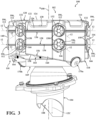
FIG. 3 is a front perspective view of a filtration assembly of the filtration system ofFIG. 1 . -
FIG. 4 is a partial front perspective view of the filtration assembly of the filtration system ofFIG. 1 . -
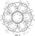
FIG. 5 is a partial top view of the filtration assembly of the filtration system ofFIG. 1 . -
FIG. 6 is a partial top perspective view of a frame and array of particulate separation elements of the filtration system ofFIG. 1 . -
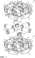
FIG. 7 is an exploded perspective view of the frame and the array of particulate separation elements ofFIG. 6 . -
FIG. 8 is an exploded partial perspective view of the filtration assembly of the filtration system ofFIG. 1 . -
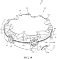
FIG. 9 is a top perspective view of a filtration assembly of the filtration system ofFIG. 1 . -
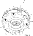
FIG. 10 is a bottom perspective view of a filtration assembly of the filtration system ofFIG. 1 . -
FIG. 11 is a front cross-sectional view of the filtration assembly ofFIG. 9 taken along the line 11-11 inFIG. 9 . -
FIGS. 12 and 13 are side perspective views of a particulate separation element of the filtration system ofFIG. 1 . -
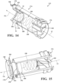
FIGS. 14 and 15 are partial side perspective views of the particulate separation element of the filtration system ofFIG. 1 . -
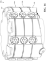
FIG. 16 is a front perspective view of a filtration assembly of the filtration system ofFIG. 1 . -
FIG. 17 is a front perspective view of a filtration assembly of the filtration system ofFIG. 1 . - Corresponding reference numerals indicate corresponding parts throughout the drawings.
- Example configurations will now be described more fully with reference to the accompanying drawings. Example configurations are provided so that this disclosure will be thorough, and will fully convey the scope of the disclosure to those of ordinary skill in the art. Specific details are set forth such as examples of specific components, devices, and methods, to provide a thorough understanding of configurations of the present disclosure. It will be apparent to those of ordinary skill in the art that specific details need not be employed, that example configurations may be embodied in many different forms, and that the specific details and the example configurations should not be construed to limit the scope of the disclosure.
- Referring to
FIGS. 1 and2 , afiltration system 10 is illustrated and includes afiltration assembly 100 and avehicle body 200. Briefly, and as described in more detail below, during operation of a vehicle, air 12 (e.g., engine exhaust air) is drawn through thefiltration system 10 as the engine runs, through thefiltration assembly 100, and into an air intake of the engine of the vehicle. Thefiltration assembly 100 includes apre-cleaner system 102 connected to anoutput duct 104, where thepre-cleaner system 102 forms an array ofair inlets 106, 106a-n of thefiltration assembly 100 and theoutput duct 104 forms aclean air outlet 108 of thefiltration assembly 100. Thevehicle body 200 includes anopening 202 extending through a thickness of thevehicle body 200 and configured to receive theoutput duct 104 of thefiltration assembly 100. As shown inFIGS. 1-3 , thepre-cleaner system 102 removesparticulates 14 from theair 12 drawn through theair inlets 106 and retains removedparticulates 14 while exhaustingclean air 12C via theoutput duct 104, through theclean air outlet 108 to the vehicle engine. Advantageously, and as discussed in further detail below, rather than replacing a filter media when it is full of removedparticulates 14, thepre-cleaner system 102 can be emptied when it is full of removedparticulates 14 viacleanout ports - Referring to
FIGS. 1-4 , thepre-cleaner system 102 includes aframe 110 and an array ofparticulate separation elements 112, 112a-n disposed within theframe 110. In the illustrated example, theframe 110 of thepre-cleaner system 102 is cylindrical, and includes the array ofparticulate separation elements 112 arranged in a stacked (i.e., three-dimensional) radial array about center axis A100 of thefiltration assembly 100. Theframe 110 is modular and includes acap 114, aparticulate tray 118, and one ormore spacers 116 disposed between thecap 114 and theparticulate tray 118. As will be discussed further below, each of the components of the frame 110 (i.e., the cap, the one ormore spacers 116, the particulate tray 118) include respective recesses (132, 134, 150, 152, 166, 168) that cooperate with adjacent recesses (132, 134, 150, 152, 166, 168) in the components of theframe 110 to form sockets. Here, each socket formed by the adjacent recesses (132, 134, 150, 152, 166, 168) is sized to receive a respectiveparticulate separation element 112 of the array ofparticulate separation elements 112. WhileFIGS. 1-4 show asingle spacer 116, due to the modularity of theframe 110 of thepre-cleaner system 102, it should be appreciated that any number ofspacers 116 may be included in theframe 110 to accommodate any number ofparticulate separation elements 112 in the array ofparticulate separation elements 112 based on the capacity needs of thefiltration system 10. For example,FIGS. 6-8 and16 illustrate apre-cleaner system 102a having two (2)spacers FIG. 17 illustrates apre-cleaner system 102b having three (3)spacers FIGS. 9-11 , thepre-cleaner system 102 may not include anyspacers 116, and instead thecap 114 may be directly coupled to theparticulate tray 118. - With reference to
FIGS. 3 and4 , thecap 114 is generally cylindrical and includes afirst end 120 and asecond end 122 disposed on an opposite side of thecap 114 from thefirst end 120. Thecap 114 further includes atop panel 124 disposed at thefirst end 120, a capouter perimeter wall 126 extending from thetop panel 124 at thefirst end 120 to thesecond end 122 of thecap 114, and a capinner perimeter wall 128 spaced inward from the capouter perimeter wall 126 and extending from thetop panel 124 at thefirst end 120 to thesecond end 122 of thecap 114. Thecap 114 additionally includes a plurality of capouter recesses 132 formed through a thickness of the capouter perimeter wall 126 and a plurality of capinner recesses 134 formed through a thickness of the capinner perimeter wall 128. In particular, therecesses second end 122 of thecap 114 and toward thefirst end 120 of thecap 114. Additionally, thecap 114 includes a plurality ofcap apertures 130 formed through a thickness of thetop panel 124. As shown inFIGS. 3 ,5 , and9 , thecap apertures 130 are configured to receivefasteners 171 that secures thecap 114, thespacer 116, and theparticulate tray 118 of theframe 110 of thepre-cleaner system 102 together. As shown, thefasteners 171 include screw bolts and corresponding wingnuts; however, thefasteners 171 may include any implement for mechanically fixing the components of theframe 110 of thepre-cleaner system 102 together. - Like the
cap 114, thespacer 116 is generally cylindrical and includes afirst end 136 and asecond end 138 disposed on an opposite side of thespacer 116 from thefirst end 136. Thespacer 116 further includes a spacerouter perimeter wall 140 extending from thefirst end 136 to thesecond end 138 of thespacer 116, and a spacerinner perimeter wall 142 spaced inward from the spacerouter perimeter wall 140 and extending thefirst end 136 to thesecond end 138 of thespacer 116. As shown, the spacerinner perimeter wall 142 defines acentral opening 144 of thepre-cleaner system 102 in fluid communication with theoutput duct 104 through whichclean air 12C flows. Thespacer 116 further includesspokes 146 extending between and connecting the spacerouter perimeter wall 140 and the spacerinner perimeter wall 142. One or more of thespokes 146 may includerespective spacer apertures 148 formed through a thickness of the spoke 146 (i.e., from thefirst end 136 of thespacer 116 to thesecond end 138 of the spacer 116). Thespacer apertures 148 are configured to receive thefasteners 171 that secure the components of thepre-cleaner system 102 together. Thespacer 116 additionally includes a plurality of spacerouter recesses 150 formed through a thickness of the spacerouter perimeter wall 140 and a plurality of spacerinner recesses 152 formed through a thickness of the spacerinner perimeter wall 142. As shown, a first set ofrecesses first end 136 of thespacer 116 and extend toward thesecond end 138 of thespacer 116. Conversely, a second set ofrecesses second end 138 of thespacer 116 and extend toward thefirst end 136 of thespacer 116. - With continued reference to
FIGS. 3 and4 , theparticulate tray 118 is generally cylindrical and includes afirst end 154 and asecond end 156 disposed on an opposite side of theparticulate tray 118 from thefirst end 154. Theparticulate tray 118 further includes abottom panel 158 disposed at thesecond end 156, a particulate trayouter perimeter wall 160 extending from thebottom panel 158 at thesecond end 156 to thefirst end 154 of theparticulate tray 118, and a particulate trayinner perimeter wall 162 spaced inward from the particulate trayouter perimeter wall 160 and extending from thebottom panel 158 at thesecond end 156 to thefirst end 154 of theparticulate tray 118. Theparticulate tray 118 additionally includes a plurality of particulate trayouter recesses 166 formed through a thickness of the particulate trayouter perimeter wall 160 and a plurality of particulate trayinner recesses 168 formed through a thickness of the particulate trayinner perimeter wall 162. In particular, therecesses first end 156 of theparticulate tray 118 and toward thesecond end 154 of theparticulate tray 118. Additionally, theparticulate tray 118 may include a plurality ofparticulate tray apertures 164 formed through a thickness of thebottom panel 158. As shown inFIGS. 3 and10 , theparticulate tray apertures 164 are configured to receive thefasteners 171 that secures thecap 114, thespacer 116, and theparticulate tray 118 of theframe 110 of thepre-cleaner system 102 together. As shown, the particulate trayinner perimeter wall 162 defines a traycentral opening 169 of thepre-cleaner system 102 that aligns with thecentral opening 144 formed through thespacer 116 and theclean air outlet 108 of the filtration assembly to channelclean air 12C into thevehicle body 200. Additionally, theparticulate tray 118 includes thecleanout ports particulates 14 separated from theair 12 can be removed from theparticulate tray 118. - Referring to
FIGS. 3-8 , when thepre-cleaner system 102 is assembled, thecap apertures 130, thespacer apertures 148, and theparticulate tray apertures 164 are aligned to receive thefasteners 171. By lining up therespective apertures outer perimeter wall 126, the spacerouter perimeter wall 140, and the particulate trayouter perimeter wall 160 are also aligned and form a substantially flush outer wall of thepre-cleaner system 102. Further, the capinner perimeter wall 128, the spacerinner perimeter wall 142, and the particulate trayinner perimeter wall 162 are aligned to allowclean air 12C to exit thepre-cleaner system 102, whileparticulates 14 separated from theair 12 fall to theparticulate tray 118 and are collected in thebottom panel 158 of theparticulate tray 118. - As discussed briefly above, each adjacent component (i.e., the
cap 114, the one ormore spacers 116, the particulate tray 118) cooperate with another adjacent component to form one or more sockets each sized to receive aparticulate separation element 112 of the array ofparticulate separation elements 112. For example, as shown inFIGS. 3 and4 , each capouter recess 132 cooperates with an opposing spacerouter recess 150 and each capinner recess 134 cooperates with an opposing spacerinner recess 152 to form a socket that receives aparticulate separation element 112. Similarly, each spacerouter recess 150 cooperates with an opposing particulate trayouter recess 166 and each spacerinner recess 152 cooperates with an opposing particulate trayinner recess 168 to form a socket that receives aparticulate separation element 112. - As described above, the
particulate separation elements 112 are disposed within thepre-cleaner system 102 in a radial array about center axis A100 of thefiltration assembly 100. Thepre-cleaner system 102 may include the array ofparticulate separation elements 112 that are designed to receiveincoming air 12 from the environment (i.e., at the air inlets 106), and separatelyoutput particulates 14 andclean air 12C. As shown inFIGS. 1-4 and8 , the array ofparticulate separation elements 112 includes twelveparticulate separation elements 112. Here, each of theparticulate separation elements 112 is disposed within theframe 110 of thepre-cleaner system 102 such that eachparticulate separation element 112 is connected to thepre-cleaner system 102 and operates in parallel. However, as described above, due to the modularity of the pre-cleaner system 102 (via the spacers 116), any combination ofspacers 116 andparticulate separation elements 112 may be used without departing from the scope of the present disclosure. - Referring to
FIGS. 12-15 , theparticulate separation element 112 is a cyclone filter having a tube-shapedbody 174 that extends from afirst end 176 to asecond end 178 disposed on an opposite side of thebody 174 than thefirst end 176 to define acyclone cavity 180 defining a central axis A112 of theparticulate separation element 112. Thefirst end 176 of theparticulate separation element 112 generally corresponds to theair inlet 106 of thepre-cleaner system 102, and includes aguide vane 182 disposed within thecyclone cavity 180 that directsair 12 from the environment into thecyclone cavity 180. Thesecond end 178 of theparticulate separation element 112 includes acap 184 having a capouter flange 186 formed outside thecyclone cavity 180, and a capinner conduit 188 disposed within thecyclone cavity 180. Theparticulate separation element 112 further includes aninner flange 192 spaced axially inward from thesecond end 178, which is sized to receive the capinner conduit 188 of thecap 184 such that thecap 184 and theinner flange 192 cooperate to form acentral opening 190 for theclean air 12C to exit theparticulate separation element 112. As shown inFIGS. 14 and 15 , theinner flange 192 includes anotch 194 formed through a thickness of theinner flange 192. Thenotch 194 in theinner flange 192 allows the separatedparticulates 14 to pass through thecap 184 to fall into theparticulate tray 118. - As shown, the
guide vane 182 is configured to direct theair 12 into thecyclone cavity 180 in a substantially coaxial manner relative to the central axis A112 of theparticulate separation element 112, which is perpendicular to the central axis A100 of thefiltration assembly 100. During operation of thefiltration system 10, theair 12 enters thefiltration assembly 100 axially via theair inlets 106 at thefirst end 176 of theparticulate separation elements 112, where theguide vane 182 of each particulateseparate element 112 directs the air in an axial and rotational direction within thecyclone cavity 180 toward thesecond end 178 of thebody 174, creating aspiral vortex 198 flowing from thefirst end 176 of thebody 174 to thecentral opening 190 disposed at thesecond end 178 of thebody 174. As theair 12 flows within thespiral vortex 198, theparticulates 14, due to their mass and centrifugal force, are biased to the outer perimeter of thespiral vortex 198 and exit theparticulate separation element 112 through thenotch 194 in theinner flange 192, falling into theparticulate tray 118 below the particulate separation element. As theparticulates 14 are separated from theair 12 by the spiral vortex, theclean air 12C flows through thecentral opening 190 along the axis A112 to theoutput duct 104 of thefiltration assembly 100. When theparticulate tray 118 is full ofparticulates 14, a user may empty theparticulate tray 118 by sucking theparticulates 14 out via a vacuum connected one or more of thecleanout ports - The foregoing description provides various examples of a
filtration system 10 that is configured in a modular manner, whereby filtration capacity of thesystem 10 can be easily modified to account for different operational and environmental factors. For example, thepre-cleaner system 102 can be modified to increase filtration capacity by simply adding additional sets of thespacers 116 and correspondingparticulate separation elements 112 to the pre-cleaner system. This may be advantageous in instances where equipment that has been operated in a relatively clean environment (e.g., inside of a factory) is moved to a relatively dirty environment (e.g., outdoor construction site) and the filtration capacity for thefiltration system 10 needs to be increased to account for dirtier air. Thus, thefiltration system 10 can provide any level of filtration capacity using standard parts, thereby eliminating the need to design, manufacture, and inventory a wide variety of filter elements for different filtration capacities. - The foregoing description has been provided for purposes of illustration and description. It is not intended to be exhaustive or to limit the disclosure. Individual elements or features of a particular configuration are generally not limited to that particular configuration, but, where applicable, are interchangeable and can be used in a selected configuration, even if not specifically shown or described. The same may also be varied in many ways. Such variations are not to be regarded as a departure from the disclosure, and all such modifications are intended to be included within the scope of the disclosure.
- The terminology used herein is for the purpose of describing particular exemplary configurations only and is not intended to be limiting. As used herein, the singular articles "a," "an," and "the" may be intended to include the plural forms as well, unless the context clearly indicates otherwise. The terms "comprises," "comprising," "including," and "having," are inclusive and therefore specify the presence of features, steps, operations, elements, and/or components, but do not preclude the presence or addition of one or more other features, steps, operations, elements, components, and/or groups thereof. The method steps, processes, and operations described herein are not to be construed as necessarily requiring their performance in the particular order discussed or illustrated, unless specifically identified as an order of performance. Additional or alternative steps may be employed.
- When an element or layer is referred to as being "on," "engaged to," "connected to," "attached to," or "coupled to" another element or layer, it may be directly on, engaged, connected, attached, or coupled to the other element or layer, or intervening elements or layers may be present. In contrast, when an element is referred to as being "directly on," "directly engaged to," "directly connected to," "directly attached to," or "directly coupled to" another element or layer, there may be no intervening elements or layers present. Other words used to describe the relationship between elements should be interpreted in a like fashion (e.g., "between" versus "directly between," "adjacent" versus "directly adjacent," etc.). As used herein, the term "and/or" includes any and all combinations of one or more of the associated listed items.
- The terms first, second, third, etc. may be used herein to describe various elements, components, regions, layers and/or sections. These elements, components, regions, layers and/or sections should not be limited by these terms. These terms may be only used to distinguish one element, component, region, layer or section from another region, layer or section. Terms such as "first," "second," and other numerical terms do not imply a sequence or order unless clearly indicated by the context. Thus, a first element, component, region, layer or section discussed below could be termed a second element, component, region, layer or section without departing from the teachings of the example configurations.
Claims (20)
- A filtration assembly comprising:a modular frame defining a plurality of sockets and including a particulate tray; andan array of particulate separation elements for removing particulates from air, each particulate separation element of the array of particulate separation elements disposed within a respective socket of the plurality of sockets and defining an inlet of the filtration assembly.
- The filtration assembly of Claim 1, wherein the particulate tray is configured to collect the removed particulates.
- The filtration assembly of Claim 1, wherein the frame further includes a cap and one or more spacers, the one or more spacers disposed between the cap and the particulate tray.
- The filtration assembly of Claim 3, wherein the cap, the one or more spacers, and the particulate tray are axially aligned along a central axis of the filtration assembly.
- The filtration assembly of Claim 3, wherein the cap, the one or more spacers, and the particulate tray are secured together via fasteners.
- The filtration assembly of Claim 1, wherein the array of particulate separation elements are disposed within the frame in a radial array about a central axis of the filtration assembly.
- The filtration assembly of Claim 6, wherein the frame further defines a central opening in fluid communication with the array of particulate separation elements, the central opening defining an outlet of the filtration assembly.
- The filtration assembly of Claim 7, wherein the central opening is substantially coaxial with the central axis of the filtration assembly.
- The filtration assembly of Claim 7, wherein a central axis of each particulate separation element in the array of particulate separation elements is substantially perpendicular to the central axis of the filtration assembly.
- The filtration assembly of Claim 1, wherein the array of particulate separation elements are disposed in a three-dimensional radial array about a central axis of the filtration assembly.
- A filtration assembly comprising:a modular frame defining a plurality of sockets; andan array of particulate separation elements for removing particulates from air, each particulate separation element of the array of particulate separation elements disposed within a respective socket within the frame in a radial array about a central axis of the filtration assembly.
- The filtration assembly of Claim 11, wherein each particulate separation element of the array of particulate separation elements defines an inlet of the filtration assembly.
- The filtration assembly of Claim 11, wherein the frame includes a particulate tray configured to collect the removed particulates.
- The filtration assembly of Claim 13, wherein the frame further includes a cap and one or more spacers, the one or more spacers disposed between the cap and the particulate tray.
- The filtration assembly of Claim 14, wherein the cap, the one or more spacers, and the particulate tray are axially aligned along the central axis of the filtration assembly.
- The filtration assembly of Claim 14, wherein the cap, the one or more spacers, and the particulate tray are secured together via fasteners.
- The filtration assembly of Claim 11, wherein the frame further defines a central opening in fluid communication with the array of particulate separation elements, the central opening defining an outlet of the filtration assembly.
- The filtration assembly of Claim 17, wherein the central opening is substantially coaxial with the central axis of the filtration assembly.
- The filtration assembly of Claim 17, wherein a central axis of each particulate separation element in the array of particulate separation elements is substantially perpendicular to the central axis of the filtration assembly.
- The filtration assembly of Claim 11, wherein the array of particulate separation elements are disposed in a three-dimensional radial array about the central axis of the filtration assembly.
Applications Claiming Priority (2)
| Application Number | Priority Date | Filing Date | Title |
|---|---|---|---|
| US18/323,801 US20240390920A1 (en) | 2023-05-25 | 2023-05-25 | Radially oriented, modular pre-cleaner system |
| US202363507086P | 2023-06-08 | 2023-06-08 |
Publications (1)
| Publication Number | Publication Date |
|---|---|
| EP4467221A1 true EP4467221A1 (en) | 2024-11-27 |
Family
ID=91247965
Family Applications (1)
| Application Number | Title | Priority Date | Filing Date |
|---|---|---|---|
| EP24178013.9A Withdrawn EP4467221A1 (en) | 2023-05-25 | 2024-05-24 | Radially oriented, modular pre-cleaner system |
Country Status (1)
| Country | Link |
|---|---|
| EP (1) | EP4467221A1 (en) |
Citations (5)
| Publication number | Priority date | Publication date | Assignee | Title |
|---|---|---|---|---|
| GB1278488A (en) * | 1968-06-28 | 1972-06-21 | Pall Corp | Vortex air cleaner assembly having uniform particle removal efficiency throughout the array of air cleaners |
| DE112010001706T5 (en) * | 2009-04-21 | 2012-11-08 | Mann + Hummel Gmbh | MODULAR CYCLONARY SEPARATION SYSTEM AND METHOD FOR THE PRODUCTION THEREOF |
| US8778043B2 (en) * | 2004-03-24 | 2014-07-15 | Donaldson Company, Inc. | Filter elements; air cleaner; assembly; and, methods |
| DE102015221492A1 (en) * | 2015-11-03 | 2017-05-04 | Mahle International Gmbh | Filter device, in particular cyclone separator |
| US11147423B2 (en) * | 2017-09-22 | 2021-10-19 | Lg Electronics Inc. | Dust collector and cleaner having the same |
-
2024
- 2024-05-24 EP EP24178013.9A patent/EP4467221A1/en not_active Withdrawn
Patent Citations (5)
| Publication number | Priority date | Publication date | Assignee | Title |
|---|---|---|---|---|
| GB1278488A (en) * | 1968-06-28 | 1972-06-21 | Pall Corp | Vortex air cleaner assembly having uniform particle removal efficiency throughout the array of air cleaners |
| US8778043B2 (en) * | 2004-03-24 | 2014-07-15 | Donaldson Company, Inc. | Filter elements; air cleaner; assembly; and, methods |
| DE112010001706T5 (en) * | 2009-04-21 | 2012-11-08 | Mann + Hummel Gmbh | MODULAR CYCLONARY SEPARATION SYSTEM AND METHOD FOR THE PRODUCTION THEREOF |
| DE102015221492A1 (en) * | 2015-11-03 | 2017-05-04 | Mahle International Gmbh | Filter device, in particular cyclone separator |
| US11147423B2 (en) * | 2017-09-22 | 2021-10-19 | Lg Electronics Inc. | Dust collector and cleaner having the same |
Similar Documents
| Publication | Publication Date | Title |
|---|---|---|
| US7462212B2 (en) | Cyclone dust separating apparatus for vacuum cleaner and vacuum cleaner having the same | |
| US8262761B2 (en) | Modular cyclone precleaner system and method | |
| EP1721556B1 (en) | Multi-cyclone apparatus and vacuum cleaner having the same | |
| EP1714703B1 (en) | Cyclonic filter assembly and dust collecting apparatus having the same | |
| CN1212097C (en) | Grid member for cyclone dust collector in vacuum cleaner | |
| CN105268250B (en) | Cyclone separator and filter device with cyclone separator | |
| EP1632163B1 (en) | Vacuum Cleaner with cyclone filter | |
| EP1842475B1 (en) | A Second-Stage Separator Device For A Vacuum Cleaner | |
| US6884273B2 (en) | Multicell cyclone and method for producing it | |
| US9603498B2 (en) | Separating apparatus in a vacuum cleaner | |
| US7799106B2 (en) | Gas intake zone of a gas filter housing, used as a prefilter | |
| US20060230722A1 (en) | Multi-cyclone apparatus for vacuum cleaner | |
| US7815702B2 (en) | Multi cyclone collector | |
| WO2015114332A1 (en) | Separating apparatus in a vacuum cleaner | |
| GB2522659A (en) | Separating apparatus in a vacuum cleaner | |
| WO2024123479A1 (en) | Particulate separation system for laundry dryer | |
| US20190090709A1 (en) | Dust collector and cleaner having the same | |
| WO2009063167A2 (en) | Dust separator for vacuum cleaner | |
| US20240390920A1 (en) | Radially oriented, modular pre-cleaner system | |
| GB2424605A (en) | Multi-cyclone apparatus for a vacuum cleaner | |
| GB2424606A (en) | Cyclonic dust-separating apparatus | |
| WO2001024907A1 (en) | A device for the separation of particles from air and an air-cleaning assembly having such a device |
Legal Events
| Date | Code | Title | Description |
|---|---|---|---|
| PUAI | Public reference made under article 153(3) epc to a published international application that has entered the european phase |
Free format text: ORIGINAL CODE: 0009012 |
|
| STAA | Information on the status of an ep patent application or granted ep patent |
Free format text: STATUS: THE APPLICATION HAS BEEN PUBLISHED |
|
| AK | Designated contracting states |
Kind code of ref document: A1 Designated state(s): AL AT BE BG CH CY CZ DE DK EE ES FI FR GB GR HR HU IE IS IT LI LT LU LV MC ME MK MT NL NO PL PT RO RS SE SI SK SM TR |
|
| STAA | Information on the status of an ep patent application or granted ep patent |
Free format text: STATUS: THE APPLICATION IS DEEMED TO BE WITHDRAWN |
|
| 18D | Application deemed to be withdrawn |
Effective date: 20250528 |