EP4467015A1 - Atomiser and electronic atomisation device - Google Patents
Atomiser and electronic atomisation device Download PDFInfo
- Publication number
- EP4467015A1 EP4467015A1 EP23769808.9A EP23769808A EP4467015A1 EP 4467015 A1 EP4467015 A1 EP 4467015A1 EP 23769808 A EP23769808 A EP 23769808A EP 4467015 A1 EP4467015 A1 EP 4467015A1
- Authority
- EP
- European Patent Office
- Prior art keywords
- hollow
- atomiser
- elastic arms
- proximal end
- tubular element
- Prior art date
- Legal status (The legal status is an assumption and is not a legal conclusion. Google has not performed a legal analysis and makes no representation as to the accuracy of the status listed.)
- Pending
Links
Images




Classifications
-
- A—HUMAN NECESSITIES
- A24—TOBACCO; CIGARS; CIGARETTES; SIMULATED SMOKING DEVICES; SMOKERS' REQUISITES
- A24F—SMOKERS' REQUISITES; MATCH BOXES; SIMULATED SMOKING DEVICES
- A24F40/00—Electrically operated smoking devices; Component parts thereof; Manufacture thereof; Maintenance or testing thereof; Charging means specially adapted therefor
- A24F40/40—Constructional details, e.g. connection of cartridges and battery parts
-
- A—HUMAN NECESSITIES
- A24—TOBACCO; CIGARS; CIGARETTES; SIMULATED SMOKING DEVICES; SMOKERS' REQUISITES
- A24F—SMOKERS' REQUISITES; MATCH BOXES; SIMULATED SMOKING DEVICES
- A24F7/00—Mouthpieces for pipes; Mouthpieces for cigar or cigarette holders
- A24F7/02—Mouthpieces for pipes; Mouthpieces for cigar or cigarette holders with detachable connecting members
-
- A—HUMAN NECESSITIES
- A24—TOBACCO; CIGARS; CIGARETTES; SIMULATED SMOKING DEVICES; SMOKERS' REQUISITES
- A24F—SMOKERS' REQUISITES; MATCH BOXES; SIMULATED SMOKING DEVICES
- A24F40/00—Electrically operated smoking devices; Component parts thereof; Manufacture thereof; Maintenance or testing thereof; Charging means specially adapted therefor
- A24F40/10—Devices using liquid inhalable precursors
Definitions
- Embodiments of this application relate to the field of electronic atomisation technologies, and in particular, to an atomiser and an electronic atomisation device.
- tobacco is burned to produce tobacco smoke. Attempts are made to replace these tobacco-burning products by manufacturing products that release compounds without burning tobacco.
- an example of this type of products is a heating device that releases compounds by heating rather than burning materials.
- the materials may be tobacco or other non-tobacco products, and the non-tobacco products may or may not include nicotine.
- aerosol-providing products for example, electronic atomisation devices. These devices usually contain liquid, and the liquid is heated to be vaporized, to generate an inhalable aerosol.
- the liquid may contain nicotine, and/or aromatics, and/or aerosol-generation substances (such as glycerin).
- An embodiment of this application provides an atomiser, including: a proximal end and a distal end, facing away from each other in a longitudinal direction;
- the one or more elastic arms are configured to expand radially outwardly of the tubular element.
- the one or more elastic arms are at least partially configured to be arranged obliquely at an angle to the longitudinal direction.
- the fastening element further includes: a main body portion, at least partially surrounding and coupled to an outer surface of the tubular element, where the one or more elastic arms are configured to extend from the main body portion toward the distal end.
- an included angle between the one or more elastic arms and the main body portion is an obtuse angle.
- an included angle between the one or more elastic arms and the main body portion ranges from 150 degrees to 179 degrees.
- the one or more elastic arms have a length of 1 mm to 12 mm; and/or the one or more elastic arms have a thickness of 0.1 mm to 2 mm.
- the one or more elastic arms are configured to be curved.
- the one or more elastic arms include metals or alloys or organic polymers.
- the plurality of elastic arms are separated or discrete from each other.
- the mouthpiece assembly includes a seal element configured to seal an opening of the liquid storage cavity, and a spacing between adjacent elastic arms is configured to allow air in the liquid storage cavity to be discharged when the seal element enters the opening.
- a distance between two adjacent elastic arms of the plurality of elastic arms ranges from 0.1 mm to 2 mm.
- the mouthpiece assembly includes:
- the atomisation component includes:
- the tubular element includes a first portion, a second portion, and a third portion that are sequentially arranged from the proximal end to the distal end; an outer diameter of the first portion is smaller than an outer diameter of the second portion, and the outer diameter of the second portion is smaller than an outer diameter of the third portion; the fastening element is coupled to the first portion; and the atomisation component is accommodated and retained in the third portion.
- the mouthpiece assembly includes a seal element configured to seal an opening of the liquid storage cavity
- the tubular element includes a first portion and a second portion that are sequentially arranged from the proximal end to the distal end, an outer diameter of the first portion is smaller than an outer diameter of the second portion, and the seal element is configured to maintain a gap with the first portion to discharge air in the liquid storage cavity when entering the opening until being in contact with the second portion to seal the opening.
- Another embodiment of this application further provides an atomiser, including a proximal end and a distal end, facing away from each other in a longitudinal direction; a liquid storage cavity, configured to store a liquid substrate; an atomisation component, configured to atomise the liquid substrate to generate aerosols; a mouthpiece assembly, located at the proximal end and used for a user to draw in aerosols, where the mouthpiece assembly is internally provided with a first hollow and a second hollow that are sequentially arranged in the longitudinal direction, the first hollow is closer to the proximal end than the second hollow, and an inner diameter of the first hollow is greater than an inner diameter of the second hollow to define a first step between the first hollow and the second hollow; and a tubular element, at least partially defining an aerosol output channel that is configured to output aerosols to the mouthpiece assembly, where the tubular element is provided with one or more elastic arms extending toward the distal end, and the one or more elastic arms extend into the first hollow through the second hollow and abut against the first step
- an atomiser including: a main housing having a proximal end and a distal end; a liquid storage cavity, defined in the main housing and configured to store a liquid substrate, where the liquid storage cavity has an opening near the proximal end for injecting a liquid substrate; an atomisation component, configured to atomise the liquid substrate to generate aerosols; a mouthpiece assembly, connected to the proximal end and used for a user to draw in aerosols, where the mouthpiece assembly includes a seal element configured to seal the opening; and a tubular element, at least partially defining an aerosol output channel that is configured to output aerosols to the mouthpiece assembly, where the tubular element includes a first portion and a second portion that are sequentially arranged from the proximal end to the distal end, an outer diameter of the first portion is smaller than an outer diameter of the second portion, and a position at which the first portion and the second portion connect is longitudinally lower than an end surface of the proximal end of the main housing
- Another embodiment of this application further provides an electronic atomisation device, including an atomiser configured to atomise a liquid substrate to generate aerosols, and a power supply mechanism configured to supply power to the atomiser, where the atomiser includes the atomiser described above.
- the mouthpiece assembly abuts against the elastic arm that extends toward the distal end and that is of the fastening element, thereby forming a tight connection with the tubular element that outputs aerosols, which helps to stop removal or separation of the mouthpiece assembly.
- the electronic atomisation device includes: an atomiser 100, storing a liquid substrate and heating and atomising the liquid substrate to generate aerosols; and a power supply mechanism 200 supplying power to the atomiser 100.
- the atomiser 100 and the power supply mechanism 200 can be removably coupled to each other.
- the power supply mechanism 200 can be used to power the atomiser 100, so that the atomiser 100 atomises the liquid substrate to generate aerosols.
- the atomiser 100 is removably coupled to one end that is along a length direction and is included in the power supply mechanism 200.
- the power supply mechanism 200 includes an electrical contact 230. When the atomiser 100 is coupled to the power supply mechanism 200, the electrical contact 230 is configured to form an electrical connection with the atomiser 100 to further provide power to the atomiser 100.
- the atomiser 100 is at least partially raised, and when coupled to the power supply mechanism 200, the raised portion of the atomiser 100 extends into the power supply mechanism 200, thereby forming a detachable coupling.
- the power supply mechanism 200 is internally provided with a seal piece 260 to provide seal when the atomiser 100 is coupled to the power supply mechanism 200.
- the seal piece 260 is configured to extend along a cross section direction of the power supply mechanism 200, and is preferably prepared by a flexible material such as silica gel, so as to prevent a liquid substrate seeped from the atomiser 100 from flowing to parts inside the power supply mechanism 200 such as a circuit board 220 and a gas flow sensor 250.
- the power supply mechanism 200 further includes a battery cell 210, configured to supply power; and the circuit board 220, disposed between the battery cell 210 and the electrical contact 230.
- the circuit board 220 operably guides a current between the battery cell 210 and the electrical contact 230.
- the power supply mechanism 200 includes the gas flow sensor 250, such as a microphone and an air pressure sensor, configured to sense inhalation airflow generated on the atomiser 100 during inhalation on the atomiser 100 by a user, so that the circuit board 220 controls the battery cell 210 to output power based on a detection signal of the gas flow sensor 250.
- the gas flow sensor 250 such as a microphone and an air pressure sensor, configured to sense inhalation airflow generated on the atomiser 100 during inhalation on the atomiser 100 by a user, so that the circuit board 220 controls the battery cell 210 to output power based on a detection signal of the gas flow sensor 250.
- FIG. 1 another end of the power supply mechanism 200 facing away from the atomiser 100 is provided with a charging interface 240 that is configured to supply power to the battery cell 210.
- Embodiments in FIG. 2 to FIG. 5 are schematic diagrams of a structure of the atomiser 100 in FIG. 1 according to an embodiment.
- the atomiser 100 includes an outer main body or a plurality of parts inside an outer housing (which may be referred to as a housing).
- An overall design of the outer main body or the outer housing may vary, and a type or configuration of the outer main body that may define an overall size and shape of the atomiser 100 may vary.
- an elongate main body may be formed by a single unitary housing, or an elongate housing may be formed by two or more separable main bodies.
- the outer main body or the outer housing may be formed by a metal or alloy such as stainless steel and aluminum.
- the outer main body or the outer housing is substantially circular in shape.
- the outer main body or the outer housing may have a generally cylindrical shape, or a generally elliptical cylindrical shape, or a generally flat cylindrical shape with its length greater than its width and its width greater than its thickness, or another regular or irregular shape.
- the atomiser 100 has a proximal end 110 and a distal end 120 that face away from each other in a longitudinal direction.
- the proximal end 110 is an end for vaping by a user
- the distal end 120 is an end configured to be coupled to the power supply mechanism 200.
- the outer main body or the outer housing of the atomiser 100 is jointly defined by a plurality of parts.
- the parts specifically defining the outer main body or the outer housing of the atomiser 100 include: a mouthpiece cap 30 close to and defining the proximal end 110, the first electrode 21 close to and defining the distal end 120, and a substantially tubular main housing 10 extending longitudinally between the mouthpiece cap 30 and the first electrode 21.
- the atomiser 100 is powered by an electrode assembly 20 close to and defining the distal end 120.
- the electrode assembly 20 forms an electrical connection with the electrical contact 230 when connected to the power supply mechanism 200 and further provides power to the atomiser 100.
- the electrode assembly 20 includes:
- a surface of the second electrode 22 at the distal end 120 is substantially flush with the second section 212 of the first electrode 21, and the second electrode 22 is at least partially exposed at the distal end 120, to facilitate contact and electrical connection between the second section 212 of the first electrode 21, the second electrode 22, and the power supply mechanism 200.
- the first section 211 of the first electrode 21 is further internally provided with an annular support wall 214 extending facing away from the second section 212. Insertion space 215 is defined between the first section 211 and the support wall 214.
- Insertion space 215 is defined between the first section 211 and the support wall 214.
- the electrode assembly 20 further includes: a seal element 80, substantially annular, for example, flexible silicone seal ring, located in the insertion space 215 and surrounding the support wall 214.
- the electrode assembly 20 further includes: an insulation element 23, substantially annular in shape, and located between the second section 212 of the first electrode 21 and the second electrode 22 to insulate the second section 212 and the second electrode 22.
- the insulation element 23 is, for example, an O-ring, a silicone ring, or the like.
- an air inlet hole 213 running, in a radial direction, through a part of the second section 212 of the first electrode 21 close to the first section 211 is further provided, to allow external air to enter the atomiser 100 during inhalation.
- the main housing 10 is internally provided with a plurality of parts for atomising and outputting a liquid substrate, specifically including: a tubular element 60, having a first portion 61, a second portion 62, and a third portion 63 that are sequentially arranged in the longitudinal direction. Outer diameters/inner diameters of the first portion 61, the second portion 62, and the third portion 63 gradually increase.
- the first portion 61 is toward or close to the proximal end 110 and the third portion 63 is toward or close to the distal end 120.
- an end of the tubular element 60 close to the electrode assembly 20 is at least partially extended between the seal element 80 and the support wall 214 and is supported or abutted by the first electrode 21 to form a stop.
- a liquid storage cavity 12 configured to store a liquid substrate is defined and formed between an outer surface of the tubular element 60 and an inner surface of the main housing 10.
- an end of the liquid storage cavity 12 facing the distal end 120 is sealed by the first electrode 21 and the seal element 80.
- the third portion 63 of the tubular element 60 is provided with at least one or more liquid guide holes 631 for allowing the liquid substrate in the liquid storage cavity 12 to enter the third portion 63.
- the third portion 63 of the tubular element 60 is also provided with an atomisation component 70, configured to at least partially receive the liquid substrate entering from the liquid guide hole 631, and heat and atomise the liquid substrate to generate aerosols for inhalation.
- the atomisation component 70 includes a porous body 71, in some implementations, such as porous ceramics, or porous glass, porous metal foam, or in other implementations, such as porous cotton, fiber cotton, sponge, or porous fiber.
- the porous body 71 is configured in a tubular shape extending longitudinally and substantially coaxially with the tubular element 60.
- An outer surface of the porous body 71 in a radial direction is at least partially in fluid communication with the liquid storage cavity 12 through the liquid guide hole 631 and is further used as a liquid absorbing surface to absorb the liquid substrate.
- An inner surface of the porous body 71 in the radial direction is used as an atomisation surface and is provided with a heating element 72 for heating and atomising the liquid substrate transferred to the heating element 72 through capillary channels in the porous body 71 to generate aerosols. The aerosols are released from the atomisation surface.
- the liquid substrate passes from the liquid storage cavity 12 through the liquid guide hole 631, then is provided to the outer surface of the porous body 71 for absorption, and infiltrates or is transferred, through the capillary channels in the porous body 71, to the heating element 72 for heating and atomisation.
- the third portion 63 of the tubular element 60 is further internally provided with:
- the upper seal element 74 spaces apart from the lower seal element 75, so that a portion of the outer surface of the porous body 71 located between the upper seal element 74 and the lower seal element 75 is exposed, so as to absorb the liquid substrate.
- An internal hollow between the first portion 61 and the second portion 62 of the tubular element 60 is mainly configured to define an aerosol output channel configured to output aerosols.
- the atomiser 100 further includes a mouthpiece assembly, used for a user to draw in aerosols.
- the mouthpiece assembly includes:
- the connecting portion 41 is configured to connect the connecting element 40 and the mouthpiece cap 30.
- the connecting portion 41 of the connecting element 40 extends into the first plugging portion 321 of the plugging slot 32 of the mouthpiece cap 30, and the connecting portion 41 abuts against the step 323 of the plugging slot 32 to form a stop.
- the connecting portion 41 is riveted into the first plugging portion 321 of the plugging slot 32 of the mouthpiece cap 30, or glue is applied between the connecting portion 41 and the first plugging portion 321 of the plugging slot 32, so that the connecting portion 41 and the mouthpiece cap 30 are tightly connected to each other.
- the connecting portion 43 after assembly, extends into the main housing 10 from an upper end of the main housing 10 and is connected to the tubular element 60.
- the mouthpiece assembly further includes a seal element 44, located between the connecting portion 43 and the main housing 10, to seal the connecting portion 43 and the main housing 10.
- outer diameters of the connecting portion 41 and the connecting portion 43 are both larger than an outer diameter of the extending portion 42, so that a recess or groove surrounding the extending portion 42 is formed on a surface of the connecting element 40.
- the mouthpiece assembly further includes a seal element 45, for example, a silicone ring or a silicone ring, fitted in the recess or groove defined by the extending portion 42.
- a seal element 45 for example, a silicone ring or a silicone ring, fitted in the recess or groove defined by the extending portion 42.
- FIG. 6 shows a state after the connecting element 40 and the mouthpiece cap 30 are assembled and connected.
- the connecting portion 41 of the connecting element 40 is inserted into the mouthpiece cap 30 and is tightly connected to the mouthpiece cap 30.
- the connecting portion 43 of the connecting element 40 is located outside the mouthpiece cap 30.
- connection implementation methods include:
- the plurality of elastic arms 52 have a curved surface shape or a curved arc shape.
- the elastic arm 52 has a length dimension d1 of about 1 mm to 12 mm and a thickness of 0.1 mm to 2 mm.
- a width dimension d2 of the notch or the gap 53 is 0.1 mm to 2 mm.
- An extension length d3 of the main body portion 51 is 2 mm to 4 mm.
- an extension length d1 of the elastic arm 52 is greater than the extension length d3 of the main body portion 51, and a diameter of the main body portion 51 ranges from 2 mm to 10 mm.
- the elastic arm 52 has an inclined portion 521 close to the main body portion 51 and a front end portion 522 facing away from the main body portion 51.
- the inclined portion 521 is arranged obliquely at an angle to the axial direction.
- an included angle ⁇ formed between the inclined portion 521 and the main body portion 51 ranges from 150 degrees to 179 degrees and is an obtuse angle.
- the inclined portion 521 gradually expands outward in a direction facing away from the main body portion 51 instead of shrinking or narrowing inward.
- the front end portion 522 is disposed parallel to an axial direction rather than obliquely.
- the inclined portion 521 enables the elastic arm 52 made of metal, alloy, or engineering plastic to shrink or narrow inward during extrusion, and then return to outward expansion without the extrusion force.
- the main body portion 51 of the fastening element 50 is in close contact with and tightly connected to the first portion 61 of the tubular element 60.
- the elastic arm 52 is kept at a distance from the first portion 61 of the tubular element 60 and therefore is in non-contact with the first portion 61.
- the distance between the elastic arm 52 and the first portion 61 of the tubular element 60 changes along the radial direction.
- an internal hollow of the substantially tubular connecting element 40 includes at least: a first hollow 471 and a second hollow 472 that are adjacent and have different inner diameters, where the first hollow 471 is closer to the proximal end 110, an inner diameter of the first hollow 471 is larger than an inner diameter of the second hollow 472, so that a step 473 is formed between the first hollow 471 and the second hollow 472.
- the first portion 61 of the tubular element 60 passes through the inner hollow of the connecting element 40 and then is inserted into the second plugging portion 322 of the plugging slot 32 of the mouthpiece cap 30.
- the elastic arm 52 of the fastening element 50 passes through the second hollow 472 into the first hollow 471, and then, the front end portion 522 abuts against the step 473, so that the mouthpiece assembly is tightly connected to the tubular element 60, and the mouthpiece assembly is prevented from separating or removing from the main housing 10.
- the inner diameter of the second hollow 472 is slightly smaller than an outer diameter of the front end portion 522 of the elastic arm 52, and the inner diameter of the first hollow 471 is greater than or equal to the outer diameter of the front end portion 522 of the elastic arm 52, so that the elastic arm 52 is at least partially compressed or shrank inward when in the second hollow 472.
- the elastic arm 52 changes from the compressed or shrank state to an expanded state, and abuts against the step 473 to form a stop.
- the inner hollow of the connecting element 40 is further provided with a seal element 46, such as a silicone ring or a seal ring, to seal the tubular element 60 and the connecting element 40.
- a seal element 46 such as a silicone ring or a seal ring
- the mouthpiece assembly includes the seal element 44, the seal element 45, and the seal element 46 for sealing an opening of the liquid storage cavity, and the notch or the gap 53 between adjacent elastic arms 52 is configured to allow air in the liquid storage cavity to be discharged when the seal element 46 enters the opening.
- the tubular element 60 is made of a metal or alloy tube, such as a stainless steel tube, to form, through stretching manners such as elastic stretching and dynamic stretching, the first portion 61, the second portion 62, and the third portion 63 that have different inner diameters/outer diameters.
- the first portion 61 has a length of about 8 mm to 12 mm, an inner diameter of 1 mm to 3 mm, and a wall thickness of about 0.1 mm to 0.3 mm.
- the second portion 62 has a length of about 15 mm to 30 mm, an inner diameter of 2 mm to 6 mm, and a wall thickness of about 0.1 mm to 0.3 mm.
- the third portion 63 has a length of 10 mm to 15 mm, an inner diameter of 5 mm to 10 mm, and a wall thickness of about 0.1 mm to 0.3 mm.
- the mouthpiece assembly includes the seal element 44, the seal element 45, and the seal element 46 for sealing an opening of the liquid storage cavity.
- the seal element 44 and the seal element 45 are close to an end surface of the proximal end of the main housing 10, and the seal element 46 is spaced apart from the seal element 44 and the seal element 45 in the longitudinal direction.
- the tubular element 60 includes the first portion 61 and the second portion 62 that are sequentially arranged from the proximal end to the distal end.
- An outer diameter of the first portion 61 is smaller than an outer diameter of the second portion 62.
- a position at which the first portion 61 and the second portion 62 connect is longitudinally lower than an end surface of the proximal end of the main housing 10.
- the seal element 46 is configured to maintain a gap with the first portion 61 to discharge air in the liquid storage cavity when entering the opening until being in contact with an outer surface of the second portion 62 to seal the opening.
- the seal element 44 and the seal element 45 remains in contact with the proximal end of the main housing 10. In this way, that unnecessarily increasing the pressure in the liquid storage cavity causes liquid leakage can be avoided during the process of installing the mouthpiece assembly to the main housing.
- a structure of the porous body 71 of the atomisation component 70 includes: a through hole 711 axially running through the porous body 71, where the through hole 711 has an inner diameter of about 1 mm to 3 mm.
- the porous body 71 is formed by molding a moldable material such as porous ceramics around the heating element 72 such as a spiral heating coil and then integrally sintering.
- the porous body 71 has an extension length of about 5 mm to 10 mm. In a specific implementation, the porous body 71 has a length of 7.2 mm.
- the porous body 71 has a portion 712 with an increased outer diameter at a lower end close to the distal end 120, so that a step 713 is defined on the outer surface of the porous body 71.
- the portion 712 with an increased outer diameter has an axially extending positioning protrusion 715.
- the lower seal element 75 includes a radially inwardly extending abutment portion 751 and an axially extending seal portion 752. After assembly, the abutment portion 751 abuts against the step 713 for assembling and fixing.
- the seal portion 752 surrounds the portion 712 with an increased outer diameter and seals the lower end of the porous body 71 and the tubular element 60.
- the inner surface of the abutment portion 751 of the lower seal element 75 is provided with a positioning recess 753 for fitting with the positioning protrusion 715 to provide positioning when the lower seal element 75 is wrapped or sleeved on the lower end of the porous body 71.
- the positioning recess 753 fits with the positioning protrusion 715 to prevent the lower seal element 75 and the porous body 71 from rotating relative to each other after assembly.
- the portion 712 with an increased outer diameter has an outer diameter of 4.8 mm, and a part of the portion 712 with an increased outer diameter has an extension length of 1 mm to 2 mm.
- a surface of the portion 712 with an increased outer diameter is provided with an air recess 714 running through the portion 712 with an increased outer diameter.
- the air recess 714 is bent or circuitous. In a preferred implementation, the air recess 714 has a width of about 0.1 mm to 0.5 mm.
- air entering through the air inlet hole 213 can pass through the air recess 714, then enter a position between the upper seal element 74 and the lower seal element 75 in the third portion 63 of the tubular element 60, and then escape through the liquid guide hole 631 into the liquid storage cavity 12 to relieve negative pressure of the liquid storage cavity 12, as shown by an arrow R3 in FIG. 8 and FIG. 11 .
- the heating element 72 is a resistive heating coil or a solenoid coil.
- the heating element 72 is made of a resistive metal or an alloy material, such as commonly used iron-chromium-aluminum, nickel-chromium-aluminum, nickel-chromium, nickel-iron, silver-palladium, and stainless steel.
- the coil-structured heating element 72 has approximately 3 to 8 windings or turns.
- a diameter of a wire material of the coil-structured heating element 72 is 0.1 mm to 0.3 mm.
- An inner diameter of the coil-structured heating element 72 is substantially equal to an inner diameter of the through hole 711 of the porous body 71, and has an inner diameter of about 1 mm to 3 mm.
- the coil-structured heating element 72 has an axial extension length of 3 mm to 6 mm, preferably 3.2 mm to 4.5 mm.
- the coil-structured heating element 72 is completely embedded in an inner surface of the through hole 711 of the porous body 71. In some implementations, the coil-structured heating element 72 is at least partially exposed or protrudes from the inner surface of the through hole 711 of the porous body 71.
- a distance between adjacent windings or turns of the coil-structured heating element 72 is substantially constant in the axial direction.
- a distance between adjacent windings or turns of the coil-structured heating element 72 is about 0.5 mm to 1.0 mm, to facilitate preventing heat accumulation.
- a distance between adjacent windings or turns of the coil-structured heating element 72 varies in the axial direction.
- the distance between adjacent windings or turns gradually increases from two ends to the middle along the axial direction.
- a first wire 721 is connected to an upper end of the coil-structured heating element 72 to form electrical connection.
- a second wire 722 is connected to a lower end of the coil-structured heating element 72 to form electrical connection.
- the air recess 714 is obscured by the lower seal element 75.
- a channel for adding air to the liquid storage cavity 12 is formed between the lower seal element 75 and the porous body 71.
- the air recess 714 is formed on the inner surface or on an outer surface of the lower seal element 75.
- the heating element 72 abuts against or is connected to the first electrode 21 and the second electrode 22 through the elongated first wire 721 and the elongated second wire 722, separately, so as to power the heating element 22.
- the atomiser 100 further includes: a support base 76, supporting the atomisation component 70/the porous body 71 from the lower end.
- the support base 76 is at least partially accommodated and retained in the support wall 214 of the first electrode 21, and abuts against the support wall 214 to form a stop.
- a material of the support base 76 is preferably flexible silicone.
- the support base 76 is provided with a first wire hole 762 and a second wire hole 763.
- the first wire 721 passes through the first wire hole 762 and is connected to the first electrode 21 by abutment, contact, welding, or another manner.
- the second wire 722 passes through the second wire hole 763 and is connected to the second electrode 22 by abutment, contact, welding, or another manner.
- the support base 76 has a receiving cavity 764 opposite to the through hole 711 of the porous body 71 along the longitudinal direction, for receiving and retaining condensate after aerosols are condensed.
- the support base 76 has a hole 765 extending from an outer surface into the receiving cavity 764.
- the hole 765 is opposite to or in airflow communication with the air inlet hole 213 on the first electrode 21.
- an air flow path is shown by an arrow R2 in FIG. 4 , FIG. 13 , and FIG. 14 .
- External air enters the support base 76 through the air inlet hole 213 and the hole 765 in sequence, then passes through the through hole 711 of the porous body 71, and carries the aerosols to be output from the tubular element 60 to the channel 31 of the mouthpiece cap 30. The external air carrying the aerosols is finally inhaled at the air inhalation hole 111.
- the surface of the support base 76 further has a wall 761 protruding toward the distal end 120, facilitating surrounding and fixing of the first wire 721 passing through the support base 76, separating or separation or fixation of the first wire 721, preventing the first wire 721 from being in contact or entanglement with the second wire 722/the second electrode 22 due to bending or the like during assembly.
Landscapes
- Containers And Packaging Bodies Having A Special Means To Remove Contents (AREA)
Abstract
Description
- This application claims priority to
Chinese Patent Application No. 202210253182.8, filed with the China National Intellectual Property Administration on March 15, 2022 Chinese Patent Application No. 202211137791.3, filed with the China National Intellectual Property Administration on September 19, 2022 - Embodiments of this application relate to the field of electronic atomisation technologies, and in particular, to an atomiser and an electronic atomisation device.
- During use of tobacco products (such as cigarettes and cigars), tobacco is burned to produce tobacco smoke. Attempts are made to replace these tobacco-burning products by manufacturing products that release compounds without burning tobacco.
- An example of this type of products is a heating device that releases compounds by heating rather than burning materials. For example, the materials may be tobacco or other non-tobacco products, and the non-tobacco products may or may not include nicotine. As another example, there are aerosol-providing products, for example, electronic atomisation devices. These devices usually contain liquid, and the liquid is heated to be vaporized, to generate an inhalable aerosol. The liquid may contain nicotine, and/or aromatics, and/or aerosol-generation substances (such as glycerin).
- An embodiment of this application provides an atomiser, including: a proximal end and a distal end, facing away from each other in a longitudinal direction;
- a liquid storage cavity, configured to store a liquid substrate;
- an atomisation component, configured to atomise the liquid substrate to generate aerosols;
- a mouthpiece assembly, located at the proximal end and used for a user to draw in aerosols, where the mouthpiece assembly is internally provided with a first hollow and a second hollow that are sequentially arranged in the longitudinal direction, the first hollow is closer to the proximal end than the second hollow, and an inner diameter of the first hollow is greater than an inner diameter of the second hollow to define a first step between the first hollow and the second hollow;
- a tubular element, at least partially defining an aerosol output channel that is configured to output aerosols to the mouthpiece assembly; and
- a fastening element, coupled to the tubular element and having one or more elastic arms extending out toward the distal end, where the one or more elastic arms extend into the first hollow and abut against the first step, to tightly connect the mouthpiece assembly to the tubular element.
- In a preferred implementation, the one or more elastic arms are configured to expand radially outwardly of the tubular element.
- In a preferred implementation, the one or more elastic arms are at least partially configured to be arranged obliquely at an angle to the longitudinal direction.
- In a preferred implementation, the fastening element further includes:
a main body portion, at least partially surrounding and coupled to an outer surface of the tubular element, where the one or more elastic arms are configured to extend from the main body portion toward the distal end. - In a preferred implementation, an included angle between the one or more elastic arms and the main body portion is an obtuse angle.
- In a preferred implementation, an included angle between the one or more elastic arms and the main body portion ranges from 150 degrees to 179 degrees.
- In a preferred implementation, the one or more elastic arms have a length of 1 mm to 12 mm; and/or the one or more elastic arms have a thickness of 0.1 mm to 2 mm.
- In a preferred implementation, the one or more elastic arms are configured to be curved.
- In a preferred implementation, the one or more elastic arms include metals or alloys or organic polymers.
- In a preferred implementation, the plurality of elastic arms are separated or discrete from each other.
- In a preferred implementation, the mouthpiece assembly includes a seal element configured to seal an opening of the liquid storage cavity, and a spacing between adjacent elastic arms is configured to allow air in the liquid storage cavity to be discharged when the seal element enters the opening.
- In a preferred implementation, a distance between two adjacent elastic arms of the plurality of elastic arms ranges from 0.1 mm to 2 mm.
- In a preferred implementation, the mouthpiece assembly includes:
- a mouthpiece cap, at least partially defining an outer surface of the atomiser; and
- a connecting element, at least partially accommodated and retained in the mouthpiece cap, where the connecting element is configured in a tubular shape extending in the longitudinal direction, and the first hollow, the second hollow, and the step are surrounded and defined by an inner surface of the connecting element.
- In a preferred implementation, the atomisation component includes:
- a resistive heating coil, extending longitudinally for heating the liquid substrate to generate aerosols; and
- a porous body, surrounding the resistive heating coil and configured to receive the liquid substrate of the liquid storage cavity and transfer the liquid substrate to the resistive heating coil, where
- a distance between adjacent windings of the resistive heating coil ranges from 0.5 mm to 1.0 mm.
- In a preferred implementation, the tubular element includes a first portion, a second portion, and a third portion that are sequentially arranged from the proximal end to the distal end; an outer diameter of the first portion is smaller than an outer diameter of the second portion, and the outer diameter of the second portion is smaller than an outer diameter of the third portion; the fastening element is coupled to the first portion; and the atomisation component is accommodated and retained in the third portion.
- In a preferred implementation, the mouthpiece assembly includes a seal element configured to seal an opening of the liquid storage cavity, the tubular element includes a first portion and a second portion that are sequentially arranged from the proximal end to the distal end, an outer diameter of the first portion is smaller than an outer diameter of the second portion, and the seal element is configured to maintain a gap with the first portion to discharge air in the liquid storage cavity when entering the opening until being in contact with the second portion to seal the opening.
- Another embodiment of this application further provides an atomiser, including a proximal end and a distal end, facing away from each other in a longitudinal direction; a liquid storage cavity, configured to store a liquid substrate; an atomisation component, configured to atomise the liquid substrate to generate aerosols; a mouthpiece assembly, located at the proximal end and used for a user to draw in aerosols, where the mouthpiece assembly is internally provided with a first hollow and a second hollow that are sequentially arranged in the longitudinal direction, the first hollow is closer to the proximal end than the second hollow, and an inner diameter of the first hollow is greater than an inner diameter of the second hollow to define a first step between the first hollow and the second hollow; and a tubular element, at least partially defining an aerosol output channel that is configured to output aerosols to the mouthpiece assembly, where the tubular element is provided with one or more elastic arms extending toward the distal end, and the one or more elastic arms extend into the first hollow through the second hollow and abut against the first step, to prevent the mouthpiece assembly from being separated or removed from the tubular element.
- Another embodiment of this application further provides an atomiser, including: a main housing having a proximal end and a distal end; a liquid storage cavity, defined in the main housing and configured to store a liquid substrate, where the liquid storage cavity has an opening near the proximal end for injecting a liquid substrate; an atomisation component, configured to atomise the liquid substrate to generate aerosols; a mouthpiece assembly, connected to the proximal end and used for a user to draw in aerosols, where the mouthpiece assembly includes a seal element configured to seal the opening; and a tubular element, at least partially defining an aerosol output channel that is configured to output aerosols to the mouthpiece assembly, where the tubular element includes a first portion and a second portion that are sequentially arranged from the proximal end to the distal end, an outer diameter of the first portion is smaller than an outer diameter of the second portion, and a position at which the first portion and the second portion connect is longitudinally lower than an end surface of the proximal end of the main housing, where the seal element is configured to maintain a gap with the first portion to discharge air in the liquid storage cavity when entering the opening until being in contact with the second portion to seal the opening.
- Another embodiment of this application further provides an electronic atomisation device, including an atomiser configured to atomise a liquid substrate to generate aerosols, and a power supply mechanism configured to supply power to the atomiser, where the atomiser includes the atomiser described above.
- In the foregoing atomiser, the mouthpiece assembly abuts against the elastic arm that extends toward the distal end and that is of the fastening element, thereby forming a tight connection with the tubular element that outputs aerosols, which helps to stop removal or separation of the mouthpiece assembly.
- One or more embodiments are exemplarily described with reference to the corresponding figures in the accompanying drawings, and the descriptions are not to be construed as limiting embodiments. Elements in the accompanying drawings that have same reference numerals are represented as similar elements, and unless otherwise particularly stated, the figures in the accompanying drawings are not drawn to scale.
-
FIG. 1 is a schematic diagram of an electronic atomisation device according to an embodiment; -
FIG. 2 is a schematic diagram of an embodiment of an atomiser inFIG. 1 ; -
FIG. 3 is a schematic exploded view of the atomiser inFIG. 2 from a perspective; -
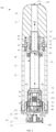
FIG. 4 is a schematic sectional view of the atomiser inFIG. 2 ; -
FIG. 5 is a schematic exploded view of the atomiser inFIG. 4 from a perspective; -
FIG. 6 is a schematic diagram of a mouthpiece assembly inFIG. 5 after assembly; -
FIG. 7 is a schematic diagram of an electrode assembly inFIG. 5 after assembly; -
FIG. 8 is a schematic diagram of a tubular element assembled with an atomisation component and a fastening element inFIG. 5 ; -
FIG. 9 is a view of a mouthpiece assembly assembled with a tubular element; -
FIG. 10 is a schematic diagram of a fastening element from another perspective; -
FIG. 11 is a schematic diagram of an atomisation component from another perspective; -
FIG. 12 is a schematic diagram of a lower seal element from another perspective; -
FIG. 13 is a schematic diagram of an atomisation component and a support element before assembly; and -
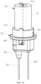
FIG. 14 is a schematic diagram of the atomisation component assembled with the support element inFIG. 13 . - For ease of understanding of this application, this application is described below in more detail with reference to the accompanying drawings and specific implementations.
- This application provides an electronic atomisation device. Refer to
FIG. 1 . The electronic atomisation device includes: anatomiser 100, storing a liquid substrate and heating and atomising the liquid substrate to generate aerosols; and apower supply mechanism 200 supplying power to theatomiser 100. - In an optional implementation, for example, as shown in
FIG. 1 , theatomiser 100 and thepower supply mechanism 200 can be removably coupled to each other. In addition, when coupled, thepower supply mechanism 200 can be used to power theatomiser 100, so that theatomiser 100 atomises the liquid substrate to generate aerosols. Specifically, theatomiser 100 is removably coupled to one end that is along a length direction and is included in thepower supply mechanism 200. Thepower supply mechanism 200 includes anelectrical contact 230. When theatomiser 100 is coupled to thepower supply mechanism 200, theelectrical contact 230 is configured to form an electrical connection with theatomiser 100 to further provide power to theatomiser 100. - According to the preferred embodiment shown in
FIG. 1 , theatomiser 100 is at least partially raised, and when coupled to thepower supply mechanism 200, the raised portion of theatomiser 100 extends into thepower supply mechanism 200, thereby forming a detachable coupling. - The
power supply mechanism 200 is internally provided with aseal piece 260 to provide seal when theatomiser 100 is coupled to thepower supply mechanism 200. In the preferred implementation shown inFIG. 1 , theseal piece 260 is configured to extend along a cross section direction of thepower supply mechanism 200, and is preferably prepared by a flexible material such as silica gel, so as to prevent a liquid substrate seeped from theatomiser 100 from flowing to parts inside thepower supply mechanism 200 such as acircuit board 220 and agas flow sensor 250. - In the preferred implementation shown in
FIG. 1 , thepower supply mechanism 200 further includes abattery cell 210, configured to supply power; and thecircuit board 220, disposed between thebattery cell 210 and theelectrical contact 230. Thecircuit board 220 operably guides a current between thebattery cell 210 and theelectrical contact 230. - The
power supply mechanism 200 includes thegas flow sensor 250, such as a microphone and an air pressure sensor, configured to sense inhalation airflow generated on theatomiser 100 during inhalation on theatomiser 100 by a user, so that thecircuit board 220 controls thebattery cell 210 to output power based on a detection signal of thegas flow sensor 250. - Further, in the preferred implementation shown in
FIG. 1 , another end of thepower supply mechanism 200 facing away from theatomiser 100 is provided with a charginginterface 240 that is configured to supply power to thebattery cell 210. - Embodiments in
FIG. 2 to FIG. 5 are schematic diagrams of a structure of theatomiser 100 inFIG. 1 according to an embodiment. Theatomiser 100 includes an outer main body or a plurality of parts inside an outer housing (which may be referred to as a housing). An overall design of the outer main body or the outer housing may vary, and a type or configuration of the outer main body that may define an overall size and shape of theatomiser 100 may vary. Typically, an elongate main body may be formed by a single unitary housing, or an elongate housing may be formed by two or more separable main bodies. In some examples, the outer main body or the outer housing may be formed by a metal or alloy such as stainless steel and aluminum. Other suitable materials include various plastics (for example, polycarbonate), a metal-plating over plastic (metal-plating over plastic), ceramics, and the like. In addition, the outer main body or the outer housing is substantially circular in shape. Alternatively, in yet other implementations, the outer main body or the outer housing may have a generally cylindrical shape, or a generally elliptical cylindrical shape, or a generally flat cylindrical shape with its length greater than its width and its width greater than its thickness, or another regular or irregular shape. - Further refer to
FIG. 2 to FIG. 5 . Theatomiser 100 has aproximal end 110 and adistal end 120 that face away from each other in a longitudinal direction. In use, theproximal end 110 is an end for vaping by a user, and thedistal end 120 is an end configured to be coupled to thepower supply mechanism 200. The outer main body or the outer housing of theatomiser 100 is jointly defined by a plurality of parts. The parts specifically defining the outer main body or the outer housing of theatomiser 100 include: amouthpiece cap 30 close to and defining theproximal end 110, thefirst electrode 21 close to and defining thedistal end 120, and a substantially tubularmain housing 10 extending longitudinally between themouthpiece cap 30 and thefirst electrode 21. - Further refer to
FIG. 3 to FIG. 5 andFIG. 7 . Theatomiser 100 is powered by anelectrode assembly 20 close to and defining thedistal end 120. Specifically, theelectrode assembly 20 forms an electrical connection with theelectrical contact 230 when connected to thepower supply mechanism 200 and further provides power to theatomiser 100. Specifically, theelectrode assembly 20 includes: - the
first electrode 21, configured in a longitudinally extending annular shape, and having afirst section 211 and asecond section 212 that have different outer diameters, where thesecond section 212 is closer to thedistal end 120 and defines thedistal end 120, and a surface of thesecond section 212 is provided with external threads for forming a detachable connection with matching internal threads on thepower supply mechanism 200; and - a
second electrode 22, substantially in an annular shape that is arranged coaxially with thefirst electrode 21, where thesecond electrode 22 is accommodated and retained in thesecond section 212 of thefirst electrode 21. Thefirst electrode 21 and thesecond electrode 22 are both made of metal or alloy with low resistivity, such as gold, silver, copper, nickel, or alloys including gold, silver, copper, and nickel. In use, one of thefirst electrode 21 and thesecond electrode 22 serves as a positive electrode, and the other serves as a negative electrode. - In addition, after assembly, a surface of the
second electrode 22 at thedistal end 120 is substantially flush with thesecond section 212 of thefirst electrode 21, and thesecond electrode 22 is at least partially exposed at thedistal end 120, to facilitate contact and electrical connection between thesecond section 212 of thefirst electrode 21, thesecond electrode 22, and thepower supply mechanism 200. - In addition, the
first section 211 of thefirst electrode 21 is further internally provided with anannular support wall 214 extending facing away from thesecond section 212.Insertion space 215 is defined between thefirst section 211 and thesupport wall 214. During assembly, a lower end part of themain housing 10 facing toward thedistal end 120 is inserted into theinsertion space 215 to form assembly and fixation. In a more preferred implementation, theelectrode assembly 20 further includes: aseal element 80, substantially annular, for example, flexible silicone seal ring, located in theinsertion space 215 and surrounding thesupport wall 214. When the lower end part of themain housing 10 is inserted into theinsertion space 215, theseal element 80 is radially squeezed or compressed by themain housing 10 and thesupport wall 214, to seal themain housing 10 and thesupport wall 214. - In addition, the
electrode assembly 20 further includes:
aninsulation element 23, substantially annular in shape, and located between thesecond section 212 of thefirst electrode 21 and thesecond electrode 22 to insulate thesecond section 212 and thesecond electrode 22. Theinsulation element 23 is, for example, an O-ring, a silicone ring, or the like. - In addition, an
air inlet hole 213 running, in a radial direction, through a part of thesecond section 212 of thefirst electrode 21 close to thefirst section 211 is further provided, to allow external air to enter theatomiser 100 during inhalation. - Further refer to
FIG. 3 to FIG. 5 andFIG. 8 . Themain housing 10 is internally provided with a plurality of parts for atomising and outputting a liquid substrate, specifically including:
atubular element 60, having afirst portion 61, asecond portion 62, and athird portion 63 that are sequentially arranged in the longitudinal direction. Outer diameters/inner diameters of thefirst portion 61, thesecond portion 62, and thethird portion 63 gradually increase. Thefirst portion 61 is toward or close to theproximal end 110 and thethird portion 63 is toward or close to thedistal end 120. - After assembly, an end of the
tubular element 60 close to theelectrode assembly 20 is at least partially extended between theseal element 80 and thesupport wall 214 and is supported or abutted by thefirst electrode 21 to form a stop. - After assembly, the
tubular element 60 is essentially accommodated and retained in themain housing 10. Aliquid storage cavity 12 configured to store a liquid substrate is defined and formed between an outer surface of thetubular element 60 and an inner surface of themain housing 10. In addition, an end of theliquid storage cavity 12 facing thedistal end 120 is sealed by thefirst electrode 21 and theseal element 80. - The
third portion 63 of thetubular element 60 is provided with at least one or more liquid guide holes 631 for allowing the liquid substrate in theliquid storage cavity 12 to enter thethird portion 63. - Further, the
third portion 63 of thetubular element 60 is also provided with anatomisation component 70, configured to at least partially receive the liquid substrate entering from theliquid guide hole 631, and heat and atomise the liquid substrate to generate aerosols for inhalation. Specifically, theatomisation component 70 includes
aporous body 71, in some implementations, such as porous ceramics, or porous glass, porous metal foam, or in other implementations, such as porous cotton, fiber cotton, sponge, or porous fiber. Theporous body 71 is configured in a tubular shape extending longitudinally and substantially coaxially with thetubular element 60. An outer surface of theporous body 71 in a radial direction is at least partially in fluid communication with theliquid storage cavity 12 through theliquid guide hole 631 and is further used as a liquid absorbing surface to absorb the liquid substrate. An inner surface of theporous body 71 in the radial direction is used as an atomisation surface and is provided with aheating element 72 for heating and atomising the liquid substrate transferred to theheating element 72 through capillary channels in theporous body 71 to generate aerosols. The aerosols are released from the atomisation surface. In use, as shown by an arrow R1 inFIG. 4 , the liquid substrate passes from theliquid storage cavity 12 through theliquid guide hole 631, then is provided to the outer surface of theporous body 71 for absorption, and infiltrates or is transferred, through the capillary channels in theporous body 71, to theheating element 72 for heating and atomisation. - Further, in an implementation, the
third portion 63 of thetubular element 60 is further internally provided with: - an
upper seal element 74, for example, a silicone ring or a silicone sleeve, where an upper end of theporous body 71 and thethird portion 63 are sealed; and - a
lower seal element 75, for example, a silicone ring or a silicone sleeve, where a lower end of theporous body 71 and thethird portion 63 are sealed. - The
upper seal element 74 spaces apart from thelower seal element 75, so that a portion of the outer surface of theporous body 71 located between theupper seal element 74 and thelower seal element 75 is exposed, so as to absorb the liquid substrate. - An internal hollow between the
first portion 61 and thesecond portion 62 of thetubular element 60 is mainly configured to define an aerosol output channel configured to output aerosols. - Further refer to
FIG. 3 to FIG. 6 . Theatomiser 100 further includes a mouthpiece assembly, used for a user to draw in aerosols. Specifically, the mouthpiece assembly includes: - the
mouthpiece cap 30, close to and defining theproximal end 110, where themouthpiece cap 30 is provided with anair inhalation hole 111 located at theproximal end 110, themouthpiece cap 30 further has a pluggingslot 32 facing away from theproximal end 110, themouthpiece cap 30 further has achannel 31 extending from the pluggingslot 32 to theair inhalation hole 111 along the longitudinal direction, the pluggingslot 32 has a first pluggingportion 321 and a second pluggingportion 322 that are sequentially arranged in a direction moving toward theproximal end 110, the first pluggingportion 321 and the second pluggingportion 322 are coaxially arranged, and inner diameters of the first pluggingportion 321 and the second pluggingportion 322 are different, and the inner diameter of the first pluggingportion 321 is larger than the inner diameter of the second pluggingportion 322, and astep 323 is formed between the first pluggingportion 321 and the second pluggingportion 322; and - a rigid connecting
element 40, substantially in a shape of a longitudinally extending tube, and having a connectingportion 41, a connectingportion 43, an extendingportion 42 extending between the connectingportion 41 and the connectingportion 43 that are sequentially arranged in the longitudinal direction. - The connecting
portion 41 is configured to connect the connectingelement 40 and themouthpiece cap 30. In some specific implementation, the connectingportion 41 of the connectingelement 40 extends into the first pluggingportion 321 of the pluggingslot 32 of themouthpiece cap 30, and the connectingportion 41 abuts against thestep 323 of the pluggingslot 32 to form a stop. In addition, the connectingportion 41 is riveted into the first pluggingportion 321 of the pluggingslot 32 of themouthpiece cap 30, or glue is applied between the connectingportion 41 and the first pluggingportion 321 of the pluggingslot 32, so that the connectingportion 41 and themouthpiece cap 30 are tightly connected to each other. - The connecting
portion 43, after assembly, extends into themain housing 10 from an upper end of themain housing 10 and is connected to thetubular element 60. The mouthpiece assembly further includes aseal element 44, located between the connectingportion 43 and themain housing 10, to seal the connectingportion 43 and themain housing 10. - In addition, outer diameters of the connecting
portion 41 and the connectingportion 43 are both larger than an outer diameter of the extendingportion 42, so that a recess or groove surrounding the extendingportion 42 is formed on a surface of the connectingelement 40. - Further refer to
FIG. 5 to FIG. 6 . The mouthpiece assembly further includes aseal element 45, for example, a silicone ring or a silicone ring, fitted in the recess or groove defined by the extendingportion 42. After assembly, the upper end of themain housing 10 toward theproximal end 110 is coaxial with themouthpiece cap 30, and theseal element 45 is at least partially located between the connectingelement 40 and themouthpiece cap 30 in a radial direction and is radially compressed and extruded. Theseal element 45 is also at least partially located between the upper end of themain housing 10 and themouthpiece cap 30 in the longitudinal direction and is compressed or extruded in an axial direction to seal the upper end of themain housing 10 and themouthpiece cap 30. -
FIG. 6 shows a state after the connectingelement 40 and themouthpiece cap 30 are assembled and connected. The connectingportion 41 of the connectingelement 40 is inserted into themouthpiece cap 30 and is tightly connected to themouthpiece cap 30. The connectingportion 43 of the connectingelement 40 is located outside themouthpiece cap 30. - Further refer to
FIG. 6 ,FIG. 8 ,FIG. 9 , andFIG. 10 . The connectingportion 43 of the connectingelement 40 is further configured to tightly connect the mouthpiece assembly to thefirst portion 61 of thetubular element 60. Specific connection implementation methods include: - a
fastening element 50, tightly disposed on thefirst portion 61 of thetubular element 60, where thefastening element 50 is connected to and fixed with the connectingelement 40, so that the mouthpiece assembly is connected to and fixed with thetubular element 60. Thefastening element 50 is made of engineering plastics or organic polymers, spring steel, beryllium bronze, tin bronze, manganese steel, stainless steel, and other materials. Thefastening element 50 has a length of about 4 mm to 15 mm. Further, a structure of thefastening element 50 includes: - a substantially annular
main body portion 51, where themain body portion 51 surrounds and is tightly coupled to thefirst portion 61 of thetubular element 60 by welding, riveting, and interference; and - at least one or more
elastic arms 52 extending axially from themain body portion 51, where the plurality ofelastic arms 52 are separated from each other, and there is a notch or agap 53 between adjacentelastic arms 52, so that the elastic arms do not elastically interfere with each other. - The plurality of
elastic arms 52 have a curved surface shape or a curved arc shape. - The
elastic arm 52 has a length dimension d1 of about 1 mm to 12 mm and a thickness of 0.1 mm to 2 mm. - A width dimension d2 of the notch or the
gap 53 is 0.1 mm to 2 mm. - An extension length d3 of the
main body portion 51 is 2 mm to 4 mm. To be specific, an extension length d1 of theelastic arm 52 is greater than the extension length d3 of themain body portion 51, and a diameter of themain body portion 51 ranges from 2 mm to 10 mm. - As shown in
FIG. 8 to FIG. 10 , theelastic arm 52 has aninclined portion 521 close to themain body portion 51 and afront end portion 522 facing away from themain body portion 51. Theinclined portion 521 is arranged obliquely at an angle to the axial direction. Specifically, as shown in a preferred embodiment ofFIG. 10 , an included angle α formed between theinclined portion 521 and themain body portion 51 ranges from 150 degrees to 179 degrees and is an obtuse angle. Theinclined portion 521 gradually expands outward in a direction facing away from themain body portion 51 instead of shrinking or narrowing inward. Thefront end portion 522 is disposed parallel to an axial direction rather than obliquely. Theinclined portion 521 enables theelastic arm 52 made of metal, alloy, or engineering plastic to shrink or narrow inward during extrusion, and then return to outward expansion without the extrusion force. - After assembly, for example as shown in
FIG. 8 , themain body portion 51 of thefastening element 50 is in close contact with and tightly connected to thefirst portion 61 of thetubular element 60. Theelastic arm 52 is kept at a distance from thefirst portion 61 of thetubular element 60 and therefore is in non-contact with thefirst portion 61. - For example, as shown in
FIG. 8 , because theelastic arm 52 is arranged obliquely, the distance between theelastic arm 52 and thefirst portion 61 of thetubular element 60 changes along the radial direction. - In terms of a structure for achieving tight connection with the
fastening element 50, as shown inFIG. 5 ,FIG. 6 , andFIG. 9 , an internal hollow of the substantially tubular connectingelement 40 includes at least:
a first hollow 471 and a second hollow 472 that are adjacent and have different inner diameters, where the first hollow 471 is closer to theproximal end 110, an inner diameter of the first hollow 471 is larger than an inner diameter of the second hollow 472, so that astep 473 is formed between the first hollow 471 and the second hollow 472. - During assembly, the
first portion 61 of thetubular element 60 passes through the inner hollow of the connectingelement 40 and then is inserted into the second pluggingportion 322 of the pluggingslot 32 of themouthpiece cap 30. Theelastic arm 52 of thefastening element 50 passes through the second hollow 472 into the first hollow 471, and then, thefront end portion 522 abuts against thestep 473, so that the mouthpiece assembly is tightly connected to thetubular element 60, and the mouthpiece assembly is prevented from separating or removing from themain housing 10. During assembly, the inner diameter of the second hollow 472 is slightly smaller than an outer diameter of thefront end portion 522 of theelastic arm 52, and the inner diameter of the first hollow 471 is greater than or equal to the outer diameter of thefront end portion 522 of theelastic arm 52, so that theelastic arm 52 is at least partially compressed or shrank inward when in the second hollow 472. When theelastic arm 52 completely passes through the second hollow 472 and then enters the first hollow 471, theelastic arm 52 changes from the compressed or shrank state to an expanded state, and abuts against thestep 473 to form a stop. - After assembly, refer to
FIG. 5 to FIG. 9 . The inner hollow of the connectingelement 40 is further provided with aseal element 46, such as a silicone ring or a seal ring, to seal thetubular element 60 and the connectingelement 40. - In some examples, the mouthpiece assembly includes the
seal element 44, theseal element 45, and theseal element 46 for sealing an opening of the liquid storage cavity, and the notch or thegap 53 between adjacentelastic arms 52 is configured to allow air in the liquid storage cavity to be discharged when theseal element 46 enters the opening. - In some preferred implementations, the
tubular element 60 is made of a metal or alloy tube, such as a stainless steel tube, to form, through stretching manners such as elastic stretching and dynamic stretching, thefirst portion 61, thesecond portion 62, and thethird portion 63 that have different inner diameters/outer diameters. In the preferred implementation shown inFIG. 8 , thefirst portion 61 has a length of about 8 mm to 12 mm, an inner diameter of 1 mm to 3 mm, and a wall thickness of about 0.1 mm to 0.3 mm. Thesecond portion 62 has a length of about 15 mm to 30 mm, an inner diameter of 2 mm to 6 mm, and a wall thickness of about 0.1 mm to 0.3 mm. Thethird portion 63 has a length of 10 mm to 15 mm, an inner diameter of 5 mm to 10 mm, and a wall thickness of about 0.1 mm to 0.3 mm. - In some examples, the mouthpiece assembly includes the
seal element 44, theseal element 45, and theseal element 46 for sealing an opening of the liquid storage cavity. Theseal element 44 and theseal element 45 are close to an end surface of the proximal end of themain housing 10, and theseal element 46 is spaced apart from theseal element 44 and theseal element 45 in the longitudinal direction. Thetubular element 60 includes thefirst portion 61 and thesecond portion 62 that are sequentially arranged from the proximal end to the distal end. An outer diameter of thefirst portion 61 is smaller than an outer diameter of thesecond portion 62. A position at which thefirst portion 61 and thesecond portion 62 connect is longitudinally lower than an end surface of the proximal end of themain housing 10. In this way, theseal element 46 is configured to maintain a gap with thefirst portion 61 to discharge air in the liquid storage cavity when entering the opening until being in contact with an outer surface of thesecond portion 62 to seal the opening. In addition, theseal element 44 and theseal element 45 remains in contact with the proximal end of themain housing 10. In this way, that unnecessarily increasing the pressure in the liquid storage cavity causes liquid leakage can be avoided during the process of installing the mouthpiece assembly to the main housing. - Further refer to
FIG. 11 . A structure of theporous body 71 of theatomisation component 70 includes:
a throughhole 711 axially running through theporous body 71, where the throughhole 711 has an inner diameter of about 1 mm to 3 mm. - The
porous body 71 is formed by molding a moldable material such as porous ceramics around theheating element 72 such as a spiral heating coil and then integrally sintering. - The
porous body 71 has an extension length of about 5 mm to 10 mm. In a specific implementation, theporous body 71 has a length of 7.2 mm. - As further shown in
FIG. 11 andFIG. 12 , theporous body 71 has aportion 712 with an increased outer diameter at a lower end close to thedistal end 120, so that astep 713 is defined on the outer surface of theporous body 71. - The
portion 712 with an increased outer diameter has an axially extendingpositioning protrusion 715. - The
lower seal element 75 includes a radially inwardly extendingabutment portion 751 and an axially extendingseal portion 752. After assembly, theabutment portion 751 abuts against thestep 713 for assembling and fixing. Theseal portion 752 surrounds theportion 712 with an increased outer diameter and seals the lower end of theporous body 71 and thetubular element 60. The inner surface of theabutment portion 751 of thelower seal element 75 is provided with apositioning recess 753 for fitting with thepositioning protrusion 715 to provide positioning when thelower seal element 75 is wrapped or sleeved on the lower end of theporous body 71. Thepositioning recess 753 fits with thepositioning protrusion 715 to prevent thelower seal element 75 and theporous body 71 from rotating relative to each other after assembly. - Further refer to
FIG. 11 . Theportion 712 with an increased outer diameter has an outer diameter of 4.8 mm, and a part of theportion 712 with an increased outer diameter has an extension length of 1 mm to 2 mm. A surface of theportion 712 with an increased outer diameter is provided with anair recess 714 running through theportion 712 with an increased outer diameter. Theair recess 714 is bent or circuitous. In a preferred implementation, theair recess 714 has a width of about 0.1 mm to 0.5 mm. In use, air entering through theair inlet hole 213 can pass through theair recess 714, then enter a position between theupper seal element 74 and thelower seal element 75 in thethird portion 63 of thetubular element 60, and then escape through theliquid guide hole 631 into theliquid storage cavity 12 to relieve negative pressure of theliquid storage cavity 12, as shown by an arrow R3 inFIG. 8 andFIG. 11 . - Further referring to
FIG. 8 , theheating element 72 is a resistive heating coil or a solenoid coil. Theheating element 72 is made of a resistive metal or an alloy material, such as commonly used iron-chromium-aluminum, nickel-chromium-aluminum, nickel-chromium, nickel-iron, silver-palladium, and stainless steel. - The coil-structured
heating element 72 has approximately 3 to 8 windings or turns. - A diameter of a wire material of the coil-structured
heating element 72 is 0.1 mm to 0.3 mm. - An inner diameter of the coil-structured
heating element 72 is substantially equal to an inner diameter of the throughhole 711 of theporous body 71, and has an inner diameter of about 1 mm to 3 mm. - The coil-structured
heating element 72 has an axial extension length of 3 mm to 6 mm, preferably 3.2 mm to 4.5 mm. - In some implementations, the coil-structured
heating element 72 is completely embedded in an inner surface of the throughhole 711 of theporous body 71. In some implementations, the coil-structuredheating element 72 is at least partially exposed or protrudes from the inner surface of the throughhole 711 of theporous body 71. - In some implementations, a distance between adjacent windings or turns of the coil-structured
heating element 72 is substantially constant in the axial direction. - In some implementations, a distance between adjacent windings or turns of the coil-structured
heating element 72 is about 0.5 mm to 1.0 mm, to facilitate preventing heat accumulation. - In still some implementations, a distance between adjacent windings or turns of the coil-structured
heating element 72 varies in the axial direction. Preferably, for example, the distance between adjacent windings or turns gradually increases from two ends to the middle along the axial direction. - A
first wire 721 is connected to an upper end of the coil-structuredheating element 72 to form electrical connection. Asecond wire 722 is connected to a lower end of the coil-structuredheating element 72 to form electrical connection. - After assembly, the
air recess 714 is obscured by thelower seal element 75. A channel for adding air to theliquid storage cavity 12 is formed between thelower seal element 75 and theporous body 71. Alternatively, in some other variable implementations, theair recess 714 is formed on the inner surface or on an outer surface of thelower seal element 75. After assembly, an air passage is defined between the inner surface of thelower seal element 75 and theporous body 71, or between the outer surface of thelower seal element 75 and thethird portion 63 of thetubular element 60, to add air to theliquid storage cavity 12 to relieve negative pressure. - Further in a more preferred implementation, the
heating element 72 abuts against or is connected to thefirst electrode 21 and thesecond electrode 22 through the elongatedfirst wire 721 and the elongatedsecond wire 722, separately, so as to power theheating element 22. - Further refer to
FIG. 3 to FIG. 5 ,FIG. 8 ,FIG. 13 , andFIG. 14 . Theatomiser 100 further includes:
asupport base 76, supporting theatomisation component 70/theporous body 71 from the lower end. - After assembly, the
support base 76 is at least partially accommodated and retained in thesupport wall 214 of thefirst electrode 21, and abuts against thesupport wall 214 to form a stop. A material of thesupport base 76 is preferably flexible silicone. - The
support base 76 is provided with afirst wire hole 762 and asecond wire hole 763. Thefirst wire 721 passes through thefirst wire hole 762 and is connected to thefirst electrode 21 by abutment, contact, welding, or another manner. Thesecond wire 722 passes through thesecond wire hole 763 and is connected to thesecond electrode 22 by abutment, contact, welding, or another manner. - The
support base 76 has a receivingcavity 764 opposite to the throughhole 711 of theporous body 71 along the longitudinal direction, for receiving and retaining condensate after aerosols are condensed. - The
support base 76 has ahole 765 extending from an outer surface into the receivingcavity 764. Thehole 765 is opposite to or in airflow communication with theair inlet hole 213 on thefirst electrode 21. During drawing in aerosols, an air flow path is shown by an arrow R2 inFIG. 4 ,FIG. 13 , andFIG. 14 . External air enters thesupport base 76 through theair inlet hole 213 and thehole 765 in sequence, then passes through the throughhole 711 of theporous body 71, and carries the aerosols to be output from thetubular element 60 to thechannel 31 of themouthpiece cap 30. The external air carrying the aerosols is finally inhaled at theair inhalation hole 111. - As further shown in
FIG. 14 , the surface of thesupport base 76 further has awall 761 protruding toward thedistal end 120, facilitating surrounding and fixing of thefirst wire 721 passing through thesupport base 76, separating or separation or fixation of thefirst wire 721, preventing thefirst wire 721 from being in contact or entanglement with thesecond wire 722/thesecond electrode 22 due to bending or the like during assembly. - It should be noted that the specification and the accompanying drawings of this application provide preferred embodiments of this application, but is not limited to embodiments described in this specification. Further, a person of ordinary skill in the art may make improvements or modifications based on the foregoing descriptions, and all the improvements and modifications shall fall within the protection scope of the appended claims of this application.
Claims (19)
- An atomiser, comprising a proximal end and a distal end, facing away from each other in a longitudinal direction;a liquid storage cavity, configured to store a liquid substrate;an atomisation component, configured to atomise the liquid substrate to generate aerosols;a mouthpiece assembly, located at the proximal end and used for a user to draw in aerosols, wherein the mouthpiece assembly is internally provided with a first hollow and a second hollow that are sequentially arranged in the longitudinal direction, the first hollow is closer to the proximal end than the second hollow, and an inner diameter of the first hollow is greater than an inner diameter of the second hollow to define a first step between the first hollow and the second hollow;a tubular element, at least partially defining an aerosol output channel that is configured to output aerosols to the mouthpiece assembly; anda fastening element, coupled to the tubular element and having one or more elastic arms extending out toward the distal end, wherein the one or more elastic arms extend into the first hollow and abut against the first step, to tightly connect the mouthpiece assembly to the tubular element.
- The atomiser according to claim 1, wherein the one or more elastic arms are configured to expand radially outwardly of the tubular element.
- The atomiser according to claim 1 or 2, wherein the one or more elastic arms are at least partially configured to be arranged obliquely at an angle to the longitudinal direction.
- The atomiser according to claim 1 or 2, wherein:the fastening element further comprises a main body portion, at least partially surrounding and coupled to an outer surface of the tubular element, andthe one or more elastic arms are configured to extend from the main body portion toward the distal end.
- The atomiser according to claim 4, wherein an included angle between the one or more elastic arms and the main body portion is an obtuse angle.
- The atomiser according to claim 4, wherein an included angle between the one or more elastic arms and the main body portion ranges from 150 degrees to 179 degrees.
- The atomiser according to claim 1 or 2, wherein the one or more elastic arms have a length of 1 mm to 12 mm; and/or the one or more elastic arms have a thickness of 0.1 mm to 2 mm.
- The atomiser according to claim 1 or 2, wherein the one or more elastic arms are configured to be curved.
- The atomiser according to claim 1 or 2, wherein the one or more elastic arms comprise metals or alloys or organic polymers.
- The atomiser according to claim 1 or 2, wherein the plurality of elastic arms are separated or discrete from each other.
- The atomiser according to claim 10, wherein the mouthpiece assembly comprises a seal element configured to seal an opening of the liquid storage cavity, and a spacing between adjacent elastic arms is configured to allow air in the liquid storage cavity to be discharged when the seal element enters the opening.
- The atomiser according to claim 1 or 2, wherein a distance between two adjacent elastic arms of the plurality of elastic arms ranges from 0.1 mm to 2 mm.
- The atomiser according to claim 1 or 2, wherein the mouthpiece assembly comprises:a mouthpiece cap, at least partially defining an outer surface of the atomiser; anda connecting element, at least partially accommodated and retained in the mouthpiece cap, wherein the connecting element is configured in a tubular shape extending in the longitudinal direction, and the first hollow, the second hollow, and the first step are surrounded and defined by an inner surface of the connecting element.
- The atomiser according to claim 1 or 2, wherein the atomisation component comprises:a resistive heating coil, extending longitudinally for heating the liquid substrate to generate aerosols; anda porous body, surrounding the resistive heating coil and configured to receive the liquid substrate of the liquid storage cavity and transfer the liquid substrate to the resistive heating coil,wherein a distance between adjacent windings of the resistive heating coil ranges from 0.5 mm to 1.0 mm.
- The atomiser according to claim 1 or 2, wherein:the tubular element comprises a first portion, a second portion, and a third portion that are sequentially arranged from the proximal end to the distal end;an outer diameter of the first portion is smaller than an outer diameter of the second portion, and the outer diameter of the second portion is smaller than an outer diameter of the third portion;the fastening element is coupled to the first portion; andthe atomisation component is accommodated and retained in the third portion.
- The atomiser according to claim 1, wherein the mouthpiece assembly comprises a seal element configured to seal an opening of the liquid storage cavity, the tubular element comprises a first portion and a second portion that are sequentially arranged from the proximal end to the distal end, an outer diameter of the first portion is smaller than an outer diameter of the second portion, and the seal element is configured to maintain a gap with the first portion to discharge air in the liquid storage cavity when entering the opening until being in contact with the second portion to seal the opening.
- An atomiser, comprising a proximal end and a distal end, facing away from each other in a longitudinal direction;a liquid storage cavity, configured to store a liquid substrate;an atomisation component, configured to atomise the liquid substrate to generate aerosols;a mouthpiece assembly, located at the proximal end and used for a user to draw in aerosols, wherein the mouthpiece assembly is internally provided with a first hollow and a second hollow that are sequentially arranged in the longitudinal direction, the first hollow is closer to the proximal end than the second hollow, and an inner diameter of the first hollow is greater than an inner diameter of the second hollow to define a first step between the first hollow and the second hollow; anda tubular element, at least partially defining an aerosol output channel that is configured to output aerosols to the mouthpiece assembly, wherein the tubular element is provided with one or more elastic arms extending toward the distal end, and the one or more elastic arms extend into the first hollow through the second hollow and abut against the first step, to prevent the mouthpiece assembly from being separated or removed from the tubular element.
- An atomiser, comprising:a main housing having a proximal end and a distal end;a liquid storage cavity, defined in the main housing and configured to store a liquid substrate, wherein the liquid storage cavity has an opening near the proximal end for injecting a liquid substrate;an atomisation component, configured to atomise the liquid substrate to generate aerosols;a mouthpiece assembly, connected to the proximal end and used for a user to draw in aerosols, where the mouthpiece assembly comprises a seal element configured to seal the opening; anda tubular element, at least partially defining an aerosol output channel that is configured to output aerosols to the mouthpiece assembly, wherein the tubular element comprises a first portion and a second portion that are sequentially arranged from the proximal end to the distal end, an outer diameter of the first portion is smaller than an outer diameter of the second portion, and a position at which the first portion and the second portion connect is longitudinally lower than an end surface of the proximal end of the main housing,wherein the seal element is configured to maintain a gap with the first portion to discharge air in the liquid storage cavity when entering the opening until being in contact with the second portion to seal the opening.
- An electronic atomisation device, comprising an atomiser configured to atomise a liquid substrate to generate aerosols, and a power supply mechanism configured to supply power to the atomiser, wherein the atomiser comprises the atomiser according to any one of claims 1 to 18.
Applications Claiming Priority (3)
| Application Number | Priority Date | Filing Date | Title |
|---|---|---|---|
| CN202210253182 | 2022-03-15 | ||
| CN202211137791.3A CN116784532A (en) | 2022-03-15 | 2022-09-19 | Atomizers and electronic atomization devices |
| PCT/CN2023/081442 WO2023174306A1 (en) | 2022-03-15 | 2023-03-14 | Atomiser and electronic atomisation device |
Publications (2)
| Publication Number | Publication Date |
|---|---|
| EP4467015A1 true EP4467015A1 (en) | 2024-11-27 |
| EP4467015A4 EP4467015A4 (en) | 2025-05-21 |
Family
ID=88022333
Family Applications (1)
| Application Number | Title | Priority Date | Filing Date |
|---|---|---|---|
| EP23769808.9A Pending EP4467015A4 (en) | 2022-03-15 | 2023-03-14 | Atomizer and electronic atomization device |
Country Status (2)
| Country | Link |
|---|---|
| EP (1) | EP4467015A4 (en) |
| WO (1) | WO2023174306A1 (en) |
Family Cites Families (14)
| Publication number | Priority date | Publication date | Assignee | Title |
|---|---|---|---|---|
| CN204232301U (en) * | 2014-11-13 | 2015-04-01 | 深圳市合元科技有限公司 | Atomizer and electronic cigarette |
| CN206433758U (en) * | 2016-11-22 | 2017-08-25 | 卓尔悦欧洲控股有限公司 | Liquid storage component, atomizer and its electronic cigarette |
| CN108539447A (en) * | 2018-06-15 | 2018-09-14 | 江苏由甲申田新能源科技有限公司 | Joint connector and its manufacturing method |
| WO2020115322A1 (en) * | 2018-12-07 | 2020-06-11 | Philip Morris Products S.A. | An atomiser and an aerosol-generating system comprising an atomiser |
| CN109674089A (en) * | 2019-01-04 | 2019-04-26 | 深圳市乐瑞达科技有限公司 | Atomizer and electronic cigarette |
| US20200315258A1 (en) * | 2019-04-05 | 2020-10-08 | Ygreen Inc. | Electronic cigarette and method for manufacturing component thereof |
| CN111588083A (en) * | 2019-06-03 | 2020-08-28 | 深圳市艾维普思科技有限公司 | Electronic cigarette |
| CN210611016U (en) * | 2019-07-04 | 2020-05-26 | 深圳麦克韦尔科技有限公司 | Electronic atomization device and atomizer thereof |
| CN212590244U (en) * | 2019-08-26 | 2021-02-26 | 深圳麦克韦尔科技有限公司 | Electronic atomization device and atomizer thereof |
| CN111011930B (en) * | 2019-12-23 | 2025-07-04 | 深圳麦克韦尔科技有限公司 | Electronic atomization device and atomizer thereof |
| CN214962615U (en) * | 2021-01-22 | 2021-12-03 | 深圳市合元科技有限公司 | A nebulizer and aerosol generating device |
| CN215347024U (en) * | 2021-03-22 | 2021-12-31 | 深圳市合元科技有限公司 | Atomizers and Electronic Atomizers |
| CN215347043U (en) * | 2021-04-29 | 2021-12-31 | 深圳市合元科技有限公司 | Electronic atomization device |
| CN218073511U (en) * | 2022-03-15 | 2022-12-20 | 深圳市合元科技有限公司 | Atomizers and Electronic Atomization Devices |
-
2023
- 2023-03-14 EP EP23769808.9A patent/EP4467015A4/en active Pending
- 2023-03-14 WO PCT/CN2023/081442 patent/WO2023174306A1/en not_active Ceased
Also Published As
| Publication number | Publication date |
|---|---|
| EP4467015A4 (en) | 2025-05-21 |
| WO2023174306A1 (en) | 2023-09-21 |
Similar Documents
| Publication | Publication Date | Title |
|---|---|---|
| EP3162226B1 (en) | Electronic cigarette | |
| CN213604392U (en) | Aerosol generating device | |
| KR102241458B1 (en) | Apparatus for heating smokable material | |
| KR102172567B1 (en) | An aerosol generating device having an internal heater | |
| CN105188428B (en) | Electronic cigarette | |
| CN216147222U (en) | Atomizer and electronic atomization device | |
| US20160150823A1 (en) | Electronic cigarette and method for assembling electronic cigarette | |
| CN214962602U (en) | Atomizer and electronic atomization device | |
| KR20230158106A (en) | Heating appliances and aerosol generating devices | |
| JP7781982B2 (en) | Flavor inhaler and method for manufacturing flavor inhaler | |
| CN218978034U (en) | Atomizer, electronic atomization device and atomization assembly for electronic atomization device | |
| CN217446658U (en) | Atomizer and electronic atomization device | |
| EP4458183A1 (en) | Electronic atomization device and support for electronic atomization device | |
| CN218073511U (en) | Atomizers and Electronic Atomization Devices | |
| CN214103213U (en) | Atomizer and electronic cigarette | |
| EP4487703A1 (en) | Atomizer and electronic atomization device | |
| CN116784532A (en) | Atomizers and electronic atomization devices | |
| EP4728902A1 (en) | Atomizer and electronic atomization device | |
| CN217609545U (en) | Aerosol product heating assembly and aerosol generating device | |
| WO2023174306A1 (en) | Atomiser and electronic atomisation device | |
| CN114098154B (en) | Atomizers and e-cigarettes | |
| CN215347043U (en) | Electronic atomization device | |
| CN114847520B (en) | Atomizers and electronic atomization devices | |
| CN217609544U (en) | Aerosol generating device | |
| EP4602954A1 (en) | Atomizer and electronic atomization device |
Legal Events
| Date | Code | Title | Description |
|---|---|---|---|
| STAA | Information on the status of an ep patent application or granted ep patent |
Free format text: STATUS: THE INTERNATIONAL PUBLICATION HAS BEEN MADE |
|
| PUAI | Public reference made under article 153(3) epc to a published international application that has entered the european phase |
Free format text: ORIGINAL CODE: 0009012 |
|
| STAA | Information on the status of an ep patent application or granted ep patent |
Free format text: STATUS: REQUEST FOR EXAMINATION WAS MADE |
|
| 17P | Request for examination filed |
Effective date: 20240821 |
|
| AK | Designated contracting states |
Kind code of ref document: A1 Designated state(s): AL AT BE BG CH CY CZ DE DK EE ES FI FR GB GR HR HU IE IS IT LI LT LU LV MC ME MK MT NL NO PL PT RO RS SE SI SK SM TR |
|
| A4 | Supplementary search report drawn up and despatched |
Effective date: 20250423 |
|
| RIC1 | Information provided on ipc code assigned before grant |
Ipc: A24F 7/02 20060101ALI20250415BHEP Ipc: A24F 40/10 20200101ALI20250415BHEP Ipc: A24F 40/40 20200101AFI20250415BHEP |