EP4466976A1 - Getriebeeinheit - Google Patents
Getriebeeinheit Download PDFInfo
- Publication number
- EP4466976A1 EP4466976A1 EP24169939.6A EP24169939A EP4466976A1 EP 4466976 A1 EP4466976 A1 EP 4466976A1 EP 24169939 A EP24169939 A EP 24169939A EP 4466976 A1 EP4466976 A1 EP 4466976A1
- Authority
- EP
- European Patent Office
- Prior art keywords
- gear
- coupling
- drive
- pressing
- output part
- Prior art date
- Legal status (The legal status is an assumption and is not a legal conclusion. Google has not performed a legal analysis and makes no representation as to the accuracy of the status listed.)
- Granted
Links
Images




Classifications
-
- A—HUMAN NECESSITIES
- A01—AGRICULTURE; FORESTRY; ANIMAL HUSBANDRY; HUNTING; TRAPPING; FISHING
- A01F—PROCESSING OF HARVESTED PRODUCE; HAY OR STRAW PRESSES; DEVICES FOR STORING AGRICULTURAL OR HORTICULTURAL PRODUCE
- A01F15/00—Baling presses for straw, hay or the like
- A01F15/08—Details
- A01F15/0841—Drives for balers
- A01F15/085—Drives for balers for round balers
-
- A—HUMAN NECESSITIES
- A01—AGRICULTURE; FORESTRY; ANIMAL HUSBANDRY; HUNTING; TRAPPING; FISHING
- A01F—PROCESSING OF HARVESTED PRODUCE; HAY OR STRAW PRESSES; DEVICES FOR STORING AGRICULTURAL OR HORTICULTURAL PRODUCE
- A01F15/00—Baling presses for straw, hay or the like
- A01F15/07—Rotobalers, i.e. machines for forming cylindrical bales by winding and pressing
-
- A—HUMAN NECESSITIES
- A01—AGRICULTURE; FORESTRY; ANIMAL HUSBANDRY; HUNTING; TRAPPING; FISHING
- A01F—PROCESSING OF HARVESTED PRODUCE; HAY OR STRAW PRESSES; DEVICES FOR STORING AGRICULTURAL OR HORTICULTURAL PRODUCE
- A01F15/00—Baling presses for straw, hay or the like
- A01F15/07—Rotobalers, i.e. machines for forming cylindrical bales by winding and pressing
- A01F15/0705—Arrangements for continuous operation
-
- A—HUMAN NECESSITIES
- A01—AGRICULTURE; FORESTRY; ANIMAL HUSBANDRY; HUNTING; TRAPPING; FISHING
- A01F—PROCESSING OF HARVESTED PRODUCE; HAY OR STRAW PRESSES; DEVICES FOR STORING AGRICULTURAL OR HORTICULTURAL PRODUCE
- A01F15/00—Baling presses for straw, hay or the like
- A01F15/08—Details
- A01F15/0875—Discharge devices
- A01F15/0883—Discharge devices for round balers
-
- A—HUMAN NECESSITIES
- A01—AGRICULTURE; FORESTRY; ANIMAL HUSBANDRY; HUNTING; TRAPPING; FISHING
- A01F—PROCESSING OF HARVESTED PRODUCE; HAY OR STRAW PRESSES; DEVICES FOR STORING AGRICULTURAL OR HORTICULTURAL PRODUCE
- A01F15/00—Baling presses for straw, hay or the like
- A01F15/08—Details
- A01F15/10—Feeding devices for the crop material e.g. precompression devices
- A01F15/106—Feeding devices for the crop material e.g. precompression devices for round balers
-
- A—HUMAN NECESSITIES
- A01—AGRICULTURE; FORESTRY; ANIMAL HUSBANDRY; HUNTING; TRAPPING; FISHING
- A01F—PROCESSING OF HARVESTED PRODUCE; HAY OR STRAW PRESSES; DEVICES FOR STORING AGRICULTURAL OR HORTICULTURAL PRODUCE
- A01F15/00—Baling presses for straw, hay or the like
- A01F15/08—Details
- A01F15/18—Endless belts, rolls or the like
Definitions
- the present invention relates to a transmission unit according to the preamble of claim 1 and a round baler according to the preamble of claim 15.
- Round balers are used in agriculture to pick up crops such as hay or straw from the ground and press them into round bales, which can then be wrapped with binding material. Strings, nets or (in the case of grass, for example) foil can be used as binding material, although the latter can also be applied outside the round baler in a separate bale wrapping device.
- the crop is first picked up from the ground (normally by a pick-up) and then passed on to a conveyor rotor or cutting rotor, which conveys the crop via a feed channel to the bale formation chamber or pressing chamber, in which the actual pressing takes place.
- pressing elements act on the crop, which also act as conveyor elements and create a circular movement of the crop.
- the effective size of the chamber is adapted to the increasing amount of crop, with at least one continuously rotating pressing element defining a majority of the pressing chamber.
- the pressing element can be designed, for example, as a bar chain conveyor with rotating chains and bars running between them, or it can have one or usually several pressing belts or straps. It is guided over a number of guide rollers, at least one of which can be driven. Where the feed channel opens into the pressing chamber, a pair of rollers is often arranged, which defines a feed gap for the crop. At least one of these rollers can be driven.
- a drive power into a distribution gearbox, which divides this drive power and supplies it to the pressing element, at least one feed element (conveyor rotor, cutting rotor and/or pick-up) and to one of the rollers mentioned if necessary.
- the drive power can be transmitted via a shaft with a corresponding coupling from a tractor that is pulling the round baler.
- This type of division and transmission of the drive power is efficient, but can lead to problems if one of the driven components is to be moved independently.
- the feed element can become blocked, either because too much crop has been taken in or because a foreign object such as a stone has been drawn in.
- the feed element must first be stopped and then moved backwards a little, i.e. in the opposite direction to the normal drive direction.
- the feed element is coupled to the pressing element via the distributor gear, the latter would have to be moved as well.
- the pressing belt including all guide rollers would have to be moved backwards.
- the feed element (conveyor rotor or similar) could be moved manually on its own, this is practically impossible if there is a mechanical coupling to the pressing element. Even if the feeding element could instead be moved backwards by a motor drive, a simultaneous backward movement of the pressing element would be uneconomical and could disrupt bale formation.
- the object of the invention is to propose an improved system for distributing a drive torque to a pressing element and a feeding element in a round baler, which enables efficient removal of a crop jam.
- a transmission unit for a round baler with a drive part designed to couple a drive torque, having a drive shaft rotatable about a drive shaft axis of rotation, a pressing element output part to which the drive part is drivingly coupled and which is provided to at least indirectly drive a pressing element in order to act on crop material in a pressing chamber, a feed element output part which is provided to at least indirectly drive a feed element in order to convey crop material to the pressing chamber, and a coupling mechanism for selectively coupling and decoupling the drive part and the feed element output part,
- the round baler for which the gear unit is intended is designed to press agricultural crops into (round) bales. It can be self-propelled or designed to be pulled by a tractor.
- the agricultural crops can be stalks such as grass, straw or hay, but also chopped maize, for example.
- the round baler has a frame that forms its basic structure and gives it stability overall.
- the wheels of the round baler are also attached to the frame via a suitable suspension, as is a drawbar in the case of a towed design.
- the frame typically has a housing that shields the internal parts, namely a pressing device, from the outside.
- the crop can be picked up with a pick-up and transported towards the baling chamber using a conveyor rotor, for example.
- a conveyor rotor for example.
- a cutting rotor can be provided, which not only transports the crop but also cuts it.
- the round baler normally has a feed channel through which the crop flows before it reaches the baling chamber. Any moving element that serves to transport the crop towards the baling chamber, in particular a conveyor rotor, a cutting rotor and/or a pick-up, is referred to here and below as a feed element.
- the formation of the crop bale and thus also the actual pressing process takes place within the pressing chamber by a pressing device, which can be arranged at least partially, or even completely, within a frame.
- the pressing chamber, in which the bale formation and pressing of the bale takes place can be limited or defined at least in part by the pressing device.
- the pressing device has at least one pressing element that can be driven relative to the frame.
- the pressing element can consist of one or more components, as will be explained below.
- a plurality of pressing elements can also be provided.
- the respective pressing element acts on the crop in the pressing chamber and thus plays a key role in the actual bale formation.
- the gear unit according to the invention is mounted in the installed state on the round baler or inside the same. It preferably has a gear housing on which various gear components can be movably mounted and in which they can be accommodated in order to protect them from contamination and damage.
- the gear housing can in particular be mounted directly or indirectly on the frame of the round baler.
- the gear unit has a drive part that is designed and provided for coupling a drive torque.
- a drive torque that is generated by a motor can be coupled into the gear unit via the drive part.
- the motor is drivingly coupled to the drive part.
- the motor can be part of the round baler or, for example, part of a tractor that pulls the round baler.
- the drive part does not have to be directly coupled to the motor; an indirect coupling via at least one other element is also possible.
- the drive part has a drive shaft that can rotate about a drive shaft rotation axis.
- the drive shaft is preferably rotatably mounted on the above-mentioned gear housing, for example via one or more roller bearings.
- the drive part can have other components in addition to the drive shaft. Instead of a drive part, one can also speak of a drive sub-gear. Likewise, the output parts discussed below can also be referred to as output sub-gearboxes.
- the gear unit also has a pressing element output part, to which the drive part is drivingly coupled and which is intended to at least indirectly drive a pressing element in order to act on the crop in the pressing chamber.
- the power flow takes place from the drive part to the pressing element output part, i.e. part of the drive power is transferred from the drive part to the pressing element output part.
- the former is drivingly coupled to the latter.
- the pressing element output part of the gear unit drives a pressing element - either directly or indirectly via an intermediate element. The basic function of such a pressing element has already been explained.
- the gear unit also has a feed element output part, which is intended to at least indirectly drive a feed element in order to convey crop to the baling chamber, as well as a coupling mechanism for optionally coupling and decoupling the drive part and feed element output part.
- the feed unit output part drives a feed element, the function of which has already been explained.
- the connection can be direct or indirect.
- the feed element output part is not permanently coupled to the drive part, but can be decoupled by the coupling mechanism. When coupled, the feed element output part is driven by the drive part, i.e. part of the drive power is transferred from the drive part to the feed element output part. When decoupled, the feed element output part can be moved independently of the drive part or can also be held at rest.
- the feed element When assembled, if there is a blockage in the area of the feed element, for example a conveyor rotor, the feed element can be stopped or moved backwards manually to remove crops or foreign objects. While the feed element is being moved back, the drive part and the pressing element output part can remain stationary and do not have to be moved. It would also be conceivable to let the drive part and pressing element output part continue to run if, for example, a crop bale is to be completed while the blockage is being removed.
- the coupling mechanism has a first coupling gear that is connected to the drive shaft in a rotationally secure manner and is axially adjustable relative to it, whereby it can be selectively coupled to the feed element output part in a coupling position and decoupled from it in a release position, wherein the first coupling gear is drivingly coupled to the press element output part in both the coupling position and the release position.
- the drive shaft and the first coupling gear can interact in a form-fitting manner via guide structures that enable axial displacement but limit or prevent tangential rotation.
- the drive shaft can have guide grooves into which projections of the first coupling gear engage.
- rotationally secure always means that the connection allows at most a limited relative rotation.
- connection can have a certain amount of play in the tangential direction. Preferably, however, there is no significant play.
- a connection can be described as rotationally fixed. Due to the connection, the first coupling gear rotates with the drive shaft. Due to its axial mobility relative to the drive shaft, it can be adjusted between a coupling position and a release position. In the coupling position, it is drivingly coupled to the feed element output part. A driving force and a driving torque are thus transmitted to the feed element output part via the drive shaft and the first coupling gear. If the first coupling gear is adjusted to the release position by being moved axially relative to the drive shaft, it is decoupled from the feed element output part, so that the latter is also decoupled from the drive part.
- the first coupling gear interacts with the pressing element output part in both positions.
- the corresponding coupling is preferably also present in all positions between the coupling position and the release position.
- the drive part is in any case coupled to the pressing element output part in a driving manner in both positions via the first coupling gear.
- the first coupling gear preferably cooperates with a gear of the pressing element output part, i.e. it meshes with it.
- Both gears can preferably be designed as spur gears, although they can also be designed as bevel gears or crown gears.
- the first coupling gear thus has a dual function: firstly, it establishes the drive connection to the pressing element output part, and secondly, in the coupling position, it establishes the connection to the guide element output part and decouples the latter from the drive part when it is in the release position. It is therefore used to divide and transmit the drive power to the two output parts and at the same time forms an essential element of the coupling mechanism.
- the first coupling gear combines transmission and clutch functions.
- the functions mentioned are implemented by a single component. Compared to a transmission, in which each function is implemented by a separate component, not only is the number of parts reduced, but installation space is also saved.
- the feed element output part particularly preferably has a second coupling gear that coaxially surrounds the drive shaft, wherein the first coupling gear in the coupling position connects the second coupling gear to the drive shaft in a rotationally secure manner by means of a positive connection with the second coupling gear, while the second coupling gear can rotate freely relative to the drive shaft by removing the positive connection in the release position.
- the second coupling gear is rotatably mounted on the drive shaft in itself, i.e. it can rotate relative to the drive shaft (and vice versa) as long as there is no connection via another element. This connection is established by the first coupling gear when it is in the coupling position.
- a positive connection is established between the two coupling gears, which connects the second coupling gear to the first coupling gear and thus also to the drive shaft in a rotationally secure manner.
- At least one coupling gear can have structures that protrude in the axial direction and engage in corresponding recesses in the other coupling gear.
- the two coupling gears can be connected to one another via a claw coupling. It is understood that the first coupling gear is arranged closer to the second coupling gear in the coupling position than in the release position. If the first coupling gear is moved into the release position, the positive connection is released and the second coupling gear can be rotated independently of the drive shaft. In particular, it can also remain stationary while the drive shaft rotates.
- the second coupling gear can in particular be designed as a spur gear, but a design as a bevel gear or crown gear would also be conceivable.
- the gear unit has a gear housing for stationary arrangement on the round baler and the drive shaft has a bearing section rotatably mounted on the gear housing and a cantilever section, with the coupling gears being arranged on the cantilever section.
- the drive shaft is rotatably mounted on the gear housing via one or more bearings, typically roller bearings.
- the corresponding section of the drive shaft in which forces can be transmitted between the drive shaft and the gear housing is referred to as the bearing section.
- Part of the drive shaft extends beyond the bearing section and forms a cantilever section.
- the coupling gears are arranged on this cantilever section. They are therefore only supported by bearings on one side, viewed along the drive shaft axis of rotation.
- This design makes it easier to assemble the gear unit. Since a large part of the total torque typically has to be transmitted to the feed element output part and the feed element connected to it, it is advantageous to arrange the second coupling gear interacting with it closer to the bearing section. That is, preferably, the second coupling gear is arranged closer to the bearing portion than the first coupling gear.
- the gear unit can be used to distribute the drive torque to more than one pressing element output part.
- the first coupling gear is drivingly coupled to a first pressing element output part and a drive shaft gear connected to the drive shaft in a rotationally secure manner is drivingly coupled to a second pressing element output part.
- the gear unit has a first and a second pressing element output part. This can be assigned to a first and a second pressing element.
- the terms "first” and “second” are only used to differentiate and do not indicate the importance or order of the pressing elements or the pressing element output parts.
- the drive shaft gear is arranged coaxially on the drive shaft. It establishes the drive connection to the second pressing element output part. Accordingly, it usually engages with a second pressing element gear assigned to it. In particular, it can be designed as a bevel gear, although a design as a spur gear or crown gear would also be conceivable.
- the first pressing element drive part can be provided to at least indirectly drive a pressing roller in a feed area of the pressing chamber
- the second pressing element drive part can be provided to at least indirectly drive an endless, rotatingly driven pressing element.
- the pressing roller which here forms a first pressing element, can in particular be designed as a starter roller. It acts directly on the crop. It can define a feed gap on one side through which the crop enters the pressing chamber. In the assembled state, the movement of the first pressing element drive part is transferred directly or indirectly to the pressing roller.
- the second pressing element is an endless pressing element that can be driven in rotation relative to the frame of the round baler. Such a pressing element can consist of one or more components.
- the pressing element is guided over a plurality of guide rollers or tension rollers, at least one of which can be driven via the second pressing element drive part and can thus be referred to as a drive roller.
- the pressing element can be designed as an endless chain bar belt. It would also be conceivable for the pressing element to have a plurality of separate pressing belts running next to one another. In particular, it can be designed as a single pressing belt.
- the first press element output part has a press roller gear, which is connected to a Press roller is provided and which interacts with the first coupling gear, either directly or indirectly via at least one intermediate gear.
- the press roller gear therefore corresponds to the first pressing element gear.
- the first coupling gear can engage directly with the press roller gear, which in turn is arranged coaxially on the press roller.
- the power is then transmitted from the drive shaft to the press roller via just two gears, which reduces the number of components required and also ensures low wear.
- the first coupling gear can also interact with the press roller gear via at least one intermediate gear. Overall, the power is transmitted to the first pressing element exclusively via interacting gears, which results in low wear.
- the conveyor element output part has a conveyor element gear that is provided for a rotationally secure connection to the conveyor element and that interacts with the second coupling gear, either directly or indirectly via at least one intermediate gear.
- the conveyor element gear either interacts directly with the second coupling gear, i.e. the two gears mesh with each other, or they interact indirectly via at least one intermediate gear. In particular, they can interact via exactly one intermediate gear, so that the direction of rotation of the conveyor element gear corresponds to that of the second coupling gear.
- Several intermediate gears can also be provided. Since the power is transmitted to the conveyor element exclusively via interacting gears, wear is also minimized by this embodiment.
- the drive shaft gear interacts with an input shaft gear, through which the drive torque can be transmitted to the drive shaft.
- the drive torque which is usually generated by an engine
- the Input shaft gear in particular is connected to an input shaft in a rotationally secure manner.
- This in turn can be coupled to the engine directly or indirectly to transmit power.
- it can have a claw coupling via which the drive torque is transmitted from a tractor to the round baler.
- the input shaft can also be designed as a cardan shaft, for example. If the drive torque is coupled in via the input shaft gear, which interacts with the drive shaft gear, the force or torque to the second pressing element output part can be transmitted in whole or in part via the drive shaft gear. Under certain circumstances, this can mean a reduction in the load on the drive shaft or on those parts that do not form the drive shaft gear.
- the input shaft gear and, if applicable, the input shaft can be regarded as elements of the drive part.
- the first coupling gear is pre-tensioned by a coupling spring element in the direction of the coupling position.
- the coupling spring element acts directly or indirectly between the drive shaft and the coupling gear. It acts on the coupling gear, optionally via at least one intermediate element or directly, in the direction of the coupling position. As long as no other forces counteract the tension of the spring element, the coupling gear assumes the coupling position. This means that it remains in the coupling position or moves into it. The state in which the feed element output part is coupled thus corresponds to a rest position or a normal state.
- the spring element is elastic and generates a restoring force when deflected from the coupling position. It can, for example, be designed as a helical spring that surrounds the drive shaft.
- the transmission unit preferably has a switching mechanism with at least one switching element that is adjustable between a passive position and an active position and, when adjusted to the active position, engages axially laterally on the first coupling gear and adjusts the release position.
- the switching element therefore at least causes the first coupling gear to be adjusted into the release position.
- the opposite adjustment into the coupling position can either also be generated by the switching element or, for example, by the coupling spring element mentioned above.
- the terms "active position” and "passive position” indicate that the switching element "actively” causes the first coupling gear to be adjusted into the release position. Otherwise, however, these terms are not to be interpreted in a restrictive manner.
- the switching element acts on the side of the first coupling gear in the axial direction with respect to the drive shaft axis of rotation.
- At least one force component acts in the axial direction on the coupling gear and causes it to be moved axially.
- a restoring force of the coupling spring element must be overcome. It is conceivable that in the operating state the drive shaft rotates with the coupling gear while the switching element acts. In this case in particular, a frictional force can be reduced by the switching element interacting with the first coupling gear via at least one rolling bearing.
- the rolling bearing can be connected to the switching element and its rolling elements can roll on the axial lateral surface of the first coupling gear.
- the switching element is preferably adjustable by pivoting about a switching element pivot axis between the active position and the passive position and engages the first coupling gear with at least one switching section spaced from the switching element pivot axis.
- a pivot bearing required for pivoting is generally easier to implement than a linear bearing or a linear guide, which would be necessary for a translational adjustment.
- the respective switching section is spaced from the switching element pivot axis and therefore moves in an arc when adjusted between the active position and the passive position. In particular, by suitable selection of the radial distance of the switching section from the switching element pivot axis, it can be determined which pivot angle is necessary to achieve a planned displacement of the first coupling gear.
- the switching element is designed as a shift fork and has two spaced-apart switching sections.
- the two switching sections can then engage in different areas of the first coupling gear, in particular in areas that are opposite one another with respect to the drive shaft rotation axis.
- the at least one switching section preferably has a roller bearing, by means of which it engages the coupling gear.
- the switching element is adjusted directly - either by actuator or manually.
- the switching mechanism has an actuating element that is designed to act on the switching element in order to adjust it to the active position.
- the actuating element can be adjusted, which causes the switching element to be adjusted to the active position.
- the reverse adjustment to the passive position can also be generated by the actuating element or alternatively by a switching spring element that preloads the switching element in the direction of the passive position.
- actuating element can be more easily accessible than the switching element. It is also possible to achieve a transmission through the interaction of the actuating element and the switching element, which can be advantageous in particular when the switching mechanism is operated manually.
- the actuating element can be pivoted about an actuating element pivot axis and has an eccentric section which interacts with an actuating section of the switching element which is spaced apart from the switching element pivot axis and from the at least one switching section.
- the eccentric section is generally designed to be non-symmetrical to the actuating element pivot axis. Preferably, it projects radially in a limited area. If the eccentric section is rotated in the direction of the actuating section, this leads to a deflection of the actuating section and thus of the entire switching element.
- the actuating section of the switching element is spaced apart from the switching element pivot axis, so that the eccentric section can be rotated via the actuating section can exert a torque on the switching element.
- the adjusting section is also spaced apart from the switching section or sections. It can be offset axially, radially and/or tangentially relative to the at least one switching section (with respect to the switching element pivot axis). In particular, it can be offset by at least 90° or at least 150° relative to the at least one switching section.
- the sections mentioned can thus lie on opposite sides of the switching element pivot axis, which may be advantageous in terms of installation space.
- a type of transmission can be achieved by a radially different arrangement, so that, for example, a force acting on the part of the eccentric section can be increased or a deflection caused by the eccentric section can be increased.
- the shape of the eccentric section and the adjusting section and their arrangement are preferably coordinated with one another in such a way that the adjusting section in the passive position or in the vicinity of it initially interacts with the eccentric section relatively close to the adjusting element pivot axis.
- a torque generated in the actuating element therefore leads to a comparatively large force on the actuating section.
- This can be advantageous in order to overcome an initial static friction that opposes movement of the first coupling gear. Once a transition from static friction to sliding friction has taken place, a lower force is sufficient so that the contact area between the eccentric section and the actuating section can be shifted further away from the actuating element pivot axis.
- a simple sliding connection between the eccentric section and the actuating section is sufficient, but a connection via a rolling bearing or a single rolling element could also be provided here.
- the actuating element can be designed for connection to a corresponding actuator.
- the actuating element has a drive profile arranged outside a gear housing for positive engagement with a tool.
- the drive profile can be designed, for example, as a hexagon socket, hexagon socket, square or the like. It is designed to complement the tool with which it can be operated, normally a wrench or screwdriver. Since the drive profile must be accessible to the user, it is arranged outside the gear housing, with other parts of the actuating element, in particular the eccentric section, as well as the switching element, preferably being arranged inside the gear housing.
- the object is further achieved with a round baler having a frame, a pressing element which can be driven relative to the frame and is designed to act on crops in a pressing chamber, a feeding element which can be driven relative to the frame and is designed to convey crops to the pressing chamber, and with a gear unit according to the invention, wherein the pressing element output part is at least indirectly drivingly coupled to the pressing element and the feeding element output part is at least indirectly drivingly coupled to the feeding element.
- Fig. 1 shows a round baler 1 according to the present invention, with a gear unit 20 according to the invention.
- a longitudinal axis X, a transverse axis Y and a vertical axis Z of the round baler 1 are shown in the figures.
- the round baler 1 is intended to be pulled by a tractor or a tractor (not shown).
- a pressing device 10 is arranged on a frame 2 of the round baler 1, which can form a pressing chamber 8 of variable size for forming a crop bale 60.
- the crop such as straw, hay or grass
- a pick-up 4 arranged on the front of the frame 2 in the direction of travel R and is then transported to a cutting rotor 5, which functions as a feed element. It grasps the crop, cuts it and transports it further against the direction of travel R and through a conveyor channel 6 in the direction of a feed area 7 of the press chamber 8.
- a simple conveyor rotor can also be provided.
- the pressing device 10 has a pressing roller 11, which serves as the first pressing element, a starter roller 12 opposite it, and a pressing belt 13 acting as the second pressing element, which together define the pressing chamber 8.
- the pressing roller 11 and the pressing belt 12 cause the crop bale 50 to rotate and at the same time compress the crop.
- the pressing belt 13 is connected to a plurality of rotatably mounted guide rollers 14. and drive rollers 15 and is kept under tension by these. While the guide rollers 14 can rotate purely passively relative to the frame, the drive rollers 15 can be actively driven and serve to set the press belt 13 in a rotating movement.
- the round baler 1 shown does not have its own drive motor. All drive power is transmitted from the tractor.
- the pick-up 4 is driven hydraulically, for which purpose the round baler 1 is connected to the tractor with a hydraulic line (not shown).
- the drive power for the cutting rotor 5, the press roller 11, the starter roller 12 and the press belt 13, however, is transmitted mechanically by the tractor.
- a Fig.1 The schematically shown input shaft 16, which is designed as a universal joint, is connected to a power take-off shaft of the tractor.
- the input shaft 16 leads to the Fig.1 only hinted at and in Fig.2 to 6 shown in detail gear unit 20.
- the gears 17, 28 mentioned are designed as bevel gears.
- the drive shaft 23 forms a central element of a drive part 22 of the gear unit 20.
- the input shaft 16, the input shaft gear 17 and the drive shaft gear 28 can also be regarded as elements of the drive part 22.
- the input shaft 16 is connected via two (in Fig.6 shown) rolling bearings 27 are mounted on the gear housing 21 so as to be rotatable about a drive shaft axis of rotation A, which here runs parallel to the transverse axis Y.
- the input shaft 16 is rotatable about an input shaft axis of rotation B that runs perpendicular to the drive shaft axis of rotation A. While the drive shaft gear 28 is rigidly connected to the drive shaft 23, two coupling gears 30, 32 are movably arranged on the drive shaft 23. While the drive shaft gear 28 is arranged in a bearing section 25 of the drive shaft 23 between the rolling bearings 27, the coupling gears 30, 32 are arranged in a cantilevered section 26.
- the first coupling gear 30 meshes with a press roller gear 38, which is connected in a rotationally fixed manner to the press roller 11.
- the press roller gear 38 belongs to a press roller output part 37 of the gear unit 20, which can also be referred to as the first press element output part.
- the press roller 11 is coupled to the starter roller 12 by a chain drive (not shown).
- the second coupling gear 32 meshes with an intermediate gear 35, which in turn meshes with a cutting rotor gear 36, which is connected in a rotationally fixed manner to the cutting rotor 5.
- the second coupling gear 32, the intermediate gear 35 and the cutting rotor gear 36 belong to a cutting rotor output part 34, which can also be referred to as a feed element output shaft.
- the gears 30, 32, 35, 36, 38 mentioned here are all designed as spur gears.
- the drive shaft gear 28 meshes with a connecting shaft gear 40, which is also designed as a bevel gear and sits on an upwardly extending connecting shaft 41. This can be rotated about a connecting shaft axis of rotation E running perpendicular to the drive shaft axis of rotation A and establishes a connection to a drive roller gear 42, via which the drive rollers 15 can be driven.
- the connecting shaft gear 40 belongs to a press belt output part 39 of the gear unit 20, which can also be referred to as a second press element output part.
- the coupling between the drive part 22 and the cutting rotor output part 34 depends on the position of the first coupling gear 30.
- the first coupling gear 30 is arranged in a coupling position in which it engages with the second coupling gear 32 via a claw coupling 33. Due to the positive locking of the claw coupling 33, the second coupling gear 32 is connected in a rotationally fixed manner to the first coupling gear 30 and thus also connected to the drive shaft 23. Accordingly, the movement of the press roller 11, the press belt 13 and the cutting rotor 5 are coupled to one another via the gear unit 20.
- the cutting rotor output part 34 is decoupled from the drive part 22.
- the first coupling gear 30 is thereby moved axially away from the second coupling gear 32 into a release position so that the positive connection via the claw coupling 33 is canceled.
- the second coupling gear 32 and the drive shaft 23 can then rotate freely relative to one another.
- the press roller gear 38 is designed to be wide enough so that the first coupling gear 30 remains in engagement with the press roller gear 38 during the entire displacement and also when the release position is reached.
- a coupling spring element 31 which surrounds the drive shaft 23 as a helical spring.
- a switching mechanism 43 This has a shift fork 44 serving as a shift element and an adjusting element 48.
- the shift fork 44 can be pivoted relative to the transmission housing 21 about a shift fork pivot axis F running perpendicular to the drive shaft rotation axis A, while the adjusting element can be pivoted about an adjusting element pivot axis G that is also perpendicular to the drive shaft rotation axis A.
- the shift fork 44 has two switching sections 45 with which it can engage axially laterally on the first coupling gear 30 in order to move it into the release position.
- each shift section 45 has a ball bearing (no reference number).
- An adjusting section 46 is formed opposite the switching sections 45.
- the adjusting element 48 has an eccentric section 49 which can cooperate with the adjusting section 46 in order to move the shift fork 44 from a Fig. 4 shown passive position into one in Fig. 5
- the switching sections 45 act axially laterally on the first coupling gear 30 and press it against the force of the coupling spring element 31 into the release position.
- the shift fork 44 is held in the passive position by a shift spring element 47, which is connected to the transmission housing 21 in a manner not shown in detail here.
- the eccentric section 49 exerts a force on the actuating section 46 and thus a torque on the shift fork 44.
- the shape and position of the eccentric section 49 and the actuating section 46 are coordinated with one another in such a way that, starting from the passive position of the shift fork 44, the actuating section 46 initially interacts with the eccentric section 49 relatively close to the actuating element pivot axis G.
- a given torque in the actuating element 48 initially results in a relatively large force on the actuating section 46 and thus also a relatively large force on the first coupling gear 30. This serves to overcome an initial static friction between the first coupling gear 30 and the drive shaft 23.
- the adjusting element 48 has a drive profile 50, in this case an external hexagon profile, which is accessible from outside the gear housing 21.
- the user can act on the drive profile 50 with a suitable wrench and thereby cause the adjustment of the adjusting element 48, which results in the adjustment of the shift fork 44 to the active position and the adjustment of the first coupling gear 30 to the release position.
- the shift fork 44 and the first coupling gear 30 return due to the Preload by the spring elements 31, 47 back into the passive position and into the coupling position.
Landscapes
- Life Sciences & Earth Sciences (AREA)
- Environmental Sciences (AREA)
- Harvester Elements (AREA)
Abstract
Description
- Die vorliegende Erfindung betrifft eine Getriebeeinheit nach dem Oberbegriff von Anspruch 1 sowie eine Rundballenpresse nach dem Oberbegriff von Anspruch 15.
- Rundballenpressen werden in der Landwirtschaft eingesetzt, um Erntegut wie zum Beispiel Heu oder Stroh vom Boden aufzunehmen und zu runden Erntegutballen zu verpressen, die anschließend mit einem Bindematerial umwickelt werden können. Als Bindematerial können Schnüre, Netze oder (zum Beispiel im Falle von Gras) Folien verwendet werden, wobei letztere auch außerhalb der Rundballenpresse in einem hiervon separaten Ballenwickelgerät appliziert werden können. Das Erntegut wird zunächst (normalerweise durch eine Pick-up) vom Boden aufgenommen und weiter an einen Förderrotor oder Schneidrotor übergeben, der das Erntegut über einen Zuführkanal zur Ballenbildungskammer beziehungsweise Presskammer fördert, in welcher das eigentliche Verpressen erfolgt. Dort wirken Presselemente auf das Erntegut ein, die auch als Förderelemente wirken und eine umlaufende Bewegung des Ernteguts erzeugen. Bei Rundballenpressen mit variabler Kammer wird die effektive Größe der Kammer an die zunehmende Menge von Erntegut angepasst, wobei wenigstens ein endlos umlaufendes Presselement einen überwiegenden Teil der Presskammer definiert. Das Presselement kann zum Beispiel als Stabkettenförderer mit umlaufenden Ketten und dazwischen verlaufenden Stäben ausgebildet sein oder einen beziehungsweise normalerweise mehrere Pressgurte oder -riemen aufweisen. Es ist über eine Mehrzahl von Führungsrollen geführt, von denen wenigstens eine antreibbar ist. Dort, wo der Zuführkanal in die Presskammer mündet, ist oftmals ein Walzenpaar angeordnet, welches einen Zuführspalt für das Erntegut definiert. Wenigstens eine dieser Walzen ist antreibbar.
- Es ist im Stand der Technik bekannt, eine Antriebsleistung in ein Verteilergetriebe einzukoppeln, welches diese Antriebsleistung aufteilt und an das Presselement, wenigstens ein Zuführelement (Förderrotor, Schneidrotor und/oder Pick-up) sowie gegebenenfalls an eine der genannten Walzen weiterleitet. Beispielsweise kann die Antriebsleistung über eine Welle mit entsprechender Kupplung von einem Schlepper übertragen werden, der die Rundballenpresse zieht. Diese Art der Aufteilung und Übertragung der Antriebsleistung ist effizient, kann allerdings zu Problemen führen, falls eine der angetriebenen Komponenten unabhängig bewegt werden soll. Namentlich kann es zu einer Blockade des Zuführelements kommen, entweder weil zu viel Erntegut aufgenommen wurde oder weil ein Fremdkörper wie ein Stein mit eingezogen wurde. In diesem Fall muss zumindest das Zuführelement zunächst gestoppt werden, danach muss es ein Stück rückwärts bewegt werden, also entgegengesetzt zur normalen Antriebsrichtung. Wenn aber das Zuführelement über das Verteilergetriebe an das Presselement gekoppelt ist, müsste Letzteres mit bewegt werden. Zum Beispiel müsste der Pressriemen einschließlich sämtlicher Führungsrollen rückwärts bewegt werden. Während das Zuführelement (Förderrotor o.Ä.) für sich genommen manuell bewegt werden könnte, ist dies praktisch ausgeschlossen, wenn einen mechanische Kopplung an das Presselement besteht. Auch wenn das Zuführelement stattdessen durch einen motorischen Antrieb rückwärts bewegt werden könnte, wäre eine gleichzeitige Rückwärtsbewegung des Presselements unökonomisch und könnte die Ballenbildung stören.
- Aufgabe der Erfindung ist es, bei einer Rundballenpresse einen verbessertes System zur Verteilung eines Antriebsdrehmoments auf ein Presselement und ein Zuführelement vorzuschlagen, welches eine effiziente Beseitigung eines Erntegutstaus ermöglicht.
- Die Aufgabe wird gelöst mit einer Getriebeeinheit mit den Merkmalen des unabhängigen Patentanspruchs 1. Vorteilhafte Ausführungsformen sind den abhängigen Ansprüchen entnehmbar.
- Dafür wird eine Getriebeeinheit für eine Rundballenpresse geschaffen, mit einem zum Einkoppeln eines Antriebsdrehmoments ausgebildeten Antriebsteil, aufweisend eine um eine Antriebswellen-Drehachse drehbare Antriebswelle, einem Presselement-Abtriebsteil, an welchen der Antriebsteil antreibend gekoppelt ist und welcher dazu vorgesehen ist, wenigstens indirekt ein Presselement anzutreiben, um auf Erntegut in einer Presskammer einzuwirken, einem Zuführelement-Abtriebsteil, welcher dazu vorgesehen ist, wenigstens indirekt ein Zuführelement anzutreiben, um Erntegut zur Presskammer hin zu fördern, sowie einem Kopplungsmechanismus zum wahlweisen Koppeln und Entkoppeln von Antriebsteil und Zuführelement-Abtriebsteil,
- Die Rundballenpresse, für welche die Getriebeeinheit vorgesehen ist, ist zum Pressen von landwirtschaftlichem Erntegut zu (Rund-)Ballen ausgebildet. Sie kann selbstfahrend ausgebildet sein oder dazu vorgesehen sein, von einem Schlepper gezogen zu werden. Bei dem landwirtschaftlichen Erntegut kann es sich insbesondere um Halmgut wie Gras, Stroh oder Heu handeln, aber zum Beispiel auch um Häckselmais. Die Rundballenpresse weist einen Rahmen auf, der gewissermaßen ihre Grundstruktur bildet und ihr insgesamt Stabilität verleiht. Am Rahmen sind über eine geeignete Aufhängung auch die Laufräder der Rundballenpresse angebunden, ebenso wie - im Falle einer gezogenen Ausgestaltung - eine Deichsel. Außerdem weist der Rahmen typischerweise ein Gehäuse auf, das die innenliegenden Teile, namentlich eine Pressvorrichtung, nach außen abschirmt.
- Das Erntegut kann mit einer Pick-up aufgenommen werden und mit einer zum Beispiel einem Förderrotor, weiter in Richtung der Presskammer gefördert werden. Statt eines einfachen Förderrotors oder zusätzlich zu diesem kann ein Schneidrotor vorgesehen sein, der das Erntegut nicht nur weiterfördert, sondern auch schneidet. Normalerweise weist die Rundballenpresse einen Zuführkanal auf, den der Erntegutstrom durchläuft, bevor er zur Presskammer gelangt. Jedes bewegliche Element, welches dazu dient, das Erntegut in Richtung der Presskammer zu fördern, also insbesondere ein Förderrotor, ein Schneidrotor und/oder eine Pick-up, wird hier und im Folgenden als Zuführelement bezeichnet.
- Die Formung des Erntegutballens und somit auch der eigentliche Pressvorgang erfolgen innerhalb der Presskammer durch eine Pressvorrichtung, welche wenigstens teilweise, gegebenenfalls auch vollständig, innerhalb eines Rahmens angeordnet sein kann. Die Presskammer, in der die Ballenbildung und das Pressen des Ballens erfolgen, ist wenigstens teilweise durch die Pressvorrichtung begrenzbar oder definierbar. Die Pressvorrichtung weist wenigstens ein gegenüber dem Rahmen antreibbares Presselement auf. In diesem Zusammenhang kann das Presselement aus einer oder mehreren Komponenten bestehen, wie nachfolgend noch erläutert wird. Es können auch eine Mehrzahl von Presselementen vorgesehen sein. Das jeweilige Presselement wirkt auf das Erntegut in der Presskammer ein und ist somit maßgeblich an der eigentlichen Ballenbildung beteiligt.
- Die erfindungsgemäße Getriebeeinheit ist in eingebautem Zustand an der Rundballenpresse oder innerhalb derselben montiert. Sie weist bevorzugt ein Getriebegehäuse auf, an welchem verschiedene Getriebekomponenten beweglich gelagert sein können und in welchem sie aufgenommen sein können, um sie vor Verschmutzung und Beschädigung zu schützen. Das Getriebegehäuse kann insbesondere direkt oder indirekt am Rahmen der Rundballenpresse montiert werden.
- Die Getriebeeinheit weist einen Antriebsteil auf, der zum Einkoppeln eines Antriebsdrehmoments ausgebildet und vorgesehen ist. Das heißt ein Antriebsdrehmoment, das durch eine Motor erzeugt wird, kann über den Antriebsteil in die Getriebeeinheit eingekoppelt werden. Im Betriebszustand ist der Motor antreibend an den Antriebsteil gekoppelt. Der Motor kann Teil der Rundballenpresse sein oder aber zum Beispiel Teil eines Schleppers, der die Rundballenpresse zieht. In diesem Zusammenhang muss der Antriebsteil nicht direkt an den Motor koppelbar sein, auch eine indirekte Kopplung über wenigstens ein weiteres Element ist möglich. Der Antriebsteil weist eine Antriebswelle auf, die um eine Antriebswellen-Drehachse drehbar ist. Die Antriebswelle ist bevorzugt an dem oben genannten Getriebegehäuse drehbar gelagert, zum Beispiel über ein oder mehrere Wälzlager. Sie kann einstückig ausgebildet sein oder aus einer Mehrzahl starr verbundener Elemente bestehen. Der Antriebsteil kann neben der Antriebswelle weitere Bauteile aufweisen. Statt von einem Antriebsteil kann man auch von einem Antriebs-Teilgetriebe sprechen. Ebenso können die nachfolgend besprochenen Abtriebsteile auch als Abtriebs-Teilgetriebe bezeichnet werden.
- Die Getriebeeinheit weist außerdem einen Presselement-Abtriebsteil auf, an welchen der Antriebsteil antreibend gekoppelt ist und welcher dazu vorgesehen ist, wenigstens indirekt ein Presselement anzutreiben, um auf Erntegut in der Presskammer einzuwirken. Im Betriebszustand erfolgt der Kraftfluss vom Antriebsteil zum Presselement-Abtriebsteil, das heißt ein Teil der Antriebsleistung wird vom Antriebsteil zum Presselement-Abtriebsteil übertragen. Insofern ist ersterer antreibend an letzteren gekoppelt. Man kann auch von einer kraftübertragenden oder bewegungsübertragenden Kopplung sprechen. Der Presselement-Abtriebsteil der Getriebeeinheit treibt in eingebautem Zustand - entweder direkt oder indirekt über ein zwischengeordnetes Element - ein Presselement an. Die grundsätzliche Funktion eines solchen Presselements wurde bereits erläutert.
- Weiterhin weist die Getriebeeinheit einen Zuführelement-Abtriebsteil auf, welcher dazu vorgesehen ist, wenigstens indirekt ein Zuführelement anzutreiben, um Erntegut zur Presskammer hin zu fördern, sowie einen Kopplungsmechanismus zum wahlweisen Koppeln und Entkoppeln von Antriebsteil und Zuführelement-Abtriebsteil. Der Zuführeinheit-Abtriebsteil treibt in eingebautem Zustand ein Zuführelement an, dessen Funktion bereits erläutert wurde. Auch hier kann die Verbindung direkt oder indirekt sein. Dabei ist der Zuführelement-Abtriebsteil nicht dauerhaft an den Antriebsteil gekoppelt, sondern kann durch den Kopplungsmechanismus entkoppelt werden. In gekoppeltem Zustand ist der Zuführelement-Abtriebsteil durch den Antriebsteil angetrieben, das heißt ein Teil der Antriebsleistung wird vom Antriebsteil zum Zuführelement-Abtriebsteil übertragen. In entkoppeltem Zustand kann der Zuführelement-Abtriebsteil unabhängig vom Antriebsteil bewegt werden oder auch in Ruhe gehalten werden. In zusammengebautem Zustand kann bei einer Blockade im Bereich des Zuführelements, beispielsweise eines Förderrotors, das Zuführelement gestoppt oder auch händisch rückwärts bewegt werden, um Erntegut oder Fremdkörper zu entfernen. Während das Zuführelement zurück bewegt wird, können der Antriebsteil und der Presselement-Abtriebsteil stationär bleiben, müssen also nicht mitbewegt werden. Es wäre auch denkbar, Antriebsteil und Presselement-Abtriebsteil weiterlaufen zu lassen, falls zum Beispiel ein Erntegutballen fertiggestellt werden soll, während die Blockade entfernt wird.
- Erfindungsgemäß weist der Kopplungsmechanismus ein erstes Kopplungszahnrad auf, das verdrehsicher mit der Antriebswelle verbunden und axial gegenüber dieser verstellbar ist, wodurch es wahlweise in einer Kopplungsstellung mit dem Zuführelement-Abtriebsteil antreibend koppelbar und in einer Freigabestellung von diesem entkoppelbar ist, wobei das erste Kopplungszahnrad sowohl in der Kopplungsstellung als auch in der Freigabestellung antreibend an den Presselement-Abtriebsteil gekoppelt ist. Die Antriebswelle und das erste Kopplungszahnrad können formschlüssig über Führungsstrukturen zusammenwirken, die eine axiale Verschiebung ermöglichen, aber eine tangentiale Verdrehung einschränken oder verhindern. Z.B. kann die Antriebswelle Führungsnuten aufweisen, in welche Vorsprünge des ersten Kopplungszahnrads eingreifen. Hier und im Folgenden bedeutet "verdrehsicher" stets, dass die Verbindung eine allenfalls eingeschränkte relative Drehung erlaubt. Das heißt die Verbindung kann in tangentialer Richtung ein gewisses Spiel aufweisen. Bevorzugt liegt allerdings kein nennenswertes Spiel vor. In diesem Fall kann eine derartige Verbindung als drehfest bezeichnet werden. Aufgrund der Verbindung dreht sich das erste Kopplungszahnrad mit der Antriebswelle mit. Es kann aufgrund seiner axialen Beweglichkeit gegenüber der Antriebswelle zwischen einer Kopplungsstellung und einer Freigabestellung verstellt werden. In der Kopplungsstellung ist es antreibend mit dem Zuführelement-Abtriebsteil gekoppelt. Es wird somit über die Antriebswelle und das erste Kopplungszahnrad eine antreibende Kraft sowie ein antreibendes Drehmoment auf den Zuführelement-Abtriebsteil übertragen. Wird das erste Kopplungszahnrad in die Freigabestellung verstellt, indem es axial gegenüber der Antriebswelle verschoben wird, ist es vom Zuführelement-Abtriebsteil entkoppelt, so dass letzterer auch vom Antriebsteil entkoppelt ist. Dabei wirkt das erste Kopplungszahnrad allerdings in beiden Stellungen mit dem Presselement-Abtriebsteil zusammen. Wenngleich dies nicht zwingend erforderlich ist, ist die entsprechende Kopplung bevorzugt auch in sämtlichen Stellungen zwischen Kopplungsstellung und Freigabestellung gegeben. Der Antriebsteil ist jedenfalls über das erste Kopplungszahnrad in beiden Stellungen antreibend an den Presselement-Abtriebsteil gekoppelt. Bevorzugt wirkt das erste Kopplungszahnrad mit einem Zahnrad des Presselement-Abtriebsteils zusammen, das heißt es kämmt mit diesem.
- Dabei können beide Zahnräder bevorzugt als Stirnräder ausgebildet sein, wenngleich auch eine Ausbildung als Kegelrad oder Kronenrad möglich ist.
- Somit kommt dem ersten Kopplungszahnrad eine doppelte Funktion zu: Zum einen stellt es die Antriebskopplung zum Presselement-Abtriebsteil her, zum anderen stellt es in der Kopplungsstellung die Kopplung zum Führungselement-Abtriebsteil her und entkoppelt letzteren vom Antriebsteil, wenn es in der Freigabestellung ist. Es dient also zur Aufteilung und Übertragung der Antriebsleistung auf die beiden Abtriebsteile und bildet gleichzeitig ein wesentliches Element des Kopplungsmechanismus. Insofern vereint das erste Kopplungszahnrad Getriebe- und Kupplungsfunktionen in sich. Die genannten Funktionen werden durch ein einziges Bauteil realisiert. Gegenüber einem Getriebe, bei dem jede Funktion durch ein eigenen Bauteil realisiert ist, wird nicht nur die Teilezahl reduziert, sondern es wird auch Bauraum eingespart.
- Besonders bevorzugt weist der Zuführelement-Abtriebsteil ein zweites Kopplungszahnrad auf, das die Antriebswelle koaxial umgibt, wobei das erste Kopplungszahnrad in der Kopplungsstellung durch einen Formschluss mit dem zweiten Kopplungszahnrad dieses verdrehsicher mit der Antriebswelle verbindet, während das zweite Kopplungszahnrad durch Aufheben des Formschlusses in der Freigabestellung frei gegenüber der Antriebswelle drehbar ist. Das zweite Kopplungszahnrad ist für sich betrachtet drehbar auf der Antriebswelle gelagert, das heißt es kann sich relativ zur Antriebswelle drehen (und umgekehrt), solange keine Verbindung über ein weiteres Element gegeben ist. Eben diese Verbindung wird durch das erste Kopplungszahnrad hergestellt, wenn es in der Kopplungsstellung ist. Dabei wird ein Formschluss zwischen den beiden Kopplungszahnrädern hergestellt, der das zweite Kopplungszahnrad verdrehsicher mit dem ersten Kopplungszahnrad und somit auch mit der Antriebswelle verbindet. Wenigstens ein Kopplungszahnrad kann in axialer Richtung vorspringende Strukturen aufweisen, die in entsprechende Ausnehmungen im anderen Kopplungszahnrad eingreifen. Insbesondere können die beiden Kopplungszahnräder über eine Klauenkupplung miteinander verbunden werden. Es versteht sich, dass das erste Kopplungszahnrad in der Kopplungsstellung näher am zweiten Kopplungszahnrad angeordnet ist als in der Freigabestellung. Wird das erste Kopplungszahnrad wiederum in die Freigabestellung bewegt, wird der Formschluss aufgelöst und das zweite Kopplungszahnrad kann unabhängig von der Antriebswelle gedreht werden. Insbesondere kann es auch stationär bleiben, während sich die Antriebswelle dreht. Das zweite Kopplungszahnrad kann insbesondere als Stirnrad ausgebildet sein, es wäre aber auch eine Ausgestaltung als Kegelrad oder Kronenrad denkbar.
- Eine Ausgestaltung sieht vor, dass die Getriebeeinheit ein Getriebegehäuse zur stationären Anordnung an der Rundballenpresse aufweist und die Antriebswelle einen am Getriebegehäuse drehbar gelagerten Lagerabschnitt aufweist sowie einen freitragenden Abschnitt, wobei die Kopplungszahnräder am freitragenden Abschnitt angeordnet sind. In diesem Fall ist die Antriebswelle über ein oder mehrere Lager, typischerweise Wälzlager, drehbar am Getriebegehäuse gelagert. Der entsprechende Abschnitt der Antriebswelle, in welchem Kräfte zwischen der Antriebswelle und dem Getriebegehäuse übertragen werden können, wird als Lagerabschnitt bezeichnet. Ein Teil der Antriebswelle erstreckt sich jenseits des Lagerabschnitts und bildet einen freitragenden Abschnitt. An diesem freitragenden Abschnitt sind die Kopplungszahnräder angeordnet. Sie sind somit, entlang der Antriebswellen-Drehachse gesehen, nur auf einer Seite durch Lager abgestützt. Diese Bauform erleichtert den Zusammenbau der Getriebeeinheit. Da typischerweise ein Großteil des gesamten Drehmoments auf den Zuführelement-Abtriebsteil und das hiermit verbundene Zuführelement übertragen werden muss, ist es günstig, das hiermit zusammenwirkende zweite Kopplungszahnrad näher am Lagerabschnitt anzuordnen. Das heißt, bevorzugt ist das zweite Kopplungszahnrad näher am Lagerabschnitt angeordnet als das erste Kopplungszahnrad.
- Die Getriebeeinheit kann zur Aufteilung des Antriebsdrehmoments auf mehr als ein Presselement-Abtriebsteil dienen. Gemäß einer Ausführungsform ist das erste Kopplungszahnrad antreibend mit einem ersten Presselement-Abtriebsteil gekoppelt ist und ein verdrehsicher mit der Antriebswelle verbundenes Antriebswellen-Zahnrad ist antreibend mit einem zweiten Presselement-Abtriebsteil gekoppelt. Das heißt die Getriebeeinheit weist ein erstes und ein zweites Presselement-Abtriebsteil auf. Diese können einem ersten und einem zweiten Presselement zugeordnet werden. Die Bezeichnungen "erstes" und "zweites" dienen nur zur Unterscheidung und kennzeichnen keine Wichtigkeit oder Reihenfolge der Presselemente oder der Presselement-Abtriebsteile. Das Antriebswellen-Zahnrad ist koaxial auf der Antriebswelle angeordnet. Es stellt die Antriebsverbindung zum zweiten Presselement-Abtriebsteil her. Dementsprechend greift es in der Regel mit einem ihm zugeordneten zweiten Presselement-Zahnrad ein. Es kann insbesondere als Kegelrad ausgebildet sein, wenngleich auch eine Ausgestaltung als Stirnrad oder Kronenrad denkbar wäre.
- Insbesondere kann der erste Presselement-Abtriebsteil dazu vorgesehen sein, wenigstens indirekt eine Presswalze in einem Zuführbereich der Presskammer anzutreiben, und der zweite Presselement-Abtriebsteil kann dazu vorgesehen sein, wenigstens indirekt ein endloses, umlaufend antreibbares Presselement anzutreiben. Die Presswalze, welche hier ein erstes Presselement bildet, kann insbesondere als Starterwalze ausgebildet sein. Sie wirkt unmittelbar auf das Erntegut ein. Sie kann einseitig einen Zuführspalt definieren, durch welchen das Erntegut in die Presskammer gelangt. In montiertem Zustand wird die Bewegung des ersten Presselement-Antriebsteils direkt oder indirekt auf die Presswalze übertragen. Das zweite Presselement ist in dieser Ausgestaltung ein gegenüber dem Rahmen der Rundballenpresse umlaufend antreibbares, endloses Presselement. Ein derartiges Presselement kann aus einer oder mehreren Komponenten bestehen. Das Presselement ist dabei über eine Mehrzahl von Führungsrollen oder Spannrollen geführt, von denen wenigstens eine über den zweiten Presselement-Abtriebsteil antreibbar ist und somit als Antriebsrolle bezeichnet werden kann. Das Presselement kann als endloses Kettenstabband ausgebildet sein. Auch wäre es denkbar, dass das Presselement eine Mehrzahl separater, nebeneinander verlaufender Pressriemen aufweist. Insbesondere kann es als ein einzelner Pressriemen ausgebildet sein.
- Hinsichtlich des Antriebs der Presswalze sind unterschiedliche Möglichkeiten gegeben. Eine Ausgestaltung sieht vor, dass der erste Presselement-Abtriebsteil ein Presswalzen-Zahnrad aufweist, das zur verdrehsicheren Verbindung mit einer Presswalze vorgesehen ist und das, entweder direkt oder indirekt über wenigstens ein Zwischenzahnrad, mit dem ersten Kopplungszahnrad zusammenwirkt. Das Presswalzen-Zahnrad entspricht dabei also dem ersten Presselement-Zahnrad. Das erste Kopplungszahnrad kann unmittelbar mit dem Presswalzen-Zahnrad eingreifen, das seinerseits koaxial an der Presswalze angeordnet ist. Die Kraftübertragung von der Antriebswelle auf die Presswalze erfolgt dann also über lediglich zwei Zahnräder, was die Zahl der benötigten Bauteile reduziert und außerdem für einen geringen Verschleiß sorgt. Alternativ kann das erste Kopplungszahnrad aber auch über wenigstens ein Zwischenzahnrad mit dem Presswalzen-Zahnrad zusammenwirken. Insgesamt erfolgt die Kraftübertragung zum ersten Presselement ausschließlich über zusammenwirkenden Zahnräder, was einen geringen Verschleiß mit sich bringt.
- Gemäß einer Ausführungsform weist der Förderelement-Abtriebsteil ein Förderelement-Zahnrad auf, das zur verdrehsicheren Verbindung mit dem Förderelement vorgesehen ist und das, entweder direkt oder indirekt über wenigstens ein Zwischenzahnrad, mit dem zweiten Kopplungszahnrad zusammenwirkt. Das heißt in montiertem Zustand ist das Förderelement-Zahnrad verdrehsicher mit dem Förderelement verbunden. Es dreht sich somit synchron und koaxial mit diesem. Das Förderelement-Zahnrad wirkt entweder direkt mit dem zweiten Kopplungszahnrad zusammen, das heißt die beiden Zahnräder kämmen miteinander, oder sie wirken indirekt über wenigstens ein Zwischenzahnrad. Insbesondere können sie über genau ein Zwischenzahnrad zusammenwirken, so dass der Drehsinn des Förderelement-Zahnrads dem des zweiten Kopplungszahnrads entspricht. Es können auch mehrere Zwischenzahnräder vorgesehen sein. Da die Kraftübertragung zum Förderelement ausschließlich über zusammenwirkenden Zahnräder, wird auch durch diese Ausführungsform der Verschleiß minimiert.
- Eine Ausgestaltung sieht vor, dass das Antriebswellen-Zahnrad mit einem Eingangswellen-Zahnrad zusammenwirkt, durch welches das Antriebsdrehmoment auf die Antriebswelle übertragbar ist. Das heißt das Antriebsdrehmoment, das in der Regel von einem Motor erzeugt wird, wird über das Eingangswellen-Zahnrad und das Antriebswellen-Zahnrad auf die Antriebswelle übertragen. Dabei kann das Eingangswellen-Zahnrad insbesondere mit einer Eingangswelle verdrehsicher verbunden sein. Diese wiederum kann direkt oder indirekt kraftübertragend an den Motor gekoppelt sein. Zum Beispiel kann sie eine Klauenkupplung aufweisen, über die das Antriebsdrehmoment von einem Schlepper an die Rundballenpresse übertragen wird. Die Eingangswelle kann zum Beispiel auch als Gelenkwelle ausgebildet sein. Wenn das Antriebsdrehmoment über das Eingangswellen-Zahnrad eingekoppelt wird, welches mit dem Antriebswellen-Zahnrad zusammenwirkt, kann die Kraft beziehungsweise das Drehmoment zum zweiten Presselement-Abtriebsteil ganz oder teilweise durch das Antriebswellen-Zahnrad übertragen werden. Dies kann unter Umständen eine Entlastung der Antriebswelle bedeuten beziehungsweise derjenigen Teile, die nicht das Antriebswellen-Zahnrad bilden. Das Eingangswellen-Zahnrad sowie gegebenenfalls die Eingangswelle können als Elemente des Antriebsteils angesehen werden.
- Eine bevorzugte Weiterbildung der Erfindung sieht vor, dass das erste Kopplungszahnrad durch ein Kopplungs-Federelement in Richtung auf die Kopplungsstellung vorgespannt ist. Das Kopplungs-Federelement wirkt direkt oder indirekt zwischen der Antriebswelle und dem Kopplungszahnrad. Es beaufschlagt das Kopplungszahnrad, gegebenenfalls über wenigstens ein zwischengeordnetes Element oder aber direkt, in Richtung auf die Kopplungsstellung. Soweit keine anderen Kräfte der Spannung des Federelements entgegenwirken, nimmt das Kopplungszahnrad also die Kopplungsstellung ein. Das heißt es verbleibt in der Kopplungsstellung oder bewegt sich in diese. Somit entspricht der Zustand, in dem der Zuführelement-Abtriebsteil angekoppelt ist, gewissermaßen einer Ruhelage oder einem Normalzustand. Das Federelement ist elastisch ausgebildet und erzeugt bei einer Auslenkung aus der Kopplungsstellung eine Rückstellkraft. Es kann zum Beispiel als Schraubenfeder ausgebildet sein, welche die Antriebswelle umgibt.
- Die Getriebeeinheit weist bevorzugt einen Schaltmechanismus auf, mit wenigstens einem Schaltelement, das zwischen einer Passivstellung und einer Aktivstellung verstellbar ist und beim Verstellen in die Aktivstellung axial seitlich am ersten Kopplungszahnrad angreift und dieses die Freigabestellung verstellt. Das Schaltelement bewirkt also zumindest die Verstellung des ersten Kopplungszahnrads in die Freigabestellung. Die entgegengesetzte Verstellung in die Kopplungsstellung kann entweder ebenfalls durch das Schaltelement erzeugt werden oder aber zum Beispiel durch das oben genannte Kopplungs-Federelement. Die Begriffe "Aktivstellung" und "Passivstellung" deuten darauf hin, dass das Schaltelement gewissermaßen "aktiv" die Verstellung des ersten Kopplungszahnrads in die Freigabestellung bewirkt. Ansonsten sind diese Bezeichnungen allerdings nicht einschränkend auszulegen. Das Schaltelement greift in axialer Richtung bezüglich der Antriebswellen-Drehachse seitlich am ersten Kopplungszahnrad an. Dabei wirkt zumindest eine Kraftkomponente in axialer Richtung auf das Kopplungszahnrad und bewirkt dessen axiale Verschiebung. Unter Umständen muss dabei eine Rückstellkraft des Kopplungs-Federelements überwunden werden. Es ist denkbar, dass sich im Betriebszustand die Antriebswelle mit dem Kopplungszahnrad dreht, während das Schaltelement einwirkt. Insbesondere in diesem Fall kann eine Reibungskraft dadurch reduziert werden, dass das Schaltelement über wenigstens ein Wälzlager mit dem ersten Kopplungszahnrad zusammenwirkt. Das Wälzlager kann mit dem Schaltelement verbunden sein und seine Wälzkörper können auf der axial seitlichen Fläche des ersten Kopplungszahnrads abrollen.
- Bevorzugt ist das Schaltelement durch Schwenken um eine Schaltelement-Schwenkachse zwischen der Aktivstellung und der Passivstellung verstellbar und greift mit wenigstens einem von der Schaltelement-Schwenkachse beabstandeten Schaltabschnitt am ersten Kopplungszahnrad an. Eine für die Schwenkbarkeit notwendiges Schwenklager lässt sich im Allgemeinen leichter realisieren als ein Linearlager beziehungsweise ein Linearführung, welche für eine translatorische Verstellung notwendig wären. Der jeweilige Schaltabschnitt ist von der Schaltelement-Schwenkachse beabstandet und bewegt sich daher beim Verstellen zwischen der Aktivstellung und der Passivstellung bogenartig. Insbesondere durch geeignete Wahl des radialen Abstands des Schaltabschnitts von der Schaltelement-Schwenkachse kann festgelegt werden, welcher Schwenkwinkel notwendig ist, um eine vorgesehene Verschiebung des ersten Kopplungszahnrads zu erreichen. Um eine ungleichmäßige Belastung des ersten Kopplungszahnrads zu verhindern, ist es bevorzugt, dass das Schaltelement als Schaltgabel ausgebildet ist und zwei beabstandete Schaltabschnitte aufweist. Die beiden Schaltabschnitte können dann in unterschiedlichen Bereichen des ersten Kopplungszahnrads angreifen, insbesondere in Bereichen, die einander bezüglich der Antriebswellen-Drehachse gegenüberliegen. Der wenigstens eine Schaltabschnitt weist bevorzugt ein Wälzlager auf, mittels dessen er am Kopplungszahnrad angreift.
- Gemäß einer Ausgestaltung kann vorgesehen sein, dass das Schaltelement - entweder aktorisch oder manuell - unmittelbar verstellt wird. Gemäß einer anderen Ausgestaltung weist der Schaltmechanismus ein Stellelement auf, das dazu eingerichtet ist, das Schaltelement zu beaufschlagen, um dieses in die Aktivstellung zu verstellen. In diesem Fall kann also das Stellelement verstellt werden, wobei hieraus die Verstellung des Schaltelements in die Aktivstellung erfolgt. Die umgekehrte Verstellung in die Passivstellung kann ebenfalls durch das Stellelement erzeugt werden oder alternativ durch ein Schalt-Federelement, welches das Schaltelement in Richtung auf die Passivstellung vorgespannt. Durch die indirekte Betätigung über das Stellelement können unterschiedliche Vorteile erreicht werden. So kann das Stellelement besser zugänglich sein als das Schaltelement. Auch ist es möglich, durch das Zusammenwirken von Stellelement und Schaltelement eine Übersetzung zur erreichen, was insbesondere bei einer manuellen Betätigung des Schaltmechanismus vorteilhaft sein kann.
- Eine Ausführungsform sieht vor, dass das Stelleelement um eine Stellelement-Schwenkachse schwenkbar ist und einen Exzenterabschnitt aufweist, der mit einem Stellabschnitt des Schaltelements zusammenwirkt, welcher von der Schaltelement-Schwenkachse sowie von dem wenigstens einen Schaltabschnitt beabstandet ist. Der Exzenterabschnitt ist allgemein nicht-symmetrisch zur Stellelement-Schwenkachse ausgebildet. Bevorzugt springt er in einem begrenzten Bereich radial vor. Wird der Exzenterabschnitt in Richtung des Stellabschnitts gedreht, führt dies zu einer Auslenkung des Stellabschnitts und somit des gesamten Schaltelements. Der Stellabschnitt des Schaltelements ist zum einen von der Schaltelement-Schwenkachse beabstandet, so dass der Exzenterabschnitt über den Stellabschnitt ein Drehmoment auf das Schaltelement ausüben kann. Zum anderen ist der Stellabschnitt auch von dem Schaltabschnitt oder den Schaltabschnitten beabstandet. Er kann relativ zu dem wenigstens einen Schaltabschnitt (bezüglich der Schaltelement-Schwenkachse) axial, radial und/oder tangential versetzt sein. Insbesondere kann er um wenigstens 90° oder wenigstens 150° zu dem wenigstens einen Schaltabschnitt versetzt sein. Somit können die genannten Abschnitte gewissermaßen auf gegenüberliegenden Seiten der Schaltelement-Schwenkachse liegen, was unter Umständen hinsichtlich des Bauraums vorteilhaft ist. Durch eine radial unterschiedliche Anordnung kann eine Art Übersetzung erreicht werden, so dass beispielsweise eine seitens des Exzenterabschnitts einwirkende Kraft verstärkt oder eine durch den Exzenterabschnitt hervorgerufene Auslenkung vergrößert werden kann. Bevorzugt sind die Form des Exzenterabschnitts und des Stellabschnitts sowie ihrer Anordnung zueinander so abgestimmt, dass der Stellabschnitt in der Passivstellung oder in deren Nähe zunächst relativ nah an der Stellelement-Schwenkachse mit dem Exzenterabschnitt zusammenwirkt. Somit führt ein im Stellelement erzeugtes Drehmoment zu einer vergleichsweise großen Kraft auf den Stellabschnitt. Dies kann vorteilhaft sein, um eine anfangs herrschende Haftreibung zu überwinden, die einer Bewegung des ersten Kopplungszahnrads entgegensteht. Wenn ein Übergang von der Haftreibung zur Gleitreibung erfolgt ist, ist eine geringere Kraft ausreichend, so dass der Kontaktbereich zwischen Exzenterabschnitt und Stellabschnitt im weiteren Verlauf weiter von der Stellelement-Schwenkachse fort verlagert werden kann. Normalerweise ist eine einfache gleitende Verbindung zwischen Exzenterabschnitt und Stellabschnitt ausreichend, es könnte allerdings auch hier eine Verbindung über ein Wälzlager oder einen einzelnen Wälzkörper vorgesehen sein.
- Es sind unterschiedliche Ausgestaltungen des Stellelements denkbar. Sofern der Kopplungsmechanismus aktorisch betätigt werden soll, kann das Stellelement zur Verbindung mit einem entsprechenden Aktor ausgebildet sein. Sofern allerdings eine manuelle Verstellung des Kopplungsmechanismus vorgesehen ist, ist es bevorzugt, dass das Stellelement ein außerhalb eines Getriebegehäuses angeordnetes Antriebsprofil zum formschlüssigen Eingriff mit einem Werkzeug aufweist. Das Antriebsprofil kann beispielsweise als Innensechskant, Außensechskant, Vierkant oder dergleichen ausgebildet sein. Es ist komplementär ausgebildet zu dem Werkzeug, mit welchem es bedienbar ist, normalerweise einem Schraubenschlüssel oder Schraubendreher. Da das Antriebsprofil für den Benutzer zugänglich sein muss, ist es außerhalb des Getriebegehäuses angeordnet, wobei weitere Teile des Stellelements, insbesondere der Exzenterabschnitt, ebenso wie das Schaltelement bevorzugt innerhalb des Getriebegehäuses angeordnet sind.
- Die Aufgabe wird weiterhin gelöst mit einer Rundballenpresse mit einem Rahmen, einem relativ zum Rahmen antreibbaren Presselement, welches dazu ausgebildet ist, auf Erntegut in einer Presskammer einzuwirken, einem relativ zum Rahmen antreibbaren Zuführelement, welches dazu ausgebildet ist, Erntegut zur Presskammer hin zu fördern, sowie mit einer erfindungsgemäßen Getriebeeinheit, wobei der Presselement-Abtriebsteil wenigstens indirekt antreibend an das Presselement gekoppelt ist und der Zuführelement-Abtriebsteil wenigstens indirekt antreibend an das Zuführelement gekoppelt ist.
- Die genannten Begriffe wurden mit Bezug auf die erfindungsgemäße Getriebeeinheit erläutert und werden daher nicht nochmals erklärt. Vorteilhafte Ausgestaltungen der erfindungsgemäßen Rundballenpresse entsprechen denen der erfindungsgemäßen Getriebeeinheit.
- Im Folgenden wird die Erfindung anhand von Figuren beschrieben. Die Figuren sind lediglich beispielhaft und schränken den allgemeinen Erfindungsgedanken nicht ein. Es zeigen
- Fig. 1
- eine schematisierte Seitenansicht einer erfindungsgemäßen Rundballenpresse;
- Fig. 2
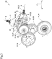
- eine perspektivische Darstellung einer erfindungsgemäßen Getriebeeinheit einschließlich eines Getriebegehäuses;
- Fig. 3
- eine perspektivische Darstellung der Getriebeeinheit aus
Fig.2 ohne das Getriebegehäuse; - Fig. 4
- eine Vorderansicht der Getriebeeinheit aus
Fig.2 ohne das Getriebegehäuse in einem ersten Zustand; - Fig. 5
- eine Vorderansicht der Getriebeeinheit aus
Fig.2 ohne das Getriebegehäuse in einem zweiten Zustand; und - Fig. 6
- eine Schnittdarstellung eines Teils der Getriebeeinheit aus
Fig.2 . -
Fig. 1 zeigt eine Rundballenpresse 1 gemäß der vorliegenden Erfindung, mit einer erfindungsgemäßen Getriebeeinheit 20. In den Figuren sind eine Längsachse X, eine Querachse Y sowie eine Hochachse Z der Rundballenpresse 1 eingezeichnet. Die Rundballenpresse 1 ist dazu vorgesehen, von einer Zugmaschine beziehungsweise einem Schlepper (nicht dargestellt) gezogen zu werden. An einem Rahmen 2 der Rundballenpresse 1 ist abgesehen von Laufrädern 3, auf welchen die Rundballenpresse 1 aufsteht, eine Pressvorrichtung 10 angeordnet, die eine Presskammer 8 variabler Größe zur Bildung eines Erntegutballens 60 ausbilden kann. Mit einer in Fahrtrichtung R vorderseitig am Rahmen 2 angeordneten Pick-up 4 wird das Erntegut wie zum Beispiel Stroh, Heu oder Gras, vom Boden aufgenommen und gelangt weiter zu einem Schneidrotor 5, der als Zuführelement fungiert. Er ergreift das Erntegut, zerschneidet es und transportiert es weiter entgegen der Fahrtrichtung R und durch einen Förderkanal 6 in Richtung eines Zuführbereichs 7 der Presskammer 8. Statt des Schneidrotors 5 kann auch ein einfacher Förderrotor vorgesehen sein. - Die Pressvorrichtung 10 weist in diesem Fall eine Presswalze 11 auf, welche als erstes Presselement dient, eine dieser gegenüberliegende Starterwalze 12, sowie einen als zweites Presselement fungierenden Pressriemen 13, welche zusammen die Presskammer 8 definieren. Die Presswalze 11 sowie der Pressriemen 12 bewirken eine Rotation des Erntegutballens 50 und gleichzeitig ein Verpressen des Ernteguts. Der Pressriemen 13 ist über eine Mehrzahl drehbar gelagerten Führungsrollen 14 sowie Antriebsrollen 15 geführt und wird durch diese unter Spannung gehalten. Während die Führungsrollen 14 rein passiv gegenüber dem Rahmen drehbar sind, sind die Antriebsrollen 15 aktiv antreibbar und dienen dazu, den Pressriemen 13 in eine umlaufende Bewegung zu versetzen.
- Die dargestellte Rundballenpresse 1 verfügt über keinen eigenen Antriebsmotor. Sämtliche Antriebsleistung wird vom Schlepper übertragen. In diesem Fall wird die Pick-up 4 hydraulisch angetrieben, wozu die Rundballenpresse 1 mit einer nicht dargestellten Hydraulikleitung mit dem Schlepper verbunden wird. Die Antriebsleistung für den Schneidrotor 5, die Presswalze 11, die Starterwalze 12 sowie den Pressriemen 13 wird hingegen mechanisch seitens des Schleppers übertragen. Hierzu wird eine in
Fig.1 schematisch dargestellte Eingangswelle 16, die als Gelenkwelle ausgebildet ist, mit einer Zapfwelle des Schleppers verbunden. Die Eingangswelle 16 führt zu der inFig.1 nur angedeuteten und inFig.2 bis 6 im Detail dargestellten Getriebeeinheit 20. Ein drehfest mit der Eingangswelle 16 verbundenes Eingangswellen-Zahnrad 17 kämmt mit einem Antriebswellen-Zahnrad 28, das seinerseits drehfest mit einer Antriebswelle 23 verbunden ist. Die genannten Zahnräder 17, 28 sind als Kegelräder ausgebildet. Die Antriebswelle 23 bildet ein zentrales Element eines Antriebsteils 22 der Getriebeeinheit 20. Auch die Eingangswelle 16, das Eingangswellen-Zahnrad 17 und das Antriebswellen-Zahnrad 28 können als Elemente des Antriebsteils 22 angesehen werden. Die Eingangswelle 16 ist über zwei (inFig.6 dargestellte) Wälzlager 27 um eine Antriebswellen-Drehachse A, die hier parallel zur Querachse Y verläuft, drehbar am Getriebegehäuse 21 gelagert. Die Eingangswelle 16 ist um eine zur Antriebswellen-Drehachse A senkrecht verlaufende Eingangswellen-Drehachse B drehbar. Während das Antriebswellen-Zahnrad 28 starr mit der Antriebswelle 23 verbunden ist, sind zwei Kopplungszahnräder 30, 32 beweglich auf der Antriebswelle 23 angeordnet. Während das Antriebswellen-Zahnrad 28 in einem Lagerabschnitt 25 der Antriebswelle 23 zwischen den Wälzlagern 27 angeordnet ist, sind die Kopplungszahnräder 30, 32 in einem freitragenden Abschnitt 26 angeordnet. - Ein erstes Kopplungszahnrad 30, welches als Stirnrad ausgebildet ist, ist drehfest mit der Antriebswelle 23 verbunden, jedoch bezüglich der Antriebswelle-Drehachse A axial verschiebbar. Ein zweites Kopplungszahnrad 32, das näher am Lagerabschnitt 25 angeordnet ist, ist axial auf der Antriebswelle 23 fixiert, allerdings gegenüber dieser frei drehbar. Das erste Kopplungszahnrad 30 kämmt mit einem Presswalzen-Zahnrad 38, das drehfest mit der Presswalze 11 verbunden ist. Das Presswalzen-Zahnrad 38 gehört zu einem Presswalzen-Abtriebsteil 37 der Getriebeeinheit 20, welcher auch als erstes Presselement-Abtriebsteil bezeichnet werden kann. Die Presswalze 11 ist durch einen nicht dargestellten Kettenantrieb an die Starterwalze 12 gekoppelt. Das zweite Kopplungszahnrad 32 kämmt mit einem Zwischenzahnrad 35, das seinerseits wiederum mit einem Schneidrotor-Zahnrad 36 kämmt, welches drehfest mit dem Schneidrotor 5 verbunden ist. Das zweite Kopplungszahnrad 32, das Zwischenzahnrad 35 sowie das Schneidrotor-Zahnrad 36 gehören zu einem Schneidrotor-Abtriebsteil 34, welcher auch als Zuführelement-Abtriebswelle bezeichnet werden kann. Die hier genannten Zahnräder 30, 32, 35, 36, 38 sind alle als Stirnräder ausgebildet.
- Das Antriebswellen-Zahnrad 28 kämmt mit einem ebenfalls als Kegelrad ausgebildeten Verbindungswellen-Zahnrad 40, das auf einer aufwärts verlaufenden Verbindungswelle 41 sitzt. Diese ist um eine senkrecht zur Antriebswellen-Drehachse A verlaufende Verbindungswellen-Drehachse E drehbar und stellt eine Verbindung zu einem Antriebsrollengetriebe 42 her, über welches die Antriebsrollen 15 antreibbar sind. Das Verbindungswellen-Zahnrad 40 gehört zu einem Pressriemen-Abtriebsteil 39 der Getriebeeinheit 20, welcher auch als zweiter Presselement-Abtriebsteil bezeichnet werden kann.
- Während der Antriebsteil 22 permanent antreibend mit dem Presswalzen-Abtriebsteil 37 und dem Pressriemen-Abtriebsteil 39 gekoppelt ist, ist die Kopplung zwischen Antriebsteil 22 und Schneidrotor-Abtriebsteil 34 von der Stellung des ersten Kopplungszahnrad 30 abhängig. Im normalen Betriebszustand der Rundballenpresse 1 ist das erste Kopplungszahnrad 30 in einer Kopplungsstellung angeordnet, in welcher es über eine Klauenkupplung 33 mit dem zweiten Kopplungszahnrad 32 eingreift. Durch den Formschluss der Klauenkupplung 33 wird das zweite Kopplungszahnrad 32 drehfest mit dem ersten Kopplungszahnrad 30 und somit auch mit der Antriebswelle 23 verbunden. Entsprechend sind die Bewegung der Presswalze 11, des Pressriemens 13 sowie des Schneidrotors 5 über die Getriebeeinheit 20 aneinander gekoppelt.
- Im Fall einer Blockade des Schneidrotors 5, zum Beispiel aufgrund eines Erntegutstaus oder eines mit aufgenommenen Fremdkörpers, ist es sinnvoll, den Antrieb der Rundballenpresse 1 zu stoppen und den Schneidrotor 5 händisch entgegen seiner normalen Drehrichtung zu bewegen, um die Blockade beheben zu können. Um zu vermeiden, dass auch der Pressriemen 13 sowie die Presswalze 11 mit bewegt werden müssen, wird hierzu der Schneidrotor-Abtriebsteil 34 vom Antriebsteil 22 entkoppelt. Dabei wird das erste Kopplungszahnrad 30 axial vom zweiten Kopplungszahnrad 32 fort in eine Freigabestellung verschoben, so dass der Formschluss über die Klauenkupplung 33 aufgehoben wird. Danach sind das zweite Kopplungszahnrad 32 und die Antriebswelle 23 frei gegeneinander drehbar. Das Presswalzen-Zahnrad 38 ist so breit ausgelegt, dass das erste Kopplungszahnrad 30 während der gesamten Verschiebung und auch beim Erreichen der Freigabestellung mit dem Presswalzen-Zahnrad 38 in Eingriff bleibt.
- Sofern keine weiteren Axialkräfte auf das erste Kopplungszahnrad 30 einwirken, wird es durch ein Kopplungs-Federelement 31, das als Schraubenfeder die Antriebswelle 23 umgibt, in die Kopplungsstellung geschoben beziehungsweise in dieser gehalten. Um das erste Kopplungszahnrad 30 in die Freigabestellung zu verschieben, kann ein Benutzer einen Schaltmechanismus 43 nutzen. Dieser weist zum einen eine als Schaltelement dienende Schaltgabel 44 auf sowie zum anderen ein Stellelement 48. Die Schaltgabel 44 ist gegenüber dem Getriebegehäuse 21 um eine senkrecht zur Antriebswellen-Drehachse A verlaufende Schaltgabel-Schwenkachse F schwenkbar, während das Stellelement um eine ebenfalls zur Antriebswellen-Drehachse A senkrechte Stellelement-Schwenkachse G schwenkbar ist. Die Schaltgabel 44 weist zwei Schaltabschnitte 45 auf, mit welchen sie axial seitlich am ersten Kopplungszahnrad 30 angreifen kann, um dieses in die Freigabestellung zu verschieben. Um die Reibung zu reduzieren, weist jeder Schaltabschnitt 45 ein Kugellager (ohne Bezugszeichen) auf. Bezüglich der Schaltgabel-Schwenkachse F den Schaltabschnitten 45 gegenüberliegend ist ein Stellabschnitt 46 ausgebildet. Das Stellelement 48 weist einen Exzenterabschnitt 49 auf, der mit dem Stellabschnitt 46 zusammenwirken kann, um die Schaltgabel 44 aus einer in
Fig. 4 dargestellten Passivstellung in eine inFig. 5 dargestellte Aktivstellung zu verstellen. Beim Verstellen, das heißt Schwenken, der Schaltgabel 44 aus der Passivstellung in die Aktivstellung wirken die Schaltabschnitte 45 axial seitlich auf das erste Kopplungszahnrad 30 ein und drücken dieses entgegen der Kraft des Kopplungs-Federelements 31 in die Freigabestellung. - Ohne die Einwirkung des Stellelements 48 wird die Schaltgabel 44 durch ein Schalt-Federelement 47, das in hier nicht näher dargestellter Weise mit dem Getriebegehäuse 21 verbunden ist, in der Passivstellung gehalten. Wird allerdings das Stellelement 48 gedreht, übt der Exzenterabschnitt 49 eine Kraft auf den Stellabschnitt 46 und somit ein Drehmoment auf die Schaltgabel 44 aus. Form und Position von Exzenterabschnitt 49 und Stellabschnitt 46 sind so aufeinander abgestimmt, dass ausgehend von der Passivstellung der Schaltgabel 44 der Stellabschnitt 46 zunächst vergleichsweise nah an der Stellelement-Schwenkachse G mit dem Exzenterabschnitt 49 zusammenwirkt. Dementsprechend resultiert aus einem gegebenen Drehmoment im Stellelement 48 zunächst eine relativ große Kraft auf den Stellabschnitt 46 und somit auch eine relativ große Kraft auf das erste Kopplungszahnrad 30. Dies dient dazu, eine anfängliche Haftreibung zwischen ersten Kopplungszahnrad 30 und Antriebswelle 23 zu überwinden. Im weiteren Verlauf der Drehung des Stellelements 48 verschiebt sich der Kontaktpunkt zum Stellabschnitt 46 von der Stellelement-Schwenkachse G fort, so dass eine geringere Kraft resultiert, allerdings einen größerer Verschiebungsweg erreicht werden kann. Das Stellelement 48 weist ein Antriebsprofil 50 auf, in diesem Fall ein Außensechskant-Profil, das von außerhalb des Getriebegehäuses 21 zugänglich ist. Der Benutzer kann mit einem geeigneten Schraubenschlüssel auf das Antriebsprofil 50 einwirken und hierdurch die Verstellung des Stellelements 48 bewirken, aus welcher die Verstellung der Schaltgabel 44 in die aktive Stellung und die Verstellung des ersten Kopplungszahnrads 30 in die Freigabestellung resultieren. Wenn der Benutzer das Stellelement wieder zurückstellt, kehren die Schaltgabel 44 und das erste Kopplungszahnrad 30 aufgrund der Vorspannung durch die Federelemente 31, 47 in die Passivstellung sowie in die Kopplungsstellung zurück.
Claims (15)
- Getriebeeinheit (20) für eine Rundballenpresse (1), mit einem zum Einkoppeln eines Antriebsdrehmoments ausgebildeten Antriebsteil (22), aufweisend eine um eine Antriebswellen-Drehachse (A) drehbare Antriebswelle (23), einem Presselement-Abtriebsteil (37), an welchen der Antriebsteil (22) antreibend gekoppelt ist und welcher dazu vorgesehen ist, wenigstens indirekt ein Presselement (11) anzutreiben, um auf Erntegut in einer Presskammer (8) einzuwirken, einem Zuführelement-Abtriebsteil (34), welcher dazu vorgesehen ist, wenigstens indirekt ein Zuführelement (5) anzutreiben, um Erntegut zur Presskammer (8) hin zu fördern, sowie einem Kopplungsmechanismus (29) zum wahlweisen Koppeln und Entkoppeln von Antriebsteil (22) und Zuführelement-Abtriebsteil (34),
dadurch gekennzeichnet, dass
der Kopplungsmechanismus (29) ein erstes Kopplungszahnrad (30) aufweist, das verdrehsicher mit der Antriebswelle (23) verbunden und axial gegenüber dieser verstellbar ist, wodurch es wahlweise in einer Kopplungsstellung mit dem Zuführelement-Abtriebsteil (34) antreibend koppelbar und in einer Freigabestellung von diesem entkoppelbar ist, wobei das erste Kopplungszahnrad (30) sowohl in der Kopplungsstellung als auch in der Freigabestellung antreibend mit dem Presselement-Abtriebsteil (37) gekoppelt ist. - Getriebeeinheit nach Anspruch 1, dadurch gekennzeichnet, dass der Zuführelement-Abtriebsteil (34) ein zweites Kopplungszahnrad (32) aufweist, das die Antriebswelle (23) koaxial umgibt, wobei das erste Kopplungszahnrad (30) in der Kopplungsstellung durch einen Formschluss mit dem zweiten Kopplungszahnrad (32) dieses verdrehsicher mit der Antriebswelle (23) verbindet, während das zweite Kopplungszahnrad (32) durch Aufheben des Formschlusses in der Freigabestellung frei gegenüber der Antriebswelle (23) drehbar ist.
- Getriebeeinheit nach einem der vorangehenden Ansprüche, dadurch gekennzeichnet, dass diese ein Getriebegehäuse (21) zur stationären Anordnung an der Rundballenpresse (1) aufweist und die Antriebswelle (23) einen am Getriebegehäuse (21) drehbar gelagerten Lagerabschnitt (25) aufweist sowie einen freitragenden Abschnitt (26), wobei die Kopplungszahnräder (30, 32) am freitragenden Abschnitt (26) angeordnet sind.
- Getriebeeinheit nach einem der vorangehenden Ansprüche, dadurch gekennzeichnet, dass das erste Kopplungszahnrad (30) antreibend mit einem ersten Presselement-Abtriebsteil (37) gekoppelt ist und ein verdrehsicher mit der Antriebswelle (23) verbundenes Antriebswellen-Zahnrad (28) antreibend mit einem zweiten Presselement-Abtriebsteil (39) gekoppelt ist.
- Getriebeeinheit nach einem der vorangehenden Ansprüche, dadurch gekennzeichnet, dass der erste Presselement-Abtriebsteil (37) dazu vorgesehen ist, wenigstens indirekt eine Presswalze (11) in einem Zuführbereich (7) der Presskammer (8) anzutreiben, und der zweite Presselement-Abtriebsteil (39) dazu vorgesehen ist, wenigstens indirekt ein endloses, umlaufend antreibbares Presselement (13) anzutreiben.
- Getriebeeinheit nach einem der vorangehenden Ansprüche, dadurch gekennzeichnet, dass der erste Presselement-Abtriebsteil (37) ein Presswalzen-Zahnrad (38) aufweist, das zur verdrehsicheren Verbindung mit einer Presswalze (11) vorgesehen ist und das, entweder direkt oder indirekt über wenigstens ein Zwischenzahnrad, mit dem ersten Kopplungszahnrad (30) zusammenwirkt.
- Getriebeeinheit nach einem der vorangehenden Ansprüche, dadurch gekennzeichnet, dass der Förderelement-Abtriebsteil (34) ein Förderelement-Zahnrad (36) aufweist, das zur verdrehsicheren Verbindung mit dem Förderelement (5) vorgesehen ist und das, entweder direkt oder indirekt über wenigstens ein Zwischenzahnrad (35), mit dem zweiten Kopplungszahnrad (32) zusammenwirkt.
- Getriebeeinheit nach einem der vorangehenden Ansprüche, dadurch gekennzeichnet, dass das Antriebswellen-Zahnrad (28) mit einem Eingangswellen-Zahnrad (17) zusammenwirkt, durch welches das Antriebsdrehmoment auf die Antriebswelle (23) übertragbar ist.
- Getriebeeinheit nach einem der vorangehenden Ansprüche, dadurch gekennzeichnet, dass das erste Kopplungszahnrad (30) durch ein Kopplungs-Federelement (31) in Richtung auf die Kopplungsstellung vorgespannt ist.
- Getriebeeinheit nach einem der vorangehenden Ansprüche, dadurch gekennzeichnet, dass diese einen Schaltmechanismus (43) aufweist, mit wenigstens einem Schaltelement (44), das zwischen einer Passivstellung und einer Aktivstellung verstellbar ist und beim Verstellen in die Aktivstellung axial seitlich am ersten Kopplungszahnrad (30) angreift und dieses die Freigabestellung verstellt.
- Getriebeeinheit nach einem der vorangehenden Ansprüche, dadurch gekennzeichnet, dass das Schaltelement (44) durch Schwenken um eine Schaltelement-Schwenkachse (F) zwischen der Aktivstellung und der Passivstellung verstellbar ist und mit wenigstens einem von der Schaltelement-Schwenkachse (F) beabstandeten Schaltabschnitt (45) am ersten Kopplungszahnrad (30) angreift.
- Getriebeeinheit nach einem der vorangehenden Ansprüche, dadurch gekennzeichnet, dass der Schaltmechanismus (43) ein Stellelement (48) aufweist, das dazu eingerichtet ist, das Schaltelement (44) zu beaufschlagen, um dieses in die Aktivstellung zu verstellen.
- Getriebeeinheit nach einem der vorangehenden Ansprüche, dadurch gekennzeichnet, dass das Stelleelement (48) um eine Stellelement-Schwenkachse (G) schwenkbar ist und einen Exzenterabschnitt (49) aufweist, der mit einem Stellabschnitt (46) des Schaltelements (44) zusammenwirkt, welcher von der Schaltelement-Schwenkachse (F) sowie von dem wenigstens einen Schaltabschnitt (45) beabstandet ist.
- Getriebeeinheit nach einem der vorangehenden Ansprüche, dadurch gekennzeichnet, dass das Stellelement (48) ein außerhalb eines Getriebegehäuses (21) angeordnetes Antriebsprofil (50) zum formschlüssigen Eingriff mit einem Werkzeug aufweist.
- Rundballenpresse (1) mit einem Rahmen (2), einem relativ zum Rahmen (2) antreibbaren Presselement (11), welches dazu ausgebildet ist, auf Erntegut in einer Presskammer (8) einzuwirken, einem relativ zum Rahmen (2) antreibbaren Zuführelement (5), welches dazu ausgebildet ist, Erntegut zur Presskammer (8) hin zu fördern, sowie mit einer Getriebeeinheit (20) nach einem der vorangehenden Ansprüche, wobei der Presselement-Abtriebsteil (37) wenigstens indirekt antreibend an das Presselement (11) gekoppelt ist und der Zuführelement-Abtriebsteil (34) wenigstens indirekt antreibend an das Zuführelement (5) gekoppelt ist.
Applications Claiming Priority (1)
| Application Number | Priority Date | Filing Date | Title |
|---|---|---|---|
| DE102023113954.1A DE102023113954A1 (de) | 2023-05-26 | 2023-05-26 | Getriebeeinheit |
Publications (2)
| Publication Number | Publication Date |
|---|---|
| EP4466976A1 true EP4466976A1 (de) | 2024-11-27 |
| EP4466976B1 EP4466976B1 (de) | 2025-09-10 |
Family
ID=90730450
Family Applications (1)
| Application Number | Title | Priority Date | Filing Date |
|---|---|---|---|
| EP24169939.6A Active EP4466976B1 (de) | 2023-05-26 | 2024-04-12 | Getriebeeinheit |
Country Status (4)
| Country | Link |
|---|---|
| US (1) | US20240407301A1 (de) |
| EP (1) | EP4466976B1 (de) |
| DE (1) | DE102023113954A1 (de) |
| PL (1) | PL4466976T3 (de) |
Citations (7)
| Publication number | Priority date | Publication date | Assignee | Title |
|---|---|---|---|---|
| EP0970599B1 (de) * | 1998-07-09 | 2002-09-25 | Kverneland Geldrop B.V. | Rundballenpresse |
| US7181899B2 (en) * | 2004-05-11 | 2007-02-27 | Maschinenfabrik Bernard Krone Gmbh | Machine for collecting and pressing an agricultural harvest |
| EP2556744A1 (de) * | 2011-08-10 | 2013-02-13 | Maschinenfabrik Bernard Krone GmbH | Landwirtschaftliche Rundballenpresse |
| US20220330487A1 (en) * | 2021-04-16 | 2022-10-20 | Maschinenfabrik Bernard Krone GmbH & Co. KG | Round Baler with Starter Roll and Elastically Deflectable Deflector Element |
| US20220408654A1 (en) * | 2021-06-23 | 2022-12-29 | Maschinenfabrik Bernard Krone GmbH & Co. KG | Round Baler |
| EP4176705A1 (de) * | 2021-11-08 | 2023-05-10 | Maschinenfabrik Bernard Krone GmbH & Co. KG | Rundballenpresse mit einer vorrichtung zum klemmen eines ballens |
| EP4183244A1 (de) * | 2021-11-19 | 2023-05-24 | Maschinenfabrik Bernard Krone GmbH & Co. KG | Rundballenpresse |
-
2023
- 2023-05-26 DE DE102023113954.1A patent/DE102023113954A1/de active Pending
-
2024
- 2024-04-12 EP EP24169939.6A patent/EP4466976B1/de active Active
- 2024-04-12 PL PL24169939.6T patent/PL4466976T3/pl unknown
- 2024-05-24 US US18/673,369 patent/US20240407301A1/en active Pending
Patent Citations (7)
| Publication number | Priority date | Publication date | Assignee | Title |
|---|---|---|---|---|
| EP0970599B1 (de) * | 1998-07-09 | 2002-09-25 | Kverneland Geldrop B.V. | Rundballenpresse |
| US7181899B2 (en) * | 2004-05-11 | 2007-02-27 | Maschinenfabrik Bernard Krone Gmbh | Machine for collecting and pressing an agricultural harvest |
| EP2556744A1 (de) * | 2011-08-10 | 2013-02-13 | Maschinenfabrik Bernard Krone GmbH | Landwirtschaftliche Rundballenpresse |
| US20220330487A1 (en) * | 2021-04-16 | 2022-10-20 | Maschinenfabrik Bernard Krone GmbH & Co. KG | Round Baler with Starter Roll and Elastically Deflectable Deflector Element |
| US20220408654A1 (en) * | 2021-06-23 | 2022-12-29 | Maschinenfabrik Bernard Krone GmbH & Co. KG | Round Baler |
| EP4176705A1 (de) * | 2021-11-08 | 2023-05-10 | Maschinenfabrik Bernard Krone GmbH & Co. KG | Rundballenpresse mit einer vorrichtung zum klemmen eines ballens |
| EP4183244A1 (de) * | 2021-11-19 | 2023-05-24 | Maschinenfabrik Bernard Krone GmbH & Co. KG | Rundballenpresse |
Also Published As
| Publication number | Publication date |
|---|---|
| EP4466976B1 (de) | 2025-09-10 |
| DE102023113954A1 (de) | 2024-11-28 |
| PL4466976T3 (pl) | 2025-11-12 |
| US20240407301A1 (en) | 2024-12-12 |
Similar Documents
| Publication | Publication Date | Title |
|---|---|---|
| DE69707050T2 (de) | Ernteaufsammeleinrichtung | |
| DE69323738T2 (de) | Ballenpresszuführmechanismus | |
| EP4151077B1 (de) | Getriebeanordnung zum antreiben eines presskolbens einer quaderballenpresse | |
| EP4108069B1 (de) | Rundballenpresse | |
| DE29702902U1 (de) | Maschine zum reihenunabhängigen Mähen von Mais u.dgl. stengelartigem Erntegut | |
| EP4385311B1 (de) | Getriebeanordnung für eine quaderballenpresse | |
| DE68907517T2 (de) | Ballenpresse. | |
| EP0499064B1 (de) | Maschine zum Aufnehmen und Pressen von landwirtschaftlichem Erntegut | |
| EP2995192B1 (de) | Quaderballenpresse | |
| EP4466976B1 (de) | Getriebeeinheit | |
| EP3732953B1 (de) | Schneidvorrichtung | |
| EP4056026A1 (de) | Fördervorrichtung für eine ballenpresse | |
| EP1738634B1 (de) | Erntegutaufnahmeeinrichtung und Erntemaschine | |
| DE102019006252B4 (de) | Antriebsanordnung für eine Rundballenpresse und Rundballenpresse mit der Antriebsanordnung | |
| DE4232989A1 (de) | Aufsammelkolbenpresse für landwirtschaftliches Erntegut | |
| DE102005062266B4 (de) | Förderer | |
| EP4039080B1 (de) | Ballenpresse | |
| EP4282250B1 (de) | Rundballenpresse | |
| DE102022115799A1 (de) | Einzugsanordnung für eine landmaschine | |
| EP0212186A1 (de) | Ladewagen | |
| DE102025119441A1 (de) | Landwirtschaftliche ballenpresse | |
| EP4442109A1 (de) | Bindeeinheit für eine rundballenpresse | |
| DE102023103528A1 (de) | Bindevorrichtung für eine ballenpresse | |
| EP4442108A1 (de) | Rundballenpresse | |
| EP1595436A1 (de) | Erntenmaschine mit einer Aufnahmevorrichtung für landwirtschaftliches Erntegut |
Legal Events
| Date | Code | Title | Description |
|---|---|---|---|
| PUAI | Public reference made under article 153(3) epc to a published international application that has entered the european phase |
Free format text: ORIGINAL CODE: 0009012 |
|
| STAA | Information on the status of an ep patent application or granted ep patent |
Free format text: STATUS: THE APPLICATION HAS BEEN PUBLISHED |
|
| AK | Designated contracting states |
Kind code of ref document: A1 Designated state(s): AL AT BE BG CH CY CZ DE DK EE ES FI FR GB GR HR HU IE IS IT LI LT LU LV MC ME MK MT NL NO PL PT RO RS SE SI SK SM TR |
|
| STAA | Information on the status of an ep patent application or granted ep patent |
Free format text: STATUS: REQUEST FOR EXAMINATION WAS MADE |
|
| 17P | Request for examination filed |
Effective date: 20241213 |
|
| GRAP | Despatch of communication of intention to grant a patent |
Free format text: ORIGINAL CODE: EPIDOSNIGR1 |
|
| STAA | Information on the status of an ep patent application or granted ep patent |
Free format text: STATUS: GRANT OF PATENT IS INTENDED |
|
| RIC1 | Information provided on ipc code assigned before grant |
Ipc: A01F 15/18 20060101ALI20250422BHEP Ipc: A01F 15/10 20060101ALI20250422BHEP Ipc: A01F 15/08 20060101ALI20250422BHEP Ipc: A01F 15/07 20060101AFI20250422BHEP |
|
| INTG | Intention to grant announced |
Effective date: 20250519 |
|
| GRAS | Grant fee paid |
Free format text: ORIGINAL CODE: EPIDOSNIGR3 |
|
| GRAA | (expected) grant |
Free format text: ORIGINAL CODE: 0009210 |
|
| STAA | Information on the status of an ep patent application or granted ep patent |
Free format text: STATUS: THE PATENT HAS BEEN GRANTED |
|
| AK | Designated contracting states |
Kind code of ref document: B1 Designated state(s): AL AT BE BG CH CY CZ DE DK EE ES FI FR GB GR HR HU IE IS IT LI LT LU LV MC ME MK MT NL NO PL PT RO RS SE SI SK SM TR |
|
| REG | Reference to a national code |
Ref country code: GB Ref legal event code: FG4D Free format text: NOT ENGLISH |
|
| REG | Reference to a national code |
Ref country code: CH Ref legal event code: EP |
|
| REG | Reference to a national code |
Ref country code: DE Ref legal event code: R096 Ref document number: 502024000218 Country of ref document: DE |
|
| REG | Reference to a national code |
Ref country code: IE Ref legal event code: FG4D Free format text: LANGUAGE OF EP DOCUMENT: GERMAN |
|
| P01 | Opt-out of the competence of the unified patent court (upc) registered |
Free format text: CASE NUMBER: UPC_APP_7182_4466976/2025 Effective date: 20250916 |
|
| REG | Reference to a national code |
Ref country code: NL Ref legal event code: FP |
|
| PG25 | Lapsed in a contracting state [announced via postgrant information from national office to epo] |
Ref country code: NO Free format text: LAPSE BECAUSE OF FAILURE TO SUBMIT A TRANSLATION OF THE DESCRIPTION OR TO PAY THE FEE WITHIN THE PRESCRIBED TIME-LIMIT Effective date: 20251210 |
|
| REG | Reference to a national code |
Ref country code: LT Ref legal event code: MG9D |
|
| PG25 | Lapsed in a contracting state [announced via postgrant information from national office to epo] |
Ref country code: FI Free format text: LAPSE BECAUSE OF FAILURE TO SUBMIT A TRANSLATION OF THE DESCRIPTION OR TO PAY THE FEE WITHIN THE PRESCRIBED TIME-LIMIT Effective date: 20250910 |
|
| PG25 | Lapsed in a contracting state [announced via postgrant information from national office to epo] |
Ref country code: HR Free format text: LAPSE BECAUSE OF FAILURE TO SUBMIT A TRANSLATION OF THE DESCRIPTION OR TO PAY THE FEE WITHIN THE PRESCRIBED TIME-LIMIT Effective date: 20250910 |
|
| PG25 | Lapsed in a contracting state [announced via postgrant information from national office to epo] |
Ref country code: GR Free format text: LAPSE BECAUSE OF FAILURE TO SUBMIT A TRANSLATION OF THE DESCRIPTION OR TO PAY THE FEE WITHIN THE PRESCRIBED TIME-LIMIT Effective date: 20251211 |
|
| PG25 | Lapsed in a contracting state [announced via postgrant information from national office to epo] |
Ref country code: SE Free format text: LAPSE BECAUSE OF FAILURE TO SUBMIT A TRANSLATION OF THE DESCRIPTION OR TO PAY THE FEE WITHIN THE PRESCRIBED TIME-LIMIT Effective date: 20250910 |
|
| PG25 | Lapsed in a contracting state [announced via postgrant information from national office to epo] |
Ref country code: LV Free format text: LAPSE BECAUSE OF FAILURE TO SUBMIT A TRANSLATION OF THE DESCRIPTION OR TO PAY THE FEE WITHIN THE PRESCRIBED TIME-LIMIT Effective date: 20250910 |
|
| PG25 | Lapsed in a contracting state [announced via postgrant information from national office to epo] |
Ref country code: BG Free format text: LAPSE BECAUSE OF FAILURE TO SUBMIT A TRANSLATION OF THE DESCRIPTION OR TO PAY THE FEE WITHIN THE PRESCRIBED TIME-LIMIT Effective date: 20250910 |
|
| PG25 | Lapsed in a contracting state [announced via postgrant information from national office to epo] |
Ref country code: RS Free format text: LAPSE BECAUSE OF FAILURE TO SUBMIT A TRANSLATION OF THE DESCRIPTION OR TO PAY THE FEE WITHIN THE PRESCRIBED TIME-LIMIT Effective date: 20251210 |
|
| PG25 | Lapsed in a contracting state [announced via postgrant information from national office to epo] |
Ref country code: ES Free format text: LAPSE BECAUSE OF FAILURE TO SUBMIT A TRANSLATION OF THE DESCRIPTION OR TO PAY THE FEE WITHIN THE PRESCRIBED TIME-LIMIT Effective date: 20250910 |
|
| PG25 | Lapsed in a contracting state [announced via postgrant information from national office to epo] |
Ref country code: SM Free format text: LAPSE BECAUSE OF FAILURE TO SUBMIT A TRANSLATION OF THE DESCRIPTION OR TO PAY THE FEE WITHIN THE PRESCRIBED TIME-LIMIT Effective date: 20250910 |
|
| PG25 | Lapsed in a contracting state [announced via postgrant information from national office to epo] |
Ref country code: IS Free format text: LAPSE BECAUSE OF FAILURE TO SUBMIT A TRANSLATION OF THE DESCRIPTION OR TO PAY THE FEE WITHIN THE PRESCRIBED TIME-LIMIT Effective date: 20260110 |
|
| PG25 | Lapsed in a contracting state [announced via postgrant information from national office to epo] |
Ref country code: CZ Free format text: LAPSE BECAUSE OF FAILURE TO SUBMIT A TRANSLATION OF THE DESCRIPTION OR TO PAY THE FEE WITHIN THE PRESCRIBED TIME-LIMIT Effective date: 20250910 Ref country code: PT Free format text: LAPSE BECAUSE OF FAILURE TO SUBMIT A TRANSLATION OF THE DESCRIPTION OR TO PAY THE FEE WITHIN THE PRESCRIBED TIME-LIMIT Effective date: 20260112 |
|
| PGFP | Annual fee paid to national office [announced via postgrant information from national office to epo] |
Ref country code: PL Payment date: 20260330 Year of fee payment: 3 |
|
| PG25 | Lapsed in a contracting state [announced via postgrant information from national office to epo] |
Ref country code: EE Free format text: LAPSE BECAUSE OF FAILURE TO SUBMIT A TRANSLATION OF THE DESCRIPTION OR TO PAY THE FEE WITHIN THE PRESCRIBED TIME-LIMIT Effective date: 20250910 Ref country code: SK Free format text: LAPSE BECAUSE OF FAILURE TO SUBMIT A TRANSLATION OF THE DESCRIPTION OR TO PAY THE FEE WITHIN THE PRESCRIBED TIME-LIMIT Effective date: 20250910 |
|
| REG | Reference to a national code |
Ref country code: DE Ref legal event code: R097 Ref document number: 502024000218 Country of ref document: DE |
|
| PG25 | Lapsed in a contracting state [announced via postgrant information from national office to epo] |
Ref country code: LT Free format text: LAPSE BECAUSE OF FAILURE TO SUBMIT A TRANSLATION OF THE DESCRIPTION OR TO PAY THE FEE WITHIN THE PRESCRIBED TIME-LIMIT Effective date: 20250910 |
|
| PG25 | Lapsed in a contracting state [announced via postgrant information from national office to epo] |
Ref country code: DK Free format text: LAPSE BECAUSE OF FAILURE TO SUBMIT A TRANSLATION OF THE DESCRIPTION OR TO PAY THE FEE WITHIN THE PRESCRIBED TIME-LIMIT Effective date: 20250910 |
|
| PGFP | Annual fee paid to national office [announced via postgrant information from national office to epo] |
Ref country code: IT Payment date: 20260430 Year of fee payment: 3 |
|
| PGFP | Annual fee paid to national office [announced via postgrant information from national office to epo] |
Ref country code: DE Payment date: 20260420 Year of fee payment: 3 |
|
| PGFP | Annual fee paid to national office [announced via postgrant information from national office to epo] |
Ref country code: AT Payment date: 20260714 Year of fee payment: 3 |
|
| PGFP | Annual fee paid to national office [announced via postgrant information from national office to epo] |
Ref country code: IE Payment date: 20260423 Year of fee payment: 3 Ref country code: BE Payment date: 20260422 Year of fee payment: 3 |
|
| PLBE | No opposition filed within time limit |
Free format text: ORIGINAL CODE: 0009261 |
|
| STAA | Information on the status of an ep patent application or granted ep patent |
Free format text: STATUS: NO OPPOSITION FILED WITHIN TIME LIMIT |
|
| REG | Reference to a national code |
Ref country code: CH Ref legal event code: L10 Free format text: ST27 STATUS EVENT CODE: U-0-0-L10-L00 (AS PROVIDED BY THE NATIONAL OFFICE) Effective date: 20260722 |
|
| PGFP | Annual fee paid to national office [announced via postgrant information from national office to epo] |
Ref country code: FR Payment date: 20260423 Year of fee payment: 3 |