EP4465768A1 - Tropfenerzeuger - Google Patents
Tropfenerzeuger Download PDFInfo
- Publication number
- EP4465768A1 EP4465768A1 EP23174083.8A EP23174083A EP4465768A1 EP 4465768 A1 EP4465768 A1 EP 4465768A1 EP 23174083 A EP23174083 A EP 23174083A EP 4465768 A1 EP4465768 A1 EP 4465768A1
- Authority
- EP
- European Patent Office
- Prior art keywords
- droplet generator
- target material
- piezo elements
- conduit
- molten target
- Prior art date
- Legal status (The legal status is an assumption and is not a legal conclusion. Google has not performed a legal analysis and makes no representation as to the accuracy of the status listed.)
- Withdrawn
Links
Images


Classifications
-
- B—PERFORMING OPERATIONS; TRANSPORTING
- B41—PRINTING; LINING MACHINES; TYPEWRITERS; STAMPS
- B41J—TYPEWRITERS; SELECTIVE PRINTING MECHANISMS, i.e. MECHANISMS PRINTING OTHERWISE THAN FROM A FORME; CORRECTION OF TYPOGRAPHICAL ERRORS
- B41J2/00—Typewriters or selective printing mechanisms characterised by the printing or marking process for which they are designed
- B41J2/005—Typewriters or selective printing mechanisms characterised by the printing or marking process for which they are designed characterised by bringing liquid or particles selectively into contact with a printing material
- B41J2/01—Ink jet
- B41J2/135—Nozzles
- B41J2/14—Structure thereof only for on-demand ink jet heads
- B41J2/14201—Structure of print heads with piezoelectric elements
- B41J2/1429—Structure of print heads with piezoelectric elements of tubular type
-
- H—ELECTRICITY
- H05—ELECTRIC TECHNIQUES NOT OTHERWISE PROVIDED FOR
- H05G—X-RAY TECHNIQUE
- H05G2/00—Apparatus or processes specially adapted for producing X-rays, not involving X-ray tubes, e.g. involving generation of a plasma
- H05G2/001—Production of X-ray radiation generated from plasma
- H05G2/002—Supply of the plasma generating material
- H05G2/0023—Constructional details of the ejection system
-
- H—ELECTRICITY
- H05—ELECTRIC TECHNIQUES NOT OTHERWISE PROVIDED FOR
- H05G—X-RAY TECHNIQUE
- H05G2/00—Apparatus or processes specially adapted for producing X-rays, not involving X-ray tubes, e.g. involving generation of a plasma
- H05G2/001—Production of X-ray radiation generated from plasma
- H05G2/003—Production of X-ray radiation generated from plasma the plasma being generated from a material in a liquid or gas state
- H05G2/0035—Production of X-ray radiation generated from plasma the plasma being generated from a material in a liquid or gas state the material containing metals as principal radiation-generating components
-
- H—ELECTRICITY
- H05—ELECTRIC TECHNIQUES NOT OTHERWISE PROVIDED FOR
- H05G—X-RAY TECHNIQUE
- H05G2/00—Apparatus or processes specially adapted for producing X-rays, not involving X-ray tubes, e.g. involving generation of a plasma
- H05G2/001—Production of X-ray radiation generated from plasma
- H05G2/008—Production of X-ray radiation generated from plasma involving an energy-carrying beam in the process of plasma generation
- H05G2/0082—Production of X-ray radiation generated from plasma involving an energy-carrying beam in the process of plasma generation the energy-carrying beam being a laser beam
Definitions
- the present disclosure relates to a droplet generator in particular, but not exclusively, for the generation of EUV light.
- the droplet generator can be used in connection with a lithographic apparatus, particularly, but not exclusively, an EUV lithography apparatus.
- the present disclosure also relates to an assembly for a lithography apparatus including such a droplet generator, and a lithography apparatus including such a droplet generator or assembly.
- the present disclosure relates to a method of generating a stream of molten target material droplets, as well as the use of such a droplet generator, assembly, lithography apparatus, or method in a lithography method or apparatus.
- a lithographic apparatus is a machine constructed to apply a desired pattern onto a substrate.
- a lithographic apparatus can be used, for example, in the manufacture of integrated circuits (ICs).
- a lithographic apparatus may, for example, project a pattern at a patterning device (e.g., a mask) onto a layer of radiation-sensitive material (resist) provided on a substrate.
- a patterning device e.g., a mask
- resist radiation-sensitive material
- a lithographic apparatus may use electromagnetic radiation.
- the wavelength of this radiation determines the minimum size of features which can be formed on the substrate.
- a lithographic apparatus which uses extreme ultraviolet (EUV) radiation, having a wavelength within the range 4-20 nm, for example 6.7 nm or 13.5 nm, may be used to form smaller features on a substrate than a lithographic apparatus which uses, for example, radiation with a wavelength of 193 nm.
- EUV extreme ultraviolet
- Methods for generating EUV light include, but are not limited to, altering the physical state of a source material, also known as a target material, to a plasma state.
- the source materials include a compound or an element, for example, xenon, lithium, or tin, with an emission line in the EUV range.
- LPP laser produced plasma
- the required plasma is produced by irradiating a source material, for example, in the form of a droplet, stream, or cluster of source material, with an amplified light beam that can be referred to as a drive laser.
- the plasma is typically produced in a sealed vessel, for example, a vacuum chamber. Where droplets are used, they are provided via a droplet generator apparatus, which is supplied with high pressure liquid source material.
- a droplet generator comprising: a conduit comprising an orifice configured to fluidly couple to a reservoir and to emit molten target material in a molten target material direction; a plurality of piezo elements at least partially surrounding the conduit, characterized in that at least one of the piezo elements is configured to operate in shear mode such that shear motion of the at least one piezo element is in the molten target material direction.
- Piezoelectric materials generate an internal strain resulting from an applied electric field and vice versa. As such, it is possible to control the deformation of a piezoelectric material by application of an electric field.
- Piezoelectric elements are used in inkjet printers for deforming a side wall of a chamber containing an ink to squeeze the ink out of an outlet. There are chambers adjacent to one another which share a common wall including a piezoelectric material such that when the wall is deformed in one direction, the associated chamber is squeezed and the adjacent chamber is refilled with ink. Such printers rely on changes in volume, and therefore pressure, to expel ink droplets. If the piezoelectric material is not activated by the application of an electric field, the ink will remain in the chambers.
- a radially poled piezo cylinder is provided around a capillary.
- the piezo cylinder is configured such that it excites molten target material flowing through the capillary in the acoustic frequency region via the so-called d33 and d31 modes of the piezo material. Such modes are in the thickness and length direction of the piezo cylinder. In such modes, the polarization and electric field are aligned.
- the flow is disrupted by the deformations of the piezoelectric material at least partially surrounding the capillary, causing it to split into droplets. Without deformation of the piezoelectric material, there would be a continuous stream of molten target material leaving the orifice.
- d15 mode also referred to as shear mode
- the electric field is perpendicular to polarization.
- This allows for a greater potential difference to be provided, which can be provided as either a positive or negative voltage, since the polarization is perpendicular to the applied field and is therefore less likely to be flipped by the application of an electric field.
- This allows an increase in sensitivity and therefore improved performance.
- the use of a shear mode in the same direction as the direction of the molten target material through the conduit results in the generation of droplets via perturbation of velocity rather than pressure, which also improves performance and reliability, particularly at higher frequencies.
- the plurality of piezo elements may at least partially or completely surround the conduit.
- the piezo elements may be distributed around the circumference of the conduit and be circumferentially spaced apart.
- the piezo elements are arranged to completely surround the conduit without being circumferentially spaced apart from one another.
- the plurality of piezo elements do not necessarily extend the full length of the conduit.
- the conduit may be a capillary.
- a capillary is sufficient to provide the molten target material.
- the conduit may be a glass capillary. Since the molten target material, such as tin, may be corrosive in its molten form to metals, it is preferable to use a material which is stable to exposure to the molten target material.
- the droplet generator may further include a controller configured to control voltage applied to the piezo elements.
- the controller may be configured to control the magnitude, frequency, and duty cycle of the voltage applied to the piezo elements in order to control the generation of droplets of the molten target material.
- At least one of the piezo elements includes segmented electrodes. These may be provided via application of a mask during deposition of the electrode or could be machined away after deposition. The use of segmented electrodes allows for improved performance since it is possible to individually control segments of the electrodes, thereby allowing for increased sensitivity.
- the segmented electrodes may be interdigitated. By interdigitating the electrodes, it is possible to alternate poling along the conduit. As such, in embodiments, the piezo elements are arranged such that poling is alternated along the conduit.
- At least one of the segmented electrodes may extend from an internal face of a piezo element to an external face of a piezo element. In this way, the number of connections required to control the piezo elements is reduced, thereby simplifying the apparatus.
- the droplet generator may include a pre-load tube at least partially surrounding the plurality of piezo elements. Since the piezo elements are configured to apply a force to the conduit, an equal and opposite force is provided by the conduit to the piezo elements. This could lead to the piezo elements moving away from the conduit rather than exerting the force on the conduit.
- the pre-load tube constrains the piezo elements such that they are not able to move away from the conduit and thereby apply more of the force generated to the conduit.
- the pre-load tube may partially or completely surround the plurality of piezo elements. Similarly, the pre-load tube may partially or completely extend along the axial length of the piezo elements.
- the droplet generator may be configured to provide a positive or negative potential difference to the plurality of piezo elements. Since the piezo elements are configured to shear in the direction of the molten target material, it is possible to provide a positive or a negative potential difference. In other modes, only a positive potential difference may be applied in order to avoid the problem of polarization being flipped.
- a gap may be provided between adjacent piezo elements.
- the gap is in the longitudinal axis of the conduit. Since the piezo elements are operated in shear mode in the same direction as the flow of molten target material, a gap may avoid adjacent piezo elements from applying a force to one another in operation.
- the molten target material may be a liquid metal.
- the metal is preferably tin or lithium.
- an assembly for a lithography apparatus including the droplet generator according to the first aspect of the present disclosure.
- the assembly may be a droplet generator apparatus for a lithography apparatus, preferably an EUV lithography apparatus.
- the assembly may include a molten target material reservoir, such as a molten tin reservoir.
- the assembly may include a means for moving molten target material from the molten target material reservoir.
- Such means may include a pump.
- Such means may include a pressure vessel configured to control the pressure of a gas therein to exert a pressure on molten target material within the vessel.
- the vessel may be the molten target material reservoir.
- the assembly may include valves configured to control the flow of molten target material through the assembly.
- Such valves may be freeze valves.
- a radiation source including a droplet generator according to the first aspect of the present disclosure or an assembly according to the second aspect of the present disclosure.
- the radiation source is preferably an EUV radiation source, although it will be appreciated that other radiation sources may utilize the droplet generator or assembly described herein.
- a lithography apparatus including the droplet generator according to the first aspect of the present disclosure, an assembly according to the second aspect of the present disclosure, or a radiation source according to the third aspect of the present disclosure.
- the lithography apparatus is an EUV lithography apparatus.
- a method of generating a stream of molten target material droplets including providing a conduit comprising an orifice configured to fluidly couple to a reservoir and to emit molten target material in a molten target material direction, said conduit being at least partially surrounded by a plurality of piezo elements, flowing a liquid target material through the conduit, and operating at least one of the plurality of piezo elements in shear mode such that shear motion of the piezo elements is in the molten target material direction to thereby generate a stream of molten target material droplets.
- the piezo elements by operating the piezo elements in shear mode such that the shear motion of the piezo elements is in the same direction as the molten target material direction, it is possible to perturb the velocity of the molten target material flowing through the conduit and cause it to separate into droplets. It is also possible to apply a larger potential difference before the polarization is flipped and so greater sensitivity can be provided.
- the method may include operating the plurality of piezo elements at a frequency of from around 20 kHz to around 20 MHz.
- a droplet generator according to a first aspect as assembly according to the second aspect, a radiation source according to the third aspect, a lithography apparatus according to the fourth aspect or a method according to the fifth aspect of the present disclosure in a lithography method or apparatus.
- the present invention will now be described with reference to an EUV lithography apparatus. However, it will be appreciated that the present invention is not limited to EUV lithography and may be suitable for other types of lithography.
- Figure 1 shows a lithographic system comprising a radiation source SO and a lithographic apparatus LA.
- the radiation source SO is configured to generate an EUV radiation beam B and to supply the EUV radiation beam B to the lithographic apparatus LA.
- the lithographic apparatus LA comprises an illumination system IL, a support structure MT configured to support a patterning device MA (e.g., a mask), a projection system PS and a substrate table WT configured to support a substrate W.
- a pellicle 15 may be provided to protect the patterning device MA from contamination.
- the illumination system IL is configured to condition the EUV radiation beam B before the EUV radiation beam B is incident upon the patterning device MA.
- the illumination system IL may include a facetted field mirror device 10 and a facetted pupil mirror device 11.
- the faceted field mirror device 10 and faceted pupil mirror device 11 together provide the EUV radiation beam B with a desired cross-sectional shape and a desired intensity distribution.
- the illumination system IL may include other mirrors or devices in addition to, or instead of, the faceted field mirror device 10 and faceted pupil mirror device 11.
- the EUV radiation beam B interacts with the patterning device MA. As a result of this interaction, a patterned EUV radiation beam B' is generated.
- the projection system PS is configured to project the patterned EUV radiation beam B' onto the substrate W.
- the projection system PS may comprise a plurality of mirrors 13,14 which are configured to project the patterned EUV radiation beam B' onto the substrate W held by the substrate table WT.
- the projection system PS may apply a reduction factor to the patterned EUV radiation beam B', thus forming an image with features that are smaller than corresponding features on the patterning device MA. For example, a reduction factor of 4 or 8 may be applied.
- the projection system PS is illustrated as having only two mirrors 13,14 in Figure 1 , the projection system PS may include a different number of mirrors (e.g., six or eight mirrors).
- the substrate W may include previously formed patterns. Where this is the case, the lithographic apparatus LA aligns the image, formed by the patterned EUV radiation beam B', with a pattern previously formed on the substrate W.
- a relative vacuum i.e. a small amount of gas (e.g. hydrogen) at a pressure well below atmospheric pressure, may be provided in the radiation source SO, in the illumination system IL, and/or in the projection system PS.
- gas e.g. hydrogen
- the radiation source SO shown in Figure 1 is, for example, of a type which may be referred to as a laser produced plasma (LPP) source.
- a laser system 1 which may, for example, include a CO 2 laser, is arranged to deposit energy via a laser beam 2 into a fuel, such as tin (Sn) which is provided from, e.g., a fuel emitter 3.
- Fuel emitter 3 may be connected to a droplet generator apparatus according to the present disclosure. Although tin is referred to in the following description, any suitable fuel may be used.
- the fuel is in liquid form, and may, for example, be a metal or alloy.
- the fuel emitter 3 may comprise a nozzle configured to direct tin, e.g.
- Collector 5 comprises, for example, a near-normal incidence radiation collector 5 (sometimes referred to more generally as a normal-incidence radiation collector).
- the collector 5 may have a multilayer mirror structure which is arranged to reflect EUV radiation (e.g., EUV radiation having a desired wavelength such as 13.5 nm).
- EUV radiation e.g., EUV radiation having a desired wavelength such as 13.5 nm.
- the collector 5 may have an ellipsoidal configuration, having two focal points. A first one of the focal points may be at the plasma formation region 4, and a second one of the focal points may be at an intermediate focus 6, as discussed below.
- the laser system 1 may be spatially separated from the radiation source SO. Where this is the case, the laser beam 2 may be passed from the laser system 1 to the radiation source SO with the aid of a beam delivery system (not shown) comprising, for example, suitable directing mirrors and/or a beam expander, and/or other optics.
- a beam delivery system (not shown) comprising, for example, suitable directing mirrors and/or a beam expander, and/or other optics.
- the laser system 1, the radiation source SO and the beam delivery system may together be considered to be a radiation system.
- the EUV radiation beam B Radiation that is reflected by the collector 5 forms the EUV radiation beam B.
- the EUV radiation beam B is focused at intermediate focus 6 to form an image at the intermediate focus 6 of the plasma present at the plasma formation region 4.
- the image at the intermediate focus 6 acts as a virtual radiation source for the illumination system IL.
- the radiation source SO is arranged such that the intermediate focus 6 is located at or near to an opening 8 in an enclosing structure 9 of the radiation source SO.
- Figure 2 depicts three modes of a piezoelectric material.
- the polarization (as shown by the three arrows within the piezoelectric material 17) and the direction of the electric field E 3 are in the same direction.
- the polarization (as shown by the three arrows within the piezoelectric material 17) and the direction of the electric field E 3 are in the same direction.
- the d33 and d31 modes cause deformation in the thickness 16 and length 16' directions of the piezo material.
- the polarization (as shown by the three arrows within the piezoelectric material 17) and the electric field E 1 are perpendicular, which results in deformation in the shear 16" direction.
- Figure 3 depicts an embodiment of an existing configuration in which the piezoelectric material 17 is configured to be excited in the d33 and d31 modes.
- the dashed lines depict the exaggerated movement of the piezoelectric material 17 and the double headed arrows indicate the direction of movement of the piezoelectric material 17.
- the piezoelectric material 17 at least partially surrounds a conduit 18 through which molten target material flows when in use and the d33 and d31 modes deform the conduit 18, which causes the stream of molten target material to form droplets as it leaves the conduit 18.
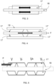
- FIG 4 depicts an embodiment according to the present disclosure in which the piezo elements 17, 17' are configured to operate in shear mode such that the direction of the shear movement is in the same direction as the flow F of molten target material though the conduit 18.
- the piezoelectric elements 17, 17' are shown in exaggerated shear deformation.
- the piezoelectric elements 17, 17' are shown as segmented and are alternately poled such that the shear deformation occurs in opposing directions along the axis of flow F of the molten target material.
- the piezo elements 17, 17' are cylinders surrounding the conduit 18.
- a pre-load tube 19 is provided surrounding the piezo elements 17, 17' and is configured to retain the piezo elements 17, 17' in the desired position such that when excited, the deformation of the piezo elements 17, 17' caused deformation of the conduit 18.
- a pre-load tube 19 is provided surrounding the piezo elements 17, 17' and is configured to retain the piezo elements 17, 17' in the desired position such that when excited, the deformation of the piezo elements 17, 17' caused deformation of the conduit 18.
- Figure 5 depicts an embodiment of the present disclosure in which a plurality of piezo elements 17 are provided surrounding a conduit 18.
- the poling P is along the length of the conduit 18, with the potential difference applied to each piezo element 17 being alternated between positive and negative.
- the conduit 18 may held at 0V.
- a pre-load tube (not shown) may be provided.
- Figure 6 depicts one possible configuration of electrodes, with a ground electrode 20 (shown as a dashed line) being provided around the central conduit 18 and secondary electrodes 21 configured to provided alternating positive and negative voltages along the conduit 18. The direction of the electric fields is shown by the black arrows between the ground electrode 20 and the secondary electrodes 21.
- a ground electrode 20 shown as a dashed line
- secondary electrodes 21 configured to provided alternating positive and negative voltages along the conduit 18.
- the direction of the electric fields is shown by the black arrows between the ground electrode 20 and the secondary electrodes 21.
- Figure 7 is a schematic representation of the configuration which would be adopted by free piezo elements 17 should then not be attached to the conduit 18 and/or constrained by a pre-load tube (not shown).
- a pre-load tube (not shown).
- the shear deformation of the piezo elements 17 is able to deform the conduit 18, and consequently perturb the velocity of molten target material flowing through the conduit.
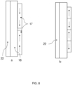
- Figure 8a and Figure 8b depict two embodiments of the present disclosure.
- a conduit 18 is surrounded by piezo elements 17.
- the piezo elements 17 are polarized (as shown by the black arrows within the piezo elements) along the direction of the conduit 18, with some being parallel and others being anti-parallel.
- Within the conduit 18 is a molten target material 22. It will be appreciated that a pre-load tube (not shown) may be provided at least partially surrounding the piezo elements 17.
- a molten target material 22 such as molten tin
- conduit 18 a molten target material 22
- the piezo elements 17 which surround the conduit 18 and are poled in the direction of the molten target material flow are exposed to an electric field at right angles to the poling such that the piezo elements 17 deform in shear mode in the same direction as the molten target material flow.
- the effect of the piezo element 17 operating in shear mode is that the velocity of the molten target material is perturbed such that the flow forms droplets upon leaving the conduit 18.
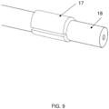
- Figure 9 depicts an embodiment in which a piezo element 17 partially surrounds the conduit 18.
- the piezo element 17 in this embodiment is in a c-shaped configuration with a circumferential gap. Although one piezo element 17 is shown, it will be appreciated that there may be any number of piezo elements 17.
- the present invention provides for systems and methods for producing a stream of droplets of a molten target material.
- Sensitivity is a measure of how much energy can be transferred to the molten target material for a given potential difference. As such, having a higher sensitivity at higher frequencies means that the transfer of energy from the piezo elements is more efficient.
Landscapes
- Physics & Mathematics (AREA)
- Optics & Photonics (AREA)
- Engineering & Computer Science (AREA)
- Plasma & Fusion (AREA)
- Exposure And Positioning Against Photoresist Photosensitive Materials (AREA)
- X-Ray Techniques (AREA)
Priority Applications (5)
| Application Number | Priority Date | Filing Date | Title |
|---|---|---|---|
| EP23174083.8A EP4465768A1 (de) | 2023-05-17 | 2023-05-17 | Tropfenerzeuger |
| CN202480032197.9A CN121286103A (zh) | 2023-05-17 | 2024-04-18 | 液滴发生器 |
| KR1020257038328A KR20260012216A (ko) | 2023-05-17 | 2024-04-18 | 액적 생성기 |
| PCT/EP2024/060652 WO2024235562A1 (en) | 2023-05-17 | 2024-04-18 | Droplet generator |
| TW113117524A TW202450369A (zh) | 2023-05-17 | 2024-05-13 | 液滴產生器 |
Applications Claiming Priority (1)
| Application Number | Priority Date | Filing Date | Title |
|---|---|---|---|
| EP23174083.8A EP4465768A1 (de) | 2023-05-17 | 2023-05-17 | Tropfenerzeuger |
Publications (1)
| Publication Number | Publication Date |
|---|---|
| EP4465768A1 true EP4465768A1 (de) | 2024-11-20 |
Family
ID=86386815
Family Applications (1)
| Application Number | Title | Priority Date | Filing Date |
|---|---|---|---|
| EP23174083.8A Withdrawn EP4465768A1 (de) | 2023-05-17 | 2023-05-17 | Tropfenerzeuger |
Country Status (5)
| Country | Link |
|---|---|
| EP (1) | EP4465768A1 (de) |
| KR (1) | KR20260012216A (de) |
| CN (1) | CN121286103A (de) |
| TW (1) | TW202450369A (de) |
| WO (1) | WO2024235562A1 (de) |
Citations (3)
| Publication number | Priority date | Publication date | Assignee | Title |
|---|---|---|---|---|
| US4825227A (en) * | 1988-02-29 | 1989-04-25 | Spectra, Inc. | Shear mode transducer for ink jet systems |
| US20150206738A1 (en) * | 2014-01-21 | 2015-07-23 | Sematech, Inc. | Surface Cleaning Method and Apparatus Using Surface Acoustic Wave Devices |
| US20200079696A1 (en) * | 2017-05-12 | 2020-03-12 | Xaar Technology Limited | Ceramic |
Family Cites Families (4)
| Publication number | Priority date | Publication date | Assignee | Title |
|---|---|---|---|---|
| US4887100A (en) * | 1987-01-10 | 1989-12-12 | Am International, Inc. | Droplet deposition apparatus |
| US6505920B1 (en) * | 1999-06-17 | 2003-01-14 | Scitex Digital Printing, Inc. | Synchronously stimulated continuous ink jet head |
| EP1872952A1 (de) * | 2006-06-28 | 2008-01-02 | Océ-Technologies B.V. | Tintenstrahldruckkopf mit einem akustischen Filter |
| JP5171702B2 (ja) * | 2009-03-18 | 2013-03-27 | 東芝テック株式会社 | インクジェットヘッド |
-
2023
- 2023-05-17 EP EP23174083.8A patent/EP4465768A1/de not_active Withdrawn
-
2024
- 2024-04-18 CN CN202480032197.9A patent/CN121286103A/zh active Pending
- 2024-04-18 WO PCT/EP2024/060652 patent/WO2024235562A1/en not_active Ceased
- 2024-04-18 KR KR1020257038328A patent/KR20260012216A/ko active Pending
- 2024-05-13 TW TW113117524A patent/TW202450369A/zh unknown
Patent Citations (3)
| Publication number | Priority date | Publication date | Assignee | Title |
|---|---|---|---|---|
| US4825227A (en) * | 1988-02-29 | 1989-04-25 | Spectra, Inc. | Shear mode transducer for ink jet systems |
| US20150206738A1 (en) * | 2014-01-21 | 2015-07-23 | Sematech, Inc. | Surface Cleaning Method and Apparatus Using Surface Acoustic Wave Devices |
| US20200079696A1 (en) * | 2017-05-12 | 2020-03-12 | Xaar Technology Limited | Ceramic |
Non-Patent Citations (1)
| Title |
|---|
| WILLIAMS G ET AL: "Non-planar interconnect", CIRCUIT WORLD, EMERALD GROUP PUBLISHING LIMITED, GB, vol. 31, no. 2, 1 January 2005 (2005-01-01), pages 10 - 14, XP007901380, ISSN: 0305-6120, DOI: 10.1108/03056120510571798 * |
Also Published As
| Publication number | Publication date |
|---|---|
| TW202450369A (zh) | 2024-12-16 |
| KR20260012216A (ko) | 2026-01-26 |
| WO2024235562A1 (en) | 2024-11-21 |
| CN121286103A (zh) | 2026-01-06 |
Similar Documents
| Publication | Publication Date | Title |
|---|---|---|
| CN101911839B (zh) | 辐射源、光刻设备以及器件制造方法 | |
| US9442380B2 (en) | Method and apparatus for generating radiation | |
| CN103765998B (zh) | 辐射源的燃料液滴束流生成装置、光刻设备和促进辐射源的燃料液滴的聚结的方法 | |
| US8890099B2 (en) | Radiation source and method for lithographic apparatus for device manufacture | |
| TW201732453A (zh) | 用於微影設備之液滴產生器、極紫外線源及微影設備 | |
| JP6086676B2 (ja) | 放射源 | |
| JP2010212685A (ja) | 放射源、リソグラフィ装置、およびデバイス製造方法 | |
| CN103019036B (zh) | 辐射源 | |
| WO2017121573A1 (en) | Droplet generator for lithographic apparatus, euv source and lithographic apparatus | |
| EP1633171B1 (de) | Vorrichtung zur Erzeugung von Strahlung, Lithographiegerät, Verfahren zur Herstellung eines Bauteils und dieses | |
| US12295088B2 (en) | Hybrid droplet generator for extreme ultraviolet light sources in lithographic radiation systems | |
| EP4465768A1 (de) | Tropfenerzeuger | |
| JP5486797B2 (ja) | 極端紫外光源装置 | |
| US20070069159A1 (en) | Electromagnetic radiation source, lithographic apparatus, device manufacturing method and device manufactured thereby | |
| US20250275046A1 (en) | Fuel droplet nozzle assembly | |
| US12339214B2 (en) | Apparatus for and method of monitoring droplets in a droplet stream | |
| CN101690419B (zh) | 光刻设备和器件制造方法 | |
| CN120958388A (zh) | 用于在光刻中使用的静电夹具 |
Legal Events
| Date | Code | Title | Description |
|---|---|---|---|
| PUAI | Public reference made under article 153(3) epc to a published international application that has entered the european phase |
Free format text: ORIGINAL CODE: 0009012 |
|
| STAA | Information on the status of an ep patent application or granted ep patent |
Free format text: STATUS: THE APPLICATION HAS BEEN PUBLISHED |
|
| AK | Designated contracting states |
Kind code of ref document: A1 Designated state(s): AL AT BE BG CH CY CZ DE DK EE ES FI FR GB GR HR HU IE IS IT LI LT LU LV MC ME MK MT NL NO PL PT RO RS SE SI SK SM TR |
|
| STAA | Information on the status of an ep patent application or granted ep patent |
Free format text: STATUS: THE APPLICATION IS DEEMED TO BE WITHDRAWN |
|
| 18D | Application deemed to be withdrawn |
Effective date: 20250521 |