EP4465756A2 - Rrc-basierte benutzerdatenübertragung im inaktiven zustand - Google Patents
Rrc-basierte benutzerdatenübertragung im inaktiven zustand Download PDFInfo
- Publication number
- EP4465756A2 EP4465756A2 EP24205285.0A EP24205285A EP4465756A2 EP 4465756 A2 EP4465756 A2 EP 4465756A2 EP 24205285 A EP24205285 A EP 24205285A EP 4465756 A2 EP4465756 A2 EP 4465756A2
- Authority
- EP
- European Patent Office
- Prior art keywords
- message
- user data
- network
- transmission
- inactive state
- Prior art date
- Legal status (The legal status is an assumption and is not a legal conclusion. Google has not performed a legal analysis and makes no representation as to the accuracy of the status listed.)
- Pending
Links
- 230000005540 biological transmission Effects 0.000 title claims abstract description 148
- 230000004044 response Effects 0.000 claims abstract description 141
- 238000000034 method Methods 0.000 claims description 131
- 230000001960 triggered effect Effects 0.000 claims description 3
- 230000007704 transition Effects 0.000 abstract description 89
- 238000012545 processing Methods 0.000 description 47
- 238000004891 communication Methods 0.000 description 31
- 230000010267 cellular communication Effects 0.000 description 21
- 238000005516 engineering process Methods 0.000 description 13
- 230000009471 action Effects 0.000 description 11
- 230000001413 cellular effect Effects 0.000 description 7
- 230000006399 behavior Effects 0.000 description 6
- 230000008569 process Effects 0.000 description 6
- 238000010586 diagram Methods 0.000 description 5
- 238000007726 management method Methods 0.000 description 5
- 238000003491 array Methods 0.000 description 4
- 230000009977 dual effect Effects 0.000 description 4
- 230000007246 mechanism Effects 0.000 description 4
- 238000012986 modification Methods 0.000 description 4
- 230000004048 modification Effects 0.000 description 4
- 230000006870 function Effects 0.000 description 3
- 230000001939 inductive effect Effects 0.000 description 2
- 230000000977 initiatory effect Effects 0.000 description 2
- 101000741965 Homo sapiens Inactive tyrosine-protein kinase PRAG1 Proteins 0.000 description 1
- 102100038659 Inactive tyrosine-protein kinase PRAG1 Human genes 0.000 description 1
- 239000008186 active pharmaceutical agent Substances 0.000 description 1
- 238000013459 approach Methods 0.000 description 1
- 239000000969 carrier Substances 0.000 description 1
- 238000004590 computer program Methods 0.000 description 1
- 230000008878 coupling Effects 0.000 description 1
- 238000010168 coupling process Methods 0.000 description 1
- 238000005859 coupling reaction Methods 0.000 description 1
- 125000004122 cyclic group Chemical group 0.000 description 1
- 238000013500 data storage Methods 0.000 description 1
- GVVPGTZRZFNKDS-JXMROGBWSA-N geranyl diphosphate Chemical compound CC(C)=CCC\C(C)=C\CO[P@](O)(=O)OP(O)(O)=O GVVPGTZRZFNKDS-JXMROGBWSA-N 0.000 description 1
- 238000009434 installation Methods 0.000 description 1
- 230000007774 longterm Effects 0.000 description 1
- 238000010295 mobile communication Methods 0.000 description 1
- 230000003287 optical effect Effects 0.000 description 1
- 229920001690 polydopamine Polymers 0.000 description 1
- 230000008054 signal transmission Effects 0.000 description 1
- 239000004984 smart glass Substances 0.000 description 1
- 230000008093 supporting effect Effects 0.000 description 1
- 238000012546 transfer Methods 0.000 description 1
- 238000013519 translation Methods 0.000 description 1
Images









Classifications
-
- H—ELECTRICITY
- H04—ELECTRIC COMMUNICATION TECHNIQUE
- H04W—WIRELESS COMMUNICATION NETWORKS
- H04W72/00—Local resource management
- H04W72/12—Wireless traffic scheduling
- H04W72/1263—Mapping of traffic onto schedule, e.g. scheduled allocation or multiplexing of flows
- H04W72/1268—Mapping of traffic onto schedule, e.g. scheduled allocation or multiplexing of flows of uplink data flows
-
- H—ELECTRICITY
- H04—ELECTRIC COMMUNICATION TECHNIQUE
- H04W—WIRELESS COMMUNICATION NETWORKS
- H04W76/00—Connection management
- H04W76/20—Manipulation of established connections
- H04W76/27—Transitions between radio resource control [RRC] states
-
- H—ELECTRICITY
- H04—ELECTRIC COMMUNICATION TECHNIQUE
- H04W—WIRELESS COMMUNICATION NETWORKS
- H04W28/00—Network traffic management; Network resource management
- H04W28/02—Traffic management, e.g. flow control or congestion control
- H04W28/0278—Traffic management, e.g. flow control or congestion control using buffer status reports
-
- H—ELECTRICITY
- H04—ELECTRIC COMMUNICATION TECHNIQUE
- H04W—WIRELESS COMMUNICATION NETWORKS
- H04W72/00—Local resource management
- H04W72/20—Control channels or signalling for resource management
- H04W72/21—Control channels or signalling for resource management in the uplink direction of a wireless link, i.e. towards the network
-
- H—ELECTRICITY
- H04—ELECTRIC COMMUNICATION TECHNIQUE
- H04W—WIRELESS COMMUNICATION NETWORKS
- H04W74/00—Wireless channel access
- H04W74/002—Transmission of channel access control information
-
- H—ELECTRICITY
- H04—ELECTRIC COMMUNICATION TECHNIQUE
- H04W—WIRELESS COMMUNICATION NETWORKS
- H04W76/00—Connection management
- H04W76/20—Manipulation of established connections
- H04W76/22—Manipulation of transport tunnels
-
- H—ELECTRICITY
- H04—ELECTRIC COMMUNICATION TECHNIQUE
- H04W—WIRELESS COMMUNICATION NETWORKS
- H04W76/00—Connection management
- H04W76/30—Connection release
- H04W76/32—Release of transport tunnels
-
- H—ELECTRICITY
- H04—ELECTRIC COMMUNICATION TECHNIQUE
- H04W—WIRELESS COMMUNICATION NETWORKS
- H04W76/00—Connection management
- H04W76/10—Connection setup
- H04W76/19—Connection re-establishment
Definitions
- the present disclosure relates to the field of wireless communication, and more particularly, to mechanisms enabling a user equipment (UE) device to perform user data transmission and/or reception (especially of small data parcels) while remaining in an inactive state.
- UE user equipment
- a wireless UE device in an inactive state may not be able to transmit and/or receive user data without first transitioning to a connected state.
- the time required for this transition is non-trivial.
- RRC Radio Resource Control
- a method for operating a user equipment (UE) device may include one or more of the following operations. While the UE device is in an inactive state, the UE device may transmit information to a network, where the information includes a Radio Resource Control (RRC) message.
- RRC Radio Resource Control
- the RRC message may include an indication of the UE device's intent to perform transmission and/or reception of user data with the network during the inactive state.
- the RRC message may be an RRC resume request message, and the information may include: at least a portion of the user data; and/or a buffer status report.
- the RRC message may include a cause indicator field that indicates the cause for which the RRC message is being transmitted.
- the cause indicator field may be set to a value indicating data transmission (or small data transmission) as the cause.
- the information transmitted by the UE device may be (or may be contained within) a Medium Access Control Protocol Data Unit (MAC PDU).
- MAC PDU Medium Access Control Protocol Data Unit
- the UE device may receive a response message from the network.
- the response message may induce a state transition in the UE device. Different state transmissions may be induced by different types of response message.
- the response message may be a release message, and may induce a state transition to an idle state.
- the response message may be a release message with a suspend configuration, and may induce a state transition to a legacy inactive state.
- the response message may be a resume message, and may induce a state transition to a connected state.
- the response message may be a setup message, and may induce a state transition to a connected state.
- the response message may cause the UE device to stay in the inactive state and enter a subsequent user data transmission mode.
- the UE device may transmit and/or receive additional user data (to/from the base station) while remaining in the inactive state.
- the response message may implicitly indicate that forwarding of the user data to a core network was successful.
- the response message may explicitly indicate whether forwarding of the user data to a core network was successful.
- a non-transitory memory medium may store program instructions.
- the program instructions when executed by processing circuitry, may cause the processing circuitry to perform any of the method embodiments described above.
- a user equipment (UE) device may include a radio subsystem; processing circuitry coupled to the radio subsystem; and memory storing program instructions.
- the program instructions when executed by the processing circuitry, may cause the UE device to perform any of the method embodiments described above.
- a method for operating a base station may include one or more of the following operations. While a user equipment (UE) device is in an inactive state, the base station may receive information from the UE device, where the information includes a Radio Resource Control (RRC) message.
- RRC Radio Resource Control
- the RRC message may include an indication of the LTE device's intent to perform transmission and/or reception of user data with the network during the inactive state.
- the RRC message may be an RRC resume request message.
- the information may include: at least a portion of the user data; and/or a buffer status report.
- the RRC message may include a cause indicator field that indicates the cause for the RRC message.
- the cause indicator field may be set to a value indicating data transmission (or small data transmission) as the cause.
- the message may be (or may be contained in) a Medium Access Control Protocol Data Unit (MAC PDU).
- MAC PDU Medium Access Control Protocol Data Unit
- the method may also include, while the UE device is in the inactive state, transmitting a response message to the UE device.
- the response message may induce a state transition in the UE device. Different state transmissions may be induced by different types of response message.
- the response message may be a release message, and may induce a state transition to an idle state.
- the response message may be a release message with a suspend configuration, and may induce a state transition to a legacy inactive state.
- the response message may be a resume message, and may induce a state transition to a connected state.
- the response message may be a setup message, and may induce a state transition to a connected state.
- the response message may cause the UE device to stay in the inactive state and enter a subsequent user data transmission mode. While the UE device remains in the inactive state and the subsequent user data transmission mode, the base station may transmit and/or receive additional user data to/from the UE device.
- the response message may implicitly indicate that forwarding of the user data to a core network was successful.
- the response message may explicitly indicate whether forwarding of the user data to a core network was successful.
- a non-transitory memory medium may store program instructions.
- the program instructions when executed by processing circuitry, may cause the processing circuitry to perform any of the method embodiments described above.
- a base station may include a radio subsystem; processing circuitry coupled to the radio subsystem; and memory storing program instructions.
- the program instructions when executed by the processing circuitry, may cause the base station to perform any of the method embodiments described above.
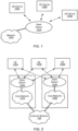
- Figures 1 and 2 illustrate exemplary (and simplified) wireless communication systems. It is noted that the systems of Figures 1 and 2 are merely examples of certain possible systems, and various embodiments may be implemented in any of various ways, as desired.
- the wireless communication system of Figure 1 includes a base station 102A which communicates over a transmission medium with one or more user equipment (UE) devices 106A, 106B, etc., through 106N. Each of the user equipment devices may be referred to herein as "user equipment” (UE).
- UE user equipment
- base station 102B in addition to the base station 102A, base station 102B also communicates (e.g., simultaneously or concurrently) over a transmission medium with the LTE devices 106A, 106B, etc., through 106N.
- the base stations 102A and 102B may be base transceiver stations (BTSs) or cell sites, and may include hardware that enables wireless communication with the user devices 106A through 106N.
- Each base station 102 may also be equipped to communicate with a core network 100 (e.g., base station 102A may be coupled to core network 100A, while base station 102B may be coupled to core network 100B), which may be a core network of a cellular service provider.
- Each core network 100 may be coupled to one or more external networks (such as external network 108), which may include the Internet, a Public Switched Telephone Network (PSTN), or any other network.
- PSTN Public Switched Telephone Network
- the base station 102A may facilitate communication between the user devices and/or between the user devices and the network 100A; in the system of Figure 2 , the base station 102B may facilitate communication between the user devices and/or between the user devices and the network 100B.
- the base stations 102A and 102B and the user devices may be configured to communicate over the transmission medium using any of various radio access technologies (RATs), also referred to as wireless communication technologies, or telecommunication standards, such as GSM, UMTS (WCDMA), LTE, LTE-Advanced (LTE-A), 3GPP2 CDMA2000 (e.g., 1xRTT, 1xEV-DO, HRPD, eHRPD), Wi-Fi, WiMAX etc.
- RATs radio access technologies
- GSM Global System for Mobile communications
- WCDMA UMTS
- LTE Long Term Evolution
- LTE-A LTE-Advanced
- 3GPP2 CDMA2000 e.g., 1xRTT, 1xEV-DO, HRPD, eHRPD
- Wi-Fi WiMAX etc.
- base station 102A and core network 100A may operate according to a first cellular communication standard (e.g., LTE) while base station 102B and core network 100B operate according to a second (e.g., different) cellular communication standard (e.g., GSM, UMTS, and/or one or more CDMA2000 cellular communication standards).
- the two networks may be controlled by the same network operator (e.g., cellular service provider or "carrier"), or by different network operators.
- the two networks may be operated independently of one another (e.g., if they operate according to different cellular communication standards), or may be operated in a somewhat coupled or tightly coupled manner.
- base stations 102A and 102B might operate according to different cellular communication standards but couple to the same core network.
- multi-mode base stations capable of simultaneously supporting different cellular communication technologies e.g., LTE and CDMA 1xRTT, GSM and UMTS, or any other combination of cellular communication technologies
- LTE and CDMA 1xRTT e.g., LTE and CDMA 1xRTT, GSM and UMTS, or any other combination of cellular communication technologies
- base station 102A and base station 102B may operate according to the same wireless communication technology (or an overlapping set of wireless communication technologies).
- base station 102A and core network 100A may be operated by one cellular service provider independently of base station 102B and core network 100B, which may be operated by a different (e.g., competing) cellular service provider.
- the UE devices 106A-106N might communicate with the base stations 102A-102B independently, possibly by utilizing separate subscriber identities to communicate with different carriers' networks.
- a UE 106 may be capable of communicating using multiple wireless communication standards.
- a UE 106 might be configured to communicate using either or both of a 3GPP cellular communication standard (such as LTE) or a 3GPP2 cellular communication standard (such as a cellular communication standard in the CDMA2000 family of cellular communication standards).
- a LTE 106 might be configured to communicate using different 3GPP cellular communication standards (such as two or more of GSM, UMTS, LTE, or LTE-A).
- a UE 106 might be configured to communicate with base station 102A (and/or other base stations) according to a first cellular communication standard (e.g., LTE) and might also be configured to communicate with base station 102B (and/or other base stations) according to a second cellular communication standard (e.g., one or more CDMA2000 cellular communication standards, UMTS, GSM, etc.).
- a first cellular communication standard e.g., LTE
- a second cellular communication standard e.g., one or more CDMA2000 cellular communication standards, UMTS, GSM, etc.
- Base stations 102A and 102B and other base stations operating according to the same or different cellular communication standards may thus be provided as one or more networks of cells, which may provide continuous or nearly continuous overlapping service to UEs 106A-106N and similar devices over a wide geographic area via one or more cellular communication standards.
- a UE 106 might also or alternatively be configured to communicate using WLAN, Bluetooth, one or more global navigational satellite systems (GNSS, e.g., GPS or GLONASS), one and/or more mobile television broadcasting standards (e.g., ATSC-M/H or DVB-H), etc.
- GNSS global navigational satellite systems
- GLONASS global navigational satellite systems
- ATSC-M/H ATSC-M/H or DVB-H
- Other combinations of wireless communication standards are also possible.
- Figure 3 illustrates user equipment 106 (e.g., one of the devices 106A through 106N) in communication with a base station 102 (e.g., one of the base stations 102A or 102B).
- the UE 106 may be a device with wireless network connectivity such as a mobile phone, a hand-held device, a computer or a tablet, a wearable device or virtually any type of wireless device.
- the UE may include a processor that is configured to execute program instructions stored in memory.
- the UE may perform any of the method embodiments described herein by executing such stored instructions.
- the UE may include a programmable hardware element such as an FPGA (field-programmable gate array) that is configured to perform any of the method embodiments described herein, or any portion of any of the method embodiments described herein.
- FPGA field-programmable gate array
- the UE 106 may be configured to communicate using any of multiple wireless communication protocols.
- the UE 106 may be configured to communicate using two or more of GSM, UMTS (W-CDMA, TD-SCDMA, etc.), CDMA2000 (1xRTT, 1xEV-DO, HRPD, eHRPD, etc.), LTE, LTE-A, WLAN, or GNSS.
- GSM Global System for Mobile communications
- the UE 106 may include one or more antennas for communicating using one or more wireless communication protocols.
- one or more parts of a receive and/or transmit chain may be shared between multiple wireless communication standards; for example, the UE 106 might be configured to communicate using either (or both) of GSM or LTE using a single shared radio.
- the shared radio may include a single antenna, or may include multiple antennas (e.g., for MIMO or beamforming) for performing wireless communications.
- MIMO is an acronym for Multi-Input Multiple-Output.
- FIG. 4 illustrates an example of a block diagram of a UE 106.
- the UE 106 may include a system on chip (SOC) 300, which may include portions for various purposes.
- the SOC 300 may include processor(s) 302 which may execute program instructions for the UE 106 and display circuitry 304 which may perform graphics processing and provide display signals to the display 345.
- the processor(s) 302 may also be coupled to memory management unit (MMU) 340, which may be configured to receive addresses from the processor(s) 302 and translate those addresses to locations in memory (e.g., memory 306, read only memory (ROM) 350, NAND flash memory 310) and/or to other circuits or devices, such as the display circuitry 304, radio 330, connector I/F 320, and/or display 345.
- MMU memory management unit
- the MMU 340 may be configured to perform memory protection and page table translation or set up. In some embodiments, the MMU 340 may be included as a portion of the processor(s) 302.
- the SOC 300 may be coupled to various other circuits of the UE 106.
- the UE 106 may include various types of memory (e.g., including Flash memory 310), a connector interface 320 (e.g., for coupling to a computer system, dock, charging station, etc.), the display 345, and radio 330.
- the radio 330 may include one or more RF chains. Each RF chain may include a transmit chain, a receive chain, or both. For example, radio 330 may include two RF chains to support dual connectivity with two base stations (or two cells).
- the radio may be configured to support wireless communication according to one or more wireless communication standards, e.g., one or more of GSM, UMTS, LTE, LTE-A, WCDMA, CDMA2000, Bluetooth, Wi-Fi, GPS, etc.
- the radio 330 couples to antenna subsystem 335, which includes one or more antennas.
- the antenna subsystem 335 may include a plurality of antennas to support applications such as dual connectivity or MIMO or beamforming.
- the antenna subsystem 335 transmits and receives radio signals to/from one or more base stations or devices through the radio propagation medium, which is typically the atmosphere.
- the processor(s) 302 may include a baseband processor to generate uplink baseband signals and/or to process downlink baseband signals.
- the processor(s) 302 may be configured to perform data processing according to one or more wireless telecommunication standards, e.g., one or more of GSM, UMTS, LTE, LTE-A, WCDMA, CDMA2000, Bluetooth, Wi-Fi, GPS, etc.
- the UE 106 may also include one or more user interface elements.
- the user interface elements may include any of various elements, such as display 345 (which may be a touchscreen display), a keyboard (which may be a discrete keyboard or may be implemented as part of a touchscreen display), a mouse, a microphone and/or speakers, one or more cameras, one or more sensors, one or more buttons, sliders, and/or dials, and/or any of various other elements capable of providing information to a user and/or receiving /interpreting user input.
- the UE 106 may also include one or more subscriber identity modules (SIMs) 360.
- SIMs subscriber identity modules
- Each of the one or more SIMs may be implemented as an embedded SIM (eSIM), in which case the SIM may be implemented in device hardware and/or software.
- the UE 106 may include an embedded UICC (eUICC), e.g., a device which is built into the UE 106 and is not removable.
- eUICC embedded UICC
- the eUICC may be programmable, such that one or more eSIMs may be implemented on the eUICC.
- the eSIM may be installed in UE 106 software, e.g., as program instructions stored on a memory medium (such as memory 306 or Flash 310) executing on a processor (such as processor 302) in the UE 106.
- a SIM 360 may be an application which executes on a Universal Integrated Circuit Card (UICC).
- UICC Universal Integrated Circuit Card
- one or more of the SIMs 360 may be implemented as removable SIM cards.
- the processor 302 of the UE device 106 may be configured to implement part or all of the methods described herein, e.g., by executing program instructions stored on a memory medium (e.g., a non-transitory computer-readable memory medium).
- processor 302 may be configured as or include: a programmable hardware element, such as an FPGA (Field Programmable Gate Array); or an ASIC (Application Specific Integrated Circuit); or a combination thereof.
- FIG. 5 illustrates a block diagram of a base station 102. It is noted that the base station of Figure 5 is merely one example of a possible base station. As shown, the base station 102 may include processor(s) 404 which may execute program instructions for the base station 102. The processor(s) 404 may also be coupled to memory management unit (MMU) 440, which may be configured to receive addresses from the processor(s) 404 and translate those addresses to locations in memory (e.g., memory 460 and read only memory ROM 450) or to other circuits or devices.
- MMU memory management unit
- the base station 102 may include at least one network port 470.
- the network port 470 may be configured to couple to a telephone network and provide access (for a plurality of devices, such as UE devices 106) to the telephone network, as described above in Figures 1 and 2 .
- the network port 470 may also or alternatively be configured to couple to a cellular network, e.g., a core network of a cellular service provider.
- the core network may provide mobility related services and/or other services to a plurality of devices, such as UE devices 106.
- the network port 470 may couple to a telephone network via the core network, and/or the core network may provide a telephone network (e.g., among other UE devices serviced by the cellular service provider).
- the base station 102 may include a radio 430 having one or more RF chains. Each RF chain may include a transmit chain, a receive chain, or both. (For example, the base station 102 may include at least one RF chain per sector or cell.)
- the radio 430 couples to antenna subsystem 434, which includes one or more antennas. Multiple antennas would be needed, e.g., to support applications such as MIMO or beamforming.
- the antenna subsystem 434 transmits and receives radio signals to/from UEs through the radio propagation medium (typically the atmosphere).
- the processor(s) 404 may include a baseband processor to generate downlink baseband signals and/or to process uplink baseband signals.
- the baseband processor 430 may be configured to operate according to one or more wireless telecommunication standards, including, but not limited to, GSM, LTE, WCDMA, CDMA2000, etc.
- the processor(s) 404 of the base station 102 may be configured to implement part or all of the methods described herein, e.g., by executing program instructions stored on a memory medium (e.g., a non-transitory computer-readable memory medium).
- the processor(s) 404 may include: a programmable hardware element, such as an FPGA (Field Programmable Gate Array); or an ASIC (Application Specific Integrated Circuit); or a combination thereof.
- a wireless user equipment (UE) device 600 may be configured as shown in Figure 6 .
- LTE device 600 may include: a radio subsystem 605 for performing wireless communication; and a processing element 610 operatively coupled to the radio subsystem.
- UE device 600 may also include any subset of the UE features described above, e.g., in connection with Figures 1-4 .
- the radio subsystem 605 may include one or more RF chains, e.g., as variously described above. Each RF chain may be configured to receive signals from the radio propagation channel and/or transmit signals onto the radio propagation channel. Thus, each RF chain may include a transmit chain and/or a receive chain.
- the radio subsystem 605 may be coupled to one or more antennas (or, one or more arrays of antennas) to facilitate signal transmission and reception. Each RF chain (or, some of the RF chains) may be tunable to a desired frequency, thus allowing the RF chain to receive or transmit at different frequencies at different times.
- the processing element 610 may be coupled to the radio subsystem, and may be configured as variously described above. (For example, processing element may be realized by processor(s) 302.) The processing element may be configured to control the state of each RF chain in the radio subsystem.
- the processing element may include one or more baseband processors to (a) generate baseband signals to be transmitted by the radio subsystem and/or (b) process baseband signals provided by the radio subsystem.
- the processing element may direct a first RF chain to communicate with a first base station using a first radio access technology and direct a second RF chain to communicate with a second base station using a second radio access technology.
- the first RF chain may communicate with an LTE eNB
- the second RF chain may communicate with a gNB of 5G New Radio (NR).
- the link with the LTE eNB may be referred to as the LTE branch.
- the link with the gNB may be referred to as the NR branch.
- the processing element may include a first subcircuit for baseband processing with respect to the LTE branch and a second subcircuit for baseband processing with respect to the NR branch.
- the processing element 610 may be further configured as variously described in the sections below.
- a wireless base station 700 of a wireless network may be configured as shown in Figure 7 .
- the wireless base station may include: a radio subsystem 705 for performing wireless communication over a radio propagation channel; and a processing element 710 operatively coupled to the radio subsystem.
- the wireless base station may also include any subset of the base station features described above, e.g., the features described above in connection with Figure 5 .
- the radio subsystem 710 may include one or more RF chains. Each RF chain may be tunable to a desired frequency, thus allowing the RF chain to receive or transmit at different frequencies at different times.
- the radio subsystem 710 may be coupled to an antenna subsystem, including one or more antennas, e.g., an array of antenna, or a plurality of antenna arrays.
- the radio subsystem may employ the antenna subsystem to transmit and receive radio signals to/from radio wave propagation medium.
- processing element 710 may be realized as variously described above.
- processing element 710 may be realized by processor(s) 404.
- the processing element may include one or more baseband processors to: (a) generate baseband signals to be transmitted by the radio subsystem, and/or, (b) process baseband signals provided by the radio subsystem.
- the processing element 710 may be configured to perform any of the base station method embodiments described herein.
- the behavior of a user equipment (UE) in the INACTIVE state may be described in terms of its behaviors in the control plane and the user plane.
- the INACTIVE UE may: have a network access stratum (NAS) connection to the core network, and no dedicated access stratum (AS) resource.
- the UE may retain the Radio Resource Control (RRC) configuration that it had before entering the INACTIVE state.
- RRC Radio Resource Control
- the UE may not be able to perform any dedicated data transmission/reception. If a dedicated data transmission/reception needs to be performed, the UE needs to enter the CONNECTED state.
- the gNB may page the UE via a RAN paging mechanism, to trigger the UE's transition to the CONNECTED state.
- RAN is an acronym for Radio Access Network.
- the UE may trigger a random access (RACH) procedure, to enter the CONNECTED state.
- RACH random access
- an INACTIVE UE may move within a RAN notification area (RNA) without notifying the Next Generation RAN (NG-RAN). Cell selection and re-selection may be performed in the same fashion as in the RRC IDLE state.
- RNA RAN notification area
- NG-RAN Next Generation RAN
- the UE may make different state transitions under different circumstances. For example, the gNB may cause the UE to transition from the CONNECTED state to the INACTIVE state using an RRC Release with suspend information. As another example, the gNB may cause the UE to transition from the INACTIVE state to the CONNECTED state as part of an RRC Resume procedure. As yet another example, the UE may transition from an INACTIVE state to an IDLE state (1) in response to an RRC Release or (2) when the UE cannot find a cell for camping.
- a UE may transition from the INACTIVE State to the CONNECTED state as shown in Figure 8 .
- CM is an acronym for Connection Management.
- the UE may transmit a resume request (e.g., an RRCResumeRequest) to a current gNB.
- the gNB may transmit a context retrieval request (i.e., a request for the retrieval of UE context) to a last serving gNB.
- the UE context may include UE Access Stratum (AS) configuration and variable(s) of a previous connected state.
- AS UE Access Stratum
- the UE context may be used by current gNB to decide the RRC configuration in the new accessed serving cell.
- the last serving gNB may transmit a context retrieval response, containing the requested UE context, to the current gNB.
- the current gNB may transmit a resume message (e.g., an RRCResume message) to the UE.
- a resume message e.g., an RRCResume message
- the UE may transition to an RRC-CONNECTED CM-CONNECTED state. In that state, the UE may transmit a resume complete message (e.g., an RRCResumeComplete message) to the current gNB.
- the current gNB may transmit a data forwarding address indication to the last serving gNB, and transmit a path switch request to an Access & Mobility Management Function (AMF).
- AMF Access & Mobility Management Function
- the AMF may transit a response to the path switch request to the current gNB.
- the current gNB may transmit to the last serving gNB a context release message, indicating that the UE context may be released in last serving gNB.
- Figures 9A-9E illustrate five different patterns of behavior when a UE in the INACTIVE state transmit a resume request (or attempts to resume a suspended RRC connection).
- the attempt to resume may be interpreted as successful.
- Figure 9B illustrates a case of resume with fallback to setup.
- Figure 9E the attempt to resume is rejected by the network.
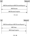
- Figure 9A illustrates a procedure in which the UE transitions from the INACTIVE state to a CONNECTED state, according to some embodiments. This procedure may be followed when the network is able to fetch UE context.
- the UE may initiate an attempt to resume a suspended RRC connection by sending a resume request (such as an RRCResumeRequest or an RRCResumeRequest1, e.g., as defined in 3GPP TS 38.331), Release 15.
- the network may reply to the UE with a resume message (e.g., an RRCResume message).
- the UE may transition to the CONNECTED state; and send a resume complete message (e.g., an RRCResumeComplete message) to the network, indicating that the process of resuming the connection is complete.
- Figure 9B illustrates a procedure in which the UE transitions from the INACTIVE state to a CONNECTED state, according to some embodiments. This procedure may be followed when the network cannot fetch UE context.
- the UE may initiate an attempt to resume a suspended RRC connection by sending a resume request.
- the network may reply to the LTE with a connection setup message (e.g., an RRCSetup message).
- the UE may transition to the CONNECTED state; and send a setup complete message (e.g., an RRCSetupComplete message) to the network, indicating that the process of setting up the connection is complete.
- a setup complete message e.g., an RRCSetupComplete message
- Figure 9C illustrates a procedure in which the UE transitions from the INACTIVE state to an IDLE state, according to some embodiments. This procedure may be followed when the network is able to fetch the UE context. From the INACTIVE state, the UE may initiate an attempt to resume a suspended RRC connection by sending a resume request. In response to receiving the resume request, the network may reply to the UE with a release message (e.g., an RRCRelease message). In response to receiving the release message, the UE may transition to the IDLE state.
- a release message e.g., an RRCRelease message
- Figure 9D illustrates a procedure in which the UE makes a null transition from the INACTIVE state to the INACTIVE state, according to some embodiments. This procedure may be followed when the network is able to fetch the UE context. From the INACTIVE state, the UE may initiate an attempt to resume a suspended RRC connection by sending a resume request. In response to receiving the resume request, the network may reply to the UE by sending a release message (e.g., an RRCRelease message) with a suspend configuration. In response to receiving the release message with suspend configuration, the UE may remain in the INACTIVE state.
- a release message e.g., an RRCRelease message
- Figure 9E illustrates a procedure in which the UE makes a null transition from the INACTIVE state to the INACTIVE state. This procedure may be followed when the network may not be able to fetch the UE context. From the INACTIVE state, the UE may initiate an attempt to resume a suspended RRC connection by sending a resume request. In response to receiving the resume request, the network may reply to the UE by sending a reject message (e.g., an RRCReject message). In response to receiving the reject message, the UE may remain in the INACTIVE state.
- a reject message e.g., an RRCReject message
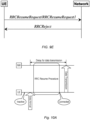
- FIG 10A illustrates a difficulty encountered when an INACTIVE UE needs to perform a user data transmission to the network in a legacy fashion.
- the UE senses data is available for uplink transmission. For example, the UE may sense the arrival of data in an uplink transmission buffer.
- the UE may trigger an RRC resume procedure.
- the resume procedure may result in the UE's transition to the CONNECTED state or the IDLE state or the INACTIVE state. No user data transmission is allowed during RRC resume procedure.
- the LTE may perform an uplink data transmission to service the waiting uplink data.
- the time delay between the data arrival event and the uplink transmission may be nontrivial. It is unfortunate that the UE needs to wait for the resume procedure to complete before transmitting, especially when the amount of data to be transmitted is small.
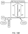
- Figure 10B illustrates a solution for the above described difficulty, according to some embodiments.
- the network and the UE may be provided with mechanisms that enable the UE to perform user data transmission(s) - uplink and/or downlink - during the RRC resume procedure, while the UE remains in the INACTIVE state.
- the UE and the network may support mechanisms enabling the UE to perform small data transmission(s) in the INACTIVE state. While in an INACTIVE state, the UE may perform small data transmissions, e.g., using one or more messages of a random access procedure.
- the base station e.g., a gNB of 3GPP NR
- the INACTIVE UE may transmit uplink user data on pre-configured PUSCH resources.
- PUSCH is an acronym for Physical Uplink Shared Channel.
- a network may configure the UE to support a small data transmission (SDT) procedure in the INACTIVE state.
- the UE may initiate the SDT procedure, e.g., by transmitting a release message with suspend configuration (e.g., an RRCRelease with SuspendConfig).
- a suspend configuration may be interpreted as a configuration to be used by the UE for transmission during the INACTIVE state.
- a serving cell (or a base station) may or may not support the SDT feature.
- a serving cell (or base station) may indicate that it supports the SDT feature, e.g., via a broadcast message.
- a UE may decode the broadcast message to determine that the serving cell (or base station) supports the SDT feature.
- the UE may determine that the serving cell (or base station) supports the SDT feature based on a previous dedicated configuration.
- the network may previously send the RRCRelease with suspend configuration to set to UE into INACTIVE state. In this message, the network may enable the SDT feature and indicate a list of applicable cells.
- the UE may trigger the SDT procedure in response to the one or conditions (e.g., configurable conditions) being satisfied.
- the action of triggering the SDT procedure may include performing an uplink transmission including a resume request message (e.g., an RRCResumeRequest message).
- the resume request message may include: the UE identity in the INACTIVE state (e.g., I-RNTI); the UE Medium Access Control Identity (MAC-I, for security checking); and an indication of access cause.
- MAC-I Medium Access Control Identity
- the resume request message may include an indication of the cause for which the UE making the request.
- the cause indication may be set to an SDT state, i.e., a state indicating that a small data transmission is requested.
- the network in response to receiving the resume request message with cause equal to SDT, may perform access control, security check and UE identification in a legacy fashion, and transmit a response message to the UE.
- the network may set the UE state to one of the following based on the kind of response message it transmits to the UE: (1) CONNECTED; (2) INACTIVE; (3) IDLE; (4) INACTIVE with subsequent transmission.
- Legacy response messages may be used to set the UE state to any of states (1), (2) and (3). However, for the state (4), a new type of RRC response message and procedure may be required.
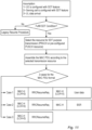
- the UE may first evaluate whether to trigger SDT procedure or legacy resume procedure.
- the UE may trigger the SDT procedure when one or more conditions (e.g., network configurable conditions) are fulfilled.
- the conditions may include one or more of the following.
- the UE may determine if the associated local channel (LCH) or data radio bearer (DRB) is configured for SDT operation.
- the UE may determine if the available data amount is less than a configured threshold.
- the UE may determine if the radio signal quality is greater than a quality threshold. If the one or more desired (or configured) conditions are not fulfilled, the UE may trigger a legacy resume procedure.
- the UE may select the SDT resource (PRACH, pre-configured PUSCH) for transmission, and assemble a MAC PDU according to the Transport Block Size (TBSize).
- TBSize Transport Block Size
- MAC PDU is an acronym for Medium Access Control - Protocol Data Unit.
- the UE may include within the MAC PDU at least the RRC message, and additionally include part of the user data and/or a buffer status report (BSR).
- the network e.g., a base station such as a gNB
- the network may indicate to the UE whether or not the user data portion that was transmitted together with the RRCResumeRequest has been successfully handled by the NW. That indication may be provided in the following ways. In a first option, the NW may explicitly indicate the data processing result (SUCCESS or FAILURE) in the response message. In a second option, the success or failure result may be implicitly indicated by the transmission or non-transmission of a special RRC response message. (Transmission of the special RRC response message may indicate success.)
- a Medium Access Control Protocol Data Uni (MAC PDU) 1210 may include one or more sub-PDU.
- Each sub-PDU may include a corresponding header (MAC-H) and a corresponding payload.
- a first sub-PDU may include a header with logical channel number (LCH) equal to zero, and a payload containing the RRC resume request.
- a second sub-PDU may include a header with a logical channel number X, e.g., different from zero, and a payload including the user data (or a portion of the user data).
- the UE may operate on the data portion as follows.
- the UE may regard the response transmission as a Radio Link Control Acknowledgement (RLC ACK), and discard the data portion.
- RLC ACK Radio Link Control Acknowledgement
- the response indicates failure, there are different options for handling the data portion.
- the UE may regards the failure as an RLC NACK (Negative Acknowledgement), and wait for the next time of RLC Protocol Data Unit (PDU) retransmission.
- RLC NACK Negative Acknowledgement
- PDU RLC Protocol Data Unit
- the UE may discard the RLC PDU, and wait for the next time of PDCP PDU retransmission.
- PDCP is an acronym for Packet Data Convergence Protocol.
- the UE may discard the RLC PDU and the PDCP PDU, and wait for the next time of PDCP SDU retransmission.
- SDU is an acronym for Service Data Unit.
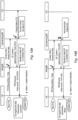
- Figures 13A-13C relate to case 1 (where an RRCRelease message is used to cause the UE to enter the IDLE state), and illustrate three different ways to indicate success or failure of the network's handling of the user data to the UE, according to some embodiments.
- a current base station e.g., a gNB of 3GPP NR
- the current base station may send a context fetch and a data forwarding request (including the user data) to a last serving base station.
- the context fetch represents a request for the last serving base station to provide the UE context.
- the last serving base station may attempt to forward the user data to the core network (CN).
- CN core network
- the last serving base station may send to the current base station the requested UE context and an indication of data forwarding success.
- the current base station may then decide to release the UE, e.g., by transmitting to the UE a release message (e.g., an RRCRelease message) including an explicit indication of data forwarding success, in which case, the UE may transition to the IDLE state.
- a release message e.g., an RRCRelease message
- the last serving base station may decide not to forward the user data to the core network (or determine that an attempt to forward the user data to the core network has failed). In that case, the last serving base station may send the UE context and an indication of data forwarding failure to the current base station. In response, the current base station may decide to release the UE, e.g., by transmitting to the UE an RRCRelease message including an explicit indication of data forwarding failure. IN response to receiving the RRCRelease message including the explicit indication of data forwarding failure, the UE may regarding its transmission of the user data as a failure, and transition to the IDLE state.
- Figure 13C shows an embodiment in which data forwarding success may be implicitly indicated by the current base station's action of transmitting the RRCRelease message.
- the UE may regard its transmission of the user data as a success, and transition to the IDLE state. If the UE does not receive the RRCRelease message within a predetermined amount of time, the UE may assume that its transmission of the user data has failed.
- Figures 14A-14C relate to case 2 (where an RRCRelease message with suspend configuration is used to cause the UE to enter a legacy INACTIVE state), and illustrate three different ways to indicate to the UE the success or failure of the network's handling of the user data, according to some embodiments.
- the legacy INACTIVE state may be interpreted as an INACTIVE state in which user data transfer is not allowed, e.g., as with the INACTIVE state defined by existing 3GPP SGNR specifications.
- the last serving base station may send the UE context and an indication of data forwarding success to the current base station.
- the current base station may to transmit to the UE an RRCRelease message with suspend configuration and an explicit indication of data forwarding success.
- the UE may regard its transmission of the user data as successful, and transition to a legacy INACTIVE state.
- the last serving base station may decide not to forward the user data to the core network (or determine that an attempt to forward the user data to the core network has failed). In that case, the last serving base station may send the LTE context and an indication of data forwarding failure to the current base station. In response, the current base station may decide to release the UE by transmitting to the UE an RRCRelease with suspend configuration and an explicit indication of data forwarding failure. In response to receiving the RRCRelease with suspend configuration and explicit indication of data forwarding failure, the UE may regard its transmission of the user data to be a success, and may transition to a legacy INACTIVE state.
- Figure 14C shows an embodiment in which the data forwarding success may be implicitly indicated by the current base station's action of transmitting an RRCRelease message with a suspend configuration.
- the UE may regard its transmission of the user data as a success, and transition to the legacy INACTIVE state. If the UE does not receive the RRCRelease with suspend configuration within a predetermined amount of time, the UE may regard its transmission of the user data as a failure.
- Figures 15A-15C relate to case 3 (where an RRCResume message is used to cause the UE to enter the CONNECTED state), and illustrate three different ways to indicate to the UE the success or failure of the network's handling of the user data, according to some embodiments.
- a current base station e.g., a gNB of 3GPP NR
- the current base station may send a context fetch and a data forwarding request (including the user data) to a last serving base station.
- the context fetch represents a request for the last serving base station to provide the UE context.
- the last serving base station may attempt to forward the user data to the core network (CN).
- CN core network
- the last serving base station may send to the current base station the requested UE context and an indication of data forwarding success.
- the current base station may then decide to release the UE by transmitting to the UE an RRCResume message including an explicit indication of data forwarding success.
- the UE may regard its transmission of the user data as successful, and transition to the CONNECTED state.
- the last serving base station may decide not to forward the user data to the core network (or determine that an attempt to forward the user data to the core network has failed). In that case, the last serving base station may send the UE context and an indication of data forwarding failure to the current base station. In response to receiving the LTE context and the indication of data forwarding failure, the current base station may decide to make the UE transition to CONNECTED state, e.g., by transmitting to the UE an RRCResume message including an explicit indication of data forwarding failure. In response to receiving the RRCResume message including the explicit indication of data forwarding failure, the UE may regard its transmission of user data as a failure, and transition to the CONNECTED state.
- Figure 15C shows an embodiment in which data forwarding success may be implicitly indicated by the current base station's action of transmitting the RRCResume message.
- the UE may regard its transmission of the user data as a success, and transition to the CONNECTED state. If the UE does not receive the RRCRelease within a predetermined amount of time, the UE may regard it transmission of the user data as a failure.
- Figures 16A and 16B relate to case 4, where an RRCSetup message is used to implicitly indicate failure of the UE's user data transmission, and to cause the UE to enter the CONNECTED state.
- the last serving base station may determine that it cannot (or will not) provide the UE context, and may respond by sending to the current base station an indication that the request for LTE context has failed.
- the current base station may decide that the UE should transition to the CONNECTED state.
- the LTE may cause this transition by transmitting to the UE a setup message (e.g., an RRCSetup message).
- the RRCSetup message implicitly indicates to the UE that its transmission of the user data was a failure.
- the LTE may regard the user data transmission as a failure, and transition to the CONNECTED state.
- the current base station may decide to make the UE transition to the CONNECTED state, e.g., without any attempt to fetch the UE context or to forward the user data to the last serving base station or the core network.
- the current base station may implicitly indicate failure of the UE's user data transmission by transmitting a setup message (e.g., an RRCSetup message) to the UE.
- a setup message e.g., an RRCSetup message
- the UE may regard its user data transmission as a failure, and transition to the CONNECTED state.
- Figures 17A and 17B relate to case 5, where an RRCReject message is used to implicitly indicate failure of the UE's user data transmission, and to cause the UE to remain in a legacy INACTIVE state.
- the last serving base station may: determine that it cannot (or will not) fetch the LTE context; decide not to forward the user data to the core network (or determine that an attempt to forward the user data to the core network has failed); and respond by sending to the current base station an indication that the request for LTE context has failed.
- the current base station may decide that the UE's request to resume connection should be rejected, e.g., due to congestion.
- the UE may cause the UE to transition to the legacy INACTIVE state by transmitting to the UE an RRCReject message.
- the RRCReject message implicitly indicates to the UE that its transmission of the user data was a failure.
- the UE may regard its user data transmission as a failure, and transition to the legacy INACTIVE state.
- the current base station may decide to make the UE transition to the legacy INACTIVE state, e.g., without any attempt to fetch the UE context or to forward the user data to the last serving base station or the core network.
- the current base station may implicitly indicate failure of the UE's user data transmission by transmitting a reject message (e.g., an RRCReject message) to the UE.
- a reject message e.g., an RRCReject message
- the UE may regard its user data transmission as a failure, and transition to the legacy INACTIVE state.
- the network may decide to keep the UE in the INACTIVE state, and enable subsequent data transmission via dedicated scheduling/transmission.
- the network may trigger the LTE to enter the subsequent data transmission mode, e.g., via an L2 or L3 command.
- state INACTIVE
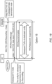
- Figure 18 illustrates an embodiment of this first option.
- the current base station may decide to cause the UE to remain in the INACTIVE state and to transition to a subsequent data transmission mode.
- the current base station may transmit an RRCResume message with an explicit indication of the INACTIVE state.
- the configuration for subsequent transmission may be provided in the RRCResume message.
- the RRCResume message may implicitly indicate to the UE that the user data was successfully forwarded to the core network.
- the UE may regard the user data transmission as successful, and enter a subsequent transmission mode.
- the UE may perform a subsequent user data transmission while remaining in the INACTIVE state. For example, the UE may transmit an RRCResume Complete message to the current base station; and then engage in subsequent user data transmission and/or reception using dedicated configuration.
- the current base station may send an RRCRelease message with suspend configuration.
- the current base station may transmit an RRCResume message with an explicit indication of the INACTIVE state as the state in which the UE is to remain.
- the RRCResume message may also include an explicit indication of whether or not the user data was successfully forwarded to the core network, e.g., as shown in Figure 19 .
- the UE may determine whether its user data transmission was successful based on the explicit indication. If the user data transmission was successful, the UE may clear the corresponding user data from its buffer and proceed to transmit a next portion of user data while in the INACTIVE state. If the user data transmission was unsuccessful, the UE may attempt to retransmit the user data.
- the current base station may transmit an RRCRelease message with a subsequent transmission configuration.
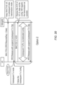
- Figure 20 illustrates an embodiment of this second option.
- the current base station may decide to cause the UE to remain in the INACTIVE state and to transition to a subsequent data transmission mode.
- the current base station may transmit an RRCRelease message with suspend, including (or indicating) a subsequent transmission configuration.
- the UE may remain in the INACTIVE state and enter a subsequent transmission mode.
- the UE may perform subsequent user data transmission/reception while remaining in the INACTIVE state. For example, the UE may transmit a MAC CE / L1 ACK to the current base station; and then engage in subsequent user data transmission and/or reception using dedicated configuration (e.g., dedicated configuration provided with the RRCRelease message). After the subsequent user data transmission and/or reception is complete, the current base station may send an RRCRelease with suspend for the subsequent transmission configuration.
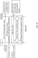
- dedicated configuration e.g., dedicated configuration provided with the RRCRelease message
- the current base station may transmit an RRCRelease message including a subsequent transmission configuration.
- the RRCRelease message may also include an explicit indication of whether or not the user data was successfully forwarded to the core network, e.g., as shown in Figure 21 .
- the UE may determine whether its user data transmission was successful based on the explicit indication. If the user data transmission was successful, the LTE may clear the corresponding user data from its buffer and proceed to transmit a next portion of user data while in the INACTIVE state. If the user data transmission was unsuccessful, the UE may attempt to retransmit the user data.
- the current base station may employ an L1/L2 command.
- Figure 22 illustrates an embodiment of this third option.
- the current base station may decide to cause the LTE to remain in the INACTIVE state and to transition to a subsequent data transmission mode.
- the message 2210 may be, e.g., a MSG3 of a random access procedure.
- the current base station may transmit message 2220 (e.g., an L1 and/or L2 message) to enable subsequent user data transmission.
- the message 2220 may be, e.g., a MSG4 of a random access procedure.
- the message 2220 may include a CR MAC CE and an indication that the LTE should enter the subsequent transmission mode while remaining in the INACTIVE state.
- CR is an acronym for Contention Resolution.
- the UE may enter the subsequent transmission mode, and perform subsequent user data transmission and/or reception using a subsequent transmit configuration, which is provided in a previous connected mode or via broadcast(s) from the network (e.g., from the current base station).
- the network may regard the transmission as a success.
- a method 2300 for operating a user equipment (UE) device may include the operations shown in Figure 23 . (The method 2300 may also include any subset of the features, elements or operations described above.) The method 2300 may be performed by processing circuity of the UE device, e.g., by the processing element 610 of user equipment 600.
- the processing circuitry may transmit information to a network, where the information includes a Radio Resource Control (RRC) message.
- RRC Radio Resource Control
- the RRC message may include an indication of the UE device's intent to perform transmission and/or reception of user data with the network during the inactive state.
- the action of transmitting the information to the network may include transmitting the information to a current base station of the network, e.g., to a current gNB in the context of 3 GPP 5GNR.
- the RRC message may be an RRC resume request message.
- the information transmitted at 2310 may include: at least a portion of the user data; and/or a buffer status report.
- the buffer status report may indicate an amount of data currently residing in an uplink transmit buffer.
- the buffer status report may be included if the amount of user data to be transmitted exceeds a threshold value.
- the information transmitted at 2310 may include identity information to enable the network to identify the UE device and/or to fetch context information associated with the UE device, e.g., as variously described above.
- the RRC message may include a cause indicator field that indicates a cause for which the RRC message is being transmitted.
- the cause indicator field may be set to a value indicating data transmission (or small data transmission) as the cause.
- the information transmitted at 2310 is (or, is part of) a Medium Access Control Protocol Data Unit (MAC PDU), e.g., as variously described above.
- a MAC PDU may include one or more sub-PDUs.
- One of the sub-PDUs (e.g., a first of the sub-PDUs) of the MAC PDU may include the RRC message.
- Another one of the sub-PDUs (e.g., a second of the sub-PDUs) may include said at least a portion of the user data.
- the method 2300 may also include, while in the inactive state, receiving a response message from the network, wherein the response message induces a state transition in the UE device.
- the response message may be a release message (e.g., an RRCRelease message), and may induce a state transition to an idle state.
- a release message e.g., an RRCRelease message
- the response message may be a release message with a suspend configuration, and may induce a state transition to a legacy inactive state.
- the response message may be a resume message, and may induce a state transition to a connected state.
- the response message may be a setup message, and may induce a state transition to a connected state.
- the response message may cause the UE device to stay in the inactive state and enter a subsequent user data transmission mode.
- the UE device may transmit and/or receive additional user data (or, an addition of portion of the user data mentioned at 2310) while remaining in the inactive state, e.g., as described above in the context of Figures 18-22 .
- the response message may implicitly indicates that forwarding of the user data to a core network was successful
- the response message may explicitly indicate whether forwarding of the user data to a core network was successful.
- a non-transitory memory medium may store program instructions.
- the program instructions when executed by processing circuitry, may cause the processing circuitry to perform the method of embodiments described above and any combination of those embodiments.
- the memory medium may incorporated as part of a user equipment device.
- a method 2400 for operating a base station may include the operations shown in Figure 24 . (The method 2400 may also include any subset of the features, elements or operations described above.) The method may be performed by processing circuity of the base station, e.g., by the processing element 710 of base station 700.
- the processing circuitry may receive information from the UE device where the information includes a Radio Resource Control (RRC) message.
- the RRC message may include an indication of the LTE device's intent to perform transmission and/or reception of user data with the network during the inactive state.
- the user data may originate from the LTE device, e.g., from an application executing on the UE device.
- the user data may originate from the network, and it to be received by the UE device.
- the RRC message may be an RRC resume request message.
- the information received at 2410 may include: at least a portion of the user data; and/or a buffer status report.
- the buffer status report may indicate an amount of data currently residing in an uplink transmit buffer of the UE device.
- the buffer status report may be included if the amount of user data to be transmitted by the UE device exceeds a threshold value.
- the information received at 2410 may include identity information to enable the network to identify the UE device and/or to fetch context information associated with the UE device, e.g., as variously described above.
- the base station may employ the identity information to request a fetch of the UE context, e.g., from a last serving base station.
- the RRC message may include a cause indicator field that indicates a cause for the RRC message.
- the cause indicator field is set to a value indicating data transmission (or small data transmission) as the cause.
- the message is (or is contained within) a Medium Access Control Protocol Data Unit (MAC PDU), e.g., as variously described above.
- MAC PDU Medium Access Control Protocol Data Unit
- the method 2400 may also include, while the UE device is in the inactive state, transmitting a response message to the UE device.
- the response message may induce a state transition in the UE device, e.g., as variously described above.
- the response message may be a release message (e.g., an RRCRelease message), and may induce a state transition to an idle state.
- a release message e.g., an RRCRelease message
- the response message may be a release message (e.g., an RRCRelease message) with a suspend configuration, and may induce a state transition to a legacy inactive state.
- a release message e.g., an RRCRelease message
- the response message may be a resume message (e.g., an RRCResume message), and may induce a state transition to a connected state.
- a resume message e.g., an RRCResume message
- the response message may be a setup message (e.g., an RRCSetup message), and may induce a state transition to a connected state.
- a setup message e.g., an RRCSetup message
- the response message may cause the UE device to stay in the inactive state and enter a subsequent user data transmission mode. While the UE device remains in the inactive state and the subsequent user data transmission mode, the base station may transmit and/or receive additional user data (or an addition portion of the user data mentioned at 2410) to/from the UE device.
- the response message may implicitly indicate that forwarding of the user data to a core network was successful, e.g., as variously described above.
- the response message may explicitly indicate whether forwarding of the user data to a core network was successful, e.g., as variously described above.
- the base station may serve as a gNB in a network according to the 3GPP SGNR standard.
- a non-transitory memory medium may store program instructions.
- the program instructions when executed by processing circuitry, may cause the processing circuitry to perform any of the method embodiments described above, and any combination of those embodiments.
- the memory medium may incorporated as part of a base station.
- Embodiments of the present disclosure may be realized in any of various forms. For example, some embodiments may be realized as a computer-implemented method, a computer-readable memory medium, or a computer system. Other embodiments may be realized using one or more custom-designed hardware devices such as ASICs. Still other embodiments may be realized using one or more programmable hardware elements such as FPGAs.
- a non-transitory computer-readable memory medium may be configured so that it stores program instructions and/or data, where the program instructions, if executed by a computer system, cause the computer system to perform a method, e.g., any of a method embodiments described herein, or, any combination of the method embodiments described herein, or, any subset of any of the method embodiments described herein, or, any combination of such subsets.
- a computer system may be configured to include a processor (or a set of processors) and a memory medium, where the memory medium stores program instructions, where the processor is configured to read and execute the program instructions from the memory medium, where the program instructions are executable to implement any of the various method embodiments described herein (or, any combination of the method embodiments described herein, or, any subset of any of the method embodiments described herein, or, any combination of such subsets).
- the computer system may be realized in any of various forms.
- the computer system may be a personal computer (in any of its various realizations), a workstation, a computer on a card, an application-specific computer in a box, a server computer, a client computer, a hand-held device, a user equipment (UE) device, a tablet computer, a wearable computer, etc.
- a personal computer in any of its various realizations
- a workstation in any of its various realizations
- a computer on a card an application-specific computer in a box
- a server computer a client computer
- a hand-held device a user equipment (UE) device
- UE user equipment
- Any of the methods described herein for operating a user equipment (UE) in communication with a base station (or transmission-reception point) may be the basis of a corresponding method for operating a base station (or transmission-reception point), by interpreting each message/signal X received by the UE in the downlink as a message/signal X transmitted by the base station (or transmission-reception point), and each message/signal Y transmitted in the uplink by the LTE as a message/signal Y received by the base station (or transmission-reception point).
- personally identifiable information should follow privacy policies and practices that are generally recognized as meeting or exceeding industry or governmental requirements for maintaining the privacy of users.
- personally identifiable information data should be managed and handled so as to minimize risks of unintentional or unauthorized access or use, and the nature of authorized use should be clearly indicated to users.
Landscapes
- Engineering & Computer Science (AREA)
- Computer Networks & Wireless Communication (AREA)
- Signal Processing (AREA)
- Mobile Radio Communication Systems (AREA)
Priority Applications (1)
| Application Number | Priority Date | Filing Date | Title |
|---|---|---|---|
| EP24205285.0A EP4465756A3 (de) | 2020-10-22 | 2020-10-22 | Rrc-basierte benutzerdatenübertragung im inaktiven zustand |
Applications Claiming Priority (3)
| Application Number | Priority Date | Filing Date | Title |
|---|---|---|---|
| EP24205285.0A EP4465756A3 (de) | 2020-10-22 | 2020-10-22 | Rrc-basierte benutzerdatenübertragung im inaktiven zustand |
| PCT/CN2020/122751 WO2022082582A1 (en) | 2020-10-22 | 2020-10-22 | Rrc-based user data transmission in inactive state |
| EP20958165.1A EP4233477A4 (de) | 2020-10-22 | 2020-10-22 | Rrc-basierte benutzerdatenübertragung im inaktiven zustand |
Related Parent Applications (1)
| Application Number | Title | Priority Date | Filing Date |
|---|---|---|---|
| EP20958165.1A Division EP4233477A4 (de) | 2020-10-22 | 2020-10-22 | Rrc-basierte benutzerdatenübertragung im inaktiven zustand |
Publications (2)
| Publication Number | Publication Date |
|---|---|
| EP4465756A2 true EP4465756A2 (de) | 2024-11-20 |
| EP4465756A3 EP4465756A3 (de) | 2025-02-26 |
Family
ID=81289602
Family Applications (2)
| Application Number | Title | Priority Date | Filing Date |
|---|---|---|---|
| EP20958165.1A Withdrawn EP4233477A4 (de) | 2020-10-22 | 2020-10-22 | Rrc-basierte benutzerdatenübertragung im inaktiven zustand |
| EP24205285.0A Pending EP4465756A3 (de) | 2020-10-22 | 2020-10-22 | Rrc-basierte benutzerdatenübertragung im inaktiven zustand |
Family Applications Before (1)
| Application Number | Title | Priority Date | Filing Date |
|---|---|---|---|
| EP20958165.1A Withdrawn EP4233477A4 (de) | 2020-10-22 | 2020-10-22 | Rrc-basierte benutzerdatenübertragung im inaktiven zustand |
Country Status (5)
| Country | Link |
|---|---|
| US (2) | US12114389B2 (de) |
| EP (2) | EP4233477A4 (de) |
| KR (2) | KR20240152405A (de) |
| CN (2) | CN116349391A (de) |
| WO (1) | WO2022082582A1 (de) |
Families Citing this family (5)
| Publication number | Priority date | Publication date | Assignee | Title |
|---|---|---|---|---|
| US12155696B2 (en) * | 2019-08-07 | 2024-11-26 | Lg Electronics Inc. | Method and apparatus for internet protocol multimedia subsystem (IMS) signaling for non-service attempt |
| KR102750792B1 (ko) * | 2020-09-22 | 2025-01-09 | 아서스테크 컴퓨터 인코포레이션 | 무선 통신 시스템에서 스몰 데이터 전송의 새로운 데이터 도착을 위한 방법 및 장치 |
| WO2022200033A1 (en) * | 2021-03-26 | 2022-09-29 | Nokia Technologies Oy | Data transmission in inactive state connection |
| US12538349B2 (en) * | 2021-04-01 | 2026-01-27 | Google Llc | Managing data communication before and after a state transition |
| US12495392B2 (en) * | 2022-11-03 | 2025-12-09 | T-Mobile Usa, Inc. | Paging message for mobile terminating small data transmission |
Family Cites Families (19)
| Publication number | Priority date | Publication date | Assignee | Title |
|---|---|---|---|---|
| US10356837B2 (en) * | 2016-09-29 | 2019-07-16 | Acer Incorporated | State transitioning method and electronic device using the same |
| KR102310719B1 (ko) * | 2017-03-20 | 2021-10-08 | 삼성전자 주식회사 | 차세대 이동통신에서 대기 모드 동작을 효과적으로 하는 방법 및 장치 |
| US10856163B2 (en) | 2017-07-07 | 2020-12-01 | Lg Electronics Inc. | Method for performing measurement and device supporting the same |
| US10855359B2 (en) * | 2017-08-10 | 2020-12-01 | Comcast Cable Communications, Llc | Priority of beam failure recovery request and uplink channels |
| CN110351744B (zh) | 2018-04-04 | 2021-02-09 | 华为技术有限公司 | 通信方法、网络设备和通信设备 |
| PL3791687T3 (pl) | 2018-05-10 | 2023-12-27 | Telefonaktiebolaget Lm Ericsson (Publ) | Przyczyna zwolnienia dla przejścia ze stanu połączonego |
| EP3876642B1 (de) * | 2018-05-21 | 2025-09-17 | Comcast Cable Communications LLC | Direktzugriffsverfahren unter verwendung mehrerer aktiver bandbreitenteile |
| EP3609289A1 (de) | 2018-08-10 | 2020-02-12 | Nokia Technologies Oy | Kombiniertes rrc-inaktives resume, rrc rna- und nas-registrierungsprozedur |
| ES2888407T3 (es) * | 2018-09-25 | 2022-01-04 | Ericsson Telefon Ab L M | Solicitud de reanudación seguida por liberación y redirección |
| US11432239B2 (en) | 2018-10-18 | 2022-08-30 | Apple Inc. | Inactive mode operations |
| US11882541B2 (en) * | 2019-01-11 | 2024-01-23 | Apple Inc. | Systems and methods of providing new radio positioning |
| WO2020167182A1 (en) * | 2019-02-12 | 2020-08-20 | Telefonaktiebolaget Lm Ericsson (Publ) | Early measurement reporting with rrc resume complete like message |
| WO2020167205A1 (en) * | 2019-02-12 | 2020-08-20 | Telefonaktiebolaget Lm Ericsson (Publ) | Early measurement reporting with rrc resume request message and indication of request for early measurements in association with paging |
| KR102854552B1 (ko) * | 2019-02-13 | 2025-09-02 | 삼성전자주식회사 | 무선 통신 시스템에서 캐리어 어그리게이션을 지원하기 위한 방법 및 장치 |
| US11895720B2 (en) * | 2019-02-14 | 2024-02-06 | Nokia Technologies Oy | Control mechanism for supporting connection establishment procedure |
| EP3925305B1 (de) * | 2019-02-14 | 2023-11-29 | Telefonaktiebolaget LM Ericsson (publ) | Steuerung der meldung von frühmessungen und verbundenen modusmessungen auf basis von verkehrsvolumen und anderen bedingungen |
| JP7481820B2 (ja) * | 2019-09-27 | 2024-05-13 | Kddi株式会社 | ランダムアクセス手順を実行する端末装置、基地局装置、制御方法、及びプログラム |
| US20220086946A1 (en) * | 2020-09-17 | 2022-03-17 | Asustek Computer Inc. | Method and apparatus for small data transmission in a wireless communication system |
| WO2022067771A1 (zh) * | 2020-09-30 | 2022-04-07 | Oppo广东移动通信有限公司 | 数据传输方法和终端设备 |
-
2020
- 2020-10-22 KR KR1020247033185A patent/KR20240152405A/ko active Pending
- 2020-10-22 CN CN202080106521.9A patent/CN116349391A/zh active Pending
- 2020-10-22 KR KR1020237013179A patent/KR20230070273A/ko active Pending
- 2020-10-22 US US17/438,196 patent/US12114389B2/en active Active
- 2020-10-22 EP EP20958165.1A patent/EP4233477A4/de not_active Withdrawn
- 2020-10-22 CN CN202411390510.4A patent/CN119342628A/zh active Pending
- 2020-10-22 WO PCT/CN2020/122751 patent/WO2022082582A1/en not_active Ceased
- 2020-10-22 EP EP24205285.0A patent/EP4465756A3/de active Pending
-
2024
- 2024-10-01 US US18/903,932 patent/US20250024551A1/en active Pending
Also Published As
| Publication number | Publication date |
|---|---|
| US12114389B2 (en) | 2024-10-08 |
| EP4233477A1 (de) | 2023-08-30 |
| EP4465756A3 (de) | 2025-02-26 |
| EP4233477A4 (de) | 2024-07-17 |
| KR20240152405A (ko) | 2024-10-21 |
| US20250024551A1 (en) | 2025-01-16 |
| US20220322482A1 (en) | 2022-10-06 |
| WO2022082582A1 (en) | 2022-04-28 |
| KR20230070273A (ko) | 2023-05-22 |
| CN116349391A (zh) | 2023-06-27 |
| CN119342628A (zh) | 2025-01-21 |
Similar Documents
| Publication | Publication Date | Title |
|---|---|---|
| US11528679B2 (en) | 5G new radio de-registration procedures | |
| US20200260498A1 (en) | 2-Step Random Access | |
| US20250024551A1 (en) | RRC-Based User Data Transmission in an Inactive State | |
| US20250071809A1 (en) | Non-SDT DRB Handling | |
| US12512939B2 (en) | Dynamic configuration of aperiodic sounding reference signal offsets in cellular communications systems | |
| US11265925B2 (en) | Downlink radio resource control message transmission in 2-step random access | |
| US12490260B2 (en) | Retransmission of MsgB in two-step random access procedure | |
| US12309847B2 (en) | Downlink radio resource control message transmission in 2-step random access | |
| US20250039907A1 (en) | Techniques in Multicast and Broadband Services (MBS) HARQ Feedback | |
| US12520381B2 (en) | Techniques for emergency service fall back error handling |
Legal Events
| Date | Code | Title | Description |
|---|---|---|---|
| PUAI | Public reference made under article 153(3) epc to a published international application that has entered the european phase |
Free format text: ORIGINAL CODE: 0009012 |
|
| STAA | Information on the status of an ep patent application or granted ep patent |
Free format text: STATUS: REQUEST FOR EXAMINATION WAS MADE |
|
| 17P | Request for examination filed |
Effective date: 20241008 |
|
| AC | Divisional application: reference to earlier application |
Ref document number: 4233477 Country of ref document: EP Kind code of ref document: P |
|
| AK | Designated contracting states |
Kind code of ref document: A2 Designated state(s): AL AT BE BG CH CY CZ DE DK EE ES FI FR GB GR HR HU IE IS IT LI LT LU LV MC MK MT NL NO PL PT RO RS SE SI SK SM TR |
|
| RIN1 | Information on inventor provided before grant (corrected) |
Inventor name: VANGALA, SARMA V. Inventor name: JIA, ZHANFENG Inventor name: NIMMALA,SRINIVASAN Inventor name: HU,HAIJING Inventor name: ZHANG, DAWEI Inventor name: SHIKARI, MURTAZA A. Inventor name: ROSSBACH, RALF Inventor name: XU, FANGLI |
|
| PUAL | Search report despatched |
Free format text: ORIGINAL CODE: 0009013 |
|
| AK | Designated contracting states |
Kind code of ref document: A3 Designated state(s): AL AT BE BG CH CY CZ DE DK EE ES FI FR GB GR HR HU IE IS IT LI LT LU LV MC MK MT NL NO PL PT RO RS SE SI SK SM TR |
|
| RIC1 | Information provided on ipc code assigned before grant |
Ipc: H04W 76/27 20180101AFI20250120BHEP |