EP4465636A1 - Punktwolkendatenübertragungsverfahren, punktwolkendatenübertragungsvorrichtung, punktwolkendatenempfangsverfahren und punktwolkendatenempfangsvorrichtung - Google Patents
Punktwolkendatenübertragungsverfahren, punktwolkendatenübertragungsvorrichtung, punktwolkendatenempfangsverfahren und punktwolkendatenempfangsvorrichtung Download PDFInfo
- Publication number
- EP4465636A1 EP4465636A1 EP23740462.9A EP23740462A EP4465636A1 EP 4465636 A1 EP4465636 A1 EP 4465636A1 EP 23740462 A EP23740462 A EP 23740462A EP 4465636 A1 EP4465636 A1 EP 4465636A1
- Authority
- EP
- European Patent Office
- Prior art keywords
- point cloud
- subgroup
- layer
- cloud data
- node
- Prior art date
- Legal status (The legal status is an assumption and is not a legal conclusion. Google has not performed a legal analysis and makes no representation as to the accuracy of the status listed.)
- Pending
Links
Images


Classifications
-
- H—ELECTRICITY
- H04—ELECTRIC COMMUNICATION TECHNIQUE
- H04N—PICTORIAL COMMUNICATION, e.g. TELEVISION
- H04N19/00—Methods or arrangements for coding, decoding, compressing or decompressing digital video signals
- H04N19/90—Methods or arrangements for coding, decoding, compressing or decompressing digital video signals using coding techniques not provided for in groups H04N19/10-H04N19/85, e.g. fractals
- H04N19/96—Tree coding, e.g. quad-tree coding
-
- G—PHYSICS
- G06—COMPUTING OR CALCULATING; COUNTING
- G06T—IMAGE DATA PROCESSING OR GENERATION, IN GENERAL
- G06T9/00—Image coding
- G06T9/001—Model-based coding, e.g. wire frame
-
- G—PHYSICS
- G06—COMPUTING OR CALCULATING; COUNTING
- G06T—IMAGE DATA PROCESSING OR GENERATION, IN GENERAL
- G06T9/00—Image coding
- G06T9/40—Tree coding, e.g. quadtree, octree
-
- G—PHYSICS
- G06—COMPUTING OR CALCULATING; COUNTING
- G06V—IMAGE OR VIDEO RECOGNITION OR UNDERSTANDING
- G06V10/00—Arrangements for image or video recognition or understanding
- G06V10/20—Image preprocessing
- G06V10/25—Determination of region of interest [ROI] or a volume of interest [VOI]
-
- H—ELECTRICITY
- H04—ELECTRIC COMMUNICATION TECHNIQUE
- H04N—PICTORIAL COMMUNICATION, e.g. TELEVISION
- H04N19/00—Methods or arrangements for coding, decoding, compressing or decompressing digital video signals
- H04N19/10—Methods or arrangements for coding, decoding, compressing or decompressing digital video signals using adaptive coding
- H04N19/134—Methods or arrangements for coding, decoding, compressing or decompressing digital video signals using adaptive coding characterised by the element, parameter or criterion affecting or controlling the adaptive coding
- H04N19/167—Position within a video image, e.g. region of interest [ROI]
-
- H—ELECTRICITY
- H04—ELECTRIC COMMUNICATION TECHNIQUE
- H04N—PICTORIAL COMMUNICATION, e.g. TELEVISION
- H04N19/00—Methods or arrangements for coding, decoding, compressing or decompressing digital video signals
- H04N19/46—Embedding additional information in the video signal during the compression process
- H04N19/463—Embedding additional information in the video signal during the compression process by compressing encoding parameters before transmission
-
- H—ELECTRICITY
- H04—ELECTRIC COMMUNICATION TECHNIQUE
- H04N—PICTORIAL COMMUNICATION, e.g. TELEVISION
- H04N19/00—Methods or arrangements for coding, decoding, compressing or decompressing digital video signals
- H04N19/50—Methods or arrangements for coding, decoding, compressing or decompressing digital video signals using predictive coding
- H04N19/597—Methods or arrangements for coding, decoding, compressing or decompressing digital video signals using predictive coding specially adapted for multi-view video sequence encoding
-
- H—ELECTRICITY
- H04—ELECTRIC COMMUNICATION TECHNIQUE
- H04N—PICTORIAL COMMUNICATION, e.g. TELEVISION
- H04N19/00—Methods or arrangements for coding, decoding, compressing or decompressing digital video signals
- H04N19/70—Methods or arrangements for coding, decoding, compressing or decompressing digital video signals characterised by syntax aspects related to video coding, e.g. related to compression standards
Definitions
- Embodiments relate to a method and device for processing point cloud content.
- Point cloud content is content represented by a point cloud, which is a set of points belonging to a coordinate system representing a three-dimensional space.
- the point cloud content may express media configured in three dimensions, and is used to provide various services such as virtual reality (VR), augmented reality (AR), mixed reality (MR), and self-driving services.
- VR virtual reality
- AR augmented reality
- MR mixed reality
- self-driving services tens of thousands to hundreds of thousands of point data are required to represent point cloud content. Therefore, there is a need for a method for efficiently processing a large amount of point data.
- Embodiments provide a device and method for efficiently processing point cloud data.
- Embodiments provide a point cloud data processing method and device for addressing latency and encoding/decoding complexity.
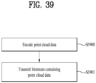
- a method of transmitting point cloud data may include encoding point cloud data, and transmitting a bitstream containing the point cloud data.
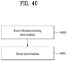
- a method of receiving point cloud data may include receiving a bitstream containing point cloud data, and decoding the point cloud data.
- Devices and methods according to embodiments may process point cloud data with high efficiency.
- the devices and methods according to the embodiments may provide a high-quality point cloud service.
- the devices and methods according to the embodiments may provide point cloud content for providing general-purpose services such as a VR service and a self-driving service.
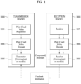
- FIG. 1 shows an exemplary point cloud content providing system according to embodiments.
- the point cloud content providing system illustrated in FIG. 1 may include a transmission device 10000 and a reception device 10004.
- the transmission device 10000 and the reception device 10004 are capable of wired or wireless communication to transmit and receive point cloud data.
- the point cloud data transmission device 10000 may secure and process point cloud video (or point cloud content) and transmit the same.
- the transmission device 10000 may include a fixed station, a base transceiver system (BTS), a network, an artificial intelligence (AI) device and/or system, a robot, an AR/VR/XR device and/or server.
- BTS base transceiver system
- AI artificial intelligence
- the transmission device 10000 may include a device, a robot, a vehicle, an AR/VR/XR device, a portable device, a home appliance, an Internet of Thing (IoT) device, and an AI device/server which are configured to perform communication with a base station and/or other wireless devices using a radio access technology (e.g., 5G New RAT (NR), Long Term Evolution (LTE)).
- a radio access technology e.g., 5G New RAT (NR), Long Term Evolution (LTE)
- the transmission device 10000 includes a point cloud video acquirer 10001, a point cloud video encoder 10002, and/or a transmitter (or communication module) 10003.
- the point cloud video acquirer 10001 acquires a point cloud video through a processing process such as capture, synthesis, or generation.
- the point cloud video is point cloud content represented by a point cloud, which is a set of points positioned in a 3D space, and may be referred to as point cloud video data, point cloud data, or the like.
- the point cloud video according to the embodiments may include one or more frames. One frame represents a still image/picture. Therefore, the point cloud video may include a point cloud image/frame/picture, and may be referred to as a point cloud image, frame, or picture.
- the transmitter 10003 transmits the bitstream containing the encoded point cloud video data.
- the bitstream according to the embodiments is encapsulated in a file or segment (e.g., a streaming segment), and is transmitted over various networks such as a broadcasting network and/or a broadband network.
- the transmission device 10000 may include an encapsulator (or an encapsulation module) configured to perform an encapsulation operation.
- the encapsulator may be included in the transmitter 10003.
- the file or segment may be transmitted to the reception device 10004 over a network, or stored in a digital storage medium (e.g., USB, SD, CD, DVD, Blu-ray, HDD, SSD, etc.).
- the transmitter 10003 is capable of wired/wireless communication with the reception device 10004 (or the receiver 10005) over a network of 4G, 5G, 6G, etc.
- the transmitter may perform a necessary data processing operation according to the network system (e.g., a 4G, 5G or 6G communication network system).
- the transmission device 10000 may transmit the encapsulated data in an on-demand manner.
- the reception device 10004 includes a receiver 10005, a point cloud video decoder 10006, and/or a renderer 10007.
- the reception device 10004 may include a device, a robot, a vehicle, an AR/VR/XR device, a portable device, a home appliance, an Internet of Things (IoT) device, and an AI device/server which are configured to perform communication with a base station and/or other wireless devices using a radio access technology (e.g., 5G New RAT (NR), Long Term Evolution (LTE)).
- a radio access technology e.g., 5G New RAT (NR), Long Term Evolution (LTE)
- the receiver 10005 receives the bitstream containing the point cloud video data or the file/segment in which the bitstream is encapsulated from the network or storage medium.
- the receiver 10005 may perform necessary data processing according to the network system (e.g., a communication network system of 4G, 5G, 6G, etc.).
- the receiver 10005 according to the embodiments may decapsulate the received file/segment and output a bitstream.
- the receiver 10005 may include a decapsulator (or a decapsulation module) configured to perform a decapsulation operation.
- the decapsulator may be implemented as an element (or component) separate from the receiver 10005.
- the point cloud video decoder 10006 decodes the bitstream containing the point cloud video data.
- the point cloud video decoder 10006 may decode the point cloud video data according to the method by which the point cloud video data is encoded (e.g., in a reverse process of the operation of the point cloud video encoder 10002). Accordingly, the point cloud video decoder 10006 may decode the point cloud video data by performing point cloud decompression coding, which is the reverse process to the point cloud compression.
- the point cloud decompression coding includes G-PCC coding.
- the renderer 10007 renders the decoded point cloud video data.
- the renderer 10007 may output point cloud content by rendering not only the point cloud video data but also audio data.
- the renderer 10007 may include a display configured to display the point cloud content.
- the display may be implemented as a separate device or component rather than being included in the renderer 10007.
- the arrows indicated by dotted lines in the drawing represent a transmission path of feedback information acquired by the reception device 10004.
- the feedback information is information for reflecting interactivity with a user who consumes the point cloud content, and includes information about the user (e.g., head orientation information, viewport information, and the like).
- the feedback information may be provided to the content transmitting side (e.g., the transmission device 10000) and/or the service provider.
- the feedback information may be used in the reception device 10004 as well as the transmission device 10000, or may not be provided.
- the head orientation information is information about the user's head position, orientation, angle, motion, and the like.
- the reception device 10004 may calculate the viewport information based on the head orientation information.
- the viewport information may be information about a region of a point cloud video that the user is viewing.
- a viewpoint is a point through which the user is viewing the point cloud video, and may refer to a center point of the viewport region. That is, the viewport is a region centered on the viewpoint, and the size and shape of the region may be determined by a field of view (FOV).
- FOV field of view
- the reception device 10004 may extract the viewport information based on a vertical or horizontal FOV supported by the device in addition to the head orientation information.
- the reception device 10004 performs gaze analysis or the like to check the way the user consumes a point cloud, a region that the user gazes at in the point cloud video, a gaze time, and the like.
- the reception device 10004 may transmit feedback information including the result of the gaze analysis to the transmission device 10000.
- the feedback information according to the embodiments may be acquired in the rendering and/or display process.
- the feedback information according to the embodiments may be secured by one or more sensors included in the reception device 10004.
- the feedback information may be secured by the renderer 10007 or a separate external element (or device, component, or the like).
- the dotted lines in FIG. 1 represent a process of transmitting the feedback information secured by the renderer 10007.
- the point cloud content providing system may process (encode/decode) point cloud data based on the feedback information. Accordingly, the point cloud video data decoder 10006 may perform a decoding operation based on the feedback information.
- the reception device 10004 may transmit the feedback information to the transmission device 10000.
- the transmission device 10000 (or the point cloud video data encoder 10002) may perform an encoding operation based on the feedback information. Accordingly, the point cloud content providing system may efficiently process necessary data (e.g., point cloud data corresponding to the user's head position) based on the feedback information rather than processing (encoding/decoding) the entire point cloud data, and provide point cloud content to the user.
- the transmission device 10000 may be called an encoder, a transmission device, a transmitter, or the like, and the reception device 10004 may be called a decoder, a receiving device, a receiver, or the like.
- the point cloud data processed in the point cloud content providing system of FIG. 1 may be referred to as point cloud content data or point cloud video data.
- the point cloud content data may be used as a concept covering metadata or signaling information related to the point cloud data.
- the elements of the point cloud content providing system illustrated in FIG. 1 may be implemented by hardware, software, a processor, and/or a combination thereof.
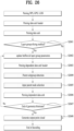
- FIG. 2 is a block diagram illustrating a point cloud content providing operation according to embodiments.
- the block diagram of FIG. 2 shows the operation of the point cloud content providing system described in FIG. 1 .
- the point cloud content providing system may process point cloud data based on point cloud compression coding (e.g., G-PCC).
- point cloud compression coding e.g., G-PCC
- the point cloud content providing system may acquire a point cloud video (20000).
- the point cloud video is represented by a point cloud belonging to a coordinate system for expressing a 3D space.
- the point cloud video according to the embodiments may include a Ply (Polygon File format or the Stanford Triangle format) file.
- the acquired point cloud video may include one or more Ply files.
- the Ply files contain point cloud data, such as point geometry and/or attributes.
- the geometry includes positions of points.
- the position of each point may be represented by parameters (e.g., values of the X, Y, and Z axes) representing a three-dimensional coordinate system (e.g., a coordinate system composed of X, Y and Z axes).
- the attributes include attributes of points (e.g., information about texture, color (in YCbCr or RGB), reflectance r, transparency, etc. of each point).
- a point has one or more attributes.
- a point may have an attribute that is a color, or two attributes that are color and reflectance.
- the geometry may be called positions, geometry information, geometry data, position information, position data, or the like, and the attribute may be called attributes, attribute information, attribute data, or the like.
- the point cloud content providing system e.g., the point cloud transmission device 10000 or the point cloud video acquirer 10001
- the point cloud content providing system may encode the point cloud data (20001).
- the point cloud content providing system may encode the point cloud data based on point cloud compression coding.
- the point cloud data may include the geometry information and attribute information about a point.
- the point cloud content providing system may perform geometry encoding of encoding the geometry and output a geometry bitstream.
- the point cloud content providing system may perform attribute encoding of encoding attributes and output an attribute bitstream.
- the point cloud content providing system may perform the attribute encoding based on the geometry encoding.
- the geometry bitstream and the attribute bitstream according to the embodiments may be multiplexed and output as one bitstream.
- the bitstream according to the embodiments may further contain signaling information related to the geometry encoding and attribute encoding.
- the point cloud content providing system may transmit the encoded point cloud data (20002).
- the encoded point cloud data may be represented by a geometry bitstream and an attribute bitstream.
- the encoded point cloud data may be transmitted in the form of a bitstream together with signaling information related to encoding of the point cloud data (e.g., signaling information related to the geometry encoding and the attribute encoding).
- the point cloud content providing system may encapsulate a bitstream that carries the encoded point cloud data and transmit the same in the form of a file or segment.
- the point cloud content providing system may receive the bitstream containing the encoded point cloud data.
- the point cloud content providing system e.g., the reception device 10004 or the receiver 10005 may demultiplex the bitstream.
- the point cloud content providing system may decode the encoded point cloud data (e.g., the geometry bitstream, the attribute bitstream) transmitted in the bitstream.
- the point cloud content providing system e.g., the reception device 10004 or the point cloud video decoder 10005) may decode the point cloud video data based on the signaling information related to encoding of the point cloud video data contained in the bitstream.
- the point cloud content providing system e.g., the reception device 10004 or the point cloud video decoder 10005
- the point cloud content providing system may reconstruct the attributes of the points by decoding the attribute bitstream based on the reconstructed geometry.
- the point cloud content providing system (e.g., the reception device 10004 or the point cloud video decoder 10005) may reconstruct the point cloud video based on the positions according to the reconstructed geometry and the decoded attributes.
- the point cloud content providing system may render the decoded point cloud data (20004).
- the point cloud content providing system e.g., the reception device 10004 or the renderer 10007) may render the geometry and attributes decoded through the decoding process, using various rendering methods. Points in the point cloud content may be rendered to a vertex having a certain thickness, a cube having a specific minimum size centered on the corresponding vertex position, or a circle centered on the corresponding vertex position. All or part of the rendered point cloud content is provided to the user through a display (e.g., a VRjAR display, a general display, etc.).
- a display e.g., a VRjAR display, a general display, etc.
- the point cloud content providing system (e.g., the reception device 10004) according to the embodiments may secure feedback information (20005).
- the point cloud content providing system may encode and/or decode point cloud data based on the feedback information.
- the feedback information and the operation of the point cloud content providing system according to the embodiments are the same as the feedback information and the operation described with reference to FIG. 1 , and thus detailed description thereof is omitted.
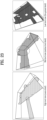
- FIG. 3 illustrates an exemplary process of capturing a point cloud video according to embodiments.
- FIG. 3 illustrates an exemplary point cloud video capture process of the point cloud content providing system described with reference to FIGS. 1 to 2 .
- Point cloud content includes a point cloud video (images and/or videos) representing an object and/or environment located in various 3D spaces (e.g., a 3D space representing a real environment, a 3D space representing a virtual environment, etc.).
- the point cloud content providing system may capture a point cloud video using one or more cameras (e.g., an infrared camera capable of securing depth information, an RGB camera capable of extracting color information corresponding to the depth information, etc.), a projector (e.g., an infrared pattern projector to secure depth information), a LiDAR, or the like.
- the point cloud content providing system may extract the shape of geometry composed of points in a 3D space from the depth information and extract the attributes of each point from the color information to secure point cloud data.
- An image and/or video according to the embodiments may be captured based on at least one of the inward-facing technique and the outward-facing technique.
- the left part of FIG. 3 illustrates the inward-facing technique.
- the inward-facing technique refers to a technique of capturing images a central object with one or more cameras (or camera sensors) positioned around the central object.
- the inward-facing technique may be used to generate point cloud content providing a 360-degree image of a key object to the user (e.g., VRjAR content providing a 360-degree image of an object (e.g., a key object such as a character, player, object, or actor) to the user).
- VRjAR content providing a 360-degree image of an object (e.g., a key object such as a character, player, object, or actor) to the user).
- the right part of FIG. 3 illustrates the outward-facing technique.
- the outward-facing technique refers to a technique of capturing images an environment of a central object rather than the central object with one or more cameras (or camera sensors) positioned around the central object.
- the outward-facing technique may be used to generate point cloud content for providing a surrounding environment that appears from the user's point of view (e.g., content representing an external environment that may be provided to a user of a self-driving vehicle).
- the point cloud content may be generated based on the capturing operation of one or more cameras.
- the coordinate system may differ among the cameras, and accordingly the point cloud content providing system may calibrate one or more cameras to set a global coordinate system before the capturing operation.
- the point cloud content providing system may generate point cloud content by synthesizing an arbitrary image and/or video with an image and/or video captured by the above-described capture technique.
- the point cloud content providing system may not perform the capturing operation described in FIG. 3 when it generates point cloud content representing a virtual space.
- the point cloud content providing system according to the embodiments may perform post-processing on the captured image and/or video. In other words, the point cloud content providing system may remove an unwanted area (e.g., a background), recognize a space to which the captured images and/or videos are connected, and, when there is a spatial hole, perform an operation of filling the spatial hole.
- an unwanted area e.g., a background
- the point cloud content providing system may generate one piece of point cloud content by performing coordinate transformation on points of the point cloud video secured from each camera.
- the point cloud content providing system may perform coordinate transformation on the points based on the coordinates of the position of each camera. Accordingly, the point cloud content providing system may generate content representing one wide range, or may generate point cloud content having a high density of points.
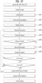
- FIG. 4 illustrates an exemplary point cloud encoder according to embodiments.
- FIG. 4 shows an example of the point cloud video encoder 10002 of FIG. 1 .
- the point cloud encoder reconstructs and encodes point cloud data (e.g., positions and/or attributes of the points) to adjust the quality of the point cloud content (to, for example, lossless, lossy, or near-lossless) according to the network condition or applications.
- point cloud data e.g., positions and/or attributes of the points
- the point cloud content providing system may fail to stream the content in real time. Accordingly, the point cloud content providing system may reconstruct the point cloud content based on the maximum target bitrate to provide the same in accordance with the network environment or the like.
- the point cloud encoder may perform geometry encoding and attribute encoding.
- the geometry encoding is performed before the attribute encoding.
- the point cloud encoder includes a coordinate transformer (Transform coordinates) 40000, a quantizer (Quantize and remove points (voxelize)) 40001, an octree analyzer (Analyze octree) 40002, and a surface approximation analyzer (Analyze surface approximation) 40003, an arithmetic encoder (Arithmetic encode) 40004, a geometry reconstructor (Reconstruct geometry) 40005, a color transformer (Transform colors) 40006, an attribute transformer (Transform attributes) 40007, a RAHT transformer (RAHT) 40008, an LOD generator (Generate LOD) 40009, a lifting transformer (Lifting) 40010, a coefficient quantizer (Quantize coefficients) 40011, and/or an arithmetic encoder (Arithmetic encode) 40012.
- the coordinate transformer 40000, the quantizer 40001, the octree analyzer 40002, the surface approximation analyzer 40003, the arithmetic encoder 40004, and the geometry reconstructor 40005 may perform geometry encoding.
- the geometry encoding according to the embodiments may include octree geometry coding, predictive tree geometry coding, direct coding, trisoup geometry encoding, and entropy encoding.
- the direct coding and trisoup geometry encoding are applied selectively or in combination.
- the geometry encoding is not limited to the above-described example.
- the coordinate transformer 40000 receives positions and transforms the same into coordinates.
- the positions may be transformed into position information in a three-dimensional space (e.g., a three-dimensional space represented by an XYZ coordinate system).
- the position information in the three-dimensional space according to the embodiments may be referred to as geometry information.
- the quantizer 40001 quantizes the geometry. For example, the quantizer 40001 may quantize the points based on a minimum position value of all points (e.g., a minimum value on each of the X, Y, and Z axes). The quantizer 40001 performs a quantization operation of multiplying the difference between the minimum position value and the position value of each point by a preset quantization scale value and then finding the nearest integer value by rounding the value obtained through the multiplication. Thus, one or more points may have the same quantized position (or position value). The quantizer 40001 according to the embodiments performs voxelization based on the quantized positions to reconstruct quantized points.
- a minimum position value of all points e.g., a minimum value on each of the X, Y, and Z axes.
- the quantizer 40001 performs a quantization operation of multiplying the difference between the minimum position value and the position value of each point by a preset quantization scale value and then finding the nearest integer value by rounding the value
- points of point cloud content may be included in one or more voxels.
- the quantizer 40001 may match groups of points in the 3D space with voxels.
- one voxel may include only one point.
- one voxel may include one or more points.
- the position of the center of a voxel may be set based on the positions of one or more points included in the voxel. In this case, attributes of all positions included in one voxel may be combined and assigned to the voxel.
- the octree analyzer 40002 performs octree geometry coding (or octree coding) to present voxels in an octree structure.
- the octree structure represents points matched with voxels, based on the octal tree structure.
- the surface approximation analyzer 40003 may analyze and approximate the octree.
- the octree analysis and approximation according to the embodiments is a process of analyzing a region containing a plurality of points to efficiently provide octree and voxelization.
- the arithmetic encoder 40004 performs entropy encoding on the octree and/or the approximated octree.
- the encoding scheme includes arithmetic encoding.
- a geometry bitstream is generated.
- the color transformer 40006, the attribute transformer 40007, the RAHT transformer 40008, the LOD generator 40009, the lifting transformer 40010, the coefficient quantizer 40011, and/or the arithmetic encoder 40012 perform attribute encoding.
- one point may have one or more attributes.
- the attribute encoding according to the embodiments is equally applied to the attributes that one point has. However, when an attribute (e.g., color) includes one or more elements, attribute encoding is independently applied to each element.
- the attribute encoding according to the embodiments includes color transform coding, attribute transform coding, region adaptive hierarchical transform (RAHT) coding, interpolation-based hierarchical nearest-neighbor prediction (prediction transform) coding, and interpolation-based hierarchical nearest-neighbor prediction with an update/lifting step (lifting transform) coding.
- RAHT region adaptive hierarchical transform
- prediction transform interpolation-based hierarchical nearest-neighbor prediction
- lifting transform with an update/lifting step
- the attribute encoding according to the embodiments is not limited to the above-described example.
- the color transformer 40006 performs color transform coding of transforming color values (or textures) included in the attributes.
- the color transformer 40006 may transform the format of color information (for example, from RGB to YCbCr).
- the operation of the color transformer 40006 according to embodiments may be optionally applied according to the color values included in the attributes.
- the geometry reconstructor 40005 reconstructs (decompresses) the octree and/or the approximated octree.
- the geometry reconstructor 40005 reconstructs the octree/voxels based on the result of analyzing the distribution of points.
- the reconstructed octree/voxels may be referred to as reconstructed geometry (restored geometry).
- the attribute transformer 40007 performs attribute transformation to transform the attributes based on the reconstructed geometry and/or the positions on which geometry encoding is not performed. As described above, since the attributes are dependent on the geometry, the attribute transformer 40007 may transform the attributes based on the reconstructed geometry information. For example, based on the position value of a point included in a voxel, the attribute transformer 40007 may transform the attribute of the point at the position. As described above, when the position of the center of a voxel is set based on the positions of one or more points included in the voxel, the attribute transformer 40007 transforms the attributes of the one or more points. When the trisoup geometry encoding is performed, the attribute transformer 40007 may transform the attributes based on the trisoup geometry encoding.
- the attribute transformer 40007 may perform the attribute transformation by calculating the average of attributes or attribute values of neighboring points (e.g., color or reflectance of each point) within a specific position/radius from the position (or position value) of the center of each voxel.
- the attribute transformer 40007 may apply a weight according to the distance from the center to each point in calculating the average. Accordingly, each voxel has a position and a calculated attribute (or attribute value).
- the attribute transformer 40007 may search for neighboring points existing within a specific position/radius from the position of the center of each voxel based on the K-D tree or the Morton code.
- the K-D tree is a binary search tree and supports a data structure capable of managing points based on the positions such that nearest neighbor search (NNS) can be performed quickly.
- the Morton code is generated by presenting coordinates (e.g., (x, y, z)) representing 3D positions of all points as bit values and mixing the bits. For example, when the coordinates representing the position of a point are (5, 9, 1), the bit values for the coordinates are (0101, 1001, 0001).
- the attribute transformer 40007 may order the points based on the Morton code values and perform NNS through a depth-first traversal process. After the attribute transformation operation, the K-D tree or the Morton code is used when the NNS is needed in another transformation process for attribute coding.
- the transformed attributes are input to the RAHT transformer 40008 and/or the LOD generator 40009.
- the RAHT transformer 40008 performs RAHT coding for predicting attribute information based on the reconstructed geometry information. For example, the RAHT transformer 40008 may predict attribute information of a node at a higher level in the octree based on the attribute information associated with a node at a lower level in the octree.
- the LOD generator 40009 generates a level of detail (LOD) to perform prediction transform coding.
- LOD level of detail
- the LOD according to the embodiments is a degree of detail of point cloud content. As the LOD value decrease, it indicates that the detail of the point cloud content is degraded. As the LOD value increases, it indicates that the detail of the point cloud content is enhanced. Points may be classified by the LOD.
- the lifting transformer 40010 performs lifting transform coding of transforming the attributes a point cloud based on weights. As described above, lifting transform coding may be optionally applied.
- the coefficient quantizer 40011 quantizes the attribute-coded attributes based on coefficients.
- the arithmetic encoder 40012 encodes the quantized attributes based on arithmetic coding.
- the elements of the point cloud encoder of FIG. 4 may be implemented by hardware including one or more processors or integrated circuits configured to communicate with one or more memories included in the point cloud providing device, software, firmware, or a combination thereof.
- the one or more processors may perform at least one of the operations and/or functions of the elements of the point cloud encoder of FIG. 4 described above. Additionally, the one or more processors may operate or execute a set of software programs and/or instructions for performing the operations and/or functions of the elements of the point cloud encoder of FIG. 4 .
- the one or more memories according to the embodiments may include a high speed random access memory, or include a non-volatile memory (e.g., one or more magnetic disk storage devices, flash memory devices, or other non-volatile solid-state memory devices).
- FIG. 5 shows an example of voxels according to embodiments.
- FIG. 5 shows voxels positioned in a 3D space represented by a coordinate system composed of three axes, which are the X-axis, the Y-axis, and the Z-axis.
- the point cloud encoder e.g., the quantizer 40001
- FIG. 5 shows an example of voxels generated through an octree structure in which a cubical axis-aligned bounding box defined by two poles (0, 0, 0) and (2d, 2d, 2d) is recursively subdivided.
- One voxel includes at least one point.
- the spatial coordinates of a voxel may be estimated from the positional relationship with a voxel group.
- a voxel has an attribute (such as color or reflectance) like pixels of a 2D image/video.
- the details of the voxel are the same as those described with reference to FIG. 4 , and therefore a description thereof is omitted.
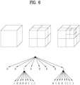
- FIG. 6 shows an example of an octree and occupancy code according to embodiments.
- the point cloud content providing system (point cloud video encoder 10002) or the point cloud encoder (e.g., the octree analyzer 40002) performs octree geometry coding (or octree coding) based on an octree structure to efficiently manage the region and/or position of the voxel.
- FIG. 6 shows an octree structure.
- the 3D space of the point cloud content according to the embodiments is represented by axes (e.g., X-axis, Y-axis, and Z-axis) of the coordinate system.
- the octree structure is created by recursive subdividing of a cubical axis-aligned bounding box defined by two poles (0, 0, 0) and (2 d , 2 d , 2 d ).
- 2 d may be set to a value constituting the smallest bounding box surrounding all points of the point cloud content (or point cloud video).
- d denotes the depth of the octree. The value of d is determined in the following equation.
- (x int n , y int n , z int n ) denotes the positions (or position values) of quantized points.
- the entire 3D space may be divided into eight spaces according to partition.
- Each divided space is represented by a cube with six faces.
- each of the eight spaces is divided again based on the axes of the coordinate system (e.g., X-axis, Y-axis, and Z-axis). Accordingly, each space is divided into eight smaller spaces.
- the divided smaller space is also represented by a cube with six faces. This partitioning scheme is applied until the leaf node of the octree becomes a voxel.
- the lower part of FIG. 6 shows an octree occupancy code.
- the occupancy code of the octree is generated to indicate whether each of the eight divided spaces generated by dividing one space contains at least one point. Accordingly, a single occupancy code is represented by eight child nodes. Each child node represents the occupancy of a divided space, and the child node has a value in 1 bit. Accordingly, the occupancy code is represented as an 8-bit code. That is, when at least one point is contained in the space corresponding to a child node, the node is assigned a value of 1. When no point is contained in the space corresponding to the child node (the space is empty), the node is assigned a value of 0. Since the occupancy code shown in FIG.
- the point cloud encoder (e.g., the arithmetic encoder 40004) according to the embodiments may perform entropy encoding on the occupancy codes. In order to increase the compression efficiency, the point cloud encoder may perform intra/inter-coding on the occupancy codes.
- the reception device (e.g., the reception device 10004 or the point cloud video decoder 10006) according to the embodiments reconstructs the octree based on the occupancy codes.
- the point cloud encoder (e.g., the point cloud encoder of FIG. 4 or the octree analyzer 40002) according to the embodiments may perform voxelization and octree coding to store the positions of points.
- points are not always evenly distributed in the 3D space, and accordingly there may be a specific region in which fewer points are present. Accordingly, it is inefficient to perform voxelization for the entire 3D space. For example, when a specific region contains few points, voxelization does not need to be performed in the specific region.
- the point cloud encoder may skip voxelization and perform direct coding to directly code the positions of points included in the specific region.
- the coordinates of a direct coding point according to the embodiments are referred to as direct coding mode (DCM).
- the point cloud encoder according to the embodiments may also perform trisoup geometry encoding, which is to reconstruct the positions of the points in the specific region (or node) based on voxels, based on a surface model.
- the trisoup geometry encoding is geometry encoding that represents an object as a series of triangular meshes.
- the point cloud decoder may generate a point cloud from the mesh surface.
- the direct coding and trisoup geometry encoding according to the embodiments may be selectively performed.
- the direct coding and trisoup geometry encoding according to the embodiments may be performed in combination with octree geometry coding (or octree coding).
- the option to use the direct mode for applying direct coding should be activated.
- a node to which direct coding is to be applied is not a leaf node, and points less than a threshold should be present within a specific node.
- the total number of points to which direct coding is to be applied should not exceed a preset threshold.
- the point cloud encoder (or the arithmetic encoder 40004) according to the embodiments may perform entropy coding on the positions (or position values) of the points.
- the point cloud encoder (e.g., the surface approximation analyzer 40003) according to the embodiments may determine a specific level of the octree (a level less than the depth d of the octree), and the surface model may be used staring with that level to perform trisoup geometry encoding to reconstruct the positions of points in the region of the node based on voxels (Trisoup mode).
- the point cloud encoder according to the embodiments may specify a level at which trisoup geometry encoding is to be applied. For example, when the specific level is equal to the depth of the octree, the point cloud encoder does not operate in the trisoup mode.
- the point cloud encoder may operate in the trisoup mode only when the specified level is less than the value of depth of the octree.
- the 3D cube region of the nodes at the specified level according to the embodiments is called a block.
- One block may include one or more voxels.
- the block or voxel may correspond to a brick.
- Geometry is represented as a surface within each block. The surface according to embodiments may intersect with each edge of a block at most once.
- One block has 12 edges, and accordingly there are at least 12 intersections in one block. Each intersection is called a vertex (or apex).
- a vertex present along an edge is detected when there is at least one occupied voxel adjacent to the edge among all blocks sharing the edge.
- the occupied voxel refers to a voxel containing a point.
- the position of the vertex detected along the edge is the average position along the edge of all voxels adjacent to the edge among all blocks sharing the edge.
- the point cloud encoder may perform entropy encoding on the starting point (x, y, z) of the edge, the direction vector ( ⁇ x, ⁇ y, ⁇ z) of the edge, and the vertex position value (relative position value within the edge).
- the point cloud encoder according to the embodiments e.g., the geometry reconstructor 40005
- the vertices positioned at the edge of the block determine a surface that passes through the block.
- the surface according to the embodiments is a non-planar polygon.
- the triangle reconstruction process a surface represented by a triangle is reconstructed based on the starting point of the edge, the direction vector of the edge, and the position values of the vertices.
- the triangle reconstruction process is performed by: i) calculating the centroid value of each vertex, ii) subtracting the center value from each vertex value, and iii) estimating the sum of the squares of the values obtained by the subtraction.
- the minimum value of the sum is estimated, and the projection process is performed according to the axis with the minimum value. For example, when the element x is the minimum, each vertex is projected on the x-axis with respect to the center of the block, and projected on the (y, z) plane.
- the values obtained through projection on the (y, z) plane are (ai, bi)
- the value of ⁇ is estimated through atan2(bi, ai)
- the vertices are ordered based on the value of ⁇ .
- the table below shows a combination of vertices for creating a triangle according to the number of the vertices. The vertices are ordered from 1 to n.
- the table below shows that for four vertices, two triangles may be constructed according to combinations of vertices.
- the first triangle may consist of vertices 1, 2, and 3 among the ordered vertices, and the second triangle may consist of vertices 3, 4, and 1 among the ordered vertices.
- the upsampling process is performed to add points in the middle along the edge of the triangle and perform voxelization.
- the added points are generated based on the upsampling factor and the width of the block.
- the added points are called refined vertices.
- the point cloud encoder may voxelize the refined vertices.
- the point cloud encoder may perform attribute encoding based on the voxelized positions (or position values).
- FIG. 7 shows an example of a neighbor node pattern according to embodiments.
- the point cloud encoder may perform entropy coding based on context adaptive arithmetic coding.
- the point cloud content providing system or the point cloud encoder may perform entropy coding on the occupancy code immediately.
- the point cloud content providing system or the point cloud encoder may perform entropy encoding (intra encoding) based on the occupancy code of the current node and the occupancy of neighboring nodes, or perform entropy encoding (inter encoding) based on the occupancy code of the previous frame.
- a frame according to embodiments represents a set of point cloud videos generated at the same time.
- FIG. 7 illustrates a process of obtaining an occupancy pattern based on the occupancy of neighbor nodes.
- the point cloud encoder determines occupancy of neighbor nodes of each node of the octree and obtains a value of a neighbor pattern.
- the neighbor node pattern is used to infer the occupancy pattern of the node.
- the upper part of FIG. 7 shows a cube corresponding to a node (a cube positioned in the middle) and six cubes (neighbor nodes) sharing at least one face with the cube.
- the nodes shown in the figure are nodes of the same depth.
- the numbers shown in the figure represent weights (1, 2, 4, 8, 16, and 32) associated with the six nodes, respectively. The weights are assigned sequentially according to the positions of neighboring nodes.
- a neighbor node pattern value is the sum of values multiplied by the weight of an occupied neighbor node (a neighbor node having a point). Accordingly, the neighbor node pattern values are 0 to 63. When the neighbor node pattern value is 0, it indicates that there is no node having a point (no occupied node) among the neighbor nodes of the node. When the neighbor node pattern value is 63, it indicates that all neighbor nodes are occupied nodes. As shown in the figure, since neighbor nodes to which weights 1, 2, 4, and 8 are assigned are occupied nodes, the neighbor node pattern value is 15, the sum of 1, 2, 4, and 8.
- the point cloud encoder may perform coding according to the neighbor node pattern value (for example, when the neighbor node pattern value is 63, 64 kinds of coding may be performed). According to embodiments, the point cloud encoder may reduce coding complexity by changing a neighbor node pattern value (for example, based on a table by which 64 is changed to 10 or 6).
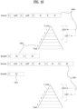
- FIG. 8 illustrates an example of point configuration in each LOD according to embodiments.
- the point cloud encoder may classify (or reorganize) points by LOD.
- the figure shows the point cloud content corresponding to LODs.
- the leftmost picture in the figure represents original point cloud content.
- the second picture from the left of the figure represents distribution of the points in the lowest LOD, and the rightmost picture in the figure represents distribution of the points in the highest LOD. That is, the points in the lowest LOD are sparsely distributed, and the points in the highest LOD are densely distributed. That is, as the LOD rises in the direction pointed by the arrow indicated at the bottom of the figure, the space (or distance) between points is narrowed.
- the point cloud content providing system may generates an LOD.
- the LOD is generated by reorganizing the points into a set of refinement levels according to a set LOD distance value (or a set of Euclidean distances).
- the LOD generation process is performed not only by the point cloud encoder, but also by the point cloud decoder.
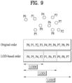
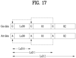
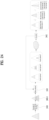
- FIG. 9 shows examples (P0 to P9) of points of the point cloud content distributed in a 3D space.
- the original order represents the order of points P0 to P9 before LOD generation.
- the LOD based order represents the order of points according to the LOD generation. Points are reorganized by LOD. Also, a high LOD contains the points belonging to lower LODs.
- LOD0 contains P0, P5, P4 and P2.
- LOD1 contains the points of LOD0, P1, P6 and P3.
- LOD2 contains the points of LOD0, the points of LOD1, P9, P8 and P7.
- the point cloud encoder may perform prediction transform coding, lifting transform coding, and RAHT transform coding selectively or in combination.
- the point cloud encoder may generate a predictor for points to perform prediction transform coding for setting a predicted attribute (or predicted attribute value) of each point. That is, N predictors may be generated for N points.
- the predicted attribute (or attribute value) is set to the average of values obtained by multiplying the attributes (or attribute values) (e.g., color, reflectance, etc.) of neighbor points set in the predictor of each point by a weight (or weight value) calculated based on the distance to each neighbor point.
- the point cloud encoder according to the embodiments e.g., the coefficient quantizer 40011
- the quantization process is configured as shown in the following table.
- the point cloud encoder (e.g., the arithmetic encoder 40012) according to the embodiments may perform entropy coding on the quantized and inversely quantized residual values as described above.
- the point cloud encoder according to the embodiments (e.g., the arithmetic encoder 40012) may perform entropy coding on the attributes of the corresponding point without performing the above-described operation.
- the point cloud encoder according to the embodiments (e.g., the lifting transformer 40010) may generate a predictor of each point, set the calculated LOD and register neighbor points in the predictor, and set weights according to the distances to neighbor points to perform lifting transform coding.
- the lifting transform coding according to the embodiments is similar to the above-described prediction transform coding, but differs therefrom in that weights are cumulatively applied to attribute values.
- the process of cumulatively applying weights to the attribute values according to embodiments is configured as follows.
- the point cloud encoder (for example, the RAHT transformer 40008) according to the embodiments may perform RAHT transform coding in which attributes of nodes of a higher level are predicted using the attributes associated with nodes of a lower level in the octree.
- RAHT transform coding is an example of attribute intra coding through an octree backward scan.
- the point cloud encoder according to the embodiments scans the entire region from the voxel and repeats the merging process of merging the voxels into a larger block at each step until the root node is reached.
- the merging process according to the embodiments is performed only on the occupied nodes.
- the merging process is not performed on the empty node.
- the merging process is performed on an upper node immediately above the empty node.
- g l x,y,z denotes the average attribute value of voxels at level 1.
- g l x,y,z may be calculated based on g l+1 2x,y,z and g l+1 2x+1,y,z .
- g l -1 x,y,z is a low-pass value and is used in the merging process at the next higher level.
- h l -1 x,y,z denotes high-pass coefficients.
- the high-pass coefficients at each step are quantized and subjected to entropy coding (e.g., encoding by the arithmetic encoder 400012).
- the root node is created through the g 1 0,0,0 and g 1 0,0,1 as follows.
- gDC h 0 0 , 0,0 T w1000 w1001 g 1 0 , 0,0 z g 1 0 , 0,1
- the value of gDC is also quantized and subjected to entropy coding like the high-pass coefficients.
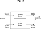
- FIG. 10 illustrates a point cloud decoder according to embodiments.
- the point cloud decoder illustrated in FIG. 10 is an example of the point cloud video decoder 10006 described in FIG. 1 , and may perform the same or similar operations as the operations of the point cloud video decoder 10006 illustrated in FIG. 1 .
- the point cloud decoder may receive a geometry bitstream and an attribute bitstream contained in one or more bitstreams.
- the point cloud decoder includes a geometry decoder and an attribute decoder.
- the geometry decoder performs geometry decoding on the geometry bitstream and outputs decoded geometry.
- the attribute decoder performs attribute decoding based on the decoded geometry and the attribute bitstream, and outputs decoded attributes.
- the decoded geometry and decoded attributes are used to reconstruct point cloud content (a decoded point cloud).
- FIG. 11 illustrates a point cloud decoder according to embodiments.
- the point cloud decoder illustrated in FIG. 11 is an example of the point cloud decoder illustrated in FIG. 10 , and may perform a decoding operation, which is a reverse process to the encoding operation of the point cloud encoder illustrated in FIGS. 1 to 9 .
- the point cloud decoder may perform geometry decoding and attribute decoding.
- the geometry decoding is performed before the attribute decoding.
- the arithmetic decoder 11000, the octree synthesizer 11001, the surface approximation synthesizer 11002, and the geometry reconstructor 11003, and the coordinate inverse transformer 11004 may perform geometry decoding.
- the geometry decoding according to the embodiments may include direct decoding and trisoup geometry decoding.
- the direct coding and trisoup geometry decoding are selectively applied.
- the geometry decoding is not limited to the above-described example, and is performed as a reverse process to the geometry encoding described with reference to FIGS. 1 to 9 .
- the arithmetic decoder 11000 decodes the received geometry bitstream based on the arithmetic coding.
- the operation of the arithmetic decoder 11000 corresponds to the reverse process to the arithmetic encoder 40004.
- the octree synthesizer 11001 may generate an octree by acquiring an occupancy code from the decoded geometry bitstream (or information on the geometry secured as a result of decoding).
- the occupancy code is configured as described in detail with reference to FIGS. 1 to 9 .
- the surface approximation synthesizer 11002 may synthesize a surface based on the decoded geometry and/or the generated octree.
- the geometry reconstructor 11003 may regenerate geometry based on the surface and/or the decoded geometry. As described with reference to FIGS. 1 to 9 , direct coding and trisoup geometry encoding are selectively applied. Accordingly, the geometry reconstructor 11003 directly imports and adds position information about the points to which direct coding is applied. When the trisoup geometry encoding is applied, the geometry reconstructor 11003 may reconstruct the geometry by performing the reconstruction operations of the geometry reconstructor 40005, for example, triangle reconstruction, up-sampling, and voxelization. Details are the same as those described with reference to FIG. 6 , and thus description thereof is omitted.
- the reconstructed geometry may include a point cloud picture or frame that does not contain attributes.
- the coordinate inverse transformer 11004 may acquire positions of the points by transforming the coordinates based on the reconstructed geometry.
- the arithmetic decoder 11005, the inverse quantizer 11006, the RAHT transformer 11007, the LOD generator 11008, the inverse lifter 11009, and/or the color inverse transformer 11010 may perform the attribute decoding described with reference to FIG. 10 .
- the attribute decoding according to the embodiments includes region adaptive hierarchical transform (RAHT) decoding, interpolation-based hierarchical nearest-neighbor prediction (prediction transform) decoding, and interpolation-based hierarchical nearest-neighbor prediction with an update/lifting step (lifting transform) decoding.
- RAHT region adaptive hierarchical transform
- prediction transform interpolation-based hierarchical nearest-neighbor prediction
- interpolation-based hierarchical nearest-neighbor prediction with an update/lifting step (lifting transform) decoding The three decoding schemes described above may be used selectively, or a combination of one or more decoding schemes may be used.
- the attribute decoding according to the embodiments is not limited to the above-described example.
- the inverse quantizer 11006 inversely quantizes the information about the decoded attribute bitstream or attributes secured as a result of the decoding, and outputs the inversely quantized attributes (or attribute values).
- the inverse quantization may be selectively applied based on the attribute encoding of the point cloud encoder.
- the RAHT transformer 11007, the LOD generator 11008, and/or the inverse lifter 11009 may process the reconstructed geometry and the inversely quantized attributes. As described above, the RAHT transformer 11007, the LOD generator 11008, and/or the inverse lifter 11009 may selectively perform a decoding operation corresponding to the encoding of the point cloud encoder.
- the color inverse transformer 11010 performs inverse transform coding to inversely transform a color value (or texture) included in the decoded attributes.
- the operation of the color inverse transformer 11010 may be selectively performed based on the operation of the color transformer 40006 of the point cloud encoder.
- the elements of the point cloud decoder of FIG. 11 may be implemented by hardware including one or more processors or integrated circuits configured to communicate with one or more memories included in the point cloud providing device, software, firmware, or a combination thereof.
- the one or more processors may perform at least one or more of the operations and/or functions of the elements of the point cloud decoder of FIG. 11 described above. Additionally, the one or more processors may operate or execute a set of software programs and/or instructions for performing the operations and/or functions of the elements of the point cloud decoder of FIG. 11 .
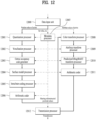
- FIG. 12 illustrates a transmission device according to embodiments.
- the transmission device shown in FIG. 12 is an example of the transmission device 10000 of FIG. 1 (or the point cloud encoder of FIG. 4 ).
- the transmission device illustrated in FIG. 12 may perform one or more of the operations and methods the same as or similar to those of the point cloud encoder described with reference to FIGS. 1 to 9 .
- the transmission device may include a data input unit 12000, a quantization processor 12001, a voxelization processor 12002, an octree occupancy code generator 12003, a surface model processor 12004, an intra/inter-coding processor 12005, an arithmetic coder 12006, a metadata processor 12007, a color transform processor 12008, an attribute transform processor 12009, a prediction/lifting/RAHT transform processor 12010, an arithmetic coder 12011 and/or a transmission processor 12012.
- the data input unit 12000 receives or acquires point cloud data.
- the data input unit 12000 may perform an operation and/or acquisition method the same as or similar to the operation and/or acquisition method of the point cloud video acquirer 10001 (or the acquisition process 20000 described with reference to FIG. 2 ).
- the data input unit 12000, the quantization processor 12001, the voxelization processor 12002, the octree occupancy code generator 12003, the surface model processor 12004, the intra/inter-coding processor 12005, and the arithmetic coder 12006 perform geometry encoding.
- the geometry encoding according to the embodiments is the same as or similar to the geometry encoding described with reference to FIGS. 1 to 9 , and thus a detailed description thereof is omitted.
- the quantization processor 12001 quantizes geometry (e.g., position values of points).
- the operation and/or quantization of the quantization processor 12001 is the same as or similar to the operation and/or quantization of the quantizer 40001 described with reference to FIG. 4 . Details are the same as those described with reference to FIGS. 1 to 9 .
- the voxelization processor 12002 voxelizes the quantized position values of the points.
- the voxelization processor 12002 may perform an operation and/or process the same or similar to the operation and/or the voxelization process of the quantizer 40001 described with reference to FIG. 4 . Details are the same as those described with reference to FIGS. 1 to 9 .
- the octree occupancy code generator 12003 performs octree coding on the voxelized positions of the points based on an octree structure.
- the octree occupancy code generator 12003 may generate an occupancy code.
- the octree occupancy code generator 12003 may perform an operation and/or method the same as or similar to the operation and/or method of the point cloud encoder (or the octree analyzer 40002) described with reference to FIGS. 4 and 6 . Details are the same as those described with reference to FIGS. 1 to 9 .
- the surface model processor 12004 may perform trisoup geometry encoding based on a surface model to reconstruct the positions of points in a specific region (or node) on a voxel basis.
- the surface model processor 12004 may perform an operation and/or method the same as or similar to the operation and/or method of the point cloud encoder (e.g., the surface approximation analyzer 40003) described with reference to FIG. 4 . Details are the same as those described with reference to FIGS. 1 to 9 .
- the intra/inter-coding processor 12005 may perform intra/inter-coding on point cloud data.
- the intra/inter-coding processor 12005 may perform coding the same as or similar to the intra/inter-coding described with reference to FIG. 7 . Details are the same as those described with reference to FIG. 7 .
- the intra/inter-coding processor 12005 may be included in the arithmetic coder 12006.
- the arithmetic coder 12006 performs entropy encoding on an octree of the point cloud data and/or an approximated octree.
- the encoding scheme includes arithmetic encoding.
- the arithmetic coder 12006 performs an operation and/or method the same as or similar to the operation and/or method of the arithmetic encoder 40004.
- the metadata processor 12007 processes metadata about the point cloud data, for example, a set value, and provides the same to a necessary processing process such as geometry encoding and/or attribute encoding. Also, the metadata processor 12007 according to the embodiments may generate and/or process signaling information related to the geometry encoding and/or the attribute encoding. The signaling information according to the embodiments may be encoded separately from the geometry encoding and/or the attribute encoding. The signaling information according to the embodiments may be interleaved.
- the color transform processor 12008, the attribute transform processor 12009, the prediction/lifting/RAHT transform processor 12010, and the arithmetic coder 12011 perform the attribute encoding.
- the attribute encoding according to the embodiments is the same as or similar to the attribute encoding described with reference to FIGS. 1 to 9 , and thus a detailed description thereof is omitted.
- the color transform processor 12008 performs color transform coding to transform color values included in attributes.
- the color transform processor 12008 may perform color transform coding based on the reconstructed geometry.
- the reconstructed geometry is the same as described with reference to FIGS. 1 to 9 . Also, it performs an operation and/or method the same as or similar to the operation and/or method of the color transformer 40006 described with reference to FIG. 4 is performed. A detailed description thereof is omitted.
- the attribute transform processor 12009 performs attribute transformation to transform the attributes based on the reconstructed geometry and/or the positions on which geometry encoding is not performed.
- the attribute transform processor 12009 performs an operation and/or method the same as or similar to the operation and/or method of the attribute transformer 40007 described with reference to FIG. 4 . A detailed description thereof is omitted.
- the prediction/lifting/RAHT transform processor 12010 may code the transformed attributes by any one or a combination of RAHT coding, prediction transform coding, and lifting transform coding.
- the prediction/lifting/RAHT transform processor 12010 performs at least one of the operations the same as or similar to the operations of the RAHT transformer 40008, the LOD generator 40009, and the lifting transformer 40010 described with reference to FIG. 4 .
- the prediction transform coding, the lifting transform coding, and the RAHT transform coding are the same as those described with reference to FIGS. 1 to 9 , and thus a detailed description thereof is omitted.
- the arithmetic coder 12011 may encode the coded attributes based on the arithmetic coding.
- the arithmetic coder 12011 performs an operation and/or method the same as or similar to the operation and/or method of the arithmetic encoder 400012.
- the transmission processor 12012 may transmit each bitstream containing encoded geometry and/or encoded attributes and metadata information, or transmit one bitstream configured with the encoded geometry and/or the encoded attributes and the metadata information.
- the bitstream may include one or more sub-bitstreams.
- the bitstream according to the embodiments may contain signaling information including a sequence parameter set (SPS) for signaling of a sequence level, a geometry parameter set (GPS) for signaling of geometry information coding, an attribute parameter set (APS) for signaling of attribute information coding, and a tile parameter set (TPS) for signaling of a tile level, and slice data.
- the slice data may include information about one or more slices.
- One slice according to embodiments may include one geometry bitstream Geom0 0 and one or more attribute bitstreams Attr0 0 and Attr1 0 .
- a slice refers to a series of syntax elements representing the entirety or part of a coded point cloud frame.
- the TPS may include information about each tile (e.g., coordinate information and height/size information about a bounding box) for one or more tiles.
- the geometry bitstream may contain a header and a payload.
- the header of the geometry bitstream according to the embodiments may contain a parameter set identifier (geom_parameter_set_id), a tile identifier (geom_tile_id) and a slice identifier (geom_slice_id) included in the GPS, and information about the data contained in the payload.
- the metadata processor 12007 may generate and/or process the signaling information and transmit the same to the transmission processor 12012.
- the elements to perform geometry encoding and the elements to perform attribute encoding may share data/information with each other as indicated by dotted lines.
- the transmission processor 12012 according to the embodiments may perform an operation and/or transmission method the same as or similar to the operation and/or transmission method of the transmitter 10003. Details are the same as those described with reference to FIGS. 1 and 2 , and thus a description thereof is omitted.
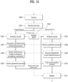
- FIG. 13 illustrates a reception device according to embodiments.
- the reception device illustrated in FIG. 13 is an example of the reception device 10004 of FIG. 1 (or the point cloud decoder of FIGS. 10 and 11 ).
- the reception device illustrated in FIG. 13 may perform one or more of the operations and methods the same as or similar to those of the point cloud decoder described with reference to FIGS. 1 to 11 .
- the reception device may include a receiver 13000, a reception processor 13001, an arithmetic decoder 13002, an occupancy code-based octree reconstruction processor 13003, a surface model processor (triangle reconstruction, up-sampling, voxelization) 13004, an inverse quantization processor 13005, a metadata parser 13006, an arithmetic decoder 13007, an inverse quantization processor 13008, a prediction/lifting/RAHT inverse transform processor 13009, a color inverse transform processor 13010, and/or a renderer 13011.
- Each element for decoding according to the embodiments may perform a reverse process to the operation of a corresponding element for encoding according to the embodiments.
- the receiver 13000 receives point cloud data.
- the receiver 13000 may perform an operation and/or reception method the same as or similar to the operation and/or reception method of the receiver 10005 of FIG. 1 . The detailed description thereof is omitted.
- the reception processor 13001 may acquire a geometry bitstream and/or an attribute bitstream from the received data.
- the reception processor 13001 may be included in the receiver 13000.
- the arithmetic decoder 13002, the occupancy code-based octree reconstruction processor 13003, the surface model processor 13004, and the inverse quantization processor 1305 may perform geometry decoding.
- the geometry decoding according to embodiments is the same as or similar to the geometry decoding described with reference to FIGS. 1 to 10 , and thus a detailed description thereof is omitted.
- the arithmetic decoder 13002 may decode the geometry bitstream based on arithmetic coding.
- the arithmetic decoder 13002 performs an operation and/or coding the same as or similar to the operation and/or coding of the arithmetic decoder 11000.
- the occupancy code-based octree reconstruction processor 13003 may reconstruct an octree by acquiring an occupancy code from the decoded geometry bitstream (or information about the geometry secured as a result of decoding).
- the occupancy code-based octree reconstruction processor 13003 performs an operation and/or method the same as or similar to the operation and/or octree generation method of the octree synthesizer 11001.
- the surface model processor 13004 may perform trisoup geometry decoding and related geometry reconstruction (e.g., triangle reconstruction, up-sampling, voxelization) based on the surface model method.
- the surface model processor 13004 performs an operation the same as or similar to that of the surface approximation synthesizer 11002 and/or the geometry reconstructor 11003.
- the inverse quantization processor 13005 may inversely quantize the decoded geometry.
- the metadata parser 13006 may parse metadata contained in the received point cloud data, for example, a set value.
- the metadata parser 13006 may pass the metadata to geometry decoding and/or attribute decoding.
- the metadata is the same as that described with reference to FIG. 12 , and thus a detailed description thereof is omitted.
- the arithmetic decoder 13007, the inverse quantization processor 13008, the prediction/lifting/RAHT inverse transform processor 13009 and the color inverse transform processor 13010 perform attribute decoding.
- the attribute decoding is the same as or similar to the attribute decoding described with reference to FIGS. 1 to 10 , and thus a detailed description thereof is omitted.
- the arithmetic decoder 13007 may decode the attribute bitstream by arithmetic coding.
- the arithmetic decoder 13007 may decode the attribute bitstream based on the reconstructed geometry.
- the arithmetic decoder 13007 performs an operation and/or coding the same as or similar to the operation and/or coding of the arithmetic decoder 11005.
- the inverse quantization processor 13008 may inversely quantize the decoded attribute bitstream.
- the inverse quantization processor 13008 performs an operation and/or method the same as or similar to the operation and/or inverse quantization method of the inverse quantizer 11006.
- the prediction/lifting/RAHT inverse transform processor 13009 may process the reconstructed geometry and the inversely quantized attributes.
- the prediction/lifting/RAHT inverse transform processor 13009 performs one or more of operations and/or decoding the same as or similar to the operations and/or decoding of the RAHT transformer 11007, the LOD generator 11008, and/or the inverse lifter 11009.
- the color inverse transform processor 13010 according to the embodiments performs inverse transform coding to inversely transform color values (or textures) included in the decoded attributes.
- the color inverse transform processor 13010 performs an operation and/or inverse transform coding the same as or similar to the operation and/or inverse transform coding of the color inverse transformer 11010.
- the renderer 13011 may render the point cloud data.
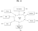
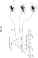
- FIG. 14 illustrates an exemplary structure operable in connection with point cloud data transmission/reception methods/devices according to embodiments.
- FIG. 14 represents a configuration in which at least one of a server 1460, a robot 1410, a self-driving vehicle 1420, an XR device 1430, a smartphone 1440, a home appliance 1450, and/or a head-mount display (HMD) 1470 is connected to the cloud network 1400.
- the robot 1410, the self-driving vehicle 1420, the XR device 1430, the smartphone 1440, or the home appliance 1450 is called a device.
- the XR device 1430 may correspond to a point cloud data (PCC) device according to embodiments or may be operatively connected to the PCC device.
- PCC point cloud data
- the cloud network 1400 may represent a network that constitutes part of the cloud computing infrastructure or is present in the cloud computing infrastructure.
- the cloud network 1400 may be configured using a 3G network, 4G or Long Term Evolution (LTE) network, or a 5G network.
- LTE Long Term Evolution
- the server 1460 may be connected to at least one of the robot 1410, the self-driving vehicle 1420, the XR device 1430, the smartphone 1440, the home appliance 1450, and/or the HMD 1470 over the cloud network 1400 and may assist in at least a part of the processing of the connected devices 1410 to 1470.
- the HMD 1470 represents one of the implementation types of the XR device and/or the PCC device according to the embodiments.
- the HMD type device according to the embodiments includes a communication unit, a control unit, a memory, an I/O unit, a sensor unit, and a power supply unit.
- the devices 1410 to 1450 illustrated in FIG. 14 may be operatively connected/coupled to a point cloud data transmission device and reception device according to the above-described embodiments.
- the XR/PCC device 1430 may employ PCC technology and/or XR (AR+VR) technology, and may be implemented as an HMD, a head-up display (HUD) provided in a vehicle, a television, a mobile phone, a smartphone, a computer, a wearable device, a home appliance, a digital signage, a vehicle, a stationary robot, or a mobile robot.
- HMD head-up display
- AR+VR XR
- the XR/PCC device 1430 may analyze 3D point cloud data or image data acquired through various sensors or from an external device and generate position data and attribute data about 3D points. Thereby, the XR/PCC device 1430 may acquire information about the surrounding space or a real object, and render and output an XR object. For example, the XR/PCC device 1430 may match an XR object including auxiliary information about a recognized object with the recognized object and output the matched XR object.
- the XR/PCC device 1430 may be implemented as a mobile phone 1440 by applying PCC technology.
- the mobile phone 1440 may decode and display point cloud content based on the PCC technology.
- the self-driving vehicle 1420 may be implemented as a mobile robot, a vehicle, an unmanned aerial vehicle, or the like by applying the PCC technology and the XR technology.
- the self-driving vehicle 1420 to which the XR/PCC technology is applied may represent a self-driving vehicle provided with means for providing an XR image, or a self-driving vehicle that is a target of control/interaction in the XR image.
- the self-driving vehicle 1420 which is a target of control/interaction in the XR image may be distinguished from the XR device 1430 and may be operatively connected thereto.
- the self-driving vehicle 1420 having means for providing an XR/PCC image may acquire sensor information from sensors including a camera, and output the generated XR/PCC image based on the acquired sensor information.
- the self-driving vehicle 1420 may have an HUD and output an XR/PCC image thereto, thereby providing an occupant with an XR/PCC object corresponding to a real object or an object present on the screen.
- the XR/PCC object When the XR/PCC object is output to the HUD, at least a part of the XR/PCC object may be output to overlap the real object to which the occupant's eyes are directed. On the other hand, when the XR/PCC object is output on a display provided inside the self-driving vehicle, at least a part of the XR/PCC object may be output to overlap an object on the screen.
- the self-driving vehicle 1220 may output XR/PCC objects corresponding to objects such as a road, another vehicle, a traffic light, a traffic sign, a two-wheeled vehicle, a pedestrian, and a building.
- VR virtual reality
- AR augmented reality
- MR mixed reality
- PCC point cloud compression
- the VR technology is a display technology that provides only CG images of real-world objects, backgrounds, and the like.
- the AR technology refers to a technology that shows a virtually created CG image on the image of a real object.
- the MR technology is similar to the AR technology described above in that virtual objects to be shown are mixed and combined with the real world.
- the MR technology differs from the AR technology in that the AR technology makes a clear distinction between a real object and a virtual object created as a CG image and uses virtual objects as complementary objects for real objects, whereas the MR technology treats virtual objects as objects having equivalent characteristics as real objects.
- an example of MR technology applications is a hologram service.
- the VR, AR, and MR technologies are sometimes referred to as extended reality (XR) technology rather than being clearly distinguished from each other. Accordingly, embodiments of the present disclosure are applicable to any of the VR, AR, MR, and XR technologies.
- the encoding/decoding based on PCC, V-PCC, and G-PCC techniques is applicable to such technologies.
- the PCC method/device according to the embodiments may be applied to a vehicle that provides a self-driving service.
- a vehicle that provides the self-driving service is connected to a PCC device for wired/wireless communication.
- the device may receive/process content data related to an AR/VR/PCC service, which may be provided together with the self-driving service, and transmit the same to the vehicle.
- the PCC transmission/reception device may receive/process content data related to the AR/VR/PCC service according to a user input signal input through a user interface device and provide the same to the user.
- the vehicle or the user interface device according to the embodiments may receive a user input signal.
- the user input signal according to the embodiments may include a signal indicating the self-driving service.
- point cloud data is composed of a set of points, each of which may have geometry data (geometry information) and attribute data (attribute information).
- the geometry data is the three-dimensional position of each point (e.g., the coordinate values of the x, y, and z axes). That is, the position of each point is indicated by parameters in a coordinate system representing a three-dimensional space (e.g., the parameters (x, y, z) of the three axes representing the space, the x, y, and z axes).
- the attribute information may represent color (RGB, YUV, etc.), reflectance, normal vectors, and transparency.
- the attribute information may be represented in the form of a scalar or vector.
- point cloud data may be classified into category 1 for static point cloud data, category 2 for dynamic point cloud data, and category 3 for point cloud data acquired through dynamic movement, depending on the type and acquisition method of the point cloud data.
- Category 1 is composed of a point cloud of a single frame with a high density of points for an object or space.
- Category 3 data may be divided into frame-based data with multiple frames acquired while moving, and fused data of a single frame matching a point cloud acquired for a large space by a LiDAR sensor with a color image acquired as a 2D image.
- the point cloud data transmission method/device is construed as a term referring to the transmission device 10000, point cloud video encoder 10002, and transmitter 10003 in FIG. 1 , the acquisition 20000/encoding 20001/transmission 20002 in FIG. 2 , the encoder in FIG. 4 , the transmission device in FIG. 12 , the device in FIG. 14 , the encoders in FIGS. 15 and 24 , the encoders in FIGS. 36 to 38 , the transmission methods in FIGS. 25 , 27 , and 39 , and the like.
- the point cloud data reception method/device is construed as a term referring to the reception device 10004, receiver 10005, and point cloud video decoder 10006 in FIG. 1 , the transmission 20002/decoding 20003/rendering 20004 in FIG. 2 , the decoder in FIGS. 10 and 11 , the reception device in FIG. 13 , the device in FIG. 14 , the decoders in FIGS. 15 and 24 , the decoders in FIGS. 36 to 38 , the reception method in FIGS. 26 , 30 , and 40 , and the like.
- the method/device for transmitting/receiving point cloud data according to the embodiments may be referred to as a method/device according to the embodiments.
- Geometry data may be referred to as geometry information, position information, or the like.
- Attribute data according to embodiments may be referred to as attribute information, or the like.
- the method/device may carry out a method of segmenting and transmitting/receiving point cloud data for local access (slice segmentation for spatial random access).
- Embodiments include a method for efficiently supporting selective decoding of a part of data due to a receiver performance or a transmission speed in transmitting and receiving point cloud data, when necessary.
- Embodiments include a method for selecting necessary information or removing unnecessary information in a bitstream unit by dividing geometry and attributes delivered per data unit into semantic units such as geometry octree and Level of Detail (LoD).
- Embodiments include a method of configuring a data structure composed of a point cloud. More specifically, embodiments disclose a packing and signaling method for effectively transferring PCC data configured based on a layer, and include a method of applying the packing and signaling method to a scalable PCC based service. In particular, embodiments include a method of configuring slice segments and transmitting and receiving the same so as to be more suitable for a scalable PCC service when a direct compression mode is used for position compression. Also, embodiments may provide a compression structure for efficiently storing and transmitting mass point cloud data having a wide distribution and high point density.
- point cloud data is composed of a position (e.g., XYZ coordinates) and attributes (e.g., color, reflectance, intensity, grayscale, opacity, etc.) of each datum.
- attributes e.g., color, reflectance, intensity, grayscale, opacity, etc.
- FIGS. 4 and 11 are flowcharts for the transmitting and receiving sides of the PCC. Operations according to embodiments may be processed by each component of the transmitting and receiving sides of the PCC.
- FIG. 15 illustrates a process of encoding, transmission, and decoding point cloud data according to embodiments.
- the components of the processes or methods illustrated in FIG. 15 may be processes or methods performed by hardware, software, processors, and/or any combination thereof.
- a point cloud encoder 15000 is a point cloud data transmission device according to embodiments carrying out a transmission method according to embodiments, and may scalably encode and transmit point cloud data.
- a point cloud decoder 15010 is a reception device according to embodiments carrying out a reception method according to embodiments, and may scalably decode the point cloud data.
- the source data received by the encoder 15000 may be point cloud data, including geometry data and/or attribute data.
- the encoder 15000 may scalably encode the point cloud data and not directly generate a partial PCC bitstream. Instead, when it receives full geometry data and full attribute data, it may store the data in a storage connected to the encoder. Then, the encoder may perform transcoding for partial encoding, and generate and transmit a partial PCC bitstream.
- the decoder 15010 may receive and decode the partial PCC bitstream to reconstruct partial geometry and/or partial attributes.
- the encoder 15000 may store the data in the storage connected to the encoder, and transcode the point cloud data with a low quantization parameter (QP) to generate and transmit a complete PCC bitstream.
- QP quantization parameter
- the decoder 15010 may receive and decode the complete PCC bitstream to reconstruct full geometry and/or full attributes. Also, the decoder 15010 may select a partial geometry and/or a partial attribute from the complete PCC bitstream through data selection.
- the method/device compresses and transmits the point cloud data by dividing the position information about data points and feature information such as color/brightness/reflectance, which are the point cloud data, into geometry information and attribute information.
- an octree structure having layers may be configured according to the degree of detail or PCC data may be configured according to levels of detail (LoDs).
- scalable point cloud data coding and representation may be performed based the configured structure or data. In this case, only a part of the point cloud data may be decoded or represented due to the performance of the receiver or the transfer rate.
- the method/device according to the embodiments may remove unnecessary data in advance.
- the necessary part needs to be re-encoded (15020) after decoding, or 2) the receiver should selectively apply the bitstream after the whole bitstream is transferred thereto
- the method/device according to the embodiments may define a slice segmentation structure of point cloud data, and signal a scalable layer and slice structure for scalable transmission.
- the bitstream may be divided into specific units to be processed.
- the method/device for transmitting and receiving point cloud data may use entropy-based coding and direct coding together. In this case, a slice configuration for efficiently utilizing scalability is needed.
- the point cloud data transmission/reception method/device may address a delay issue caused by a large amount of bitstream that is processed to access a region of interest in processing a large amount of point cloud data having a wide distribution and high point density.
- the point cloud data transmission/reception method/device may employ a hierarchical point cloud data structure for low-delay compression of a large amount of point cloud data.
- the hierarchical point cloud data structure may represent a tree structure, such as an octree or levels of detail (LoD).
- the encoder process may utilize a save and load encoder, a geometry occupancy atlas update, and the like.
- the decoder process may utilize detection of parent subgroups, input parent node selection, and the like.
- the transmission/reception method/ device may perform level of detail (LoD) generation, weight derivation, and LoD to layer-group mapping.
- LoD level of detail
- the tree structure may represent a data structure that progressively increases in data density with level or depth.
- the tree structure may be constructed in a variety of ways in addition to the octree or LoD.
- signaling information related to a scalable layer and slice structure for scalable transmission is proposed.
- a definition of a layer group and/or a subgroup and slice segmentation are proposed.
- a hierarchical point cloud data structure for low-delay compression of a large amount of point cloud data is proposed.
- FIG. 16 shows a layer-based point cloud data configuration and a structure of geometry and attribute bitstreams according to embodiments.
- the transmission/reception method/device may configure layer-based point cloud data, as shown in FIG. 16 , for efficient transmission and decoding by selective delivery and decoding of data in a bitstream unit.
- the transmission/reception method/device may configure layer-based point cloud data as shown in FIG. 16 to encode and decode the point cloud data.
- Layering of point cloud data may have a layer structure in terms of SNR, spatial resolution, color, temporal frequency, bit depth, or the like depending on the application field, and may configure layers in a direction in which data density increases based on the octree structure or LOD structure.
- the methods/devices according to the embodiments may configure, encode, and decode a geometry bitstream and an attribute bitstream based on the layering as shown in FIG. 16 .
- a bitstream acquired through point cloud compression by the transmission device/encoder according to the embodiments may be divided into a geometry data bitstream and an attribute data bitstream according to the type of data and transmitted.
- Each bitstream according to the embodiments may be composed of slices. Regardless of layer information or LoD information, the geometry data bitstream and the attribute data bitstream may each be configured as one slice and delivered. In this case, when only a part of the layers or LoDs is to be used, operations of 1) decoding the bitstream, 2) selecting only a desired part and removing unnecessary parts, and 3) performing encoding again based on only the necessary information may be required.
- FIG. 17 shows a bitstream configuration according to embodiments.
- the transmission method/device according to the embodiments may generate a bitstream as shown in FIG. 17
- the reception method/device according to the embodiments may decode point cloud data contained in the bitstream as shown in FIG. 17 .
- Embodiments may employ a method of dividing the bitstream into layers (levels of LoD or depths of an octree) to avoid unnecessary intermediate steps.
- a lower LoD is included in a higher LoD.
- Information included in the current LoD but not included in the previous LoD, that is, information newly included in each LoD may be referred to as R (Rest).
- R (Rest) information newly included in each LoD.
- the initial LoD information and the information R newly included in each LoD may be divided and transmitted in each independent unit.
- the transmission method/device may encode geometry data and generate a geometry bitstream.
- a geometry bitstream may be configured for each LOD or layer.
- the geometry bitstream may include a header (geometry header) for each LOD or layer.
- the header may include reference information for the next LOD or the next layer.
- the current LOD (or layer) may further include information R (geometry data), which is not included in the previous LOD (or layer).
- the transmission method/device may encode attribute data and generate an attribute bitstream.
- An attribute bitstream may be configured for each LOD or layer, and the attribute bitstream may include a header (attribute header) for each LOD or layer.
- the header may include reference information for the next LOD or the next layer.
- the current LOD (layer) may further include information R (attribute data), which is not included in the previous LOD (layer).
- the reception method/device may receive a bitstream composed of LODs or layers and efficiently decode only necessary data without any complicated intermediate process.
- FIG. 18 illustrates a bitstream sorting method according to embodiments.
- the method/device according to the embodiments may sort the bitstreams of FIG. 17 as shown in FIG. 18 .
- the transmission method/device may serially transmit geometry and attributes as shown in FIG. 18 .
- the whole geometry information may be transmitted first, and then the attribute information (attribute data) may be transmitted.
- the geometry information may be quickly reconstructed based on the delivered bitstream information.
- layers (LODs) containing geometry data may be positioned first in the bitstream, and layers (LODs) containing attribute data may be positioned after the geometry layers. Since the attribute data is dependent on the geometry data, the geometry layer may be placed first. In addition, the positions may be changed differently according to embodiments. Reference may also be made between geometry headers or between an attribute header and a geometry header.
- bitstreams constituting the same layer containing geometry data and attribute data may be collected and delivered.
- the decoding execution time may be shortened.
- information that needs to be processed first (lower LoD, wherein geometry must precede attribute) may be placed first.
- a first layer 1800 contains geometry data and attribute data corresponding to the lowest LOD 0 (layer 0) along with each header.
- a second layer 1810 includes LOD 0 (layer 0), and also contains geometry data and attribute data about points for a new and more detailed layer 1 (LOD 1), which are not included in LOD 0 (layer 0), as information R1.
- a third layer 1820 may be subsequently placed in a similar manner.
- the transmission/reception method/device may efficiently select a layer (or LoD) desired in an application field at a bitstream level when a bitstream is transmitted and received.
- collecting and transmitting geometry information may produce an empty part in the middle after the bitstream level selection. In this case, the bitstream may need to be rearranged.
- unnecessary information may be selectively removed according to the application field as follows.
- FIG. 19 illustrates a method of selecting geometry data and attribute data according to embodiments.
- the method/device may select data at the bitstream level as shown in FIG. 19 : 1) symmetric selection of geometry and attributes; 2) asymmetrical selection of geometry and attributes; or 3) A combination of the two methods.
- FIG. 19 shows a case where data belonging to LoD1 (LOD 0 +R1) is selected (19000) and transmitted or decoded, and information corresponding to R2 (the new part of LOD 2) corresponding to a higher layer is removed (19010) to transmit and decode the data.
- the method/device according to the embodiments may deliver geometry and attributes asymmetrically. Attribute R2 19011 of a higher layer may be removed, and all the geometry (from level 0 (root level) to level 7 (leaf level) of an octree structure of a triangle) may be selected and transmitted/decoded (19001).
- the scalability function may include slice level scalability and/or octree level scalability.
- the level of detail (LoD) may be used as a unit for representing a set of one or more octree layers.
- it may mean a bundle of octree layers to be configured as a slice.
- the LOD according to the embodiments may be extended and used as a unit for dividing data in detail in a broader sense.
- Spatial scalability by an actual octree layer may be provided for each octree layer.
- selection may be made in LoDs according to embodiments.
- LOD0 may correspond to the root level to level 4
- LOD1 may correspond to the root level to level 5
- LOD2 may correspond to the root level to level 7, which is the leaf level.
- the provided scalable step may correspond to three steps of LoD0, LoD1, and LoD2, and the scalable step that may be provided by the octree structure in the decoding operation may correspond to eight steps from the root to the leaf.
- a transcoder (the transcoder 15040 of FIG. 15 ) of the receiver or the transmitter may 1) select LoD0 only, 2) select LoD0 and LoD1, or 3) select LoD0, LoD1, and LoD2, for scalable processing.
- Example 1 When only LoD0 is selected, the maximum octree level may be 4, and one scalable layer may be selected from among octree layers 0 to 4 in the decoding process. In this case, the receiver may consider a node size obtainable through the maximum octree depth as a leaf node, and may transmit the node size through signaling information.
- Example 2 When LoD0 and LoD1 are selected, layer 5 may be added.
- the maximum octree level may be 5, and one scalable layer may be selected from among octree layers 0 to 5 in the decoding process.
- the receiver may consider a node size obtainable through the maximum octree depth as a leaf node, and may transmit the node size through signaling information.
- an octree depth, an octree layer, and an octree level may represent units into which data is divided in detail.
- Example 3 When LoD0, LoD1, and LoD2 are selected, layers 6 and 7 may be added.
- the maximum octree level may be 7, and one scalable layer may be selected from among octree layers 0 to 7 in the decoding process.
- the receiver may consider a node size obtainable through the maximum octree depth as a leaf node, and may transmit the node size through signaling information.
- FIG. 20 illustrates a method of configuring a slice including point cloud data according to embodiments.
- FIG. 20 illustrates slice configuration according to embodiments
- the transmission method/device/encoder may configure a G-PCC bitstream by segmenting the bitstream in a slice structure.
- a data unit for detailed data representation may be a slice.
- a slice according to embodiments may mean a data unit in which point cloud data is partitioned. That is, a slice represents a portion of the point cloud data.
- one or more octree layers may be matched to one slice.
- the transmission method/device may configure a bitstream based on a slice 2001 by scanning a node (point) included in an octree in the direction of scan order 2000.
- some nodes in an octree layer may be included in one slice.
- the octree layers may constitute one slice 2002.
- Partial data of an octree layer may constitute each slice 2003, 2004, 2005.
- Partial data of an octree layer may constitute each slice.
- FIGS. 20-(b) and 20-(c) when multiple octree layers are matched to one slice, only some nodes (or points) of each layer may be included. In this way, when multiple slices constitute one geometry/attribute frame, information necessary to configure a layer may be delivered for the receiver.
- the information may include information about layers included in each slice and information about nodes included in each layer.
- octree layers for example, level 0 to level 3 and partial data of level 4 may be configured as one slice.
- Partial data of octree layers may be configured as one slice.
- Partial data of octree layers for example, partial data of level 5 and partial data of level 6 may be configured as one slice.
- Partial data of an octree layer may be configured as one slice.
- data of octree layers may be configured as one slice.
- Partial data from each of octree layer level 5, level 6, and level 7 may be configured as one slice.
- a slice may contain data that corresponds to multiple octree layers.
- a slice may contain some data from octree layer level 5 and data from octree layer level 6 or octree layer level 7 corresponding to the child nodes of that data.
- the encoder and the device corresponding to the encoder may encode the point cloud data, and generate and transmit a bitstream containing the encoded data and parameter information related to the point cloud data.
- the bitstream may be generated based on the bitstream structure according to embodiments (see, for example, FIGS. 16 to 20 ). Accordingly, the reception device, the decoder, and a corresponding device according to the embodiments may receive and parse a bitstream configured to be suitable for selective partial data decoding, and partially decode and efficiently provide the point cloud data (see FIG. 15 ).
- the point cloud data transmission method/device according to the embodiments may scalably transmit a bitstream containing point cloud data, and the point cloud data reception method/device according to the embodiments may scalably receive and decode the bitstream.
- Scalable transmission may mean transmitting or decoding only a part of a bitstream, rather than decoding the entire bitstream, and the result thereof may be low resolution point cloud data.
- point cloud data When scalable transmission is applied to the octree-based geometry bitstream, point cloud data should be allowed to be configured with information ranging up to a specific octree layer for the bitstream of each of the octree layers ( FIG. 16 ) from a root node to a leaf node.
- the target octree layer should have no dependency on information about the lower octree layer. This may be a restriction applied to geometry coding and attribute coding in common.
- a scalable structure used for the transmitter/receiver to select a scalable layer needs to be delivered.
- all octree layers may support the scalable transmission.
- the scalable transmission may be allowed only for a specific octree layer or lower layers.
- a scalable layer in which the slice is included may be indicated, such that it may be determined whether the slice is necessary/unnecessary in the bitstream stage. In the example of FIG.
- the yellow part starting from the root node constitutes one scalable layer without supporting scalable transmission
- following octree layers may be matched to scalable layers in a one-to-one correspondence manner.
- scalability may be supported for a part corresponding to the leaf node.
- FIG. 23-(c) when multiple octree layers are included in a slice, it may be defined that one scalable layer shall be configured for the layers.
- scalable transmission and scalable decoding may be used separately for different purposes.
- the scalable transmission may be used at the transmitting/receiving side for the purpose of selecting information up to a specific layer without involving a decoder.
- the scalable decoding is used to select a specific layer during coding. That is, the scalable transmission may support selection of necessary information without involving a decoder in a compressed state (in the bitstream stage), such that the information may be determined by the transmitter or receiver.
- the scalable decoding may support encoding/decoding data only up to a necessary part in the encoding/decoding, and may thus be used in such a case as scalable representation.
- the layer configuration for scalable transmission may be different from the layer configuration for scalable decoding.
- the three bottom octree layers including the leaf node may constitute one layer in terms of scalable transmission.
- scalable decoding when all layer information is included, scalable decoding may be performed for each of leaf node layer, leaf node layer-1, leaf node layer-2.
- FIG. 21 illustrates a geometry coding layer structure according to embodiments.
- a G-PCC bitstream may be sliced into multiple sub-bitstreams.
- each slice may include coded data from a partial coding layer or a partial region.
- a slice segment may contain data coded from a layer group defined as follows.
- a layer group may be defined as a group of contiguous tree layers, wherein the start and end depths of the group of tree layers may be arbitrary numbers in the tree depth, and the start depth may be less than the end depth.
- the order of the data coded in a slice segment may be the same as the order of the data coded in a single slice.
- the decoded output will be partial layers 0 to 5, as shown in (b) of FIG. 21 .
- partial decoding of coding layers may be supported without accessing the entire bitstream.
- the bitstream and point cloud data according to the embodiments may be generated based on coding layer-based slice segmentation.
- the method/device according to the embodiments may select a related slice, thereby supporting scalable transmission or partial decoding.
- FIG. 21-(a) shows a geometry coding layer structure with 8 layers in which each slice corresponds to a layer group.
- Layer group 1 2100 includes coding layers 0 to 4.
- Layer group 2 2101 includes coding layer 5.
- Layer group 3 2102 is a group for coding layers 6 and 7.
- a geometry or attribute
- a bitstream may be hierarchically configured by grouping data corresponding to one or more levels (depths). Each group may be included in one slice.
- FIG. 21-(b) shows the decoded output when selecting two slices from among three groups.
- the decoder selects group 1 and group 2
- partial layers of levels (depths) 0 to 5 of the tree are selected. That is, partial decoding of coding layers may be supported by using the slices of the layer group structure, even without accessing the entire bitstream.
- the encoder according to the embodiments may generate three slices generated based on the layer group structure.
- the decoder according to the embodiments may perform partial decoding by selecting two slices from among the three slices.
- a bitstream according to embodiments may include layer group-based slices 2104 and 2105.
- Each slice may include a header containing signaling information related to point cloud data (geometry data and/or attribute data) included in the slice.
- the reception method/device according to the embodiments may select slices and decode point cloud data contained in the payload of the slices based on the header included in the slices.
- the method/device according to the embodiments may further divide the layer group into several subgroups (subgroups) in consideration of use cases of spatial random access in addition to the layer group structure.
- the subgroups are mutually exclusive, and a set of subgroups may be the same as a layer group. Since the points of each subgroup form a boundary in the spatial domain, the subgroup may be represented by subgroup bounding box information.
- the layer group and subgroup structure may support access to a region of interest (ROI) by selecting slices that cover the ROI.. By efficiently comparing the ROI with the bounding box information about each slice, spatial random access within a frame or tile may be supported.
- ROI region of interest
- a method/device according to embodiments may configure slices for delivering point cloud data, as shown in FIG. 21 .
- the entire coded bitstream may be included in a single slice.
- each slice may contain a sub-bitstream.
- the order of the slices may be the same as the order of the sub-bitstreams.
- Each slice may be matched to a layer group in a tree structure.
- Slices may not affect previous slices, just as higher layers of the geometry tree do not affect lower layers.
- the segmented slices according to the embodiments are effective in terms of error robustness, effective transmission, support of region of interest, and the like.
- segmented slices may be more resilient to errors.
- data loss may affect the entire frame data.
- slices that are not affected by the loss may be decoded even when some other slices are lost.
- decoders having different capabilities may be supported.
- the LOD of the coded point cloud may be determined prior to encoding. Accordingly, multiple pre-encoded bitstreams having different resolutions of the point cloud data may be independently transmitted, which may be inefficient in terms of large bandwidth or storage space.
- the single bitstream may support decoders of different levels. From the decoder perspective, the receiver may select target layers and may deliver the partially selected bitstream to the decoder. Similarly, by using a single PCC bitstream without partitioning the entire bitstream, a partial PCC bitstream may be efficiently generated at the transmitting side.
- a compressed bitstream may be configured to have one or more layers.
- a particular ROI may have additional layers and a higher density, and the layers may be predicted from lower layers.
- the decoder may increase the resolution of the ROI at the request.
- This operation may be implemented using the geometry octree and the scalable structure of G-PCC such as the scalable attribute coding scheme.
- inefficiency may be caused in terms of bandwidth, memory, and decoder.
- the decoder according to the embodiments may efficiently select slices as needed.
- a method/device may generate a layer group using a tree structure (or layer structure) of the point cloud data.
- a group represents a group of layers. For example, group 1 includes layers 0 to 4, group 2 includes layer 5, and group 3 includes layers 6 and 7.
- group 1 includes layers 0 to 4
- group 2 includes layer 5
- group 3 includes layers 6 and 7.
- the tree structure is identical to the geometry tree structure.
- the same octree-slice mapping may be used to create attribute slice segments.
- a layer group according to the embodiments represents a bundle of layer structure units generated in G-PCC coding, such as an octree layer or a LoD layer.
- a sub-group may be represented as a set of neighboring nodes within a layer group. It may be configured as a set of neighboring nodes by Morton code order, a set of neighboring nodes based on distance, or a set of neighboring nodes based on coding order. Nodes in a parent-child relationship may also be present within a subgroup.
- a boundary occurs in the middle of the layer, and whether there is entropy continuation at the boundary may be signaled by a parameter such as entropy_continuation_enabled_flag. Continuation may also be maintained by referencing the previous slice through ref slice_id.
- the tree structure according to the embodiments may be an octree structure, and the attribute layer structure or attribute coding tree according to the embodiments may include a level of detail (LOD) structure.
- LOD level of detail
- the tree structure for the point cloud data may include layers corresponding to depths or levels, and the layers may be grouped.
- a method/device may generate an octree structure of geometry or an LOD tree structure of attributes. Further, the point cloud data may be grouped based on layers of the tree structure.
- multiple layers are grouped into a first to third group.
- a group may be further divided into subgroups within it to form subgroups.
- a slice may contain coded data from a layer group.
- the layer group is defined as a group of consecutive tree layers, wherein the start and end depths of the tree layers may be specific numbers in the tree depth, wherein the start is less than the end.
- FIG. 21 illustrates the geometry coding layer structure as an example of a tree structure
- a coding layer structure for attributes may be created similarly.
- FIG. 22 illustrates a structure of a layer group and subgroups according to embodiments.
- point cloud data and bitstreams may be bounded and represented by bounding boxes.
- Layer groups 2 and 3 are divided into two subgroups (group2-1, group2-2) and four subgroups (group3-1, group3-2, group3-3, group3-4), respectively, and are contained in different slices.
- spatial access may be performed by 1) comparing the bounding box of each slice with the ROI, 2) selecting a slice where the subgroup bounding box overlaps with the ROI, and 3) decoding the selected slice.
- slices 1, 3, and 6 are selected as subgroup bounding boxes of layer group 1 and subgroups 2-2 and 3-3 that cover the ROI. It is assumed that there is no dependency between subgroups from the same layer group for effective spatial access. For live streaming or low-latency use cases, selection and decoding may be performed as each slice segment is received to increase time efficiency.
- a method/device may represent data as a tree 2200 consisting of layers (which may be referred to as depths, levels, etc.) in encoding geometry and/or attributes.
- Point cloud data corresponding to layers (depths/ levels) may be grouped into layer groups (or groups) 2201. Each layer group may be further divided (segmented) into subgroups 2202. Each subgroup may be configured as a slice to generate a bitstream.
- the reception device may receive the bitstream, select a specific slice, decode a subgroup included in the slice, and decode a bounding box corresponding to the subgroup. For example, when slice 1 is selected, a bounding box 2203 corresponding to layer group 1 may be decoded. Layer group 1 may be data corresponding to the largest region. When displaying an additional detailed region for layer group 1, a method/device according to the embodiments may select slice 3 and/or slice 6, and may hierarchically and partially access the bounding box (point cloud data) of subgroup 2-2 and/or subgroup 3-3 for detailed regions included in the region of layer group 1.
- the encoding and decoding of point cloud data by the layer groups and subgroups of FIG. 22 may be performed by the transmission/reception devices of FIG. 1 , the encoding and decoding of FIG. 2 , the transmission device/method of FIG. 4 , the reception device/method of FIG. 11 , the transmission/reception devices/methods of FIGS. 12 and 13 , the devices of FIG. 14 , the encoder and decoder of FIG. 15 , the encoder and decoder of FIG. 24 , the encoders and decoders of FIGS. 36 to 38 , and the transmission/reception methods of FIGS. 39 and 40 .
- FIG. 23 illustrates a representation of layer group-based point cloud data according to embodiments.
- Devices/methods according to embodiments may provide efficient access to large-scale point cloud data or dense point cloud data with layer group slicing based on scalability and spatial access capabilities.
- Point cloud data may take a significant amount of time to render or display content due to the high number of points and the large size of the data. Therefore, as an alternative approach, the level of detail may be adjusted based on the viewer's interest. For example, when a viewer is far away from a scene or object, structural or global region information is more important than local detailed information, whereas when the viewer moves closer to a specific region or object, detailed information about the ROI is needed.
- the renderer according to embodiments may efficiently provide data of sufficient quality to the viewer.
- FIG. 23 illustrates an example of increasing detail for three levels of viewing distance that changes based on ROI.
- the high-level view in FIG. 23 shows coarse detail
- the mid-level view shows medium-level detail
- the low-level view shows fine-grained detail
- FIG. 24 illustrates devices/methods for transmitting and receiving point cloud data according to embodiments.
- Multi-resolution ROI may be supported when layer group slicing is used to generate a G-PCC bitstream.
- multi-resolution ROIs may be supported by the scalability and spatial accessibility of hierarchical slicing.
- the encoder 2400 may generate bitstream slices of spatial subgroups of each layer group or bitstream slices of octree layer groups. Upon request, slices matching the ROI of each resolution are selected and transmitted. The size of the entire bitstream is reduced compared to the tile-based approach, as it does not include details beyond the requested ROI.
- the decoder 2402 may combine the slices to produce three outputs: 1) a high-level view output from layer group slice 1; 2) a mid-level view output from layer group slice 1 and selected subgroups of layer group 2; and 3) a low-level view output of good quality details from selected subgroups of layer groups 2 and 3 and layer group 1. Since the outputs may be generated progressively, the receiver may provide a viewing experience such as zooming in which the resolution progressively increases from the high-level view to the low-level view.
- the encoder 2400 may correspond to a geometry encoder and an attribute encoder as a point cloud encoder according to embodiments.
- the encoder may slice the point cloud data based on layer groups (or groups).
- a layer may be referred to as a depth of a tree, a level of LOD, or the like.
- the depth of the octree of the geometry and/or the level of the attribute layer may be divided into layer groups (or sub-groups).
- the slice selector 2401 in conjunction with the encoder 2400, may select a split slice (or sub-slices) and selectively and partially transmit data such as layer group 1 to layer group 3.
- the decoder 2402 may decode the selectively and partially transmitted point cloud data. For example, it may decode a high-level view based on layer group 1 (which has a high depth/layer/level or an index of 0, or is close to root). Thereafter, the mid-level view may be decoded by increasing the index of the depth/level over layer group 1 alone based on layer group 1 and layer group 2. The low-level view may be decoded based on layer group 1 to layer group 3.
- the encoder 2400 may receive point cloud data as input and slice the same into layer groups. That is, the point cloud data may be hierarchically structured and divided into layer groups.
- the hierarchical structure may refer to an octree structure or level of detail (LoD).
- Part 2400-1 represents the point cloud data divided into layer groups.
- the slice selector 2401 may select layer groups (or corresponding slices), and the selected slices are sent to the decoder 2402.
- the decoder 2402 may reconstruct only layer group 1, reconstruct layer groups 1 and 2, or reconstruct all received layer groups by combining the received slices as desired by the user.
- the layer groups are hierarchical and have different levels of detail. Reconstructing only layer group 1 may result in a broader range of reconstruction and less detail. Reconstructing all layer groups 1 to 3 may result in a narrower range of reconstruction and more detail.
- FIG. 25 illustrates an encoding method according to embodiments.
- the encoding of the point cloud data of FIG. 25 may be performed by the transmission device of FIG. 1 , the encoding of FIG. 2 , the transmission device/method of FIG. 4 , the transmission device/method of FIG. 12 , the devices of FIG. 14 , the encoder of FIG. 15 , the encoder of FIG. 24 , the encoders of FIGS. 36 to 38 , and/or the transmission method of FIG. 39 , or any combination thereof.
- the encoding method may include performing encoding with reference to context information based on layer groups and subgroups.
- the context information may be referred to as context state information, encoder state information, or the like.
- the transmission/reception device/method according to the embodiments may divide the point cloud data into layer groups (or subgroups), and may encode and decode the point cloud data based on the layer groups.
- a geometry bitstream may be divided into slices on a per layer-group/subgroup basis, and geometry position information may be efficiently compressed and reconstructed.
- the layer-group slicing according to the embodiments may restrict the use of information about nodes outside the subgroup bounding box. In this case, the continuation of a context reference may be used to reduce the loss of coding efficiency.
- Context information used in coding one slice may be used when coding another slice.
- the context information may be used based on a correlation between nodes present in one geometry tree to enhance coding efficiency.
- a context reference relationship may be established when a subgroup bounding box of a reference slice includes or is the same as a subgroup bounding box of a referenced slice.
- the coding efficiency may be increased by using the context information.
- context information about a first slice may be used for encoding/decoding of a following slice.
- a node outside a subgroup bounding box is a non-occupied node. That is, when the geometry position information about each node is coded, nodes present in a slice in which each node is included, that is, nodes belonging to the same subgroup may be taken as neighbors. Based on this, neighbor occupancy information about a coding target node may be determined. In this case, for a fast implementation, occupancy information about a neighbor node may be stored in an atlas. In using occupancy information about a node in the atlas, it may be additionally determined whether the node is within the range of the bbox_max and bbox_min of a bounding box of a subgroup to which the current node belongs to selectively use only nodes belonging to the subgroup. This ensures that each subgroup within a layer-group may be coded independently by not allowing neighbor node information belonging to other subgroups to be used in coding a node.
- a layer-group index and a subgroup index of each node are determined, and a reference context according to each index may be used as an initial value of the context information at the start of each subgroup.
- a node may be present regardless of a subgroup order, and the context information may be ensured to be continuously used in a subgroup through a process of storing and loading an encoder context state.
- the transmission and reception devices determine whether a layer-group is changed, and perform different operations according to the determination.
- the parent-child node relationship between nodes in a tree structure may be represented as a connection between a node at a lower level and a node at a higher level.
- a box area containing a certain number of nodes may represent a layer group or subgroup.
- the layer group or subgroup may correspond to one or more slices.
- the point cloud data transmission/reception device/method may perform encoding/decoding by loading context information based on a reference layer group, a reference subgroup, or a reference slice. That is, the grouped point cloud data may be encoded/decoded based on the context information.
- the transmission/reception device/method may perform arithmetic encoding on the point cloud data belonging to a layer group or subgroup and save the context information, and may load the saved context information to perform arithmetic encoding on the point cloud data belonging to a layer group or subgroup.
- the point cloud data transmission/reception device/method may perform encoding/decoding by loading saved contexts of a reference layer group, a reference subgroup, or a reference slice.
- the reference layer group, reference subgroup, or reference slice may include nodes corresponding to a parent of nodes belonging to the layer group, subgroup, or slice to be encoded/decoded.
- the point cloud data transmission/reception device/method encodes/decodes a second group based on context information about the first group, and saves the context information about the second group.
- the saved context information about the second group may be used to encode/decode a third group.
- the first group to the third group may be groups based on arbitrary layers.
- the first group may be a group corresponding to a lower layer than the second group. More specifically, the first group may be a group corresponding to a parent of the second group.
- the nodes belonging to a lower level layer may be nodes that correspond to parents of nodes belonging to a higher level layer.
- the point cloud data transmission/reception device/method may save the context of a parent layer group, a parent subgroup, or a parent slice, and may use the saved contexts in encoding/decoding of a child layer group, a child subgroup, or a child slice.
- the parent group or slice may be positioned at a lower level than the child group or slice in the tree structure, and a node belonging to the parent group (layer group or subgroup)/slice may have a parent-child relationship with a node belonging to the child group/slice.
- the point cloud data transmission device/method may set or initialize a context, a neighbor search range, or planar buffer information whenever a depth or a level of a tree structure (e.g., octree or LOD) starts, or at a start point of a layer group (or a subgroup or a slice) or an octree depth in which layer groups (or subgroups, slices) are consecutive.
- the time when the depth (or layer) of the tree structure starts indicates when the leftmost node is reached in the depth (or layer) of the tree structure.
- the initialization or setting of the aforementioned information may not be performed.
- the current layer group, subgroup, or slice may be encoded/decoded by continuing the context of a reference layer group, a reference subgroup, or a reference slice based on the association between layer groups, subgroups, or slices in encoding and decoding the point cloud data.
- the point cloud data transmission/reception device/method according to the embodiments improves the compression efficiency of the bitstream by using information related to the reference layer group, reference subgroup, or reference slice.
- Applying context continuation may mean continuously using context information (context model, arithmetic model, or probability range information) about a related reference layer group, a related reference subgroup, or a related reference slice in the encoding/decoding operation.
- the point cloud data transmission/reception device/method according to the embodiments may continuously use a context based on a reference group (a reference layer group or a reference subgroup) or a reference slice related to a current group (layer group or subgroup) or slice. Whether continuation of the context is available (whether there is a relation between slices or groups) may be defined through signaling information.
- the transmission/reception device/method may encode/decode the current slice or the current group based on the context information related to the reference slice or the reference group. That is, the current slice or group may be encoded/decoded by applying context continuation.
- the context information according to the embodiments may refer to point cloud data, for example, additional information generated in encoding and/or decoding geometry data and/or attribute data by the arithmetic encoder and/or arithmetic decoder of FIGS. 4 and 11 .
- the current point cloud data in encoding/decoding current point cloud data in the encoding and/or decoding according to the embodiments, the current point cloud data may be efficiently compressed and reconstructed based on context information calculated based on previous point cloud data.
- Arithmetic encoding is one of the entropy encoding algorithms used for lossless compression. Arithmetic encoding may replace the entire message with a single real number n.
- Arithmetic coding may divide a range of 0.0 to 1.0 based on the probability of appearance of symbols appearing in the message. For example, suppose that the probability of appearance of symbol "a" in the message is 60%, the probability of appearance of symbol "b” in the message is 20%, and the probability of appearance of symbol "c" in the message is 20%.
- the range of 0.0 to 1.0 is may be divided into a range of 0.0 to 0.6 representing the probability of appearance of symbol "a,” a range of 0.6 to 0.8 representing the probability of appearance of symbol "b,” and a range of 0.8 to 1.0 representing the probability of appearance of symbol "c.”
- the ratio at which the probability range such as 0.0 to 1.0 is divided is called a probability model (or probability mode) or a context model.
- the first coded symbol is "a,” and thus it corresponds to the range of 0.0 to 0.6.
- the range of 0.0 to 0.6 corresponding to "a” is again divided into proportions of 60% 20%, and 20%. Accordingly, the range of 0.0 to 0.6 may be divided into a range of 0.0 to 0.36, a range of 0.36 to 0.48, and a range of 0.48 to 0.6.
- the second encoded symbol is "b,” and thus it corresponds to the range of 0.36 to 0.48.
- the range of 0.36 to 0.48 corresponding to "b" When the range of 0.36 to 0.48 corresponding to "b" is further divided into proportions of 60%, 20%, and 20%, it may be divided into a range of 0.36 to 0.432, a range of 0.432 to 0.456, and a range of 0.456 to 0.48.
- the third encoded symbol is "c,” and thus it corresponds to the range of 0.456 to 0.48. That is, in the arithmetic encoding, a range corresponding to an encoded symbol is divided again according to a probability model or a context model, and then any one of the ranges divided according to the next encoded symbol is selected. By repeating this process, arithmetic encoding is operated.
- the probability range derived after encoding the message "abc" corresponds to the range of 0.456 to 0.48. Accordingly, the message “abc” may be encoded into a real number within the range. For example, the real number 0.47 may represent ".”
- the value of 0.47 is transmitted to the decoder according to the embodiments. The decoder may check the probability range to which the value of 0.47 belongs in the probability range divided according to the context model, and decode the message into a symbol corresponding to the probability range.
- the probability model (or probability mode) or context model may be a model that is initially determined according to an arithmetic encoding algorithm, or a model configured by checking the probability of appearance of symbols in performing the encoding/decoding.
- the probability model or the context model may be updated during the encoding/decoding operation.
- the point cloud data transmission/reception device applies context continuation in performing encoding/decoding, which means continuously encoding the current slice or the current group in continuation with a probability range calculated by arithmetic coding of the reference slice or the reference group.
- context continuation means continuously encoding the current slice or the current group in continuation with a probability range calculated by arithmetic coding of the reference slice or the reference group.
- the last probability range derived in arithmetic encoding of the reference slice is 0.456 to 0.48
- the range from 0.456 to 0.48 may be divided again according to the context model or the probability model to continuously encode the current slice. That is, a probability range or a context model may not be initialized for every slice or group (layer group or subgroup). Instead, the current slice may be encoded/decoded in continuation with the probability range of the reference slice derived through relation search.
- the point cloud data transmission/reception device/method may use context-adaptive binary arithmetic coding (CABAC).
- CABAC context-adaptive binary arithmetic coding
- a context model (or probability mode) used for arithmetic encoding of a slice or a group may be initialized for every slice or group, or a probability mode used in a related reference slice or reference group may be reused in the current slice or the current group.
- the current slice may be encoded continuously in the probability range derived from the related reference slice, or may be decoded using the probability range information.
- inter-symbol redundancy may be utilized by reusing the probability mode. Thereby, the compression efficiency may be increased.
- Using the same probability mode as the probability mode used in the reference slice has the same meaning as using the context model of the reference slice. Even in arithmetic coding, Huffman coding, or range coding other than CABAC, the probability mode or context model of the reference slice may be reused.
- the inputs to the layer group slicing encoder are point cloud data and parameters describing the structure of the layer group slicing.
- the layer group of the target tree depth may be determined using the layer group structure parameters.
- the subgroup index of each node may be determined using the subgroup bounding box.
- the range of the geometry occupancy atlas may be updated considering subgroup boundaries above the atlas boundary. Both methods ensure that each coded bitstream can be decoded independently, without node information about the neighbor subgroups. This process may be performed recursively for all nodes in all tree depths. When the end of the node at the target tree depth is reached, fine granularity slices (FGS) are generated that are matched one-to-one with subgroups of each layer group. The technique used for independent decoding is described in code below.
- the layer group of the tree layer is determined and fixed for all tree depths within the layer group. Since a layer group is a set of consecutive tree layers, the layer group index changes at the start of the layer group. With a fixed layer group, subgroups are determined. Since a subgroup is a set of nodes bounded within a subgroup bounding box, the subgroup of a node is found by comparing the position of the node and the subgroup bounding box. Whenever a subgroup or layer group is changed, the encoder state (or context information) of the previous subgroup is saved for future use, and the encoder state (or context information) of the current subgroup is loaded for continuous encoding.
- the transmission/reception device/method according to the embodiments may encode or decode the point cloud data by referencing context states (or context information) between subgroups or between layer groups.
- the transmission/reception device/method according to the embodiments may determine whether the node corresponds to a subgroup by comparing information indicative of the position of the node with the bounding box information related to the subgroup. Then, context information may be referenced based on whether the node belongs to the subgroup.
- the transmission/reception device/method according to embodiments may update the geometry occupancy atlas.
- _maxRange and _minRange may be defined in the MortonMap3D class. If the atlas is in a subgroup, the _maxRange and _minRange may be set to 0 and the edge length of the cube, respectively. If the minimum boundary of the subgroup is greater than the minimum value of the atlas, _minRange may be set to the minimum value of the subgroup boundary. If the maximum boundary of the subgroup is less than the maximum value of the atlas, _maxRange may be set to the maximum value of the subgroup boundary.
- a transmission device/method may perform operations including determining a layer group (S2501), determining a subgroup belonging to the layer group (S2502), determining whether the subgroup has changed (S2503).
- the subgroup may save and load context state information (S2504).
- it updates the geometry occupancy atlas (S2505).
- the geometry occupancy atlas may be updated immediately (S2505).
- the determining the layer group (S2501), determining the subgroup (S2502), determining whether the subgroup has changed (S2503), and updating the atlas (S2505) may be performed according to the code described above.
- the transmission/reception device/method may determine the subgroup to which a node belongs by comparing information indicative of the position of the node with the bounding box information (minimum and maximum values) of the subgroup. Accordingly, the node may be encoded or decoded by loading context information based on the subgroup and layer group to which the node belongs, and the node may be encoded or decoded by referencing the saved context information related to another subgroup or layer group.
- the node may be encoded (S2506), and it may be determined whether the node is the last in the subgroup (S2507). Based on the result of the determination, the process may be repeated for all nodes (or points) corresponding to the layer group or subgroup. Once all nodes at a given depth in the tree structure are encoded, it may be determined whether the depth is the last in the tree structure (S2508) and the process may be repeated for the next depth based on the result of the determination.
- a data unit header may be generated to generate signaling information about the reference relationship of the context information, and the reception device/method according to the embodiments may decode the point cloud data based on the signaling information.
- FIG. 26 illustrates a decoding method according to embodiments.
- the decoding of the layer group and subgroup based point cloud data in FIG. 26 may be performed by the reception device of FIG. 1 , the decoding of FIG. 2 , the reception device/method of FIG. 11 , the reception device/method of FIG. 13 , the devices of FIG. 14 , the decoder of FIG. 15 , the decoder of FIG. 24 , the decoder of FIGS. 36 to 38 , the transmission and reception methods of FIG. 40 , or any combination thereof.
- the decoding process of the layer group slicing reference SW for the first fine granularity slice includes parsing a parameter set, parsing a data unit header and decoding a data unit.
- following dependent geometry data units may be considered as the FGSs for the first slice if they have the same slice ID.
- the order of FGSs is assumed to be sorted in ascending order by layer_group_id and subgroup_id.
- the context state, output nodes, and layer group parameters of the previous slice are saved in a buffer for the next slice.
- the parent of the current subgroup may be detected by finding a subgroup whose subgroup boundary box is a superset of the current subgroup boundary box. Once the parent subgroup is determined, the parent nodes of the current dependent data unit are selected. By using the selected nodes as the initial nodes for the decoding process, the current dependent data unit is decoded up to the tree layer covered by the current layer group. The decoding process of the dependent data units is performed recursively until the end of the geometry bitstream.
- the dependent data unit may correspond to a node, subgroup, or layer group.
- the nodes of the parent subgroup may be used as input to the child subgroups in order to provide continuous decoding within the layer group boundaries. This is due to the hierarchical structure of layer group slicing, and may be triggered based on a parent-child spatial relationship.
- a child subgroup is a subset of a parent subgroup, and the bounding box of the child subgroup is spatially exclusive from the bounding boxes of other child subgroups in the same layer group.
- a slice of a parent subgroup may be detected by finding a spatial superset of the current slice.
- the parent subgroup may be found by comparing the bounding box information about the subgroup at the previous layer group level with subgroup_bbox origin and subgroup_bbox_size signaled in the data unit header.
- the reception device/method may compare the boundary box information about the current subgroup with the boundary box information about other subgroups. Thereby, it may detect which of the other subgroups is the parent subgroup of the current subgroup. Then, to decode the current subgroup, the context information about the parent subgroup may be referenced. Thereby, efficient decoding may be performed.
- the starting point for searching for the parent subgroup index may be specified as the previous parent subgroup. This is based on the assumption that slices are ordered in the direction of increasing layer-group and subgroup, and slice reordering may be added if necessary.
- the output nodes of the parent subgroup may be used as input to decode the child subgroup.
- the subgroup bounding boxes of the parent subgroup and the child subgroup are the same, all nodes generated by the parent subgroup are used.
- the subgroup bounding box of the child subgroup is a subset of the parent subgroup, the decoder according to the embodiments needs to select actual parent nodes. To find the parent nodes, each node of the parent subgroup may be compared with the boundary bounding box of the child subgroup.
- the selection status of each node may be used. This is based on the condition that a parent node can be included in only one subgroup.
- all nodes in the parent subgroup may be parent nodes of the current subgroup.
- the parent node selection process may be omitted to increase decoder efficiency.
- the reception device/method includes parsing a data unit header and parsing a data unit.
- the data unit may include point cloud data according to embodiments, and the data unit header may include parameter information needed to decode the point cloud data.
- the parameter information may be the information disclosed in FIGS. 28 to 30 .
- the data unit may correspond to a slice that is matchable to a layer group or subgroup.
- the reception device/method according to the embodiments may determine whether layer-group slicing is enabled (S2601), and may operate differently in response to the result of the determination.
- layer-group slicing When layer-group slicing is performed, layer-group parameters and buffers may be updated (S2602) and the dependent data unit header may be parsed (S2603).
- the reception device/method according to the embodiments may then detect a parent subgroup (S2604) and select a parent node input (S2605) to decode the point cloud data. Then, it may parse the dependent data unit (S2606), determine whether the end of the bitstream is reached (S2607), and generate a point cloud output (S2608).
- the detecting the parent subgroup (S2604) and selecting the parent node input (S2605) described with reference to FIG. 26 may be performed by the code described above.
- FIG. 27 illustrates an encoding method according to embodiments.
- the encoding of the point cloud data of FIG. 27 may be performed by the transmission device of FIG. 1 , the encoding of FIG. 2 , the transmission device/method of FIG. 4 , the transmission device/method of FIG. 12 , the devices of FIG. 14 , the encoder of FIG. 15 , the encoder of FIG. 24 , the encoders of FIGS. 36 to 38 , and/or the transmission method of FIG. 39 , or any combination thereof.
- FIG. 27 is an example flowchart of a layer-group slicing encoder for LoD-based attribute coding.
- parameters such as a sequence parameter set (SPS), a geometry parameter set (GPS), an attribute parameter set (APS), and an LGSI are generated and a layer-group structure is configured.
- the configuration of the layer-group structure may be performed during or before the generation of the LGSI.
- LoD generation is performed based on the geometry nodes (S2701).
- an attribute coding layer e.g., LoD, RAHT coding layer
- a quantization weight is derived based on the LoD (S2703).
- the attribute coding layer is checked for layer-group changes, and the nodes within the attribute coding layer are checked for subgroup changes.
- the attribute encoder for the previous subgroup is saved and the attribute encoder for the current subgroup may be used to ensure continuity of contexts, zeroruns, etc. within the subgroup and to ensure independence from neighbor subgroups.
- the coded bitstreams for each subgroup are packed into respective slices.
- FIG. 27 illustrates LoD-based attribute coding
- the encoding according to the embodiments may be applied to other methods of attribute coding, such as RAHT.
- a transmission device/method may perform opertions including generating an LoD (S2701), mapping the LoD to a layer group (S2702), and deriving a weight (S2703).
- the operations may further include determining the layer group (S2704), determining a subgroup (S2705), checking whether the subgroup has changed (S2706), saving and loading context information (S2707), and encoding attribute information (S2708).
- the above process may be performed per node or per level of the LoD.
- the generating of the LoD may include subsampling, and building a predictor or performing a neighbor search.
- the building predictor or neighbor search may be performed based on the boundaries of the subgroups. For example, the neighbors of a first node may be selected from among the nodes positioned within the boundary of the subgroup to which the first node belongs.
- FIG. 28 illustrates a LoD generation procedure in which subgroups are considered according to embodiments.
- FIG. 28 may illustrate the generating of the LoD (S2701) in FIG. 27 .
- the generating of the LoD according to the embodiments may include subsampling, building a predictor, and performing a neighbor search.
- FIG. 28 illustrates the results of partial decoding depending on whether the boundaries of the subgroups are taken into account.
- FIG. 28 shows the processes of building a predictor and performing a neighbor search when the subgroup boundary is considered and when the subgroup boundary is not considered.
- neighbor node n3 may be selected that lies outside the subgroup boundary of the current node as the encoder selects neighbors based on distance in the neighbor search. In this case, when the decoder performs partial decoding, the neighbor node n3 may not be present, which may cause an unintended value to be output. Since the encoder may not transmit all subgroups to the decoder in partial decoding, information about the node selected by the encoder as the neighbor node n3 may not be delivered to the decoder.
- the transmission/reception device/method according to the embodiments may not select as neighbors nodes that are positioned outside the boundary of the subgroup 2804 to which the current node 2812 belongs, taking into account the boundary of the subgroup.
- a parent subgroup 2802 and child subgroups 2804 and 2806 are shown.
- nodes that are positioned outside the boundary of the subgroup 2804 are not selected as neighbors in building the predictor or performing the neighbor search.
- n1 and n2 may be selected as neighbors of the current node 2812.
- the boundary of the subgroup 2804 to which the current node belongs is not considered, even the node n3 positioned outside the boundary of the subgroup may be selected as a neighbor of the current node.
- the decoder may lack information needed to reconstruct the current node. For example, information about the node n3 described above may not be transmitted to the decoder.
- the decoder may reconstruct the current node even if information about some of the subgroups is transmitted to the decoder, because the decoder is capable of finding neighbor nodes within the subgroup to which the current node belongs.
- the transmission/reception device/method according to the embodiments may search for neighbors of the current node considering the subgroup boundary.
- a boundary for neighbor node search may be referred to as an intra-layer-group search boundary.
- the neighbor candidates may be in the same layer-group as the current node.
- the neighbor nodes may be searched for within the same subgroup boundary as the current node.
- the transmission/reception device/method may search for neighbors of the current node considering the subgroup boundary.
- a boundary for neighbor node search may be referred to as an inter-layer-group search boundary.
- the inter-layer-group search boundary may allow neighbors of the current node to be searched for in the parent subgroup of the current node or in a subgroup of the current node.
- the inter-layer-group search boundary may be used when the level of the LoD to which the current node belongs is the least dense in the layer group.
- the transmission/reception device/method according to the embodiments may be restricted to use only the nodes within the same subgroup bounding box in building a predictor. Thereby, segmented slices may be decoded through partial decoding. In this case, the root layer-group may be allowed to be referenced in all cases.
- a transmission/reception device/method may provide a corresponding attribute for a geometry bitstream that is partially decoded by applying layer-group slicing to the attribute bitstream.
- an attribute coding layer may be configured as follows. By matching the LoD based on the layer-group structure configured based on the geometry coding layer, the geometry output and the attribute output may be matched in the case of partial decoding.
- the method of generating a layer-group may affect compression efficiency because performance may vary due to changes in nearest neighbors depending on the LoD configuration.
- the transmission/reception device/method may match layer-groups to levels of the LoD generated during attribute encoding/decoding in a one-to-one correspondence manner, or may match a plurality of levels to a single layer-group. Then, based on the matched layer groups, the encoding/decoding may be performed with reference to context information about a relevant layer group, thereby increasing compression efficiency.
- the transmission/reception device/method according to the embodiments may match the layer groups or subgroups grouped based on a tree structure (such as an octree or LoD) configured in geometry encoding/decoding with the depths or levels of a tree structure (such as an octree or LoD) generated in attribute encoding/decoding. That is, the transmission/reception device/method according to the embodiments may generate a tree structure (e.g., a LoD) in attribute encoding/decoding and group the levels or depths of the tree structure into layer groups or subgroups. The grouping may be performed based on the layer groups or subgroups configured during the geometry encoding/decoding.
- a tree structure such as an octree or LoD
- the transmission/reception device/method according to the embodiments may generate a tree structure (e.g., a LoD) in attribute encoding/decoding and group the levels or depths of the tree structure into layer groups or subgroups.
- subgroup boundaries and layer-group boundaries may be considered for quantization weights.
- FIG. 29 illustrates a weight derivation procedure in which subgroups are applied according to embodiments.
- the weight derivation procedure illustrated in FIG. 29 may represent the weight derivation (S2703) of FIG. 27 .
- FIG. 29 illustrates a method of supporting partial decoding by restricting the quantization weight update to be performed only within a subgroup boundary in a leaf layer-group.
- FIG. 29 illustrates the difference in partial decoding results depending on whether a subgroup boundary is considered in weight derivation.
- the neighbor search is performed without considering child level subgroup boundaries, as in the previous neighbor search procedure. Therefore, neighbors are selected beyond the boundary based on the child level subgroup boundary.
- the weight for the first node 2922 is determined based on the weight or number of nodes that have selected the first node 2922 as a neighbor.
- decoding errors may occur if any node referencing the first node 2922 is lost. Therefore, one method to prevent this issue may be to align the parent-child subgroup boundaries and restrict only nodes within the child subgroup boundary to be selected as neighbors.
- the root layer-group is not subject to subdivision, and a fixed weight may be applied to the root layer-group as a method to support partial decoding.
- nodes positioned outside the boundary of the subgroup to which a node belongs may be selected as neighbors of the node or built as predictors during the predictor building and neighbor search by the encoder.
- the first node 2922 belonging to the parent subgroup is referenced by nodes belonging to a first child subgroup and a second child subgroup.
- the weight for the first node 2922 may be derived based on the number of nodes referencing the first node 2922.
- some subgroups may not be transmitted to the decoder. In this case, during weight derivation at the decoder, the weight for the first node may be derived differently from that derived by the encoder, which may result in decoding errors.
- the boundaries of the parent subgroup 2902 and the child subgroup 2908 may be aligned, and nodes positioned within the boundary of the subgroup to which a node 2914 belongs may be selected as neighbors of the node 2914 or built as predictors in the predictor building and neighbor search by the encoder. Further, in the weight derivation, the first node 2912 belonging to the parent subgroup is referenced by other nodes belonging to the same boundary, and thus the weight for the first node 2912 may be derived based on the number of referenced nodes.
- the weights for nodes belonging to the parent subgroup may be derived, even if some child subgroups are not transmitted to the decoder.
- the transmission/reception device/method may search for neighbor nodes within the boundary of the subgroup of the current point (or node) or build a predictor. Further, in the weight derivation, the weights for nodes belonging to the parent subgroup may be derived based on the boundary of the child subgroup. For example, in FIG. 29 , when the first node 2912 belonging to the parent subgroup 2902 is within the boundary of the first child subgroup 2908, the weight for the first node 2912 may be derived based on the number of nodes referencing the first node 2912 among the nodes belonging to the first child subgroup 2908. Thus, in partial decoding, even if the second child subgroup is not transmitted to the decoder, the decoder may derive the same weight for the first node, and reconstruct the data. Fixed weights may be derived for nodes belonging to the root layer group.
- quantization weights may be adaptively applied on a per-subgroup basis
- each attribute coding layer When each attribute coding layer is changed, it may be checked whether the layer-group is changed, and the subgroup is checked for each node in the coding layer to update the encoder information according to the subgroup.
- the zerorun may provide higher efficiency compression when zeros appear in a row. By providing continuity for zeroruns within the same layer-group and subgroup, additional compression efficiency may be provided even when the attribute coding layer changes.
- the save and update encoder described above may represent the save and load encoder (S2707) in FIG. 27 .
- the transmission/reception device/method may reference context information about a relevant layer group or subgroup based on the layer group or subgroup to which the current node (or point) belongs.
- the context information for the current node may be saved and may be loaded to reference the context information when encoding/decoding another node.
- the transmission/reception device/method may reference the context information about the parent group of the group to which the current node (or point) belongs in encoding/decoding the attribute. For example, it may reference the context information about the parent subgroup of the subgroup to which the current node belongs.
- the subgroup to which the current node belongs may be searched based on the bounding box information about the subgroup, and the parent subgroup of the subgroup to which the current node belongs may be searched by comparing the bounding box information.
- the information about the parent subgroup may be delivered by signaling, and may be derived by the reception device (e.g., decoder) based on the bounding box information.
- FIG. 30 illustrates a decoding method according to embodiments.
- the decoding of point cloud data based on the layer groups and subgroups of FIG. 30 may be performed by the reception device of FIG. 1 , the decoding of FIG. 2 , the reception device/method of FIG. 11 , the reception device/method of FIG. 13 , the devices of FIG. 14 , the decoder of FIG. 15 , the decoder of FIG. 24 , the decoder of FIGS. 36 to 38 , the reception method of FIG. 40 , or a combination thereof.
- the inputs to the attribute decoder are an attribute fine granularity slice bitstream, decode geometry data, and a layer-group structure.
- LoD generation is performed based on the decoded geometry data, and weight derivation is performed based on the relationship of nodes according to the LoD. Then, the generated information may be used in the subsequent attribute decoding.
- the first attribute slice may be operated in the same way as the previous attribute slice. Then, when layer-group slicing is enabled, the dependent attribute data unit header may be parsed and the layer_group_id and subgroup_id information may be acquired. Information about the LoD may be signaled, when necessary.
- a layer-group matching the current LoD may be found and a parent subgroup may be selected.
- the reference and parent information used in the geometry decoding may be used. Based on this, the information in the dependent attribute data unit may be decoded and the point cloud data may be reconstructed.
- the LoD generation and weight derivation methods used in the encoder may be used.
- the procedure of mapping a LoD to a layer-group is further described below.
- decoding methods may include generating a LoD (S3001) and deriving weights (S3002).
- S3001 and S3002 may correspond to the LoD generation and weight derivation described with reference to FIGS. 27 to 29 .
- the LoD generation and weight derivation in the decoding method according to the embodiments may be performed considering the boundaries of the subgroups.
- the generating the LoDs may include building a predictor and searching for neighbors. The building of the predictor and the neighbor search may be performed based on nodes that are within the boundary of the subgroup, considering the boundary of the subgroup to which the current node belongs.
- the decoding method includes parsing an attribute data unit header (S3003), decoding an attribute data unit (S3004), determining whether layer-group slicing is enabled (S3005), and based on the layer-group slicing beign enabled, parsing a dependent attribute data unit header (S3006). It may also include mapping a LoD to a layer-group (S3007), selecting a parent subgroup (S3008), and decoding a dependent attribute data unit.
- S3005 may be determined by the layer_group enabled flag.
- layer_group enabled flag When layer_group enabled flag is equal to 1, it indicates that layer_group slicing is enabled. Enabling the layer-group slicing may indicate that the point cloud data (geometry or attributes) is grouped into layer groups or subgroups for processing.
- the attributes contained in the dependent data unit may be decoded by mapping the LoD and layer-group (S3007), selecting the parent subgroup (S3008), based on the information described in FIG. 35 .
- the dependent attribute data unit header includes layer_group_id and subgroup_id, specifying the layer group index and subgroup index, and includes subgroup-specific bounding box origin information (subgroup_bbox origin[i]) and size information (subgroup_bbox_size[i]). It may also include ref layer_group_id, ref_subgroup_id to carry information about the reference layer group and reference subgroup. In addition, quant_weight may carry information about the quantization weight for the current subgroup.
- the layer_group_id and subgroup_id may be utilized in mapping the LoD to the layer group (S3007), and the subgroup bounding box origin information (subgroup_bbox origin[i]) and size information (subgroup_bbox size[i]) may be used to compare the bounding box information in selecting the parent subgroup (S3008).
- the decoding method may perform decoding by referencing context information based on the layer group and subgroup.
- the context information may be referred to as context state information, state information, or the like.
- the reference to the context information may be made by using signaling information such as ref_layer_group_id, ref subgroup_id, etc. or by deriving the parent subgroup based on the bounding box information about the subgroup.
- FIG. 31 illustrates a bitstream configuration according to embodiments.
- the method/device according to the embodiments may generate a bitstream as shown in FIG. 31 .
- the bitstream may contain encoded geometry data and attribute data, and also contain parameter information.
- the parameter information may include a slice structure for the layer configuration described with reference to FIGS. 15 to 30 and signaling information for scalable transmission.
- information on a separated slice may be defined in a parameter set of the bitstream and an SEI message as follows.
- the bitstream may contain a sequence parameter set (SPS), a geometry parameter set (GPS), an attribute parameter set (APS), a geometry slice header, and an attribute slice header.
- SPS sequence parameter set
- GPS geometry parameter set
- APS attribute parameter set
- a geometry slice header may be referred to as a geometry data unit header
- the attribute slice header may be referred to as an attribute data unit header. That is, the slice may be referred to as a data unit.
- the parameter information may have a different meaning depending on the position where the signal is transmitted.
- the signal When the signal is defined in the SPS, this may indicate that the signal is equally applied to the entire sequence.
- the signal is defined in the GPS this may indicate that the signal is used for position reconstruction.
- the signal When the signal is defined in the APS, this may indicate that the signal is applied to attribute reconstruction.
- the signal When the signal is defined in the TPS, this may indicate that the signal is applied only to the points in a tile.
- the signal is delivered in a slice, this may indicate that the signal is applied only to the slice.
- the range and method to be applied may be defined in a corresponding position or a separate position so as to be used differently.
- the syntax elements defined below are applicable to multiple point cloud data streams as well as the current point cloud data stream, they may be carried in a superordinate parameter set.
- SPS Sequence Parameter Set
- GPS Geometry Parameter Set
- APS Attribute Parameter Set
- TPS Tile Parameter Set
- the embodiments define the information independently of the coding technique, the information may be defined in connection with the coding technique. In order to support locally different scalability, the information may be defined in the tile parameter set in the bitstream. In addition, when syntax elements defined below are applicable not only to the current point cloud data stream but also to multiple point cloud data streams, they may be carried in a superordinate parameter set or the like.
- a network abstract layer (NAL) unit may be defined for a bitstream and relevant information for selecting a layer, such as layer _id, may be delivered. Thereby, a bitstream may be selected at a system level.
- NAL network abstract layer
- parameters (which may be referred to as metadata, signaling information, or the like) according to the embodiments may be generated in the process of the transmitter according to the embodiments, and transmitted to the receiver according to the embodiments so as to be used in the reconstruction of the point cloud data.
- the parameters may be generated by a metadata processor (or metadata generator) of the transmission device according to the embodiments, which will be described later, and may be acquired by a metadata parser of the reception device according to the embodiments.
- Parameters describing the layer group structure may be signaled at different levels [m58119]. Common structure information is described in the SPS, and the details of each layer group or subgroup may be signaled in the slice header. In addition, a layer group structure inventory and a dependent slice header are introduced to describe the overall layer group structure.
- a fine-granularity slice according to embodiments may be matched with a layer-group or subgroup according to embodiments.
- FIGS. 32A and 32B show syntax of a sequence parameter set according to embodiments.
- FIGS. 32A and 32B may be contained in the bitstream of FIG. 31 , generated by an encoder according to embodiments, and decoded by a decoder.
- the main_profile_compatibility_flag field may indicate whether the bitstream conforms to the main profile. For example, main_profile_compatibility_flag equal to 1 may indicate that the bitstream conforms to the main profile. For example, main_profile_compatibility_flag equal to 0 may indicate that the bitstream conforms to a profile other than the main profile.
- unique_point_positions_constraint_flag When unique_point_positions_constraint_flag is equal to 1, all output points may have unique positions in each point cloud frame that is referred to by the current SPS. When unique_point_positions_constraint_flag is equal to 0, two or more output points may have the same position in any point cloud frame that is referred to by the current SPS. For example, even when all points are unique in the respective slices, slices in a frame and other points may overlap. In this case, unique_point_positions_constraint_flag is set to 0.
- the SPS includes an iteration statement repeated as many times as the value of the sps_num attribute_sets field.
- i is initialized to 0, and is incremented by 1 each time the iteration statement is executed.
- the iteration statement is repeated until the value of i becomes equal to the value of the sps_num attribute sets field.
- the iteration statement may include an attribute_dimension_minus1[i] field and an attribute_instance_id[i] field.
- attribute_dimension_minus1[i] plus 1 indicates the number of components of the i-th attribute.
- the attribute_instance_id[i] field specifies the instance ID of the i-th attribute.
- the known attribute_label flag[i] field indicates whether a know_attribute_label[i] field or an attribute_label_four_bytes[i] field is signaled for the i-th attribute. For example, known attribute_label flag[i] equal to 0 indicates the known attribute_label[i] field is signaled for the i-th attribute. known_attribute_label_flag[i] equal to 1 indicates that the attribute_label four_bytes[i] field is signaled for the i-th attribute.
- sequence parameter set may include the following additional semantics
- FIG. 33 shows syntax of a dependent geometry data unit header according to embodiments.
- the syntax of FIG. 33 may be included in the bitstream of FIG. 31 , generated by an encoder according to embodiments, and decoded by a decoder.
- the bounding box of points within a subgroup are described by subgroup_bbox origin and subgroup_bbox_size.
- the bounding box region of the i-th subgroup does not overlap with the bounding box of the j-th subgroup.
- FIG. 34 shows syntax of a layer-group structure inventory according to embodiments.
- the syntax of FIG. 34 may be included in the bitstream of FIG. 31 , generated by an encoder according to embodiments, and decoded by a decoder.
- FIG. 35 shows syntax of a dependent attribute data unit header according to embodiments.
- the syntax of FIG. 35 may be included in the bitstream of FIG. 31 , generated by an encoder according to embodiments, and decoded by a decoder.
- dependent attribute data unit header may additionally contain the following syntaxes
- FIG. 36 illustrates a point cloud data transmission/reception device/method according to embodiments.
- the point cloud data transmission device/method may encode or decode point cloud data in a layer structure.
- Each of the components in FIG. 36 may correspond to hardware, software, processors, and/or a combination thereof.
- the point cloud data transmission/reception device/method may transmit and receive point cloud data in a PCC-based service by adjusting the compression rate or the number of data depending on the performance of the receiver or the transmission environment.
- the bitstreams for each environment may be pre-transcoded and stored separately for selection at the time of transmission, or may be transcoded before transmission.
- delays may occur due to storage space issues or transcoding.
- FIG. 37 illustrates a point cloud data transmission/reception device/method according to embodiments.
- the point cloud data transmission device/method may encode or decode point cloud data in a layer structure.
- Each of the components in FIG. 37 may correspond to hardware, software, processors, and/or a combination thereof.
- Dividing and delivering the compressed data according to the layers according to embodiments allows only the necessary parts of the pre-compressed data to be selectively delivered in the bitstream stage without a separate transcoding operation. This is efficient in terms of storage space because only one storage space is needed per stream. It is also efficient in terms of (bitstream selector) bandwidth because only the necessary layers are selected before transmission.
- the encoder 3701 may select the necessary parts in the bitstream (bitstream selector). Further, the selected bitstream may be transmitted to the decoder 3702 according to the embodiments.
- the decoder 3702 may reconstruct partial geometry and partial attributes from the received bitstream.
- FIG. 38 illustrates a point cloud data transmission/reception device/method according to embodiments.
- the point cloud data transmission device/method may encode or decode point cloud data in a layer structure.
- Each of the components in FIG. 38 may correspond to hardware, software, processors, and/or a combination thereof.
- Embodiments include a method of segmenting and transmitting compressed data for a point cloud based on a given criterion.
- the compressed data may be divided according to layers, which may increase efficiency at the receiving side.
- FIG. 38 illustrates the operations at the transmitting side and receiving side in the case where point cloud data consisting of layers is transmitted. If information that enables the entire point cloud data to be reconstructed is transmitted regardless of the performance of the receiver, the receiver needs to perform a process of selecting data corresponding to a required layer (i.e., data selection or sub-sampling) after reconstructing the point cloud data through decoding. In this case, since the delivered bitstream has already been decoded, a delay may occur in the receiver targeting low delay, or decoding may not be performed depending on the receiver performance.
- the receiver when the bitstream is divided into slices and delivered, the receiver may selectively deliver a bitstream to the decoder according to the decoder performance or the density of the point cloud data to be represented depending on the application field.
- the decoder efficiency may increase and decoders with various performances may be supported.
- the transmission/reception device may select a bitstream to transmit and receive, and may support decoders of different performance by reconstructing the selected bitstream.
- the point cloud data transmission/reception method/device provides efficient spatial random access to point cloud data based on the proposed operations, signaling schemes, and the like.
- the method/device according to the embodiments may perform operations including encoding and decoding of point cloud data based on a layer-group based partition structure for large point cloud coding with low delay.
- a compression structure for efficiently storing and transmitting mass point cloud data having a wide distribution and high point density may be provdied.
- a tile/brick/slice layer-group/slice subgroup, tile/slice layer-group/slice subgroup, slice layer-group/slice subgroup, or layer-group bbox -> subgroup bbox relationship may be used.
- FIG. 39 illustrates a method of transmitting point cloud data according to embodiments.
- a point cloud data transmission method includes encoding point cloud data (S3900) and transmitting a bitstream containing the point cloud data (S3901).
- S3900 and S3901 may correspond to the point cloud data encoding and transmission described with reference to FIGS. 1 , 2 , 4 , 12 , 14 , 15 , 24 , 25 , 27 , and 36 to 38 .
- the encoding of the point cloud data includes encoding geometry and encoding attributes.
- the encoding of the geometry includes generating a tree structure of the point cloud data.
- the tree structure may represent a structure including layers distinguishable by depth (or levels), such as an octree or level of detail (LOD).
- the tree structure according to the embodiments may include hierarchical layers, each of which may be distinguished by a depth or level of the tree structure. For example, in an octree structure, the depth increases from the root node to the leaf node, and nodes at the same depth may constitute a single layer.
- the encoding of the attributes includes generating levels of detail (LoDs).
- the generating of the LoDs is described in FIGS. 27 to 29 .
- the LoDs may be grouped into a plurality of groups based on layers (or levels), and at least one of the groups may be divided into a plurality of subgroups.
- a group may represent a layer-group.
- Grouping LoDs based on layers (or levels) is illustrated in FIGS. 27 to 29 . In this case, a layer of the LoD may be mapped one-to-one with a layer-group, or multiple LoDs may be mapped to a layer-group.
- the process of grouping LoDs in the encoding of attributes may reference the grouping process performed during the encoding of geometry. For example, layers of LoDs generated during the attribute encoding process may be mapped to a layer-group or subgroup generated during the geometry encoding process.
- the transmission/reception device may configure the point cloud data in a tree structure and configure the groups based on the layers. For example, multiple layers may be configured as one layer-group.
- the tree structure according to the embodiments may include multiple layer-groups.
- the layer-groups may be further divided into subgroups, and a layer-group may include a plurality of subgroups.
- FIGS. 16 , 19 , and 20 to 22 The tree structure, layer-groups, and subgroups according to the embodiments are illustrated in FIGS. 16 , 19 , and 20 to 22 .
- the generating of the LoDs includes searching for neighbor nodes, wherein the searching for neighbor nodes may include searching for neighbors of the current node within the boundary of the current subgroup to which the current node belongs.
- the neighbors of the current node may be searched for among the nodes belonging to the current subgroup.
- the current node may represent a node to be processed and may be referred to as a first node. That is, the neighbors of the first node may be searched for within the boundary of the first subgroup to which the first node belongs.
- the encoding of the attributes may further include deriving a weight.
- the deriving of the weight may include deriving a weight of a second node belonging to the parent subgroup based on the boundary of the child subgroup.
- the weight of the second node may be determined based on the number of nodes for which the second node has been searched for as a neighbor.
- the number of nodes for which the second node has been searched for as a neighbor may be derived within the boundary of the child subgroup in which the second node is included. That is, the weight of the second node may be derived based on the number of nodes that reference the second node as a neighbor among the nodes included within the boundary of the child subgroup in which the second node is positioned.
- the weight of the node may be determined based on the number of nodes within the subgroup boundary that reference the node as a neighbor in the operation of deriving the weight.
- the encoding of the point cloud data (geometry or attributes) includes encoding the point cloud data belonging to the subgroups based on context information. For example, when one of the subgroups belonging to a first layer-group is a first subgroup and one of the subgroups belonging to a second layer-group is a second subgroup, the point cloud data belonging to the second subgroup may be encoded based on the context information about the first subgroup. The context information about the second subgroup may be saved for encoding point cloud data belonging to another subgroup.
- the encoding of the point cloud data according to the embodiments may include encoding the second subgroup based on the context information about the first subgroup, and saving the context information about the second subgroup.
- the encoding of the point cloud data (geometry or attributes) may include detecting a subgroup to which a current node (or point) belongs and encoding the current node (or point) based on the information about the detected subgroup.
- the current node may represent a node (or point) to be encoded.
- the subgroup to which the current node belongs may be detected as a second subgroup, and the current node may then be encoded with reference to the context of the first subgroup.
- the first subgroup may include point cloud data belonging to a parent subgroup of the second subgroup.
- Detecting a subgroup may have the same meaning as determining a subgroup.
- the subgroup containing the current node may be detected based on the bounding box information defined for each subgroup.
- the subgroup may be determined by assigning an index to the subgroup.
- a parent subgroup may include child subgroups.
- the parent subgroup may correspond to a superset of child subgroups. Because the point cloud data belonging to the parent subgroup and the point cloud data belonging to the child subgroups are correlated, the encoding efficiency may be increased by encoding the point cloud data belonging to the child subgroups based on context information about the point cloud data belonging to the parent subgroup.
- the parent subgroup may belong to a lower layer-group, and the child subgroups may belong to a higher layer-group. The density of the point cloud data is higher in the higher layer-group.
- the transmission device/method may compare the position information about the current node with the bounding box information about the subgroup. For example, when the position of the current node is within the bounding box of the subgroup, it may be recognized that the subgroup is the subgroup to which the current node belongs. The position information about the current node may be compared with the minimum and maximum values of the bounding box of the subgroup.
- the transmission device/method according to the embodiments may operate to generate signaling information related to the aforementioned operations and deliver the signaling information to the reception device according to the embodiments.
- the reception method according to the embodiments may include receiving the related signaling information and decoding the point cloud data based on the signaling information.
- the related signaling information is illustrated in FIGS. 32 to 35 .
- the bitstream according to embodiments contains information indicating whether at least one of the layer-groups constituting the tree structure includes a plurality of subgroups. For example, this information may be subgroup_enabled_flag as described in FIG. 32 . Further, the bitstream according to the embodiments may contain origin information and size information about the bounding box of the subgroup. This information may represent the parameters subgroup_bbox origin and subgroup_bbox_size, as described in FIG. 33 .
- Each step of the transmission method according to the foregoing embodiments may be performed by an encoder and a transmitter. Further, each step may be performed by a combination of hardware, such as a processor and memory, and software. Each step may be performed by a plurality of physically separate components, or multiple steps may be performed by a single component. The components capable of performing each of the steps may be referred to using terms such as unit, module, or block. For example, the step of generating a tree structure according to embodiments may be performed by a tree structure generation unit.
- FIG. 40 illustrates a method of receiving point cloud data according to embodiments.
- the method of receiving point cloud data according to the embodiments may correspond to the transmission method of FIG. 39 .
- the method of receiving point cloud data includes receiving a bitstream containing point cloud data (S4000) and decoding the point cloud data (S4001).
- S4000 and S4001 may correspond to the reception and decoding of point cloud data described with reference to FIGS. 1 , 2 , 11 , 13 , 14 , 15 , 24 , 26 , and 36 to 38.
- the encoding of the point cloud data includes decoding geometry and decoding attributes.
- the decoding of the geometry includes generating a tree structure of the point cloud data.
- the tree structure may represent a structure including layers distinguishable by depth (or level), such as an octree or level of detail (LOD).
- the tree structure according to the embodiments may include hierarchical layers, each of which may be distinguished by a depth or level of the tree structure. For example, in an octree structure, the depth increases from the root node to the leaf node, and nodes at the same depth may constitute a single layer.
- the decoding of the attributes includes generating levels of detail (LoDs).
- the generating of the LoDs is described in FIGS. 27 to 29 .
- the LoDs may be grouped into a plurality of groups based on layers (or levels), and at least one of the groups may be divided into a plurality of subgroups.
- a group may represent a layer-group.
- Grouping LoDs based on layers is illustrated in FIGS. 27 to 29 . In this case, the LoDs may be mapped one-to-one with layer-groups, or multiple LoDs may be mapped to a layer-group.
- the process of grouping LoDs in the decoding of attributes may reference the grouping process performed during the decoding of geometry. For example, layers of LoDs generated during the attribute decoding process may be mapped to a layer-group or subgroup generated during the geometry decoding process.
- the transmission/reception device may configure the point cloud data in a tree structure and configure the groups based on the layers. For example, multiple layers may be configured as one layer-group.
- the tree structure according to the embodiments may include multiple layer-groups.
- the layer-groups may be further divided into subgroups, and a layer-group may include a plurality of subgroups.
- FIGS. 16 , 19 , and 20 to 22 The tree structure, layer-groups, and subgroups according to the embodiments are illustrated in FIGS. 16 , 19 , and 20 to 22 .
- the generating of the LoDs includes searching for neighbor nodes, wherein the searching for neighbor nodes may include searching for neighbors of the current node within the boundary of the current subgroup to which the current node belongs.
- the neighbors of the current node may be searched for among the nodes belonging to the current subgroup.
- the current node may represent a node to be processed and may be referred to as a first node. That is, the neighbors of the first node may be searched for within the boundary of the first subgroup to which the first node belongs.
- the decoding of the attributes may further include deriving a weight.
- the deriving of the weight may include deriving a weight of a second node belonging to the parent subgroup based on the boundary of the child subgroup.
- the weight of the second node may be determined based on the number of nodes for which the second node has been searched for as a neighbor.
- the number of nodes for which the second node has been searched for as a neighbor may be derived within the boundary of the child subgroup in which the second node is included. That is, the weight of the second node may be derived based on the number of nodes that reference the second node as a neighbor among the nodes included within the boundary of the child subgroup in which the second node is positioned.
- the weight of the node may be determined based on the number of nodes within the subgroup boundary that reference the node as a neighbor in the operation of deriving the weight.
- the decoding of the point cloud data (geometry or attributes) includes decoding the point cloud data belonging to the subgroups based on context information. For example, when one of the subgroups belonging to a first layer-group is a first subgroup and one of the subgroups belonging to a second layer-group is a second subgroup, the point cloud data belonging to the second subgroup may be decoded based on the context information about the first subgroup. The context information about the second subgroup may be saved for decoding point cloud data belonging to another subgroup.
- the decoding of the point cloud data according to the embodiments may include decoding the second subgroup based on the context information about the first subgroup, and saving the context information about the second subgroup.
- the decoding based on context information according to the embodiments is described with reference to FIG. 25 .
- the decoding of the point cloud data (geometry or attributes) may include detecting a subgroup to which a current node (or point) belongs and decoding the current node (or point) based on the information about the detected subgroup.
- the current node may represent a node (or point) to be decoded.
- the subgroup to which the current node belongs may be detected as a second subgroup, and the current node may then be decoded with reference to the context of the first subgroup.
- the first subgroup may include point cloud data belonging to a parent subgroup of the second subgroup.
- Detecting a subgroup may have the same meaning as determining a subgroup.
- the subgroup containing the current node may be detected based on the bounding box information defined for each subgroup.
- the subgroup may be determined by assigning an index to the subgroup.
- a parent subgroup may include child subgroups.
- the parent subgroup may correspond to a superset of child subgroups. Because the point cloud data belonging to the parent subgroup and the point cloud data belonging to the child subgroups are correlated, the decoding efficiency may be increased by decoding the point cloud data belonging to the child subgroups based on context information about the point cloud data belonging to the parent subgroup.
- the parent subgroup may belong to a lower layer-group, and the child subgroups may belong to a higher layer-group. The density of the point cloud data is higher in the higher layer-group.
- the reception device/method may compare the position information about the current node with the bounding box information about the subgroup. For example, when the position of the current node is within the bounding box of the subgroup, it may be recognized that the subgroup is the subgroup to which the current node belongs. The position information about the current node may be compared with the minimum and maximum values of the bounding box of the subgroup.
- the transmission device/method according to the embodiments may operate to generate signaling information related to the aforementioned operations and deliver the signaling information to the reception device according to the embodiments.
- the reception method according to the embodiments may include receiving the related signaling information and decoding the point cloud data based on the signaling information.
- the related signaling information is illustrated in FIGS. 32 to 35 .
- the bitstream according to embodiments contains information indicating whether at least one of the layer-groups constituting the tree structure includes a plurality of subgroups. For example, this information may be subgroup_enabled_flag as described in FIG. 32 . Further, the bitstream according to the embodiments may contain origin information and size information about the bounding box of the subgroup. This information may represent the parameters subgroup_bbox origin and subgroup_bbox_size, as described in FIG. 33 .
- the reception device/method according to the embodiments may detect the subgroup to which a node belongs and a parent subgroup based on bounding box information without separate reference layer-group information or reference subgroup information.
- the reception device/method may compare the position information about the current node with the bounding box information about the subgroup. For example, when the position of the current node is within the bounding box of the subgroup, it may be determined that the subgroup is the subgroup to which the current node belongs. The position information about the current node may be compared with a minimum value and a maximum value of the bounding box of the subgroup.
- the reception device/method according to the embodiments may receive related signaling information and decode the point cloud data based thereon.
- the related signaling information is described with reference to FIGS. 32 to 35 .
- Each step of the reception method according to the foregoing embodiments may be performed by a receiver and a decoder. Further, each step may be performed by a combination of hardware, such as a processor and memory, and software. Each step may be performed by a plurality of physically separate components, or multiple steps may be performed by a single component. The components capable of performing each of the steps may be referred to using terms such as unit, module, or block. For example, the step of generating a tree structure according to embodiments may be performed by a tree structure generation unit.
- the transmission/reception device/method may configure layer-groups and subgroups for point cloud data to encode and decode nodes (or points) with reference to the context information about the related parent subgroup, thereby increasing the efficiency of data processing.
- the receiving side can detect the parent subgroup based on the bounding box information even without receiving the identifier information about a separately referenced group. Therefore, the parameters may be efficiently transmitted/received.
- the range of the geometry occupancy atlas may be optimized based on the bounding box information about the subgroup, and neighbor nodes outside the range of the bounding box of the subgroup may not be referenced. Accordingly, the data processing process may be efficiently performed.
- the transmission/reception device/method prevents the occurrence of errors caused by points belonging to a subgroup that is not received by the reception device in partial decoding.
- partial decoding only some of the subgroups may be delivered to the reception device, and the information about points belonging to the subgroups that are not delivered may not be known, which may cause problems in decoding.
- the transmission/reception device/method according to the embodiments may perform LoD generation, predictor building and neighbor search, weight derivation, and the like based on the boundaries of the subgroups, thereby restoring the attributes even when some of the subgroups are not delivered to the reception device.
- the decoding of point cloud data may include the operations of 1) determining layer-group information, 2) determining subgroup information, and/or 3) updating atlas information. Each of the operations may correspond to each operation of the point cloud data transmission/reception method/device according to embodiments.
- the context state (or context information) saved in the buffer and initialize the context information about the current subgroup.
- the context information may be initialized to a reference context based on the layer-group index and subgroup index.
- Update information about the subgroup bounding box (e.g., range, etc.).
- the depth increases without the layer-group changing, maintain the layer-group index, initialize the subgroup index to 0, and save the previous context state.
- Initialize the context to the reference context based on the layer-group index and subgroup index.
- the determining of the subgroup information may include the following operations. Each operation may be performed in sequence, and some operations may be skipped according to embodiments.
- the context information may be initialized to the reference context based on the layer-group index and subgroup index.
- the context may be initialized to the reference context based on the layer-group index and subgroup index.
- the updating of the atlas information may include the following operations. Each operation may be performed in sequence, and some operations may be skipped according to embodiments.
- the point cloud data transmission device/method may update the subgroup information.
- the subgroup information may be updated per point (or node).
- the context, neighbor search range, and planar buffer information may be updated.
- a subgroup may correspond to one or more slices.
- a slice according to the embodiments may be referred to as a unit as a single unit contained in a bitstream.
- information about the subgroups may be updated by checking the information about the subgroups at each point (or, node).
- the range of the atlas for effectively using pre-saved occupancy information about neighbor nodes may be updated based on the subgroup bounding box.
- the tree structure, layer structure, and the like according to embodiments may be referred to as a data structure.
- the data structure may represent an octree structure for geometry data and/or an LOD structure for attribute data.
- a data structure according to embodiments may represent point cloud data in a dependency relationship and hierarchical structure, wherein upper and lower layers may be distinguished by depth, level, or the like. Further, the octree structure, LODs, layer structure, and the like included in the data structure according to the embodiments may be referred to interchangeably.
- the data structure according to the embodiments may be generated by the octree synthesizer 11001 of the geometry encoder and the LOD generator 11008 of the attribute encoder. Similarly, on the receiving side, it may be processed by each corresponding component of the decoder.
- the tree structure according to embodiments may include layer-groups.
- a layer-group may include parent-child nodes containing point cloud data.
- the layer-groups may be configured hierarchically, as in a relationship of a parent layer-group and a child layer-group.
- a single layer-group may be included in a slice, or multiple layer-groups may be included in a slice for transmission/reception. Further, a layer-group may be divided (segmented) into a plurality of subgroups. Each layer-group and subgroup may be delivered to the receiver based on decoder performance, resolution, and ROI.
- Encoding/decoding may be performed for each layer-group included in the slice.
- the encoding/decoding may proceed from parent to child nodes in order. That is, the encoding/decoding may proceed from a lower layer-group to a higher layer-group.
- the context information according to the embodiments may refer to additional information generated when the point cloud data, e.g., geometry data and/or attribute data, is encoded and/or decoded by the arithmetic encoder and/or arithmetic decoder of FIGS. 4 and 11 .
- the current point cloud data may be efficiently compressed and reconstructed based on the context information derived from the previous point cloud data.
- Context loading and referencing may be utilized by storing and loading context information about a subgroup bounding box of a slice that corresponds to or includes or is included in a subgroup bounding box of the current slice.
- the current subgroup bounding box and the reference subgroup bounding box may be in a parent-child relationship.
- the size of a subgroup bounding box may be efficiently set. Nodes located in a region beyond the size of the subgroup bounding box may be considered as unoccupied nodes. In other words, when performing predictive coding from neighbors of the current point, the search range of neighbor points may be limited to be within the region of the subgroup bounding box.
- the method of transmitting/receiving point cloud data may include storing context.
- the previous context information may be saved.
- the point cloud data may be encoded/decoded without burdening the buffer.
- the transmission/reception device/method according to the embodiments may increase encoding/decoding efficiency by referencing the context for groups or slices that are in a highly relevant parent-child relationship. Thus, a plurality of groups may be processed in parallel, which may improve processing efficiency.
- the transmission/reception device/method according to the embodiments may support low-delay compression by taking into account a hierarchical structure in configuring slices for a bitstream containing point cloud data, and may efficiently partially reconstruct the point cloud data.
- the transmission/reception device/method may increase compression efficiency by performing encoding/decoding with reference to context information about a parent subgroup that is relevant to the current subgroup based on the hierarchical structure of the point cloud data. Furthermore, in referencing the parent subgroup related to the current subgroup, the parent subgroup may be detected based on the bounding box information about the subgroup as well as the index information, thereby reducing the amount of transmitted/received data and increasing the efficiency of the data processing process.
- Various elements of the devices of the embodiments may be implemented by hardware, software, firmware, or a combination thereof.
- Various elements in the embodiments may be implemented by a single chip, for example, a single hardware circuit.
- the components according to the embodiments may be implemented as separate chips, respectively.
- at least one or more of the components of the device according to the embodiments may include one or more processors capable of executing one or more programs.
- the one or more programs may perform any one or more of the operations/methods according to the embodiments or include instructions for performing the same.
- Executable instructions for performing the method/operations of the device according to the embodiments may be stored in a non-transitory CRM or other computer program products configured to be executed by one or more processors, or may be stored in a transitory CRM or other computer program products configured to be executed by one or more processors.
- the memory according to the embodiments may be used as a concept covering not only volatile memories (e.g., RAM) but also nonvolatile memories, flash memories, and PROMs.
- it may also be implemented in the form of a carrier wave, such as transmission over the Internet.
- the processor-readable recording medium may be distributed to computer systems connected over a network such that the processor-readable code may be stored and executed in a distributed fashion.
- first and second may be used to describe various elements of the embodiments. However, various components according to the embodiments should not be limited by the above terms. These terms are only used to distinguish one element from another.
- a first user input signal may be referred to as a second user input signal.
- the second user input signal may be referred to as a first user input signal. Use of these terms should be construed as not departing from the scope of the various embodiments.
- the first user input signal and the second user input signal are both user input signals, but do not mean the same user input signals unless context clearly dictates otherwise.
- Operations according to the embodiments described in this specification may be performed by a transmission/reception device including a memory and/or a processor according to embodiments.
- the memory may store programs for processing/controlling the operations according to the embodiments, and the processor may control various operations described in this specification.
- the processor may be referred to as a controller or the like.
- operations may be performed by firmware, software, and/or combinations thereof.
- the firmware, software, and/or combinations thereof may be stored in the processor or the memory.
- the operations according to the above-described embodiments may be performed by the transmission device and/or the reception device according to the embodiments.
- the transmission/reception device may include a transmitter/receiver configured to transmit and receive media data, a memory configured to store instructions (program code, algorithms, flowcharts and/or data) for the processes according to the embodiments, and a processor configured to control the operations of the transmission/reception device.
- the processor may be referred to as a controller or the like, and may correspond to, for example, hardware, software, and/or a combination thereof.
- the operations according to the above-described embodiments may be performed by the processor.
- the processor may be implemented as an encoder/decoder for the operations of the above-described embodiments.
- the embodiments are fully or partially applicable to a point cloud data transmission/reception device and system.
- Those skilled in the art may change or modify the embodiments in various ways within the scope of the embodiments.
- Embodiments may include variations/modifications within the scope of the claims and their equivalents.
Landscapes
- Engineering & Computer Science (AREA)
- Multimedia (AREA)
- Signal Processing (AREA)
- Physics & Mathematics (AREA)
- General Physics & Mathematics (AREA)
- Theoretical Computer Science (AREA)
- Compression Or Coding Systems Of Tv Signals (AREA)
- Compression, Expansion, Code Conversion, And Decoders (AREA)
Applications Claiming Priority (2)
| Application Number | Priority Date | Filing Date | Title |
|---|---|---|---|
| US202263298984P | 2022-01-12 | 2022-01-12 | |
| PCT/KR2023/000551 WO2023136618A1 (ko) | 2022-01-12 | 2023-01-12 | 포인트 클라우드 데이터 송신 방법, 포인트 클라우드 데이터 송신 장치, 포인트 클라우드 데이터 수신 방법 및 포인트 클라우드 데이터 수신 장치 |
Publications (2)
| Publication Number | Publication Date |
|---|---|
| EP4465636A1 true EP4465636A1 (de) | 2024-11-20 |
| EP4465636A4 EP4465636A4 (de) | 2025-11-26 |
Family
ID=87279407
Family Applications (1)
| Application Number | Title | Priority Date | Filing Date |
|---|---|---|---|
| EP23740462.9A Pending EP4465636A4 (de) | 2022-01-12 | 2023-01-12 | Punktwolkendatenübertragungsverfahren, punktwolkendatenübertragungsvorrichtung, punktwolkendatenempfangsverfahren und punktwolkendatenempfangsvorrichtung |
Country Status (5)
| Country | Link |
|---|---|
| US (1) | US20250095211A1 (de) |
| EP (1) | EP4465636A4 (de) |
| KR (1) | KR20240117568A (de) |
| CN (1) | CN118743224A (de) |
| WO (1) | WO2023136618A1 (de) |
Families Citing this family (6)
| Publication number | Priority date | Publication date | Assignee | Title |
|---|---|---|---|---|
| CN115917601A (zh) * | 2020-06-22 | 2023-04-04 | 索尼集团公司 | 信息处理装置和方法 |
| CN118556400A (zh) * | 2022-01-13 | 2024-08-27 | Lg电子株式会社 | 点云数据发送装置、点云数据发送方法、点云数据接收装置和点云数据接收方法 |
| WO2024173518A1 (en) * | 2023-02-14 | 2024-08-22 | Comcast Cable Communications, Llc | Parametrization for voxelizing triangles in point cloud coding |
| WO2025264063A1 (ko) * | 2024-06-21 | 2025-12-26 | 엘지전자 주식회사 | 포인트 클라우드 데이터 부호화 장치, 포인트 클라우드 데이터 부호화 방법, 포인트 클라우드 데이터 복호화 장치 및 포인트 클라우드 데이터 복호화 방법 |
| WO2025264068A1 (ko) * | 2024-06-21 | 2025-12-26 | 엘지전자 주식회사 | 포인트 클라우드 데이터 송신 장치, 포인트 클라우드 데이터 송신 방법, 포인트 클라우드 데이터 수신 장치 및 포인트 클라우드 데이터 수신 방법 |
| CN119565145B (zh) * | 2024-11-15 | 2025-10-31 | 北京字跳网络技术有限公司 | 虚拟场景中的交互方法、装置、设备和存储介质 |
Family Cites Families (5)
| Publication number | Priority date | Publication date | Assignee | Title |
|---|---|---|---|---|
| CN114820831B (zh) * | 2019-09-30 | 2025-02-25 | Oppo广东移动通信有限公司 | 划分方法、编码器、解码器以及计算机存储介质 |
| US11538196B2 (en) * | 2019-10-02 | 2022-12-27 | Apple Inc. | Predictive coding for point cloud compression |
| US11409998B2 (en) * | 2019-10-02 | 2022-08-09 | Apple Inc. | Trimming search space for nearest neighbor determinations in point cloud compression |
| US11373276B2 (en) * | 2020-01-09 | 2022-06-28 | Tencent America LLC | Techniques and apparatus for alphabet-partition coding of transform coefficients for point cloud compression |
| KR102406845B1 (ko) * | 2020-04-13 | 2022-06-10 | 엘지전자 주식회사 | 포인트 클라우드 데이터 송신 장치, 포인트 클라우드 데이터 송신 방법, 포인트 클라우드 데이터 수신 장치 및 포인트 클라우드 데이터 수신 방법 |
-
2023
- 2023-01-12 EP EP23740462.9A patent/EP4465636A4/de active Pending
- 2023-01-12 CN CN202380016933.7A patent/CN118743224A/zh active Pending
- 2023-01-12 WO PCT/KR2023/000551 patent/WO2023136618A1/ko not_active Ceased
- 2023-01-12 KR KR1020247020778A patent/KR20240117568A/ko active Pending
- 2023-01-12 US US18/727,198 patent/US20250095211A1/en active Pending
Also Published As
| Publication number | Publication date |
|---|---|
| EP4465636A4 (de) | 2025-11-26 |
| US20250095211A1 (en) | 2025-03-20 |
| KR20240117568A (ko) | 2024-08-01 |
| CN118743224A (zh) | 2024-10-01 |
| WO2023136618A1 (ko) | 2023-07-20 |
Similar Documents
| Publication | Publication Date | Title |
|---|---|---|
| US12413763B2 (en) | Apparatus and method for processing point cloud data | |
| US20220245847A1 (en) | Point cloud data transmission apparatus, point cloud data transmission method, point cloud data reception apparatus, and point cloud data reception method | |
| KR102609776B1 (ko) | 포인트 클라우드 데이터 처리 방법 및 장치 | |
| EP4068213A2 (de) | Punktwolkendatensendevorrichtung, punktwolkendatensendeverfahren, punktwolkendatenempfangsvorrichtung und punktwolkendatenempfangsverfahren | |
| EP4465636A1 (de) | Punktwolkendatenübertragungsverfahren, punktwolkendatenübertragungsvorrichtung, punktwolkendatenempfangsverfahren und punktwolkendatenempfangsvorrichtung | |
| EP3971832A1 (de) | Vorrichtung und verfahren zur verarbeitung von punktwolkendaten | |
| US20230059625A1 (en) | Transform-based image coding method and apparatus therefor | |
| US20250363670A1 (en) | Point cloud data transmission device, point cloud data transmission method, point cloud data reception device, and point cloud data reception method | |
| US20220230360A1 (en) | Point cloud data transmission device, point cloud data transmission method, point cloud data reception device, and point cloud data reception method | |
| EP4465628A1 (de) | Punktwolkendatenübertragungsverfahren, punktwolkendatenübertragungsvorrichtung, punktwolkendatenempfangsverfahren und punktwolkendatenempfangsvorrichtung | |
| EP4412208A1 (de) | Punktwolkendatenübertragungsverfahren, punktwolkendatenübertragungsvorrichtung, punktwolkendatenempfangsverfahren und punktwolkendatenempfangsvorrichtung | |
| EP4557731A1 (de) | Punktwolkendatenübertragungsvorrichtung, punktwolkendatenübertragungsverfahren, punktwolkendatenempfangsvorrichtung und punktwolkendatenempfangsverfahren | |
| EP4407991A1 (de) | Punktwolkendatenübertragungsvorrichtung, punktwolkendatenübertragungsverfahren, punktwolkendatenempfangsvorrichtung und punktwolkendatenempfangsverfahren | |
| EP4228267A1 (de) | Punktwolkendatenübertragungsvorrichtung, punktwolkendatenübertragungsverfahren, punktwolkendatenempfangsvorrichtung und punktwolkendatenempfangsverfahren | |
| EP4518321A1 (de) | Punktwolkendatenübertragungsvorrichtung, punktwolkendatenübertragungsverfahren, punktwolkendatenempfangsvorrichtung und punktwolkendatenempfangsverfahren | |
| US12307726B2 (en) | Point cloud data transmission device, point cloud data transmission method, point cloud data reception device, and point cloud data reception method, where the octree includes a direct node having a single position of one point | |
| US20250285336A1 (en) | Point cloud data transmission device, point cloud data transmission method, point cloud data reception device, and point cloud data reception method | |
| EP4518319A1 (de) | Punktwolkendatenübertragungsvorrichtung, punktwolkendatenübertragungsverfahren, punktwolkendatenempfangsvorrichtung und punktwolkendatenempfangsverfahren | |
| EP4686205A1 (de) | Punktwolkendatenübertragungsvorrichtung, punktwolkendatenübertragungsverfahren, punktwolkendatenempfangsvorrichtung und punktwolkendatenempfangsverfahren | |
| EP4654581A1 (de) | Punktwolkendatenübertragungsvorrichtung, punktwolkendatenübertragungsverfahren, punktwolkendatenempfangsvorrichtung und punktwolkendatenempfangsverfahren | |
| US20240323433A1 (en) | Point cloud data transmission device and method, and point cloud data reception device and method | |
| EP4651494A1 (de) | Punktwolkendatenübertragungsvorrichtung, punktwolkendatenübertragungsverfahren, punktwolkendatenempfangsvorrichtung und punktwolkendatenempfangsverfahren |
Legal Events
| Date | Code | Title | Description |
|---|---|---|---|
| STAA | Information on the status of an ep patent application or granted ep patent |
Free format text: STATUS: THE INTERNATIONAL PUBLICATION HAS BEEN MADE |
|
| PUAI | Public reference made under article 153(3) epc to a published international application that has entered the european phase |
Free format text: ORIGINAL CODE: 0009012 |
|
| STAA | Information on the status of an ep patent application or granted ep patent |
Free format text: STATUS: REQUEST FOR EXAMINATION WAS MADE |
|
| 17P | Request for examination filed |
Effective date: 20240724 |
|
| AK | Designated contracting states |
Kind code of ref document: A1 Designated state(s): AL AT BE BG CH CY CZ DE DK EE ES FI FR GB GR HR HU IE IS IT LI LT LU LV MC ME MK MT NL NO PL PT RO RS SE SI SK SM TR |
|
| DAV | Request for validation of the european patent (deleted) | ||
| DAX | Request for extension of the european patent (deleted) | ||
| A4 | Supplementary search report drawn up and despatched |
Effective date: 20251028 |
|
| RIC1 | Information provided on ipc code assigned before grant |
Ipc: H04N 19/597 20140101AFI20251022BHEP Ipc: H04N 19/96 20140101ALI20251022BHEP Ipc: H04N 13/194 20180101ALI20251022BHEP Ipc: G06T 9/40 20060101ALI20251022BHEP |