EP4465408A1 - Cell forming apparatus, cell forming process, and cell - Google Patents
Cell forming apparatus, cell forming process, and cell Download PDFInfo
- Publication number
- EP4465408A1 EP4465408A1 EP23762679.1A EP23762679A EP4465408A1 EP 4465408 A1 EP4465408 A1 EP 4465408A1 EP 23762679 A EP23762679 A EP 23762679A EP 4465408 A1 EP4465408 A1 EP 4465408A1
- Authority
- EP
- European Patent Office
- Prior art keywords
- pole piece
- diaphragm
- cell
- cathode pole
- cathode
- Prior art date
- Legal status (The legal status is an assumption and is not a legal conclusion. Google has not performed a legal analysis and makes no representation as to the accuracy of the status listed.)
- Pending
Links
Images



Classifications
-
- H—ELECTRICITY
- H01—ELECTRIC ELEMENTS
- H01M—PROCESSES OR MEANS, e.g. BATTERIES, FOR THE DIRECT CONVERSION OF CHEMICAL ENERGY INTO ELECTRICAL ENERGY
- H01M10/00—Secondary cells; Manufacture thereof
- H01M10/05—Accumulators with non-aqueous electrolyte
- H01M10/058—Construction or manufacture
- H01M10/0587—Construction or manufacture of accumulators having only wound construction elements, i.e. wound positive electrodes, wound negative electrodes and wound separators
-
- H—ELECTRICITY
- H01—ELECTRIC ELEMENTS
- H01M—PROCESSES OR MEANS, e.g. BATTERIES, FOR THE DIRECT CONVERSION OF CHEMICAL ENERGY INTO ELECTRICAL ENERGY
- H01M10/00—Secondary cells; Manufacture thereof
- H01M10/04—Construction or manufacture in general
- H01M10/0404—Machines for assembling batteries
-
- H—ELECTRICITY
- H01—ELECTRIC ELEMENTS
- H01M—PROCESSES OR MEANS, e.g. BATTERIES, FOR THE DIRECT CONVERSION OF CHEMICAL ENERGY INTO ELECTRICAL ENERGY
- H01M10/00—Secondary cells; Manufacture thereof
- H01M10/04—Construction or manufacture in general
-
- H—ELECTRICITY
- H01—ELECTRIC ELEMENTS
- H01M—PROCESSES OR MEANS, e.g. BATTERIES, FOR THE DIRECT CONVERSION OF CHEMICAL ENERGY INTO ELECTRICAL ENERGY
- H01M10/00—Secondary cells; Manufacture thereof
- H01M10/04—Construction or manufacture in general
- H01M10/0404—Machines for assembling batteries
- H01M10/0409—Machines for assembling batteries for cells with wound electrodes
-
- H—ELECTRICITY
- H01—ELECTRIC ELEMENTS
- H01M—PROCESSES OR MEANS, e.g. BATTERIES, FOR THE DIRECT CONVERSION OF CHEMICAL ENERGY INTO ELECTRICAL ENERGY
- H01M10/00—Secondary cells; Manufacture thereof
- H01M10/04—Construction or manufacture in general
- H01M10/0431—Cells with wound or folded electrodes
-
- H—ELECTRICITY
- H01—ELECTRIC ELEMENTS
- H01M—PROCESSES OR MEANS, e.g. BATTERIES, FOR THE DIRECT CONVERSION OF CHEMICAL ENERGY INTO ELECTRICAL ENERGY
- H01M10/00—Secondary cells; Manufacture thereof
- H01M10/05—Accumulators with non-aqueous electrolyte
- H01M10/052—Li-accumulators
- H01M10/0525—Rocking-chair batteries, i.e. batteries with lithium insertion or intercalation in both electrodes; Lithium-ion batteries
-
- H—ELECTRICITY
- H01—ELECTRIC ELEMENTS
- H01M—PROCESSES OR MEANS, e.g. BATTERIES, FOR THE DIRECT CONVERSION OF CHEMICAL ENERGY INTO ELECTRICAL ENERGY
- H01M4/00—Electrodes
- H01M4/02—Electrodes composed of, or comprising, active material
- H01M4/04—Processes of manufacture in general
- H01M4/043—Processes of manufacture in general involving compressing or compaction
- H01M4/0435—Rolling or calendering
-
- H—ELECTRICITY
- H01—ELECTRIC ELEMENTS
- H01M—PROCESSES OR MEANS, e.g. BATTERIES, FOR THE DIRECT CONVERSION OF CHEMICAL ENERGY INTO ELECTRICAL ENERGY
- H01M4/00—Electrodes
- H01M4/02—Electrodes composed of, or comprising, active material
- H01M4/13—Electrodes for accumulators with non-aqueous electrolyte, e.g. for lithium-accumulators; Processes of manufacture thereof
- H01M4/139—Processes of manufacture
-
- H—ELECTRICITY
- H01—ELECTRIC ELEMENTS
- H01M—PROCESSES OR MEANS, e.g. BATTERIES, FOR THE DIRECT CONVERSION OF CHEMICAL ENERGY INTO ELECTRICAL ENERGY
- H01M50/00—Constructional details or processes of manufacture of the non-active parts of electrochemical cells other than fuel cells, e.g. hybrid cells
- H01M50/40—Separators; Membranes; Diaphragms; Spacing elements inside cells
- H01M50/403—Manufacturing processes of separators, membranes or diaphragms
-
- Y—GENERAL TAGGING OF NEW TECHNOLOGICAL DEVELOPMENTS; GENERAL TAGGING OF CROSS-SECTIONAL TECHNOLOGIES SPANNING OVER SEVERAL SECTIONS OF THE IPC; TECHNICAL SUBJECTS COVERED BY FORMER USPC CROSS-REFERENCE ART COLLECTIONS [XRACs] AND DIGESTS
- Y02—TECHNOLOGIES OR APPLICATIONS FOR MITIGATION OR ADAPTATION AGAINST CLIMATE CHANGE
- Y02E—REDUCTION OF GREENHOUSE GAS [GHG] EMISSIONS, RELATED TO ENERGY GENERATION, TRANSMISSION OR DISTRIBUTION
- Y02E60/00—Enabling technologies; Technologies with a potential or indirect contribution to GHG emissions mitigation
- Y02E60/10—Energy storage using batteries
-
- Y—GENERAL TAGGING OF NEW TECHNOLOGICAL DEVELOPMENTS; GENERAL TAGGING OF CROSS-SECTIONAL TECHNOLOGIES SPANNING OVER SEVERAL SECTIONS OF THE IPC; TECHNICAL SUBJECTS COVERED BY FORMER USPC CROSS-REFERENCE ART COLLECTIONS [XRACs] AND DIGESTS
- Y02—TECHNOLOGIES OR APPLICATIONS FOR MITIGATION OR ADAPTATION AGAINST CLIMATE CHANGE
- Y02P—CLIMATE CHANGE MITIGATION TECHNOLOGIES IN THE PRODUCTION OR PROCESSING OF GOODS
- Y02P70/00—Climate change mitigation technologies in the production process for final industrial or consumer products
- Y02P70/50—Manufacturing or production processes characterised by the final manufactured product
Definitions
- the present disclosure relates to the technical field of lithium batteries, and in particular to a cell forming apparatus, a cell forming process and a cell.
- the lithium battery As a rechargeable secondary battery, the lithium battery has advantages such as small size, high energy density, high number of reusability cycles and high stability, and has been widely used in automotive power batteries.
- a cell of the lithium battery comprises a cathode pole piece, an anode pole piece, and a diaphragm separating the cathode pole piece from the anode pole piece.
- a cathode pole piece and an anode pole piece are compounded with two diaphragm material strips respectively to obtain two compound material strips, and then the two compound material strips are fed into the winding device to form the cell.
- a cell forming apparatus comprises a first diaphragm-unwinding device, a cathode-unwinding device, an anode-unwinding device, a compounding device, a second diaphragm-unwinding device and a winding device;
- the first diaphragm-unwinding device is configured for unwinding a first diaphragm
- the cathode-unwinding device and the anode-unwinding device are capable of unwinding a cathode pole piece and an anode pole piece respectively on two sides of the first diaphragm
- the compounding device is capable of receiving the first diaphragm, the cathode pole piece and the anode pole piece and compounding them to obtain a first compound material strip
- the second diaphragm-unwinding device is configured for unwinding a second diaphragm
- the winding device comprises a winding needle structure capable of winding the first compound material strip and the second diaphragm into
- the compounding device comprises an upper pressure roller and a lower pressure roller, and wherein the cathode pole piece, the anode pole piece, and the first diaphragm are capable of passing between the upper pressure roller and the lower pressure roller.
- both the upper pressure roller and the lower pressure roller are heat pressure rollers.
- the cell is capable of being pressed into a flat structure with a straight area and a bent area
- the cell forming apparatus further comprises a pole piece processing apparatus, which is capable of processing the cathode pole piece to form a broken portion on the cathode pole piece of the first compound material strip, and the broken portion is located in the bent area of the manufactured cell.
- the pole piece processing apparatus comprises a holding-transporting mechanism and a cutting mechanism, which are both provided between the cathode-unwinding device and the compounding device, the holding-transporting mechanism is capable of clamping and transporting the cathode pole piece, the cutting mechanism is capable of cutting off the cathode pole piece between the holding-transporting mechanism and the compounding device, and the holding-transporting mechanism is capable of pulling apart at a cut-off position to form the broken portion.
- the pole piece processing apparatus further comprises a tape-bonding mechanism, which is capable of bonding a first tape on a side of the cathode pole piece so as to bond, to the first diaphragm, the cathode pole piece at a side of the broken portion proximate to the holding-transporting mechanism.
- the tape-bonding mechanism is further capable of bonding a second tape on a side of the cathode pole piece so as to bond, to the first diaphragm, the cathode pole piece at a side of the broken portion distal to the holding-transporting mechanism.
- the tape-bonding mechanism is provided between the cutting mechanism and the compounding device.
- the pole piece processing apparatus comprises:
- the winding device further comprises a turret where a plurality of winding needle structures are provided, and the turret rotates to drive the plurality of winding needle structures to sequentially transfer to a position capable of obtaining the first compound material strip and the second diaphragm.
- a cell forming process comprises steps of:
- the compounding device before the anode pole piece and cathode pole piece enter the winding device, firstly the compounding device compounds the anode pole piece and the cathode pole piece with the first diaphragm in a three-in-one compound to obtain the first compound material strip. Since the anode pole piece and the cathode pole piece are respectively located on two sides of the first diaphragm, the first diaphragm will be enveloped between the anode pole piece and the cathode pole piece. During the compounding process, the surfaces on both sides of the first diaphragm will not come into direct contact with the compounding device.
- the present disclosure further provides a cell, which is manufactured by the cell forming apparatus according to any one of the above preferred embodiments; or, the cell is manufactured by the cell forming process according to any one of the above preferred embodiments, the cell comprises a cathode pole piece, an anode pole piece, and a diaphragm located between a cathode pole piece and an anode pole piece adjacent thereto, wherein the cathode pole piece, the anode pole piece and the diaphragm are wound and pressed to form a flat structure, and the cell has a straight area and bent areas located at both ends of the straight area.
- the cathode pole piece at least partially located in the bent area, forms a broken portion extending in a width direction.
- the broken portion divides the cathode pole piece where the broken portion is located into at least two pole piece subsections, and the at least two pole piece subsections are integrally connected through a connector.
- first and second are only used for descriptive purposes and should not be understood as indicating or implying relative importance or implying a number of indicated technical features. Therefore, a feature delimited with “first”, “second” may expressly or implicitly comprise at least one of those features.
- a plurality means at least two, such as two, three, etc., unless expressly and specifically defined otherwise.
- a first feature "on” or “under” a second feature may be that the first feature is in direct contact with the second feature, or the first feature and the second feature are indirectly contacted through an intermediary.
- the first feature being “above”, “over” and “on” the second feature may mean that the first feature is directly above or obliquely above the second feature, or simply means that the first feature is higher than the second feature in a horizontal direction.
- the first feature being “below”, “under” and “below” the second feature may mean that the first feature is directly below or obliquely below the second feature, or simply means that the first feature is smaller than the second feature in a horizontal direction.
- the present disclosure provides a cell 100 and a cell forming apparatus 200, wherein the cell 100 may be manufactured by the cell forming apparatus 200.
- the cell 100 comprises a cathode pole piece 110, an anode pole piece 120, and a diaphragm 130, and the diaphragm 130 is located between the adjacent cathode pole piece 110 and anode pole piece 120 and is used for separating them to prevent short-circuiting.
- the cathode pole piece 110, the anode pole piece 120, and the diaphragm 130 are stacked and then wound and pressed to form a flat structure.
- the cell 100 has a straight area 101 and bent areas 102 at both ends of the straight area 101.
- the straight area 101 refers to an area with a parallel structure in the cell 100 with the flat structure, that is, the cathode pole piece 110, the anode pole piece 120, and the diaphragm 130 in the straight area 101 are essentially parallel to each other, and the surfaces of each layer of the cathode pole piece 110, anode pole piece 120, and diaphragm 130 in the straight area 101 are substantially flat surfaces.
- the bent area 102 refers to an area with a bent structure in the cell 100 with the flat structure, that is, the cathode pole piece 110, the anode pole piece 120, and the diaphragm 130 in the bent area 102 are all bent, and the surfaces of each layer of the cathode pole piece 110, the anode pole piece 120, and the diaphragm 130 are curved surfaces.
- the cell forming apparatus 200 comprises a first diaphragm-unwinding device 210, a cathode-unwinding device 220, an anode-unwinding device 230, a compounding device 240, a second diaphragm-unwinding device 250, and a winding device 260.
- the first diaphragm-unwinding device 210 is used for unwinding the first diaphragm 131.
- the surface of the first diaphragm 131 is pre-coated with glue or other adhesives.
- the second diaphragm-unwinding device 250 is used for unwinding the second diaphragm 132.
- the first diaphragm 131 and the second diaphragm 132 both refer to the diaphragm 130 in the cell 100.
- the diaphragms unwound by the first diaphragm-unwinding device 210 and those unwound by the second diaphragm-unwinding device 250 are respectively referred to as the first diaphragm 131 and the second diaphragm 132, respectively.
- Both the first diaphragm 131 and the second diaphragm 132 are insulating films that serve to prevent short-circuiting.
- the first diaphragm-unwinding device 210 and the second diaphragm-unwinding device 250 are generally identical in construction and may take the form of an unwinding shaft.
- the cathode-unwinding device 220 and the anode-unwinding device 230 are capable of unwinding the cathode pole piece 110 and the anode pole piece 120 respectively on two sides of the first diaphragm 131. Both the cathode-unwinding device 220 and the anode-unwinding device 230 may take the form of an unwinding shaft, and the cathode pole piece 110 and the anode pole piece 120 may be wound on the cathode-unwinding device 220 and the anode-unwinding device 230 in the form of material strips for continuous unwinding.
- the first diaphragm 131 is sandwiched between the cathode pole piece 110 and the anode pole piece 120. Specifically, the cathode pole piece 110 is located beneath the first diaphragm 131, while the anode pole piece 120 is located above the first diaphragm 131. Obviously, the positions of the cathode pole piece 110 and the anode pole piece 120 may be interchanged.
- the compounding device 240 may receive the first diaphragm 131, the cathode pole piece 110 and the anode pole piece 120, and compound them to obtain the first compound material strip 300.
- the first compound material strip 300 comprises the first diaphragm 131 as well as the cathode pole piece 110 and the anode pole piece 120 attached on a respective one of two sides of the first diaphragm 131 respectively.
- the compounding device 240 comprises an upper pressure roller (not labeled in the figure) and a lower pressure roller (not labeled in the figure), between which the cathode pole piece 110, anode pole piece 120, and the first diaphragm 131 may pass.
- the upper pressure roller and the lower pressure roller are both rotatable on their respective own axes, and one of them is connected to a driving assembly for active rotation.
- the upper pressure roller and the lower pressure roller cooperate to clamp the first diaphragm 131, the cathode pole piece 110, and the anode pole piece 120.
- the first diaphragm 131, the cathode pole piece 110, and the anode pole piece 120 are compounded to obtain the first compound material strip 300, and the obtained first compound material strip 300 may be transported downstream under driving of the compounding device 240.
- the upper pressure roller and the lower pressure roller may both be heating pressure rollers to form the first compound material strip 300 by hot pressing.
- the first compound material strip 300 may also be formed by cold pressing.
- the anode pole piece 120 and the cathode pole piece 110 are respectively located on two sides of the first diaphragm 131 respectively, the surfaces on both sides of the first diaphragm 131 will not come into direct contact with the compounding device 240. This avoids the adhesive on the surface of the first diaphragm 131 from adhering to the compounding device 240, thereby improving the compounding effect of the first diaphragm 131 with the anode pole piece 120 and the cathode pole piece 110.
- the winding device 260 comprises a winding needle structure 261.
- the winding needle structure 261 may wind the first compound material strip 300 and the second diaphragm 132 into the cell 100.
- the wound cell 100 is roughly cylindrical or oval in shape and may be pressed into the flat structure, which flat structure comprises the straight area 101 and the bent area 102.
- the winding device 260 further comprises a turret 262 where a plurality of winding needle structures 261 are provided, and the turret 262 rotates to drive the plurality of winding needle structures 261 to sequentially transfer to a position capable of obtaining the first compound material strip 300 and the second diaphragm 132.
- the turret 262 may be connected to a driving mechanism such as a motor and may rotate by a certain angle under the drive of the driving mechanism. After the previous cell 100 is wound, the turret 262 rotates and brings the next winding needle structure 261 to the winding station (i.e., a position where the first compound material strip 300 and the second diaphragm 132 may be obtained). Then, the next winding needle structure 261 extends out and obtains the first compound material strip 300 and the second diaphragm 132. Once the previous cell 100 is cut off at the end of the material strip, the next winding needle structure 261 may start winding for the manufacturing of the next cell 100. In this way, the plurality of winding needle structures 261 may alternately enter the winding station and wind the cell, thereby accelerating the production pace to reduce waiting time, and thus improving production efficiency.
- a driving mechanism such as a motor and may rotate by a certain angle under the drive of the driving mechanism.
- the cathode pole piece 110 is coated with a positive electrode active substance layer formed from lithium manganate, lithium cobaltate, lithium iron phosphate, etc., while the anode pole piece 120 is coated with a negative electrode active substance layer formed from graphite, silicon, etc.
- the applicant has found that the cathode pole piece 110 and the anode pole piece 120 located in the bent area 102 are prone to dislodge their respective active substances during bending, referred to as "powdering off'.
- the dislodgment of the negative electrode active substance on the anode pole piece 120 may cause that the lithium intercalation sites of the negative electrode active substance layer of the anode pole piece 120 are less than the number of lithium ions that can be provided by the positive electrode active substance layer of the cathode pole piece 110 adjacent thereto, and thus that the lithium ions de-intercalated from the positive electrode active substance layer will not be able to be intercalated in equal amounts in the negative electrode active substance layer. As a result, lithium precipitation tends to occur in the bent area 102 of the cell 100 during charging of the battery.
- the cathode pole piece 110 and the anode pole piece 120 in the straight area 101 do not need to be bent in the forming process of the cell 100 and hardly experience "powdering off', the lithium intercalation sites in the negative electrode active substance layer of the anode pole piece 120 in the straight area 101 may be well-matched with the number of lithium ions that can be provided by the positive electrode active substance layer of the cathode pole piece 110 adjacent thereto. Therefore, the straight area 101 of the cell 100 is generally free from the lithium precipitation phenomenon.
- the cell forming apparatus 200 further comprises a pole piece processing apparatus 270, which is capable of processing the cathode pole piece 110 to form a broken portion 103 on the cathode pole piece 110 of the first compound material strip 300.
- the broken portion 103 extends in a width direction of the cathode pole piece 110 and may cut off the cathode pole piece 110. It can be seen that there is no positive electrode active substance in the area where the broken portion 103 is located.
- the broken portion 103 of the cathode pole piece 110 is located in the bent area 102 of the manufactured cell 100. Since there is no positive electrode active substance in the area where the broken portion 103 is located, the number of lithium ions that may be de-intercalated from the cathode pole piece 110 located in the bent area 102 will be significantly reduced.
- the pole piece processing apparatus 270 comprises a holding-transporting mechanism 271 and a cutting mechanism 272, which are both provided between the cathode-unwinding device 220 and the compounding device 240.
- the holding-transporting mechanism 271 is capable of clamping and transporting the cathode pole piece 110
- the cutting mechanism 272 is capable of cutting off the cathode pole piece 110 between the holding-transporting mechanism 271 and the compounding device 240
- the holding-transporting mechanism 271 is capable of pulling apart at a cut-off position to form the broken portion 103.
- the holding-transporting mechanism 271 may pull apart at the cut-off position by regulating the transporting speed.
- the continuous cathode pole piece material strip first passes through the holding-transporting mechanism 271 and the cutting mechanism 272 before entering the compounding device 240.
- the cathode pole piece 110 located downstream of the cut-off portion is compounded with the first diaphragm 131 in the compounding device 240, and the obtained first compound material strip 300 may be driven by the compounding device 240 to maintain a uniform transporting speed; at this time, the holding-transporting mechanism 271 decelerates or stops the transporting, so that the cut-off portion of the cathode pole piece 110 is pulled apart until the broken portion 103 is formed.
- the holding-transporting mechanism 271 is regulated in speed to be synchronized with the compounding device 240, and assists the compounding device 240 in driving the first compound material strip 300 to be further transported downstream while feeding the cathode pole piece 110 located upstream of the cut-off portion into the compounding device 240.
- the holding-transporting mechanism 271 comprises clamping plates, which are capable of reciprocating movement along the transporting direction of the cathode pole piece 110. After the cathode pole piece 110 is cut off, the clamping plates may clamp the cathode pole piece 110 located upstream of the cut-off portion and move along with the cathode pole piece 110. In this way, it is possible to prevent the cut-off cathode pole piece 110 from sagging due to an excessively long overhang at the end, thereby ensuring that the cathode pole piece 110 may smoothly enter the compounding device 240.
- the cutting mechanism 272 may further punch the cathode pole piece 110 by the cooperation between a male die and a female die, and may remove a certain width of waste material from the cathode pole piece 110, thereby naturally forming the broken portion 103 while cutting the cathode pole piece 110 off.
- the holding-transporting mechanism 271 may maintain synchronous transporting with the compounding device 240, without the need to change the speed of the holding-transporting mechanism 271 to pull the cut-off portion of the cathode pole piece 110 apart to form the broken portion 103.
- One or more broken portions 103 may be formed on the cathode pole piece 110.
- the holding-transporting mechanism 271 and the cutting mechanism 272 may simply repeat the above operations.
- the pole piece processing apparatus 270 further comprises a tape-bonding mechanism 273, which is capable of bonding a first tape 140 on a side of the cathode pole piece 110 so as to bond, to the first diaphragm 131, the cathode pole piece 110 at a side of the broken portion 103 proximate to the holding-transporting mechanism 271.
- the broken portion 103 may divide the cathode pole piece 110 into two pole piece subsections, and the cathode pole piece 110 located at a side of the broken portion 103 proximate to the holding-transporting mechanism 271 refers to the upstream end of one of the pole piece subsections.
- the upstream end refers to the front end in the transporting direction of the first compound material strip 300, for example, if the first compound material strip 300 is transported from left to right, then the right end is the upstream end.
- the first compound material strip 300 Before the first compound material strip 300 enters the winding device 260, the first compound material strip 300 generally needs to wind around a guide roller to change direction.
- the upstream end of the pole piece subsection When winding around the guide roller, the upstream end of the pole piece subsection is prone to upwarping and detaching from the first diaphragm 131. Since the first tape 140 may bond the upstream end of the pole piece subsection to the first diaphragm 131, the cathode pole piece 110 will not detach from the first diaphragm 131 when the first compound material strip 300 winds around the guide roller.
- a portion of the first adhesive tape 140 passes through the broken portion 103 to be bonded to the first diaphragm 131, and another portion of the first adhesive tape 140 is bonded to the cathode pole piece 110.
- the first adhesive tape 140 may be bonded before or after the cathode pole piece 110 being compounded with the first diaphragm 131.
- the tape-bonding mechanism 273 is provided between the cutting mechanism 272 and the compounding device 240. That is, the tape-bonding mechanism 273 completes the tape-bonding before the cathode pole piece 110 being compounded with the first diaphragm 131. Therefore, during the three-in-one compound of the cathode pole piece 110, the anode pole piece 120, and the first diaphragm 131 by the compounding device 240, the first adhesive tape 140 may also prevent the cathode pole piece 110 and the first diaphragm 131 from being misaligned.
- the tape-bonding mechanism 273 is further capable of bonding a second tape (not shown in the figure) on a side of the cathode pole piece 110 so as to bond, to the first diaphragm 131, the cathode pole piece 110 at a side of the broken portion 103 distal to the holding-transporting mechanism 271.
- the broken portion 103 may divide the cathode pole piece 110 into the two pole piece subsections, and the cathode pole piece 110 at a side of the broken portion 103 distal to the holding-transporting mechanism 221 refers to the downstream end of one of the pole piece subsections.
- the downstream end refers to the rear end in the transporting direction of the first compound material strip 300, for example, if the first compound material strip 300 is transported from left to right, then the left end is the downstream end.
- the pole piece processing apparatus 270 may also take other forms.
- the pole piece processing apparatus 270 comprises a holding-transporting mechanism 274, a cutting mechanism 275 and a tape-bonding mechanism 276.
- each holding-transporting mechanism 274 is capable of holding and transporting the cathode pole piece 110.
- the cutting mechanism 275 is provided between two adjacent holding-transporting mechanisms 274, and each cutting mechanism 275 may cut off the cathode pole piece 110, so as to obtain at least two pole piece subsections.
- At least two pole piece subsections may be held by different holding-transporting mechanisms 274 and transported in the transporting direction.
- the at least two holding-transporting mechanisms 274 are capable of driving the pole piece subsection being held to be transported different distances in the transporting direction, such that the broken portion 103 is formed between the adjacent two pole piece subsections.
- the different holding-transporting mechanisms 274 may form a speed difference therebetween, so that the pole piece subsections held by the different holding-transporting mechanisms 274 are pulled apart to form the broken portions 103.
- the cutting mechanism 275 may also punch the cathode pole piece 110 by the cooperation between a male die and a female die, and may cut off a certain width of waste material from the cathode pole piece 110, thereby naturally forming the broken portion 103 while cutting the cathode pole piece 110 off. In this way, each holding-transporting mechanism 274 may maintain a uniform velocity without the need to pull the pole piece subsections apart by the holding-transporting mechanism 274.
- each holding-transporting mechanism 274 comprises a clamping roller, and the rotational speed of the clamping roller of each holding-transporting mechanism 274 may be adjusted individually.
- the rotational speed of the clamping roller it is possible to adjust the transporting speed of each holding-transporting mechanism 274. In this way, it is possible to create a velocity difference between the different holding-transporting mechanisms 274, so as to pull apart the respective pole piece subsections they are clamping to form the broken portion 103.
- the clamping roller may be adjusted more easily, takes up less space, and contributes to the compactness of the holding-transporting mechanism 274.
- each of the pole piece subsections is held by the holding-transporting mechanism 274.
- the tape-bonding mechanism 276 may bond the connector 150 to at least one side of the cathode pole piece 110 to cover the broken portion 103, so as to integrally connect at least two pole piece subsections.
- the tape-bonding mechanism 276 is also provided between two adjacent holding-transporting mechanisms 274.
- the tape-bonding mechanism 276 is provided in pairs with the cutting mechanism 275. More specifically, the tape-bonding mechanism 276 is located downstream of the cutting mechanism 275 with which it is paired.
- the connector 150 may be a tape, and the tape-bonding mechanism 276 bonds tapes on both sides of the cathode pole piece 110 to enhance reliability.
- the three holding-transporting mechanisms 274 from the upstream end to downstream end (from right to left in Figure 5 ) of the transporting direction of the cathode pole piece 110, are respectively referred to as the first, second, and third holding-transporting mechanisms 274;
- the two cutting mechanisms 275 are respectively referred to as the first cutting mechanism 275 and the second cutting mechanism 275;
- the two tape-bonding mechanisms 276 are respectively referred to as the first tape-bonding mechanisms 276 and the second tape-bonding mechanism 276;
- the obtained three pole piece subsections are respectively referred to as the first pole piece subsection, the second pole piece subsection, and the third pole piece subsection.
- the first cutting mechanism 275 in the pole piece transporting direction cuts off the cathode pole piece 110 between the first and second holding-transporting mechanisms 274, and the second cutting mechanism 275 cuts off the cathode pole piece 110 between the second and third holding-transporting mechanisms 274, resulting in three pole piece subsections; the first, second, and third holding-transporting mechanisms 274 hold the pole piece subsections and transport them downstream respectively.
- the transporting speed of the first holding-transporting mechanism 274 is less than that of the second holding-transporting mechanism 274, and the transporting speed of the second holding-transporting mechanism 274 is less than that of the third holding-transporting mechanism 274.
- the first pole piece subsection moves a shorter distance downstream than the second pole piece subsection, and the second holding-transporting mechanism moves a shorter distance than the third holding-transporting mechanism. In this way, the three pole piece subsections are pulled apart so as to form two broken portions 103.
- the two tape-bonding mechanisms 276 are provided with connectors 150 on both sides of the two broken portions 103 respectively, such as by applying adhesive tapes. Specifically, the first tape-bonding mechanism 276 applies a tape to bond the first pole piece subsection to the second pole piece subsection, and the second tape-bonding mechanism 276 applies a tape to bond the second pole piece subsection to the third pole piece subsection, thus integrally connecting the three pole piece subsections.
- connecting the both sides of the broken portion 103 by means of the connector 150 ensures the continuity of the cathode pole piece 110, allowing the cathode pole piece 110 to smoothly enter the compounding device 240 and be compounded with the first diaphragm 131 and anode pole piece 120.
- the compounding device 240 compounds the anode pole piece 120 and the cathode pole piece 110 with the first diaphragm 131 in a three-in-one compound to obtain the first compound material strip 300. Since the anode pole piece 120 and the cathode pole piece 110 are respectively located on two sides of the first diaphragm 131, the first diaphragm 131 will be enveloped between the anode pole piece 120 and the cathode pole piece 110. During the compounding process, the surfaces on both sides of the first diaphragm 131 will not come into direct contact with the compounding device 240.
- the present disclosure further provides a cell forming process, which may be performed by the cell forming apparatus 200.
- the cell forming process comprises steps S410 to S430:
- the cathode pole piece 110 and the anode pole piece 120 are respectively located on two sides of the first diaphragm 131 respectively, and are capable of enveloping the first diaphragm 131.
- the surfaces on both sides of the first diaphragm 131 will not come into direct contact with the compounding device, thereby preventing the adhesive on the surfaces of the first diaphragm 131 from adhering to the compounding device, and thus improving the compounding effect between the first diaphragm 131, the anode pole piece 120, and the cathode pole piece 110.
- Step S430 winding the first compound material strip 300 and the second diaphragm 132 into a cell, and pressing the cell into a flat structure with a straight area and a bent area.
- the quality of the manufactured cell 100 may also be improved. It should be noted that since the manufacturing process of the cell 100 is continuous, the steps S410 to S430 may be performed simultaneously.
- the cell forming process further comprises a step of: processing the cathode pole piece 110 to form a broken portion 103 on the cathode pole piece 110 of the first compound material strip 300, the broken portion 103 being located in the bent area.
- the number of lithium ions that may be de-intercalated from the cathode pole piece 110 located in the bent area 102 will be significantly reduced, thereby reducing or avoiding the occurrence of lithium precipitation phenomenon.
Landscapes
- Engineering & Computer Science (AREA)
- Chemical & Material Sciences (AREA)
- Manufacturing & Machinery (AREA)
- Chemical Kinetics & Catalysis (AREA)
- Electrochemistry (AREA)
- General Chemical & Material Sciences (AREA)
- Materials Engineering (AREA)
- Secondary Cells (AREA)
- Battery Electrode And Active Subsutance (AREA)
Abstract
Description
- The present disclosure relates to the technical field of lithium batteries, and in particular to a cell forming apparatus, a cell forming process and a cell.
- As a rechargeable secondary battery, the lithium battery has advantages such as small size, high energy density, high number of reusability cycles and high stability, and has been widely used in automotive power batteries. A cell of the lithium battery comprises a cathode pole piece, an anode pole piece, and a diaphragm separating the cathode pole piece from the anode pole piece.
- At present, most battery manufacturers use a winding process to manufacture the cell. In order to ensure that each diaphragm layer in the manufactured cell has higher degree of alignment, generally, a cathode pole piece and an anode pole piece are compounded with two diaphragm material strips respectively to obtain two compound material strips, and then the two compound material strips are fed into the winding device to form the cell.
- However, when a cathode pole piece and an anode pole piece adjacent thereto are respectively compounded with the diaphragm material strip, it is found that the compounding effect between the diaphragm and the pole piece is poor, which leads to the poor quality of the cell obtained by winding.
- In view of the above, it is necessary to provide a cell forming apparatus and a cell forming process capable of improving the quality of the manufactured cell.
- A cell forming apparatus comprises a first diaphragm-unwinding device, a cathode-unwinding device, an anode-unwinding device, a compounding device, a second diaphragm-unwinding device and a winding device; the first diaphragm-unwinding device is configured for unwinding a first diaphragm, and the cathode-unwinding device and the anode-unwinding device are capable of unwinding a cathode pole piece and an anode pole piece respectively on two sides of the first diaphragm; the compounding device is capable of receiving the first diaphragm, the cathode pole piece and the anode pole piece and compounding them to obtain a first compound material strip; the second diaphragm-unwinding device is configured for unwinding a second diaphragm; the winding device comprises a winding needle structure capable of winding the first compound material strip and the second diaphragm into a cell.
- In one of embodiments, the compounding device comprises an upper pressure roller and a lower pressure roller, and wherein the cathode pole piece, the anode pole piece, and the first diaphragm are capable of passing between the upper pressure roller and the lower pressure roller.
- In one of embodiments, both the upper pressure roller and the lower pressure roller are heat pressure rollers.
- In one of embodiments, the cell is capable of being pressed into a flat structure with a straight area and a bent area, the cell forming apparatus further comprises a pole piece processing apparatus, which is capable of processing the cathode pole piece to form a broken portion on the cathode pole piece of the first compound material strip, and the broken portion is located in the bent area of the manufactured cell.
- In one of embodiments, the pole piece processing apparatus comprises a holding-transporting mechanism and a cutting mechanism, which are both provided between the cathode-unwinding device and the compounding device, the holding-transporting mechanism is capable of clamping and transporting the cathode pole piece, the cutting mechanism is capable of cutting off the cathode pole piece between the holding-transporting mechanism and the compounding device, and the holding-transporting mechanism is capable of pulling apart at a cut-off position to form the broken portion.
- In one of embodiments, the pole piece processing apparatus further comprises a tape-bonding mechanism, which is capable of bonding a first tape on a side of the cathode pole piece so as to bond, to the first diaphragm, the cathode pole piece at a side of the broken portion proximate to the holding-transporting mechanism.
- In one of embodiments, the tape-bonding mechanism is further capable of bonding a second tape on a side of the cathode pole piece so as to bond, to the first diaphragm, the cathode pole piece at a side of the broken portion distal to the holding-transporting mechanism.
- In one of embodiments, the tape-bonding mechanism is provided between the cutting mechanism and the compounding device.
- In one of embodiments, the pole piece processing apparatus comprises:
- at least two holding-transporting mechanisms, each of which is capable of holding and transporting the cathode pole piece;
- a cutting mechanism provided between two adjacent holding-transporting mechanisms, each cutting mechanism being capable of cutting off the cathode pole piece so as to obtain at least two pole piece subsections, and the at least two holding-transporting mechanisms being capable of holding the at least two pole piece subsections respectively and pulling the two adjacent pole piece subsections apart to form the broken portion;
- a tape-bonding mechanism, which is capable of bonding a connector on at least one side of the cathode pole piece, to cover the broken portion so as to integrally connect the at least two pole piece subsections.
- In one of embodiments, the winding device further comprises a turret where a plurality of winding needle structures are provided, and the turret rotates to drive the plurality of winding needle structures to sequentially transfer to a position capable of obtaining the first compound material strip and the second diaphragm.
- A cell forming process comprises steps of:
- providing a first diaphragm, a second diaphragm, a cathode pole piece and an anode pole piece;
- compounding the first diaphragm, the cathode pole piece and the anode pole piece to obtain a first compound material strip, the cathode pole piece and the anode pole piece in the first compound material strip being attached respectively to two sides of the first diaphragm;
- winding the first compound material strip and the second diaphragm into a cell, and pressing the cell into a flat structure with a straight area and a bent area.
- In one of embodiments, further comprising a step of: processing the cathode pole piece to form a broken portion on the cathode pole piece of the first compound material strip, the broken portion being located in the bent area.
- Regarding the above cell forming apparatus and process, before the anode pole piece and cathode pole piece enter the winding device, firstly the compounding device compounds the anode pole piece and the cathode pole piece with the first diaphragm in a three-in-one compound to obtain the first compound material strip. Since the anode pole piece and the cathode pole piece are respectively located on two sides of the first diaphragm, the first diaphragm will be enveloped between the anode pole piece and the cathode pole piece. During the compounding process, the surfaces on both sides of the first diaphragm will not come into direct contact with the compounding device. Therefore, it is possible to prevent the adhesive on the surface of the first diaphragm from adhering to the compounding device, thereby improving the compounding effect of the first diaphragm with the anode pole piece and the cathode pole piece, and thus enhancing the quality of the manufactured cell.
- In addition, the present disclosure further provides a cell, which is manufactured by the cell forming apparatus according to any one of the above preferred embodiments; or, the cell is manufactured by the cell forming process according to any one of the above preferred embodiments, the cell comprises a cathode pole piece, an anode pole piece, and a diaphragm located between a cathode pole piece and an anode pole piece adjacent thereto, wherein the cathode pole piece, the anode pole piece and the diaphragm are wound and pressed to form a flat structure, and the cell has a straight area and bent areas located at both ends of the straight area.
- In one of the embodiments, the cathode pole piece, at least partially located in the bent area, forms a broken portion extending in a width direction.
- In one of the embodiments, the broken portion divides the cathode pole piece where the broken portion is located into at least two pole piece subsections, and the at least two pole piece subsections are integrally connected through a connector.
- In order to more clearly illustrate embodiments of the present application or technical solutions in the prior art, accompanying drawings that need to be used in description of the embodiments or the prior art will be briefly introduced as follows. Obviously, drawings in following description are only the embodiments of the present application. For those skilled in the art, other drawings can also be obtained according to the disclosed drawings without creative efforts.
-
FIG. 1 is a schematic structural illustration of a cell forming apparatus in a preferred embodiment of the present disclosure; -
FIG. 2 is a sectional view of the cell in a direction perpendicular to a winding axis in a preferred embodiment of the present disclosure; -
FIG. 3 is a partial top view of a first compound material strip involved in the present disclosure; -
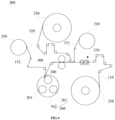
FIG. 4 is a schematic structural illustration of the cell forming apparatus in another embodiment of the present disclosure; -
FIG. 5 is a schematic structural illustration of a pole piece processing apparatus in the cell forming apparatus shown inFIG. 4 ; -
FIG. 6 is a partial top view of a cathode pole piece after processed by the pole piece processing apparatus shown inFIG. 5 ; -
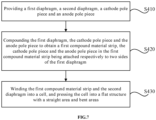
FIG. 7 is a flow diagram of a cell forming process in a preferred embodiment of the present disclosure. - In order to make the above objects, features and advantages of the present disclosure more prominent and easily understood, specific embodiments of the present disclosure will be described in detail below with reference to the accompanying drawings. In a following description, numerous specific details are set forth in order to provide a thorough understanding of the present disclosure. However, the present disclosure may be implemented in many other ways different from those described here, and those skilled in the art can make similar improvements without violating a connotation of the present disclosure. Therefore, the present disclosure is not limited by the specific embodiments disclosed below.
- In the description of the present disclosure, it should be understood that, an orientation or positional relationship indicated by terms "center", "longitudinal", "lateral", "length", "width", "thickness", "upper", "lower", "front", "back", "left", "right", "vertical", "horizontal", "top", "bottom", inner", "outer", "clockwise", "counterclockwise", "axial", "radial", "circumferential" is based on the orientation or positional relationship shown in the accompanying drawings, and is only for convenience of describing the present disclosure and simplifying the description, rather than indicating or implying that a device or element referred to must be provided with a particular orientation, be constructed and operate in a particular orientation, and therefore should not be understood as a limitation to the present disclosure.
- In addition, terms "first" and "second" are only used for descriptive purposes and should not be understood as indicating or implying relative importance or implying a number of indicated technical features. Therefore, a feature delimited with "first", "second" may expressly or implicitly comprise at least one of those features. In a description of the present disclosure, "a plurality" means at least two, such as two, three, etc., unless expressly and specifically defined otherwise.
- In the present disclosure, unless expressly specified and limited otherwise, terms "installed", "communicated", "connected", "fixed" and other terms should be interpreted in a broad sense, for example, it may be a fixed connection, a detachable connection, or an integrated; it may be a mechanical connection or an electrical connection; it may be directly connected, or indirectly connected through an intermediate medium, and it may be an internal communication between two elements or an interaction relationship between the two elements, unless otherwise explicitly defined. For those of ordinary skill in the art, specific meanings of the above terms in the present disclosure may be understood according to specific situations.
- In the present disclosure, unless expressly stated and defined otherwise, a first feature "on" or "under" a second feature may be that the first feature is in direct contact with the second feature, or the first feature and the second feature are indirectly contacted through an intermediary. In addition, the first feature being "above", "over" and "on" the second feature may mean that the first feature is directly above or obliquely above the second feature, or simply means that the first feature is higher than the second feature in a horizontal direction. The first feature being "below", "under" and "below" the second feature may mean that the first feature is directly below or obliquely below the second feature, or simply means that the first feature is smaller than the second feature in a horizontal direction.
- It should be noted that when an element is referred to as being "fixed to" or "arranged on" another element, it may be directly on another element, or there may be an intervening element therebetween. When an element is referred to as being "connected" to another element, it may be directly connected to another element or intervening elements may also be present. Terms "vertical", "horizontal", "upper", "lower", "left", "right" and similar expressions used here are only for illustration purposes rather than indicating the only implementation.
- Referring to
FIGS. 1 and2 , the present disclosure provides acell 100 and acell forming apparatus 200, wherein thecell 100 may be manufactured by thecell forming apparatus 200. Thecell 100 comprises acathode pole piece 110, ananode pole piece 120, and adiaphragm 130, and thediaphragm 130 is located between the adjacentcathode pole piece 110 andanode pole piece 120 and is used for separating them to prevent short-circuiting. Thecathode pole piece 110, theanode pole piece 120, and thediaphragm 130 are stacked and then wound and pressed to form a flat structure. - Further, the
cell 100 has astraight area 101 andbent areas 102 at both ends of thestraight area 101. Thestraight area 101 refers to an area with a parallel structure in thecell 100 with the flat structure, that is, thecathode pole piece 110, theanode pole piece 120, and thediaphragm 130 in thestraight area 101 are essentially parallel to each other, and the surfaces of each layer of thecathode pole piece 110,anode pole piece 120, anddiaphragm 130 in thestraight area 101 are substantially flat surfaces. Thebent area 102 refers to an area with a bent structure in thecell 100 with the flat structure, that is, thecathode pole piece 110, theanode pole piece 120, and thediaphragm 130 in thebent area 102 are all bent, and the surfaces of each layer of thecathode pole piece 110, theanode pole piece 120, and thediaphragm 130 are curved surfaces. - Referring again to
FIG. 1 , in a preferred embodiment of the present disclosure, thecell forming apparatus 200 comprises a first diaphragm-unwindingdevice 210, a cathode-unwindingdevice 220, an anode-unwindingdevice 230, acompounding device 240, a second diaphragm-unwindingdevice 250, and a windingdevice 260. - The first diaphragm-unwinding
device 210 is used for unwinding thefirst diaphragm 131. To facilitate subsequent compounding operations, the surface of thefirst diaphragm 131 is pre-coated with glue or other adhesives. The second diaphragm-unwindingdevice 250 is used for unwinding thesecond diaphragm 132. Wherein, thefirst diaphragm 131 and thesecond diaphragm 132 both refer to thediaphragm 130 in thecell 100. To distinguish them, the diaphragms unwound by the first diaphragm-unwindingdevice 210 and those unwound by the second diaphragm-unwindingdevice 250 are respectively referred to as thefirst diaphragm 131 and thesecond diaphragm 132, respectively. Both thefirst diaphragm 131 and thesecond diaphragm 132 are insulating films that serve to prevent short-circuiting. The first diaphragm-unwindingdevice 210 and the second diaphragm-unwindingdevice 250 are generally identical in construction and may take the form of an unwinding shaft. - The cathode-unwinding
device 220 and the anode-unwindingdevice 230 are capable of unwinding thecathode pole piece 110 and theanode pole piece 120 respectively on two sides of thefirst diaphragm 131. Both the cathode-unwindingdevice 220 and the anode-unwindingdevice 230 may take the form of an unwinding shaft, and thecathode pole piece 110 and theanode pole piece 120 may be wound on the cathode-unwindingdevice 220 and the anode-unwindingdevice 230 in the form of material strips for continuous unwinding. - After unwinding, the
first diaphragm 131 is sandwiched between thecathode pole piece 110 and theanode pole piece 120. Specifically, thecathode pole piece 110 is located beneath thefirst diaphragm 131, while theanode pole piece 120 is located above thefirst diaphragm 131. Obviously, the positions of thecathode pole piece 110 and theanode pole piece 120 may be interchanged. - The
compounding device 240 may receive thefirst diaphragm 131, thecathode pole piece 110 and theanode pole piece 120, and compound them to obtain the firstcompound material strip 300. The firstcompound material strip 300 comprises thefirst diaphragm 131 as well as thecathode pole piece 110 and theanode pole piece 120 attached on a respective one of two sides of thefirst diaphragm 131 respectively. Specifically, in the present embodiment, thecompounding device 240 comprises an upper pressure roller (not labeled in the figure) and a lower pressure roller (not labeled in the figure), between which thecathode pole piece 110,anode pole piece 120, and thefirst diaphragm 131 may pass. - The upper pressure roller and the lower pressure roller are both rotatable on their respective own axes, and one of them is connected to a driving assembly for active rotation. When the
first diaphragm 131, thecathode pole piece 110, and theanode pole piece 120 pass between the upper pressure roller and the lower pressure roller, the upper pressure roller and the lower pressure roller cooperate to clamp thefirst diaphragm 131, thecathode pole piece 110, and theanode pole piece 120. Moreover, as the upper pressure roller and the lower pressure roller rotate, thefirst diaphragm 131, thecathode pole piece 110, and theanode pole piece 120 are compounded to obtain the firstcompound material strip 300, and the obtained firstcompound material strip 300 may be transported downstream under driving of thecompounding device 240. - Wherein, the upper pressure roller and the lower pressure roller may both be heating pressure rollers to form the first
compound material strip 300 by hot pressing. Obviously, in other embodiments, the firstcompound material strip 300 may also be formed by cold pressing. - During the compounding process, since the
anode pole piece 120 and thecathode pole piece 110 are respectively located on two sides of thefirst diaphragm 131 respectively, the surfaces on both sides of thefirst diaphragm 131 will not come into direct contact with thecompounding device 240. This avoids the adhesive on the surface of thefirst diaphragm 131 from adhering to thecompounding device 240, thereby improving the compounding effect of thefirst diaphragm 131 with theanode pole piece 120 and thecathode pole piece 110. - The winding
device 260 comprises a windingneedle structure 261. Wherein, the windingneedle structure 261 may wind the firstcompound material strip 300 and thesecond diaphragm 132 into thecell 100. Thewound cell 100 is roughly cylindrical or oval in shape and may be pressed into the flat structure, which flat structure comprises thestraight area 101 and thebent area 102. - In the present embodiment, the winding
device 260 further comprises aturret 262 where a plurality of windingneedle structures 261 are provided, and theturret 262 rotates to drive the plurality of windingneedle structures 261 to sequentially transfer to a position capable of obtaining the firstcompound material strip 300 and thesecond diaphragm 132. - The
turret 262 may be connected to a driving mechanism such as a motor and may rotate by a certain angle under the drive of the driving mechanism. After theprevious cell 100 is wound, theturret 262 rotates and brings the next windingneedle structure 261 to the winding station (i.e., a position where the firstcompound material strip 300 and thesecond diaphragm 132 may be obtained). Then, the next windingneedle structure 261 extends out and obtains the firstcompound material strip 300 and thesecond diaphragm 132. Once theprevious cell 100 is cut off at the end of the material strip, the next windingneedle structure 261 may start winding for the manufacturing of thenext cell 100. In this way, the plurality of windingneedle structures 261 may alternately enter the winding station and wind the cell, thereby accelerating the production pace to reduce waiting time, and thus improving production efficiency. - The
cathode pole piece 110 is coated with a positive electrode active substance layer formed from lithium manganate, lithium cobaltate, lithium iron phosphate, etc., while theanode pole piece 120 is coated with a negative electrode active substance layer formed from graphite, silicon, etc. The applicant has found that thecathode pole piece 110 and theanode pole piece 120 located in thebent area 102 are prone to dislodge their respective active substances during bending, referred to as "powdering off'. Especially the dislodgment of the negative electrode active substance on theanode pole piece 120 may cause that the lithium intercalation sites of the negative electrode active substance layer of theanode pole piece 120 are less than the number of lithium ions that can be provided by the positive electrode active substance layer of thecathode pole piece 110 adjacent thereto, and thus that the lithium ions de-intercalated from the positive electrode active substance layer will not be able to be intercalated in equal amounts in the negative electrode active substance layer. As a result, lithium precipitation tends to occur in thebent area 102 of thecell 100 during charging of the battery. - Correspondingly, since the
cathode pole piece 110 and theanode pole piece 120 in thestraight area 101 do not need to be bent in the forming process of thecell 100 and hardly experience "powdering off', the lithium intercalation sites in the negative electrode active substance layer of theanode pole piece 120 in thestraight area 101 may be well-matched with the number of lithium ions that can be provided by the positive electrode active substance layer of thecathode pole piece 110 adjacent thereto. Therefore, thestraight area 101 of thecell 100 is generally free from the lithium precipitation phenomenon. - To solve the problem of lithium precipitation, please also refer to
FIG. 3 , in the present embodiment, thecell forming apparatus 200 further comprises a polepiece processing apparatus 270, which is capable of processing thecathode pole piece 110 to form abroken portion 103 on thecathode pole piece 110 of the firstcompound material strip 300. Thebroken portion 103 extends in a width direction of thecathode pole piece 110 and may cut off thecathode pole piece 110. It can be seen that there is no positive electrode active substance in the area where thebroken portion 103 is located. - Further, the
broken portion 103 of thecathode pole piece 110 is located in thebent area 102 of the manufacturedcell 100. Since there is no positive electrode active substance in the area where thebroken portion 103 is located, the number of lithium ions that may be de-intercalated from thecathode pole piece 110 located in thebent area 102 will be significantly reduced. It can be seen that even if the adjacentanode pole pieces 120 experience "powdering off' in the process of bending, since the number of the lithium ions that may be de-intercalated from thecathode pole piece 110 is also reduced, it is still possible to prevent the number of lithium intercalation sites of the negative electrode active substance layer of theanode pole piece 120 from being far less than the number of lithium ions that can be provided by the positive electrode active substance layer of thecathode pole piece 110 adjacent thereto, thereby reducing or avoiding the occurrence of lithium precipitation phenomenon. - In the present embodiment, the pole
piece processing apparatus 270 comprises a holding-transportingmechanism 271 and acutting mechanism 272, which are both provided between the cathode-unwindingdevice 220 and thecompounding device 240. - The holding-transporting
mechanism 271 is capable of clamping and transporting thecathode pole piece 110, thecutting mechanism 272 is capable of cutting off thecathode pole piece 110 between the holding-transportingmechanism 271 and thecompounding device 240, and the holding-transportingmechanism 271 is capable of pulling apart at a cut-off position to form thebroken portion 103. - Specifically, the holding-transporting
mechanism 271 may pull apart at the cut-off position by regulating the transporting speed. The continuous cathode pole piece material strip first passes through the holding-transportingmechanism 271 and thecutting mechanism 272 before entering thecompounding device 240. After thecathode pole piece 110 is cut off by thecutting mechanism 272, thecathode pole piece 110 located downstream of the cut-off portion is compounded with thefirst diaphragm 131 in thecompounding device 240, and the obtained firstcompound material strip 300 may be driven by thecompounding device 240 to maintain a uniform transporting speed; at this time, the holding-transportingmechanism 271 decelerates or stops the transporting, so that the cut-off portion of thecathode pole piece 110 is pulled apart until thebroken portion 103 is formed. Next, the holding-transportingmechanism 271 is regulated in speed to be synchronized with thecompounding device 240, and assists thecompounding device 240 in driving the firstcompound material strip 300 to be further transported downstream while feeding thecathode pole piece 110 located upstream of the cut-off portion into thecompounding device 240. - Further, in the present embodiment, the holding-transporting
mechanism 271 comprises clamping plates, which are capable of reciprocating movement along the transporting direction of thecathode pole piece 110. After thecathode pole piece 110 is cut off, the clamping plates may clamp thecathode pole piece 110 located upstream of the cut-off portion and move along with thecathode pole piece 110. In this way, it is possible to prevent the cut-offcathode pole piece 110 from sagging due to an excessively long overhang at the end, thereby ensuring that thecathode pole piece 110 may smoothly enter thecompounding device 240. - It should be noted that in other embodiments, the
cutting mechanism 272 may further punch thecathode pole piece 110 by the cooperation between a male die and a female die, and may remove a certain width of waste material from thecathode pole piece 110, thereby naturally forming thebroken portion 103 while cutting thecathode pole piece 110 off. In this case, the holding-transportingmechanism 271 may maintain synchronous transporting with thecompounding device 240, without the need to change the speed of the holding-transportingmechanism 271 to pull the cut-off portion of thecathode pole piece 110 apart to form thebroken portion 103. - One or more
broken portions 103 may be formed on thecathode pole piece 110. When a plurality ofbroken portions 103 are required, the holding-transportingmechanism 271 and thecutting mechanism 272 may simply repeat the above operations. - Specifically, in the present embodiment, the pole
piece processing apparatus 270 further comprises a tape-bonding mechanism 273, which is capable of bonding afirst tape 140 on a side of thecathode pole piece 110 so as to bond, to thefirst diaphragm 131, thecathode pole piece 110 at a side of thebroken portion 103 proximate to the holding-transportingmechanism 271. - The
broken portion 103 may divide thecathode pole piece 110 into two pole piece subsections, and thecathode pole piece 110 located at a side of thebroken portion 103 proximate to the holding-transportingmechanism 271 refers to the upstream end of one of the pole piece subsections. The upstream end refers to the front end in the transporting direction of the firstcompound material strip 300, for example, if the firstcompound material strip 300 is transported from left to right, then the right end is the upstream end. Before the firstcompound material strip 300 enters the windingdevice 260, the firstcompound material strip 300 generally needs to wind around a guide roller to change direction. When winding around the guide roller, the upstream end of the pole piece subsection is prone to upwarping and detaching from thefirst diaphragm 131. Since thefirst tape 140 may bond the upstream end of the pole piece subsection to thefirst diaphragm 131, thecathode pole piece 110 will not detach from thefirst diaphragm 131 when the firstcompound material strip 300 winds around the guide roller. - As shown in
FIG. 3 , a portion of the firstadhesive tape 140 passes through thebroken portion 103 to be bonded to thefirst diaphragm 131, and another portion of the firstadhesive tape 140 is bonded to thecathode pole piece 110. The firstadhesive tape 140 may be bonded before or after thecathode pole piece 110 being compounded with thefirst diaphragm 131. - Further, in the present embodiment, the tape-
bonding mechanism 273 is provided between thecutting mechanism 272 and thecompounding device 240. That is, the tape-bonding mechanism 273 completes the tape-bonding before thecathode pole piece 110 being compounded with thefirst diaphragm 131. Therefore, during the three-in-one compound of thecathode pole piece 110, theanode pole piece 120, and thefirst diaphragm 131 by thecompounding device 240, the firstadhesive tape 140 may also prevent thecathode pole piece 110 and thefirst diaphragm 131 from being misaligned. - Further, in the present embodiment, the tape-
bonding mechanism 273 is further capable of bonding a second tape (not shown in the figure) on a side of thecathode pole piece 110 so as to bond, to thefirst diaphragm 131, thecathode pole piece 110 at a side of thebroken portion 103 distal to the holding-transportingmechanism 271. - As described above, the
broken portion 103 may divide thecathode pole piece 110 into the two pole piece subsections, and thecathode pole piece 110 at a side of thebroken portion 103 distal to the holding-transporting mechanism 221 refers to the downstream end of one of the pole piece subsections. The downstream end refers to the rear end in the transporting direction of the firstcompound material strip 300, for example, if the firstcompound material strip 300 is transported from left to right, then the left end is the downstream end. After the downstream end of the pole piece subsection is bonded to thefirst diaphragm 131 by the second tape, it is possible to prevent thecathode pole piece 110 from deviating with respect to thefirst diaphragm 131 during transporting, which is advantageous in improving the quality of thecell 100. - Obviously, in order to form the
broken portion 103 on thecathode pole piece 110 of the firstcompound material strip 300, the polepiece processing apparatus 270 may also take other forms. For example, referring toFIGS. 4 and5 , in another embodiment, the polepiece processing apparatus 270 comprises a holding-transportingmechanism 274, acutting mechanism 275 and a tape-bonding mechanism 276. - There are at least two holding-transporting
mechanisms 274, and each holding-transportingmechanism 274 is capable of holding and transporting thecathode pole piece 110. Thecutting mechanism 275 is provided between two adjacent holding-transportingmechanisms 274, and eachcutting mechanism 275 may cut off thecathode pole piece 110, so as to obtain at least two pole piece subsections. At least two pole piece subsections may be held by different holding-transportingmechanisms 274 and transported in the transporting direction. Furthermore, the at least two holding-transportingmechanisms 274 are capable of driving the pole piece subsection being held to be transported different distances in the transporting direction, such that thebroken portion 103 is formed between the adjacent two pole piece subsections. Specifically, the different holding-transportingmechanisms 274 may form a speed difference therebetween, so that the pole piece subsections held by the different holding-transportingmechanisms 274 are pulled apart to form thebroken portions 103. - It should be noted that in other embodiments, the
cutting mechanism 275 may also punch thecathode pole piece 110 by the cooperation between a male die and a female die, and may cut off a certain width of waste material from thecathode pole piece 110, thereby naturally forming thebroken portion 103 while cutting thecathode pole piece 110 off. In this way, each holding-transportingmechanism 274 may maintain a uniform velocity without the need to pull the pole piece subsections apart by the holding-transportingmechanism 274. - Specifically, in the present embodiment, each holding-transporting
mechanism 274 comprises a clamping roller, and the rotational speed of the clamping roller of each holding-transportingmechanism 274 may be adjusted individually. By adjusting the rotational speed of the clamping roller, it is possible to adjust the transporting speed of each holding-transportingmechanism 274. In this way, it is possible to create a velocity difference between the different holding-transportingmechanisms 274, so as to pull apart the respective pole piece subsections they are clamping to form thebroken portion 103. The clamping roller may be adjusted more easily, takes up less space, and contributes to the compactness of the holding-transportingmechanism 274. - Specifically, in the present embodiment, there are provided three holding-transporting
mechanisms 274 and two cuttingmechanisms 275, with acutting mechanism 275 provided between each pair of adjacent holding-transportingmechanisms 274. After thecathode pole piece 110 is processed by the polepiece processing apparatus 200, it is possible to form twobroken portions 103 and obtain three pole piece subsections, each of the pole piece subsections is held by the holding-transportingmechanism 274. - Please also refer to
FIG. 6 , the tape-bonding mechanism 276 may bond theconnector 150 to at least one side of thecathode pole piece 110 to cover thebroken portion 103, so as to integrally connect at least two pole piece subsections. The tape-bonding mechanism 276 is also provided between two adjacent holding-transportingmechanisms 274. The tape-bonding mechanism 276 is provided in pairs with thecutting mechanism 275. More specifically, the tape-bonding mechanism 276 is located downstream of thecutting mechanism 275 with which it is paired. - In the present embodiment, the
connector 150 may be a tape, and the tape-bonding mechanism 276 bonds tapes on both sides of thecathode pole piece 110 to enhance reliability. - The working process of the pole
piece processing apparatus 270 is described below with reference to the drawings. - For ease of description in the following, the three holding-transporting
mechanisms 274 from the upstream end to downstream end (from right to left inFigure 5 ) of the transporting direction of thecathode pole piece 110, are respectively referred to as the first, second, and third holding-transportingmechanisms 274; the two cuttingmechanisms 275 are respectively referred to as thefirst cutting mechanism 275 and thesecond cutting mechanism 275; the two tape-bonding mechanisms 276 are respectively referred to as the first tape-bonding mechanisms 276 and the second tape-bonding mechanism 276; the obtained three pole piece subsections are respectively referred to as the first pole piece subsection, the second pole piece subsection, and the third pole piece subsection. - After the
cathode pole piece 110 enters the polepiece processing apparatus 270, thefirst cutting mechanism 275 in the pole piece transporting direction cuts off thecathode pole piece 110 between the first and second holding-transportingmechanisms 274, and thesecond cutting mechanism 275 cuts off thecathode pole piece 110 between the second and third holding-transportingmechanisms 274, resulting in three pole piece subsections; the first, second, and third holding-transportingmechanisms 274 hold the pole piece subsections and transport them downstream respectively. Wherein, the transporting speed of the first holding-transportingmechanism 274 is less than that of the second holding-transportingmechanism 274, and the transporting speed of the second holding-transportingmechanism 274 is less than that of the third holding-transportingmechanism 274. Consequently, the first pole piece subsection moves a shorter distance downstream than the second pole piece subsection, and the second holding-transporting mechanism moves a shorter distance than the third holding-transporting mechanism. In this way, the three pole piece subsections are pulled apart so as to form twobroken portions 103. - Further, after the
broken portions 103 is formed, the two tape-bonding mechanisms 276 are provided withconnectors 150 on both sides of the twobroken portions 103 respectively, such as by applying adhesive tapes. Specifically, the first tape-bonding mechanism 276 applies a tape to bond the first pole piece subsection to the second pole piece subsection, and the second tape-bonding mechanism 276 applies a tape to bond the second pole piece subsection to the third pole piece subsection, thus integrally connecting the three pole piece subsections. - In this way, after forming the
broken portion 103 on thecathode pole piece 110, connecting the both sides of thebroken portion 103 by means of theconnector 150 ensures the continuity of thecathode pole piece 110, allowing thecathode pole piece 110 to smoothly enter thecompounding device 240 and be compounded with thefirst diaphragm 131 andanode pole piece 120. - Regarding the above
cell forming apparatus 200, before theanode pole piece 120 andcathode pole piece 110 enter the windingdevice 260, firstly thecompounding device 240 compounds theanode pole piece 120 and thecathode pole piece 110 with thefirst diaphragm 131 in a three-in-one compound to obtain the firstcompound material strip 300. Since theanode pole piece 120 and thecathode pole piece 110 are respectively located on two sides of thefirst diaphragm 131, thefirst diaphragm 131 will be enveloped between theanode pole piece 120 and thecathode pole piece 110. During the compounding process, the surfaces on both sides of thefirst diaphragm 131 will not come into direct contact with thecompounding device 240. Therefore, it is possible to prevent the adhesive on the surface of thefirst diaphragm 131 from adhering to thecompounding device 240, thereby improving the compounding effect of thefirst diaphragm 131 with theanode pole piece 120 and thecathode pole piece 110, and thus enhancing the quality of the manufactured cell. - Please also refer to
FIG. 7 , the present disclosure further provides a cell forming process, which may be performed by thecell forming apparatus 200. The cell forming process comprises steps S410 to S430: - Step S410: providing a
first diaphragm 131, asecond diaphragm 132, acathode pole piece 110 and ananode pole piece 120. Specifically, thefirst diaphragm 131, thesecond diaphragm 132, thecathode pole piece 110, and theanode pole piece 120 may be continuously unwound in the form of an unwinding shaft. - Step S420: compounding the
first diaphragm 131, adjacentcathode pole piece 110 andanode pole piece 120 to obtain a firstcompound material strip 300, adjacentcathode pole piece 110 andanode pole piece 120 in the firstcompound material strip 300 being attached respectively to two sides of thefirst diaphragm 131. - During the compounding process, the
cathode pole piece 110 and theanode pole piece 120 are respectively located on two sides of thefirst diaphragm 131 respectively, and are capable of enveloping thefirst diaphragm 131. As a result, the surfaces on both sides of thefirst diaphragm 131 will not come into direct contact with the compounding device, thereby preventing the adhesive on the surfaces of thefirst diaphragm 131 from adhering to the compounding device, and thus improving the compounding effect between thefirst diaphragm 131, theanode pole piece 120, and thecathode pole piece 110. - Step S430: winding the first
compound material strip 300 and thesecond diaphragm 132 into a cell, and pressing the cell into a flat structure with a straight area and a bent area. - The specific structure of the
cell 100 and the definitions of thestraight area 101 and thebent area 102 have been described in detail in the foregoing, and thus are not further elaborated herein. - Since the compounding effect of the
first diaphragm 131 with theanode pole piece 120 and thecathode pole piece 110 is significantly improved, the quality of the manufacturedcell 100 may also be improved. It should be noted that since the manufacturing process of thecell 100 is continuous, the steps S410 to S430 may be performed simultaneously. - In the present embodiment, the cell forming process further comprises a step of: processing the
cathode pole piece 110 to form abroken portion 103 on thecathode pole piece 110 of the firstcompound material strip 300, thebroken portion 103 being located in the bent area. - As described above, since there is no positive electrode active substance in the area where the
broken portion 103 is located, the number of lithium ions that may be de-intercalated from thecathode pole piece 110 located in thebent area 102 will be significantly reduced, thereby reducing or avoiding the occurrence of lithium precipitation phenomenon. - The technical features of the above embodiments may be combined arbitrarily. For the sake of brevity, not all possible combinations of the individual technical features of the above embodiments are described. However, a combination of these technical features shall be considered to be within the scope of the present specification, as long as there is no contradiction in the combination.
- The above embodiments are merely expressions of a few implementations of the present disclosure described in a specific and detailed manner, and are not to be construed as limitation to the scope of the present disclosure. It is to be noted that for a person of ordinary skill in the art, various modifications and improvements could be made without departing from the principle of the present disclosure, and shall fall into the protection scope of the present disclosure. Therefore, the protection scope of the present disclosure shall be subject to the appended claims.
Claims (15)
- A cell forming apparatus, characterized by comprising a first diaphragm-unwinding device, a cathode-unwinding device, an anode-unwinding device, a compounding device, a second diaphragm-unwinding device and a winding device; the first diaphragm-unwinding device is configured for unwinding a first diaphragm, and the cathode-unwinding device and the anode-unwinding device are capable of unwinding a cathode pole piece and an anode pole piece respectively on two sides of the first diaphragm; the compounding device is capable of receiving the first diaphragm, the cathode pole piece and the anode pole piece and compounding them to obtain a first compound material strip; the second diaphragm-unwinding device is configured for unwinding a second diaphragm; the winding device comprises a winding needle structure capable of winding the first compound material strip and the second diaphragm into a cell.
- The cell forming apparatus according to claim 1, wherein the compounding device comprises an upper pressure roller and a lower pressure roller, and wherein the cathode pole piece, the anode pole piece, and the first diaphragm are capable of passing between the upper pressure roller and the lower pressure roller.
- The cell forming apparatus according to claim 2, wherein both the upper pressure roller and the lower pressure roller are heat pressure rollers.
- The cell forming apparatus according to claim 1, wherein the cell is capable of being pressed into a flat structure with a straight area and a bent area, the cell forming apparatus further comprises a pole piece processing apparatus, which is capable of processing the cathode pole piece to form a broken portion on the cathode pole piece of the first compound material strip, and the broken portion is located in the bent area of the manufactured cell.
- The cell forming apparatus according to claim 4, wherein the pole piece processing apparatus comprises a holding-transporting mechanism and a cutting mechanism, which are both provided between the cathode-unwinding device and the compounding device, the holding-transporting mechanism is capable of clamping and transporting the cathode pole piece, the cutting mechanism is capable of cutting off the cathode pole piece between the holding-transporting mechanism and the compounding device, and the holding-transporting mechanism is capable of pulling apart at a cut-off position to form the broken portion.
- The cell forming apparatus according to claim 5, wherein the pole piece processing apparatus further comprises a tape-bonding mechanism, which is capable of bonding a first tape on a side of the cathode pole piece so as to bond, to the first diaphragm, the cathode pole piece at a side of the broken portion proximate to the holding-transporting mechanism.
- The cell forming apparatus according to claim 6, wherein the tape-bonding mechanism is further capable of bonding a second tape on a side of the cathode pole piece so as to bond, to the first diaphragm, the cathode pole piece at a side of the broken portion distal to the holding-transporting mechanism.
- The cell forming apparatus according to claim 6 or 7, wherein the tape-bonding mechanism is provided between the cutting mechanism and the compounding device.
- The cell forming apparatus according to claim 4, wherein the pole piece processing apparatus comprises:at least two holding-transporting mechanisms, each of which is capable of holding and transporting the cathode pole piece;a cutting mechanism provided between two adjacent holding-transporting mechanisms, each cutting mechanism being capable of cutting off the cathode pole piece so as to obtain at least two pole piece subsections, and the at least two holding-transporting mechanisms being capable of holding the at least two pole piece subsections respectively and pulling the two adjacent pole piece subsections apart to form the broken portion;a tape-bonding mechanism, which is capable of bonding a connector on at least one side of the cathode pole piece, to cover the broken portion so as to integrally connect the at least two pole piece subsections.
- The cell forming apparatus according to claim 1, wherein the winding device further comprises a turret where a plurality of winding needle structures are provided, and the turret rotates to drive the plurality of winding needle structures to sequentially transfer to a position capable of obtaining the first compound material strip and the second diaphragm.
- A cell forming process, characterized by comprising steps of:providing a first diaphragm, a second diaphragm, a cathode pole piece and an anode pole piece;compounding the first diaphragm, the cathode pole piece and the anode pole piece to obtain a first compound material strip, the cathode pole piece and the anode pole piece in the first compound material strip being attached respectively to two sides of the first diaphragm; andwinding the first compound material strip and the second diaphragm into a cell, and pressing the cell into a flat structure with a straight area and a bent area.
- The cell forming process according to claim 11, characterized by further comprising a step of: processing the cathode pole piece to form a broken portion on the cathode pole piece of the first compound material strip, the broken portion being located in the bent area.
- A cell, wherein the cell is manufactured by the cell forming apparatus according to any one of claims 1 to 10; or, the cell is manufactured by the cell forming process according to claim 11 or 12, the cell comprises a cathode pole piece, an anode pole piece, and a diaphragm located between a cathode pole piece and an anode pole piece adjacent thereto, wherein the cathode pole piece, the anode pole piece and the diaphragm are wound and pressed to form a flat structure, and the cell has a straight area and bent areas located at both ends of the straight area.
- The cell according to claim 13, wherein the cathode pole piece, at least partially located in the bent area, forms a broken portion extending in a width direction.
- The cell according to claim 14, wherein the broken portion divides the cathode pole piece where the broken portion is located into at least two pole piece subsections, and the at least two pole piece subsections are integrally connected through a connector.
Applications Claiming Priority (2)
| Application Number | Priority Date | Filing Date | Title |
|---|---|---|---|
| CN202210195515.6A CN114759270A (en) | 2022-03-01 | 2022-03-01 | Battery cell forming equipment, battery cell forming process and battery cell |
| PCT/CN2023/072042 WO2023165278A1 (en) | 2022-03-01 | 2023-01-13 | Cell forming apparatus, cell forming process, and cell |
Publications (2)
| Publication Number | Publication Date |
|---|---|
| EP4465408A1 true EP4465408A1 (en) | 2024-11-20 |
| EP4465408A4 EP4465408A4 (en) | 2026-04-22 |
Family
ID=82324775
Family Applications (1)
| Application Number | Title | Priority Date | Filing Date |
|---|---|---|---|
| EP23762679.1A Pending EP4465408A4 (en) | 2022-03-01 | 2023-01-13 | CELL FORMATION DEVICE, CELL FORMATION PROCESS AND CELL |
Country Status (4)
| Country | Link |
|---|---|
| US (1) | US20240413376A1 (en) |
| EP (1) | EP4465408A4 (en) |
| CN (1) | CN114759270A (en) |
| WO (1) | WO2023165278A1 (en) |
Families Citing this family (9)
| Publication number | Priority date | Publication date | Assignee | Title |
|---|---|---|---|---|
| CN114759270A (en) * | 2022-03-01 | 2022-07-15 | 无锡先导智能装备股份有限公司 | Battery cell forming equipment, battery cell forming process and battery cell |
| CN115159213B (en) * | 2022-08-23 | 2022-12-06 | 江苏时代新能源科技有限公司 | Electrode Assembly Manufacturing Equipment |
| CN116613369B (en) * | 2023-07-21 | 2024-03-01 | 深圳海辰储能控制技术有限公司 | Electrode assembly and cell head winding method |
| CN116632317B (en) * | 2023-07-21 | 2024-01-26 | 深圳海辰储能控制技术有限公司 | Battery core winding equipment and battery core winding method |
| WO2025148306A1 (en) * | 2024-01-11 | 2025-07-17 | 宁德时代新能源科技股份有限公司 | Winding device and battery manufacturing device |
| WO2025232028A1 (en) * | 2024-05-07 | 2025-11-13 | 宁德时代新能源科技股份有限公司 | Winding device and method for producing battery cells |
| CN118472419B (en) * | 2024-07-12 | 2024-09-13 | 安仁亿等新能源研究院有限公司 | A battery winding device and a battery winding production detection method |
| CN118763294B (en) * | 2024-09-06 | 2025-01-10 | 宁德时代新能源科技股份有限公司 | Cell molding method and battery manufacturing method |
| CN119447710B (en) * | 2025-01-09 | 2025-08-26 | 宁德时代新能源科技股份有限公司 | Battery monomer, composite pole piece preparation device and method, battery device and energy storage device |
Family Cites Families (15)
| Publication number | Priority date | Publication date | Assignee | Title |
|---|---|---|---|---|
| US6461759B1 (en) * | 2000-06-09 | 2002-10-08 | Wilson Greatbatch, Ltd. | Cathode assembly with bare current collector regions to facilitate winding |
| JP2004288837A (en) * | 2003-03-20 | 2004-10-14 | Jelmax Co Ltd | Electrolytic capacitor and fuel cell driven vehicle using same |
| CN101901934B (en) * | 2010-07-22 | 2012-07-04 | 黄祥盛 | Coiled laminate square lithium-ion battery cell and preparation method thereof |
| KR101579575B1 (en) * | 2013-06-18 | 2015-12-22 | 주식회사 엘지화학 | Lithium secondary battery with improved life and safety |
| CN106099163B (en) * | 2016-08-12 | 2019-07-12 | 无锡先导智能装备股份有限公司 | Protect adhesive tape cutting and transfer device |
| CN207834493U (en) * | 2017-11-03 | 2018-09-07 | 深圳市诚捷智能装备股份有限公司 | Full-automatic lithium battery cell winding machine |
| CN207800790U (en) * | 2017-12-21 | 2018-08-31 | 佛山市金银河智能装备股份有限公司 | A kind of pole piece cut-out tape sticking device of up- coiler |
| CN109830738B (en) * | 2019-03-29 | 2024-07-02 | 无锡先导智能装备股份有限公司 | Battery core winding device |
| CN209947961U (en) * | 2019-06-12 | 2020-01-14 | 新余赣锋电子有限公司 | Can prevent cracked electric core of pole piece |
| KR102848290B1 (en) * | 2019-07-16 | 2025-08-20 | 삼성전자주식회사 | Battery and electronic device having the same |
| CN213692108U (en) * | 2020-10-27 | 2021-07-13 | 宁德时代新能源科技股份有限公司 | Electrode assembly, battery cell, battery, and power consumption device |
| CN214254489U (en) * | 2020-12-18 | 2021-09-21 | 宁德时代新能源科技股份有限公司 | Electrode assembly, battery cell, battery and power consumption device |
| CN214588948U (en) * | 2021-04-21 | 2021-11-02 | 东莞市雅康精密机械有限公司 | Composite forming device for simultaneously clamping and feeding cathode and anode sheets into sheet |
| CN114759270A (en) * | 2022-03-01 | 2022-07-15 | 无锡先导智能装备股份有限公司 | Battery cell forming equipment, battery cell forming process and battery cell |
| CN217740729U (en) * | 2022-03-01 | 2022-11-04 | 无锡先导智能装备股份有限公司 | Battery core forming equipment and battery core |
-
2022
- 2022-03-01 CN CN202210195515.6A patent/CN114759270A/en active Pending
-
2023
- 2023-01-13 EP EP23762679.1A patent/EP4465408A4/en active Pending
- 2023-01-13 WO PCT/CN2023/072042 patent/WO2023165278A1/en not_active Ceased
-
2024
- 2024-08-23 US US18/813,634 patent/US20240413376A1/en active Pending
Also Published As
| Publication number | Publication date |
|---|---|
| WO2023165278A1 (en) | 2023-09-07 |
| US20240413376A1 (en) | 2024-12-12 |
| EP4465408A4 (en) | 2026-04-22 |
| CN114759270A (en) | 2022-07-15 |
Similar Documents
| Publication | Publication Date | Title |
|---|---|---|
| EP4465408A1 (en) | Cell forming apparatus, cell forming process, and cell | |
| CN113302777B (en) | Electrode assembly, molding method and production system thereof, secondary battery, battery module and device | |
| CN110459796B (en) | A preparation method of laminated electric core, laminated electric core, lamination device and system | |
| CN102971888B (en) | Continuous prismatic cell stacking system and method | |
| CN216750029U (en) | Winding equipment | |
| CN218039357U (en) | Battery cell manufacturing equipment | |
| CN108352492B (en) | Secondary battery cells | |
| CN216750028U (en) | a winding device | |
| CN110247124A (en) | A kind of lithium ion battery high speed laminating method, lamination device and lithium ion battery | |
| JP2012513076A (en) | Secondary battery manufacturing method and secondary battery | |
| CN204946995U (en) | Secondary cell battery core and coiling and molding system thereof | |
| US20160013468A1 (en) | Method of manufacturing electrode assembly | |
| CN218333856U (en) | Battery cell, battery and battery cell manufacturing equipment | |
| CN109361011B (en) | Winding type lithium ion battery cell and preparation method thereof | |
| CN103490089A (en) | Electrode subassembly, preparation method thereof and lithium secondary battery | |
| US20240421360A1 (en) | Cell, battery and cell manufacturing apparatus | |
| CN117790876B (en) | Battery cell winding equipment and method | |
| CN217740615U (en) | Battery core forming equipment and battery core | |
| CN219800980U (en) | Electrode assemblies, battery cells, batteries, electrical devices and winding devices | |
| WO2025185065A1 (en) | Adhesive tape adhering device, adhesive tape adhering method, and battery production line | |
| CN218849573U (en) | Battery cell stacking equipment | |
| CN111313104A (en) | Lithium ion battery | |
| CN217426786U (en) | Battery with a battery cell | |
| CN116864825A (en) | Method and system for manufacturing cathode continuous solid-state battery and solid-state battery | |
| CN117374407A (en) | A battery core continuous winding system and method |
Legal Events
| Date | Code | Title | Description |
|---|---|---|---|
| STAA | Information on the status of an ep patent application or granted ep patent |
Free format text: STATUS: THE INTERNATIONAL PUBLICATION HAS BEEN MADE |
|
| PUAI | Public reference made under article 153(3) epc to a published international application that has entered the european phase |
Free format text: ORIGINAL CODE: 0009012 |
|
| STAA | Information on the status of an ep patent application or granted ep patent |
Free format text: STATUS: REQUEST FOR EXAMINATION WAS MADE |
|
| 17P | Request for examination filed |
Effective date: 20240812 |
|
| AK | Designated contracting states |
Kind code of ref document: A1 Designated state(s): AL AT BE BG CH CY CZ DE DK EE ES FI FR GB GR HR HU IE IS IT LI LT LU LV MC ME MK MT NL NO PL PT RO RS SE SI SK SM TR |
|
| DAV | Request for validation of the european patent (deleted) | ||
| DAX | Request for extension of the european patent (deleted) | ||
| A4 | Supplementary search report drawn up and despatched |
Effective date: 20260320 |
|
| RIC1 | Information provided on ipc code assigned before grant |
Ipc: H01M 10/0587 20100101AFI20260316BHEP Ipc: H01M 10/0525 20100101ALI20260316BHEP Ipc: H01M 4/04 20060101ALI20260316BHEP Ipc: H01M 4/139 20100101ALI20260316BHEP Ipc: H01M 10/04 20060101ALI20260316BHEP Ipc: H01M 50/403 20210101ALI20260316BHEP |