EP4465239A1 - Verfahren und system zur verfolgung eines pixels in einem video - Google Patents
Verfahren und system zur verfolgung eines pixels in einem video Download PDFInfo
- Publication number
- EP4465239A1 EP4465239A1 EP23173791.7A EP23173791A EP4465239A1 EP 4465239 A1 EP4465239 A1 EP 4465239A1 EP 23173791 A EP23173791 A EP 23173791A EP 4465239 A1 EP4465239 A1 EP 4465239A1
- Authority
- EP
- European Patent Office
- Prior art keywords
- frame
- pixel
- current frame
- reference frame
- anchor
- Prior art date
- Legal status (The legal status is an assumption and is not a legal conclusion. Google has not performed a legal analysis and makes no representation as to the accuracy of the status listed.)
- Pending
Links
Images
Classifications
-
- G—PHYSICS
- G06—COMPUTING OR CALCULATING; COUNTING
- G06T—IMAGE DATA PROCESSING OR GENERATION, IN GENERAL
- G06T7/00—Image analysis
- G06T7/20—Analysis of motion
-
- G—PHYSICS
- G06—COMPUTING OR CALCULATING; COUNTING
- G06T—IMAGE DATA PROCESSING OR GENERATION, IN GENERAL
- G06T2207/00—Indexing scheme for image analysis or image enhancement
- G06T2207/10—Image acquisition modality
- G06T2207/10016—Video; Image sequence
-
- G—PHYSICS
- G06—COMPUTING OR CALCULATING; COUNTING
- G06T—IMAGE DATA PROCESSING OR GENERATION, IN GENERAL
- G06T2207/00—Indexing scheme for image analysis or image enhancement
- G06T2207/20—Special algorithmic details
- G06T2207/20081—Training; Learning
-
- G—PHYSICS
- G06—COMPUTING OR CALCULATING; COUNTING
- G06T—IMAGE DATA PROCESSING OR GENERATION, IN GENERAL
- G06T2207/00—Indexing scheme for image analysis or image enhancement
- G06T2207/20—Special algorithmic details
- G06T2207/20084—Artificial neural networks [ANN]
-
- G—PHYSICS
- G06—COMPUTING OR CALCULATING; COUNTING
- G06T—IMAGE DATA PROCESSING OR GENERATION, IN GENERAL
- G06T2207/00—Indexing scheme for image analysis or image enhancement
- G06T2207/30—Subject of image; Context of image processing
- G06T2207/30241—Trajectory
Definitions
- the present disclosure relates to the field of computer vision, and more particularly to a method for tracking at least one pixel from a reference frame to a current frame in a video.
- the method may find applications in all kinds of industries, including the automotive industry, video editing, motion estimation or tracking, 2D or 3D reconstruction, camera autocalibration, etc.
- Optical flow estimation is a computer vision task aiming to determine the movement of pixels throughout a video.
- Reliable dense optical flow estimation has a significant enabling potential for diverse advanced computer vision applications, including structure-from-motion, video editing, and augmented reality.
- Optical flows may be used between consecutive frames for motion estimation in videos, but this does not enable to generate consistent and dense long-range motion trajectories for the pixels.
- a simple baseline method for tracking one or more pixels (e.g. obtaining point-to-point correspondences) in a video concatenates interpolated optical flow to form trajectories of a pixel, i.e. the set of projections of the pre-image of the pixel, for all frames in a sequence.
- error accumulation leading to drift sensitivity to occlusion and non-robustness
- a single poorly estimated optical flow damages the long-term correspondences for future frames.
- concatenated optical flow between consecutive frames cannot recover trajectories after temporary occlusions.
- the object of the present invention is to at least substantially remedy the above-mentioned drawbacks.
- the present disclosure relates to a computer-implemented method for tracking at least one pixel from a reference frame to a current frame in a video comprising the reference frame, the current frame and at least one intermediate frame between the reference frame and the current frame, the at least one pixel having a known position in the reference frame, the method comprising:
- the method is referred to hereinafter as the tracking method.
- the at least one pixel comprises one pixel or a plurality of pixels.
- a”, “an”, and “the” are intended to refer to “at least one” or “each” and to include plural forms as well. Conversely, generic plural forms include the singular.
- the video includes a sequence of frames, e.g. a sequence of images, at any desired regular or irregular sampling rate.
- the reference frame is a given frame of the video which may be the first (e.g. earliest) frame of the video, the last (e.g. latest) frame of the video, or any frame in-between. The position of the pixel in the reference frame is assumed to be known.
- the current frame is another frame of the video, in which it is desired to determine the position of the pixel.
- the current frame is neither the reference frame nor adjacent the reference frame.
- the current frame may be located in the video before or after the reference frame.
- the intermediate frames may stand for all the frames between the current frame and the reference frame, or only part of them.
- the intermediate frames may comprise frames selected to potentially serve as anchor frames (apart from the reference frame).
- Tracking the pixel from the reference frame to the current frame does not mean that the tracking method needs to determine or even compute every position of the pixel in the intermediate frames, but only to determine the overall displacement of the pixel between the reference frame and the current frame.
- the tracking method estimates a plurality of position candidates for the pixel in the current frame.
- Each position candidate may be built based on a respective anchor frame among the reference frame and the intermediate frames. Specifically, for a given anchor frame, the corresponding position candidate is estimated by chaining the position of the pixel in the anchor frame and an optical flow from the anchor frame to the current frame. In other words, the position of the pixel in the current frame is derived by applying or concatenating said optical flow to the position of the pixel in the anchor frame.
- Such position candidates may be estimated for a plurality of respective anchor frames.
- the number of position candidates may be less than or equal to the number of possible anchor frames, as not all of the intermediate frames and/or reference frame may be used as anchor frames.
- the position of the pixel in the anchor frame may be estimated, e.g. if the anchor frame is an intermediate frame, or known, e.g. if the anchor frame is the reference frame.
- the optical flow from the anchor frame to the current frame may be calculated by means known per se in the art, e.g using at least one machine learning model, such as a convolutional neural network (CNN).
- CNN convolutional neural network
- the tracking method determines the position of the at least one pixel in the current frame by selecting one of the position candidates, e.g. the most likely one to represent the position of the pixel in the current frame or any suitable selection process, or by combining two or more of the position candidates, e.g. by a weighted average or any suitable combination process.
- the tracking method may take into account a single possible position for the pixel in each anchor frame. Thanks to this provision, the tracking is based on previously estimated/known positions, hence a limited number of position candidates for the current frame. The method is therefore efficient.
- the proposed tracking method is robust because, thanks to the plurality of position candidates, incorrect estimations in some intermediate frames can be ignored at a later frame (i.e. at the current frame) by choosing another position candidate. Accordingly, drift is reduced. This brings robustness to the tracking method, especially for long-term tracking.
- the position of the at least one pixel in the anchor frame is obtained by the above-described tracking method.
- the tracking method may be a recursive method.
- the obtained position of the pixel in the anchor frame is more reliable, which makes the tracking method as a whole more accurate.
- the position of the at least one pixel in a frame adjacent the reference frame is obtained by chaining the known position of the at least one pixel in the reference frame and an optical flow from the reference frame to the adjacent frame.
- the frame adjacent the reference frame is one of the intermediate frames. Thanks to these provisions, the position of the pixel in the adjacent frame can be obtained in a simple yet reliable way.
- the at least one pixel comprises a plurality of pixels.
- the estimating and determining are carried out independently for each of the at least one pixel.
- the tracking method may provide for pixel-level tracking in the video, as opposed to object- or feature-level tracking. This provides more flexibility for various applications, in particular as no object model is needed.
- the at least one pixel includes a dense selection of pixels of the video. Dense tracking of pixels in the video provides a more robust basis for various applications.
- the current frame and the intermediate frames serving as anchor frames are increasingly spaced from one another in a direction from the current frame to the reference frame.
- the tracking method sufficiently takes into account the context of the pixel temporally close to the current frame, while also keeping a connection to long-term information in more distant frames. Yet, by selecting increasingly spaced anchor frames, the tracking method remains efficient.
- the current frame and the intermediate frames serving as anchor frames are spaced from one another in a logarithmic manner.
- the tracking method further comprising evaluating respective scores of the position candidates, and determining the position of the at least one pixel in the current frame based on the respective scores.
- the scores give an objective basis for selecting one of the position candidates or combining two or more of the position candidates.
- Each position candidate may be rated with one or more score.
- the score comprises at least one of non-visibility score and an uncertainty score.
- the non-visibility score may quantify the likelihood of the at least one pixel not to be visible in the current frame or in the corresponding anchor frame, e.g. being occluded or out of view.
- the uncertainty score may quantify the uncertainty associated to the estimating of the corresponding position candidate. Thanks to these scores, the tracking method may determine the reliability of each position candidate.
- At least one of the non-visibility score and the uncertainty score is computed by a machine learning model.
- the machine learning model may comprise an artificial neural network, e.g. a CNN. Thanks to the machine learning model, the score(s) may be learnt, which makes the tracking method more generic.
- the determining comprises identifying a position candidate as a least likely position candidate if the non-visibility score of the position candidate indicates that the at least one pixel is not visible in the current frame or in the corresponding anchor frame. That is, when considering the plurality of position candidates, some of them may be discarded or given a low weight in the final determination.
- One criterion for doing so is to determine whether the position candidate corresponds to a position in which the pixel was visible in the anchor frame. If the pixel was not visible in the anchor frame (e.g. if the non-visibility score exceeds a threshold), the corresponding position is likely to be unreliable.
- the tracking method may identify such a position candidate as a least likely position candidate based on the non-visibility score.
- the tracking method may identify such a position candidate as a least likely position candidate based on the non-visibility score. This increases the accuracy of the method. It is possible to combine non-visibility scores in the anchor frame and in the current frame, e.g. to take the most unfavorable non-visibility score into account.
- the uncertainty score is calculated based on a first uncertainty score of the position of the at least one pixel in the respective anchor frame and a second uncertainty score of the optical flow from the respective anchor frame to the current frame.
- the uncertainty score can reflect uncertainty relating to both the position of the pixel in the anchor frame and the optical flow. This increases the accuracy of the method.
- the present disclosure further relates to a system for tracking at least one pixel from a reference frame to a current frame in a video comprising the reference frame, the current frame and at least one intermediate frame between the reference frame and the current frame, the at least one pixel having a known position in the reference frame, the system comprising:
- the system may be configured to carry out the above-mentioned tracking method, and may have part or all of the above-described features.
- the system may have the hardware structure of a computer.
- the present disclosure further relates to a computer-implemented method for tracking at least one pixel from a reference frame to a current frame in a video comprising the reference frame, the current frame and at least one intermediate frame between the reference frame and the current frame, the at least one pixel having a known position in the reference frame, the method comprising:
- This method may have part of all of the features described above in relation to the tracking method.
- the present disclosure further relates to a computer program set including instructions for executing the steps of the above described tracking method when said program set is executed by one or more computers.
- This program set can use any programming language and take the form of source code, object code or a code intermediate between source code and object code, such as a partially compiled form, or any other desirable form.
- the present disclosure further relates to a recording medium readable by at least one computer and having recorded thereon at least one computer program including instructions for executing the steps of the above described tracking method.
- the recording medium can be any entity or device capable of storing the program.
- the medium can include storage means such as a ROM, for example a CD ROM or a microelectronic circuit ROM, or magnetic storage means, for example a diskette (floppy disk) or a hard disk.
- the recording medium can be an integrated circuit in which the program is incorporated, the circuit being adapted to execute the tracking method or to be used in its execution.
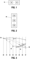
- FIG. 1 shows a block diagram of a tracking system 10 comprising an estimating module 12 and a determining module 14 according to embodiments of the present disclosure.
- the tracking system 10 is a system for tracking at least one pixel from a reference frame to a current frame in a video comprising the reference frame, the current frame and at least one intermediate frame between the reference frame and the current frame, the at least one pixel having a known position in the reference frame.
- the tracking system 10 may comprise an electronic circuit, a processor (shared, dedicated, or group), a combinational logic circuit, a memory that executes one or more software programs, and/or other suitable components that provide the described functionality.
- the tracking system 10 may be a computer device.
- the tracking system 10 may be connected to a memory, which may store data, e.g. at least one computer program which when executed, carries out the tracking method according to the present disclosure.
- the tracking system or the memory may store software which comprises the neural networks described hereinafter.
- the tracking system 10 may have an input for receiving a sequence of frames, e.g. a video.
- the tracking system 10 may be connected to an optical sensor, in particular a digital camera.
- the digital camera is configured such that it can record a scene, and in particular output digital data to the tracking system 10.
- the video may be acquired in real time by an image acquisition module, such as a video acquisition module, e.g. a camera or the like (video cameras, photo cameras, etc.).
- a video acquisition module e.g. a camera or the like (video cameras, photo cameras, etc.).
- the video may be acquired beforehand, and obtained by the tracking system 10 later, e.g. in case of post-processing of the filmed process.
- the estimating module 12 is a module for estimating a plurality of position candidates for the at least one pixel in the current frame, wherein each of the position candidates is obtained by chaining a position of the at least one pixel in a respective anchor frame with an optical flow from the respective anchor frame to the current frame.
- the anchor frame is chosen among the reference frame and the at least one intermediate frame.
- the estimating module 12 may be implemented as software running on the tracking system 10 or as a hardware element of the tracking system 10.
- the estimating module 12 estimates a plurality of position candidates for at least one pixel in a current frame of the video.
- the determining module 14 is a module for determining the position of the at least one pixel in the current frame by selecting one of the position candidates or combining two or more of the position candidates.
- the determining module 14 may be implemented as software running on the tracking system 10 or as a hardware element of the tracking system 10.
- the tracking system 10 may comprise a program which includes both the estimating module 12 and the determining module 14.
- the estimating module 12 may be realized as an independent program (in particular beside a program forming the determining module 14).
- the tasks carried out by the tracking system 10 are detailed hereinafter with respect to a corresponding tracking method, an embodiment of which is illustrated in Fig. 2 .
- FIG. 2 is a flowchart of a tracking method 20 according to an embodiment.
- the tracking method 20 is a method for tracking at least one pixel from a reference frame to a current frame in a video, assuming that the at least one pixel has a known position in the reference frame.
- the tracking method 20 may be used for long-term tracking of every pixel of a reference frame throughout a video.
- the tracking method 20 comprises a step 22 of estimating a plurality of position candidates for the at least one pixel in the current frame, wherein each of the position candidates is obtained by chaining a position of the at least one pixel in a respective anchor frame with an optical flow from the respective anchor frame to the current frame, wherein the anchor frame is chosen among the reference frame and the at least one intermediate frame.
- the estimating step 22 relies on a plurality of optical flow fields computed over different time spans (e.g. from different anchor frames). Therefore, in the present disclosure, the tracking method 20 may also be referred to as Multi-Flow Tracker or MFT in short.
- Figure 3 shows an example in which a video comprises 8 frames numbered from frame #0 to frame #7. Although generally two-dimensional, the frames are represented in one dimension (i.e. as a line) in Fig. 3 for simplicity.
- frame #0 is chosen as the reference frame, and it is desired to track at least one pixel of reference frame #0 to frame #7, which is thus the current frame.
- Intermediate frames #1 to #6 separate the reference frame #0 from the current frame #7.
- the number of frames of the video could vary, the reference frame needs not be the first frame, the current frame needs not be the last frame, and the reference frame needs not precede the current frame.
- the estimating step 22 considers a plurality of anchor frames different from the current frame #7, e.g. the reference frame #0 and intermediate frames #3, #5 and #6.
- the frame difference between the current frame #7 and each anchor frame is noted as ⁇ .
- ⁇ 4.
- the current frame #7 and the intermediate frames #6, #5, #3 serving as anchor frames may be increasingly spaced from one another in a direction from the current frame #7 to the reference frame #0.
- the current frame #7 and the intermediate frames #6, #5, #3 may be logarithmically spaced from one another, i.e. the frame difference ⁇ increases exponentially (here as 2 n ).
- the reference frame #0 may be included in the anchor frames or not irrespective of the increasing or logarithmical spacing of the intermediate frames.
- a position of the tracked pixel is assumed to be known in each anchor frame.
- the position 30 of the pixel is known of course; however, for the other anchor frames #3, #5, #6, the position 32 of the pixel may be estimated or otherwise obtained.
- the position of the pixel in frame #1 adjacent the reference frame #0 may be obtained by chaining the known position of the pixel in reference frame #0 and an optical flow from reference frame #0 to the adjacent frame #1.
- Position of the pixel in subsequent frames #2, #3, etc. may be obtained likewise from the position in the adjacent frame #1, by considering pairs of consecutive frames.
- the position 32 of the pixel in an intermediate frame may be obtained in a recursive manner by applying the tracking method 20 itself to a fewer number of frames (because the current frame #7 is excluded).
- An iterative implementation will be detailed hereinafter.
- Fig. 3 the known position 30 or estimated position 32 of the pixel in every frame, or at least in every one of the anchor frames, is represented as a dot.
- a dashed arrow illustrates the overall displacement from reference frame #0 to the corresponding anchor intermediate frame #3, #5, #6, irrespective of whether this overall displacement was obtained as a direct single displacement or through a plurality of shorter displacements.
- the estimating step 22 chains said position with an optical flow 34 from the respective anchor frame to the current frame #7.
- the optical flow 34 is represented in Fig. 3 as a solid arrow. An example of chaining will be detailed hereinafter.
- a plurality of position candidates 36 for the pixel in the reference frame can be estimated, here four position candidates 36. This shows how one position candidate per anchor frame can be obtained.
- the tracking method 20 further comprises a step 24 of determining the position of the at least one pixel in the current frame by selecting one of the position candidates or combining two or more of the position candidates. Determining step 24 corresponds to a processing of the plurality of position candidates to determine the predicted position of the pixel in the current frame.
- the tracking method 20 further comprises a step 23 of evaluating respective scores of the position candidates. Then, in step 24, the determining may be based on the respective scores.
- the tracking method 20 may apply to a plurality of pixels, e.g. a dense selection of pixels of the video (as opposed to a sparse selection of pixels).
- the estimating step 22 and determining step 24 (and, if applicable, the evaluating step 23) may be carried out independently for each of the at least one pixel.
- the position candidates are formed by combining the MFT result (or more generally an otherwise obtained position) from a previous frame t - ⁇ , with the flow from t - ⁇ to the current frame t.
- MFT constructs a set of position candidates, each with a different ⁇ , then the best candidate is chosen independently for each pixel of the reference frame.
- MFT computes scores such as a non-visibility score and/or an uncertainty score, and propagates a non-visibility map and an uncertainty map in addition to the optical flow fields.
- At least one of the non-visibility score and the uncertainty score may be computed by a machine learning model, optionally by a CNN.
- a machine learning model optionally by a CNN.
- current optical flow methods typically compute the flow from a cost-volume inner representation and image features. Given a pair of input images, I a and I b , the cost-volume encodes similarity between each position in I a and (possibly a subset of) positions in I b .
- the cost-volume may be re-used as an input to two CNNs for non-visibility and uncertainty estimation.
- the CNN may use two convolutional layers with kernel size 3.
- the first layer has 128 output channels and ReLU activation. Both networks take the same input as the flow estimation head and each network outputs a H ⁇ W map.
- Non-visibility prediction may be formulated as a binary classification.
- the machine learning model should output 1 for any point in I a that is not visible (e.g. occluded or out of view) in I b and 0 otherwise.
- the non-visibility CNN with two output channels may be followed by soft-max. During inference, the second output channel may be used as the predicted non-visibility score.
- the non-visibility model may be trained on datasets with non-visibility ground-truth labels (e.g. Sintel [REF. 1]) using standard cross-entropy loss.
- the proposed method sums the non-visibility loss and L u weighted by 1 5 .
- the non-visibility and uncertainty networks may be trained separately while keeping the pre-trained optical flow fixed.
- the scores may be defined differently, so long as the non-visibility score qualifies whether the pixel is visible or not in the frame and the uncertainty score quantifies a level of confidence in the position prediction.
- the non-visibility score qualifies whether the pixel is visible or not in the frame and the uncertainty score quantifies a level of confidence in the position prediction.
- some optical flow networks can track a pixel even when the pixel is occluded in a subsequent frame, e.g. by considering the motion of the surrounding pixels. While this may be beneficial when tracking only between consecutive frames, it introduces drift when the position in the subsequent frame is used for tracking in further frames.
- the F 0 ⁇ t may be a H ⁇ W ⁇ 2 map of position differences between frame 0 and frame t, e.g. in the conventional optical flow format.
- the O 0 ⁇ t and U 0 ⁇ t may be H ⁇ W maps with the current non-visibility and uncertainty scores respectively.
- all three maps contain zeros only (no motion, all pixels visible, no uncertainty)
- the triplet is directly the output of the optical flow network and the non-visibility and uncertainty CNNs.
- the results are not the direct outputs of the network, but instead they are formed by chaining two ( F, O, U ) triplets together, e.g. as described below.
- the MFT is parameterized by D, a set of time (or number of frames) deltas.
- D a set of time (or number of frames) deltas.
- D ⁇ ,1,2,4,8,16,32 ⁇ by default.
- other (possibly increasingly spaced) deltas may be selected, in an exponential manner or not.
- the set D defines which frames will serve as the anchor frames.
- the method estimates a result candidate (including a position candidate and the associated scores) that is formed by chaining two parts: a previously computed result FOU 0 ⁇ ( t - ⁇ ) and a network output FOU ( t - ⁇ ) ⁇ t as shown in Fig. 3 .
- (t - ⁇ ) stands for max (0, t - ⁇ ) to avoid invalid negative frame numbers.
- the optical flow F ( t - ⁇ ) ⁇ t sampled at the appropriate position, is added to the motion between frames 0 and ( t - ⁇ ).
- the position candidate is obtained by chaining a position of the at least one pixel in a respective anchor frame with an optical flow from the respective anchor frame to the current frame:
- F 0 ⁇ t ⁇ p F ⁇ 0 ⁇ t ⁇ ⁇ p + F t ⁇ ⁇ ⁇ t P ⁇ t ⁇ ⁇ p s
- a [ b ] s means the value in a map A sampled at possibly non-integer spatial coordinates b with bilinear interpolation.
- Bilinear interpolation (e.g. in height and width) may be needed to sample the flow field, since the calculated positions may not align with the pixel grid.
- equation (4) corresponds to a "or" operation - the chain is declared non-visible whenever at least one of its parts is not visible.
- the uncertainty score may be calculated based on a first uncertainty score of the position of the at least one pixel in the respective anchor frame and a second uncertainty score of the optical flow from the respective anchor frame to the current frame.
- the determining step 24 selects the best ⁇ , noted as ⁇ ⁇ , according to the scores, namely the candidate uncertainty and non-visibility maps.
- the determining comprises identifying a position candidate as a least likely position candidate if the non-visibility score of the position candidate indicates that the at least one pixel is not visible in the current frame or in the corresponding anchor frame.
- MFT picks the ⁇ that results in the lowest uncertainty score among the visible candidates.
- a threshold ⁇ o 0.02, but may be adapted empirically.
- ⁇ * p argmin ⁇ ⁇ D U 0 ⁇ t ⁇ p + ⁇ ⁇ O 0 ⁇ t ⁇ p > ⁇ o
- [[ x ]] is the Iverson bracket (equal to 1 when condition x holds, 0 otherwise).
- the infinity sign means that non-visible candidates are infinitely worse than visible candidates, which amounts to identifying them as least likely candidates. Notice that the ⁇ ⁇ , and thus the best position candidate, is selected independently for each pixel. In determining ⁇ ⁇ , MFT selects the anchor frame through which the best position candidate is determined.
- the template i.e. the reference frame
- the determining step 24 may combine two or more of the position candidates. For instance, the determining step 24 may discard the position candidates having a non-visibility score reaching the threshold, and may calculate an average of the remaining position candidates. The average may be weighted by the respective uncertainty scores.
- MFT memorizes and outputs the resulting triplet FOU 0 ⁇ t and may discard memorized results that will no longer be needed (more than max ( D ⁇ ⁇ ) frames old).
- query positions p i, 0 on the reference frame 0 their current positions and non-visibility scores may be computed by bilinear interpolation of the FOU result.
- the optical flow computation uses the official RAFT [REF. 3] implementation with author-provided weights.
- Both the non-visibility and the uncertainty CNNs may operate on the same inputs as the RAFT flow regression CNN, i.e. samples from the RAFT cost-volume, context features, and Conv-GRU outputs.
- the optical flows and the scores can be pre-computed offline.
- MFT needs to compute just one optical flow per frame during inference, so the tracking speed stays reasonably fast, as the slowest part of the method, namely the optical flow computation, has been prepared beforehand.
- Set (4) which corresponds to the full MFT method exemplified above, achieves the overall best results, with a plurality of appropriate metrics.
- the last version (5) achieves second best overall performance.
- the third version (3) already achieves significant improvement over (1) and (2); this version may be seen as a lightweight variant that only computes two optical flow fields on each frame and provides good performance-speed tradeoff.
Landscapes
- Engineering & Computer Science (AREA)
- Multimedia (AREA)
- Computer Vision & Pattern Recognition (AREA)
- Physics & Mathematics (AREA)
- General Physics & Mathematics (AREA)
- Theoretical Computer Science (AREA)
- Image Analysis (AREA)
Priority Applications (1)
| Application Number | Priority Date | Filing Date | Title |
|---|---|---|---|
| EP23173791.7A EP4465239A1 (de) | 2023-05-16 | 2023-05-16 | Verfahren und system zur verfolgung eines pixels in einem video |
Applications Claiming Priority (1)
| Application Number | Priority Date | Filing Date | Title |
|---|---|---|---|
| EP23173791.7A EP4465239A1 (de) | 2023-05-16 | 2023-05-16 | Verfahren und system zur verfolgung eines pixels in einem video |
Publications (1)
| Publication Number | Publication Date |
|---|---|
| EP4465239A1 true EP4465239A1 (de) | 2024-11-20 |
Family
ID=86387308
Family Applications (1)
| Application Number | Title | Priority Date | Filing Date |
|---|---|---|---|
| EP23173791.7A Pending EP4465239A1 (de) | 2023-05-16 | 2023-05-16 | Verfahren und system zur verfolgung eines pixels in einem video |
Country Status (1)
| Country | Link |
|---|---|
| EP (1) | EP4465239A1 (de) |
Citations (1)
| Publication number | Priority date | Publication date | Assignee | Title |
|---|---|---|---|---|
| US20150379728A1 (en) * | 2013-02-05 | 2015-12-31 | Thomson Licensing | Method for generating a motion field for a video sequence |
-
2023
- 2023-05-16 EP EP23173791.7A patent/EP4465239A1/de active Pending
Patent Citations (1)
| Publication number | Priority date | Publication date | Assignee | Title |
|---|---|---|---|---|
| US20150379728A1 (en) * | 2013-02-05 | 2015-12-31 | Thomson Licensing | Method for generating a motion field for a video sequence |
Non-Patent Citations (6)
| Title |
|---|
| CONZE PIERRE-HENRI ET AL: "Dense long-term motion estimation via statistical multi-step flow", 2014 INTERNATIONAL CONFERENCE ON COMPUTER VISION THEORY AND APPLICATIONS (VISAPP), SCITEPRESS, vol. 3, 5 January 2014 (2014-01-05), pages 545 - 554, XP032792223 * |
| CONZE PIERRE-HENRI ET AL: "Dense motion estimation between distant frames: Combinatorial multi-step integration and statistical selection", 2013 IEEE INTERNATIONAL CONFERENCE ON IMAGE PROCESSING, IEEE, 15 September 2013 (2013-09-15), pages 3860 - 3864, XP032966355, DOI: 10.1109/ICIP.2013.6738795 * |
| CONZE PIERRE-HENRI ET AL: "Multi-reference combinatorial strategy towards longer long-term dense motion estimation", COMPUTER VISION AND IMAGE UNDERSTANDING, ACADEMIC PRESS, US, vol. 150, 20 May 2016 (2016-05-20), pages 66 - 80, XP029628348, ISSN: 1077-3142, DOI: 10.1016/J.CVIU.2016.04.013 * |
| DANIEL J BUTLERJONAS WULFFGARRETT B STANLEYMICHAEL J BLACK: "In Computer Vision-ECCV 2012: 12th European Conference on Computer Vision, Florence, Italy", vol. 12, SPRINGER, article "A naturalistic open source movie for optical flow evaluation", pages: 611 - 625 |
| PETER J HUBER: "Robust estimation of a location parameter", BREAKTHROUGHS IN STATISTICS: METHODOLOGY AND DISTRIBUTION, 1992, pages 492 - 518 |
| ZACHARY TEEDJIA DENG: "European Conference on Computer Vision", SPRINGER, article "RAFT: Recurrent all-pairs field transforms for optical flow", pages: 402 - 419 |
Similar Documents
| Publication | Publication Date | Title |
|---|---|---|
| Gehrig et al. | E-raft: Dense optical flow from event cameras | |
| US11720798B2 (en) | Foreground-background-aware atrous multiscale network for disparity estimation | |
| EP3698323B1 (de) | Bewegungstiefe für erweiterte realität für tragbare benutzergeräte | |
| US11176381B2 (en) | Video object segmentation by reference-guided mask propagation | |
| EP2352128B1 (de) | Verfahren zur erkennung bewegter objekte und vorrichtung zur erkennung bewegter objekte | |
| Babaee et al. | Occlusion handling in tracking multiple people using RNN | |
| KR102201297B1 (ko) | 다중 플로우 기반 프레임 보간 장치 및 방법 | |
| US20220270354A1 (en) | Monocular image-based model training method and apparatus, and data processing device | |
| CN117495919B (zh) | 一种基于遮挡物体检测及运动连续性的光流估计方法 | |
| US9811918B2 (en) | Method and apparatus for estimating image optical flow | |
| US12340595B2 (en) | Lane detection system and method for a vehicle | |
| CN117935260A (zh) | 标注方法、装置、电子设备和存储介质 | |
| CN105590327A (zh) | 运动估计方法及装置 | |
| CN111192306A (zh) | 用于视差估计的系统及用于系统的视差估计的方法 | |
| Makino et al. | Moving-object detection method for moving cameras by merging background subtraction and optical flow methods | |
| CN110580712A (zh) | 一种使用运动信息与时序信息的改进CFNet视频目标追踪方法 | |
| Kim et al. | Loop-net: Joint unsupervised disparity and optical flow estimation of stereo videos with spatiotemporal loop consistency | |
| Chae et al. | Siamevent: Event-based object tracking via edge-aware similarity learning with siamese networks | |
| EP3043315B1 (de) | Verfahren und vorrichtung zur erzeugung von superpixeln für mehrfachansichtsbilder | |
| EP4465239A1 (de) | Verfahren und system zur verfolgung eines pixels in einem video | |
| CN106416244A (zh) | 运动场估计 | |
| CN116523972A (zh) | 基于稀疏光流运动补偿的两阶段多目标追踪方法及产品 | |
| CN112131991B (zh) | 一种基于事件相机的数据关联方法 | |
| CN116188535B (zh) | 基于光流估计的视频跟踪方法、装置、设备及存储介质 | |
| CN108257156B (zh) | 一种从视频中自动追踪目标物体的方法 |
Legal Events
| Date | Code | Title | Description |
|---|---|---|---|
| PUAI | Public reference made under article 153(3) epc to a published international application that has entered the european phase |
Free format text: ORIGINAL CODE: 0009012 |
|
| STAA | Information on the status of an ep patent application or granted ep patent |
Free format text: STATUS: REQUEST FOR EXAMINATION WAS MADE |
|
| 17P | Request for examination filed |
Effective date: 20230516 |
|
| AK | Designated contracting states |
Kind code of ref document: A1 Designated state(s): AL AT BE BG CH CY CZ DE DK EE ES FI FR GB GR HR HU IE IS IT LI LT LU LV MC ME MK MT NL NO PL PT RO RS SE SI SK SM TR |
|
| STAA | Information on the status of an ep patent application or granted ep patent |
Free format text: STATUS: EXAMINATION IS IN PROGRESS |
|
| 17Q | First examination report despatched |
Effective date: 20260320 |