EP4465102A1 - Optical fiber cable - Google Patents
Optical fiber cable Download PDFInfo
- Publication number
- EP4465102A1 EP4465102A1 EP23740272.2A EP23740272A EP4465102A1 EP 4465102 A1 EP4465102 A1 EP 4465102A1 EP 23740272 A EP23740272 A EP 23740272A EP 4465102 A1 EP4465102 A1 EP 4465102A1
- Authority
- EP
- European Patent Office
- Prior art keywords
- optical fiber
- cable
- fiber cable
- core
- main body
- Prior art date
- Legal status (The legal status is an assumption and is not a legal conclusion. Google has not performed a legal analysis and makes no representation as to the accuracy of the status listed.)
- Pending
Links
- 239000013307 optical fiber Substances 0.000 title claims abstract description 151
- 239000000835 fiber Substances 0.000 description 20
- 238000009434 installation Methods 0.000 description 18
- 230000001681 protective effect Effects 0.000 description 9
- 229920002430 Fibre-reinforced plastic Polymers 0.000 description 7
- 239000011151 fibre-reinforced plastic Substances 0.000 description 7
- 238000007526 fusion splicing Methods 0.000 description 5
- 230000005540 biological transmission Effects 0.000 description 3
- 230000008602 contraction Effects 0.000 description 2
- 239000011521 glass Substances 0.000 description 2
- 239000000463 material Substances 0.000 description 2
- 229920000728 polyester Polymers 0.000 description 2
- 239000011347 resin Substances 0.000 description 2
- 229920005989 resin Polymers 0.000 description 2
- OKTJSMMVPCPJKN-UHFFFAOYSA-N Carbon Chemical compound [C] OKTJSMMVPCPJKN-UHFFFAOYSA-N 0.000 description 1
- 229920000106 Liquid crystal polymer Polymers 0.000 description 1
- 239000004977 Liquid-crystal polymers (LCPs) Substances 0.000 description 1
- 239000004760 aramid Substances 0.000 description 1
- 229920003235 aromatic polyamide Polymers 0.000 description 1
- 229910052799 carbon Inorganic materials 0.000 description 1
- 238000004891 communication Methods 0.000 description 1
- 230000000694 effects Effects 0.000 description 1
- 238000001125 extrusion Methods 0.000 description 1
- 239000004744 fabric Substances 0.000 description 1
- 239000012765 fibrous filler Substances 0.000 description 1
- 239000002657 fibrous material Substances 0.000 description 1
- 230000001939 inductive effect Effects 0.000 description 1
- 238000003780 insertion Methods 0.000 description 1
- 230000037431 insertion Effects 0.000 description 1
- 239000002184 metal Substances 0.000 description 1
- 238000010295 mobile communication Methods 0.000 description 1
- 238000012986 modification Methods 0.000 description 1
- 230000004048 modification Effects 0.000 description 1
- 239000004033 plastic Substances 0.000 description 1
- 229920003023 plastic Polymers 0.000 description 1
- 239000000843 powder Substances 0.000 description 1
- 230000007704 transition Effects 0.000 description 1
Images


Classifications
-
- G—PHYSICS
- G02—OPTICS
- G02B—OPTICAL ELEMENTS, SYSTEMS OR APPARATUS
- G02B6/00—Light guides; Structural details of arrangements comprising light guides and other optical elements, e.g. couplings
- G02B6/24—Coupling light guides
- G02B6/36—Mechanical coupling means
- G02B6/38—Mechanical coupling means having fibre to fibre mating means
- G02B6/3807—Dismountable connectors, i.e. comprising plugs
- G02B6/3873—Connectors using guide surfaces for aligning ferrule ends, e.g. tubes, sleeves, V-grooves, rods, pins, balls
- G02B6/3885—Multicore or multichannel optical connectors, i.e. one single ferrule containing more than one fibre, e.g. ribbon type
-
- G—PHYSICS
- G02—OPTICS
- G02B—OPTICAL ELEMENTS, SYSTEMS OR APPARATUS
- G02B6/00—Light guides; Structural details of arrangements comprising light guides and other optical elements, e.g. couplings
- G02B6/44—Mechanical structures for providing tensile strength and external protection for fibres, e.g. optical transmission cables
- G02B6/4401—Optical cables
- G02B6/4429—Means specially adapted for strengthening or protecting the cables
- G02B6/443—Protective covering
-
- G—PHYSICS
- G02—OPTICS
- G02B—OPTICAL ELEMENTS, SYSTEMS OR APPARATUS
- G02B6/00—Light guides; Structural details of arrangements comprising light guides and other optical elements, e.g. couplings
- G02B6/24—Coupling light guides
- G02B6/36—Mechanical coupling means
- G02B6/38—Mechanical coupling means having fibre to fibre mating means
- G02B6/3807—Dismountable connectors, i.e. comprising plugs
- G02B6/3833—Details of mounting fibres in ferrules; Assembly methods; Manufacture
- G02B6/3847—Details of mounting fibres in ferrules; Assembly methods; Manufacture with means preventing fibre end damage, e.g. recessed fibre surfaces
- G02B6/3849—Details of mounting fibres in ferrules; Assembly methods; Manufacture with means preventing fibre end damage, e.g. recessed fibre surfaces using mechanical protective elements, e.g. caps, hoods, sealing membranes
-
- G—PHYSICS
- G02—OPTICS
- G02B—OPTICAL ELEMENTS, SYSTEMS OR APPARATUS
- G02B6/00—Light guides; Structural details of arrangements comprising light guides and other optical elements, e.g. couplings
- G02B6/44—Mechanical structures for providing tensile strength and external protection for fibres, e.g. optical transmission cables
- G02B6/4401—Optical cables
- G02B6/4429—Means specially adapted for strengthening or protecting the cables
- G02B6/443—Protective covering
- G02B6/4432—Protective covering with fibre reinforcements
- G02B6/4433—Double reinforcement laying in straight line with optical transmission element
-
- G—PHYSICS
- G02—OPTICS
- G02B—OPTICAL ELEMENTS, SYSTEMS OR APPARATUS
- G02B6/00—Light guides; Structural details of arrangements comprising light guides and other optical elements, e.g. couplings
- G02B6/44—Mechanical structures for providing tensile strength and external protection for fibres, e.g. optical transmission cables
- G02B6/4439—Auxiliary devices
- G02B6/4471—Terminating devices ; Cable clamps
-
- G—PHYSICS
- G02—OPTICS
- G02B—OPTICAL ELEMENTS, SYSTEMS OR APPARATUS
- G02B6/00—Light guides; Structural details of arrangements comprising light guides and other optical elements, e.g. couplings
- G02B6/46—Processes or apparatus adapted for installing or repairing optical fibres or optical cables
- G02B6/50—Underground or underwater installation; Installation through tubing, conduits or ducts
- G02B6/52—Underground or underwater installation; Installation through tubing, conduits or ducts using fluid, e.g. air
-
- G—PHYSICS
- G02—OPTICS
- G02B—OPTICAL ELEMENTS, SYSTEMS OR APPARATUS
- G02B6/00—Light guides; Structural details of arrangements comprising light guides and other optical elements, e.g. couplings
- G02B6/02—Optical fibres with cladding with or without a coating
- G02B6/02042—Multicore optical fibres
-
- G—PHYSICS
- G02—OPTICS
- G02B—OPTICAL ELEMENTS, SYSTEMS OR APPARATUS
- G02B6/00—Light guides; Structural details of arrangements comprising light guides and other optical elements, e.g. couplings
- G02B6/44—Mechanical structures for providing tensile strength and external protection for fibres, e.g. optical transmission cables
- G02B6/4401—Optical cables
- G02B6/4403—Optical cables with ribbon structure
-
- G—PHYSICS
- G02—OPTICS
- G02B—OPTICAL ELEMENTS, SYSTEMS OR APPARATUS
- G02B6/00—Light guides; Structural details of arrangements comprising light guides and other optical elements, e.g. couplings
- G02B6/44—Mechanical structures for providing tensile strength and external protection for fibres, e.g. optical transmission cables
- G02B6/4401—Optical cables
- G02B6/4429—Means specially adapted for strengthening or protecting the cables
- G02B6/443—Protective covering
- G02B6/4431—Protective covering with provision in the protective covering, e.g. weak line, for gaining access to one or more fibres, e.g. for branching or tapping
-
- G—PHYSICS
- G02—OPTICS
- G02B—OPTICAL ELEMENTS, SYSTEMS OR APPARATUS
- G02B6/00—Light guides; Structural details of arrangements comprising light guides and other optical elements, e.g. couplings
- G02B6/44—Mechanical structures for providing tensile strength and external protection for fibres, e.g. optical transmission cables
- G02B6/4401—Optical cables
- G02B6/4429—Means specially adapted for strengthening or protecting the cables
- G02B6/44384—Means specially adapted for strengthening or protecting the cables the means comprising water blocking or hydrophobic materials
Definitions
- the present disclosure relates to an optical fiber cable.
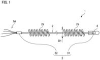
- FIG. 1 illustrates an optical fiber cable 1 according to the present embodiment.
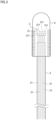
- FIG. 2 is a view illustrating an end portion of the optical fiber cable 1.
- the optical fiber cable 1 of the present embodiment is an optical fiber cable for pneumatic feeding for which an installation work is performed by pneumatic feeding.
- the optical fiber cable 1 includes a cable main body 2 and a connecting member 3.
- the cable main body 2 is provided therein with a plurality of optical fibers 21 each having a plurality of core portions 211.
- the connecting member 3 is provided at a first end portion of the cable main body 2 and, upon connection with another optical fiber cable (not shown), holds the optical fibers 21 each having a plurality of core portions 211 described below and optical fibers 21 of another optical fiber cable to be connectable.
- the optical fiber cable 1 further includes a protective tube 4.
- the protective tube 4 is provided at the first end portion of the cable main body 2.
- the protective tube 4 is made of, for example, metal, and is provided to cover the connecting member 3.
- the protective tube 4 protects the first end portion of the cable main body 2 and the connecting member 3 from damage when installing the optical fiber cable 1 by pneumatic feeding.
- FIG. 3 is a cross-sectional view of the cable main body 2.
- the cable main body 2 includes, for example, a plurality of optical fibers 21 constituting a plurality of optical fiber ribbons 20, a water-absorbing tape 22, a cable sheath 23, at least one tensile strength member 24, at least one tear cord 25 (fibrous filler), and a plurality of projections 26.
- the tensile strength member 24 is arranged along a longitudinal direction of the cable main body 2.
- a diameter of the tensile strength member 24 is, for example, 0.5 mm.
- the tensile strength member 24 is formed of, for example, fiber-reinforced plastic (FRP) such as aramid FRP, glass FRP, and carbon FRP.
- FRP fiber-reinforced plastic
- the tensile strength member 24 may also be formed of liquid crystal polymer.
- the tensile strength member 24 preferably has a non-inductive property. Note that fiber-reinforced plastic (FRP) is generally a flammable material.
- the tear cord 25 is provided for tearing the cable sheath 23.
- the tear cord 25 is provided in the cable sheath 23 along the longitudinal direction of the cable main body 2.
- two tear cords 25 are provided.
- the two tear cords 25 are arranged to face each other, for example, across the center of the cable main body 2.
- the tear cord 25 is made of a fibrous material, for example, a plastic material (for example, polyester) that is resistant to tension.
- the cable main body 2 includes the tensile strength members 24, in addition to the multi-core fibers and the cable sheath 23.
- the optical fiber cable 1 has a certain rigidity, it is difficult for the optical fiber cable to kink even when installed by pneumatic feeding.
- the optical fiber cable 1 includes the connecting member 3 for a multi-core fiber provided at the first end portion of the cable main body 2.
- An aligning work for connecting the multi-core fibers during fusion-splicing becomes unnecessary at the first end portion where the connecting member 3 is provided, and a work for providing a connector or the like at the terminal of the optical fiber cable 1 after installation becomes unnecessary.
- a curl outer diameter D1 which is a helical outer diameter of the curled portion 2a, is preferably 50 mm or greater and 300 mm or less.
- the curl outer diameter is too small, transmission loss of the optical fiber cable 1 may increase due to curl processing.
- the curl outer diameter is too large, an outer diameter of the entire optical fiber cable 1 increases, so the workability of installation by pneumatic feeding may decrease.
- the connecting member 3 provided at the second end portion of the cable main body 2, which is different from the first end portion where the protective tube 4 is provided, is a convertor 32.
- the convertor 32 keeps the optical fiber cable 1, which includes multi-core fibers therein, and an optical fiber cable 1A, which includes single-core fibers therein, to be connectable.
- FIG. 5 is a schematic view for illustrating the convertor 32.
- the convertor 32 holds the multi-core optical fibers 21 by inserting the multi-core optical fibers 21 therein.
- the convertor 32 is configured to connect a single-core optical fiber 21A having a single core portion to each core portion 211 (see FIG. 4 ) of the multi-core fiber.
- the convertor 32 exposes the single-core optical fibers 21A in a direction on an opposite side to a direction in which the convertor 32 receives insertion of the multi-core optical fibers 21.
- the number of core portions is preferably the same.
- 12 single-core optical fibers 21A are preferably connected to the convertor 32.
- the 12 single-core optical fibers 21A connected to the convertor 32 may constitute an optical fiber ribbon composed of 12-core optical fiber 21A.
- the 12-core optical fiber ribbon may be an intermittent connection-type optical fiber ribbon in which connected portions and non-connected portions are alternately provided. In the connection portion, adjacent optical fibers 21A are connected to each other. In the non-connected portion, adjacent optical fibers 21A are spaced apart from each other.
Landscapes
- Physics & Mathematics (AREA)
- General Physics & Mathematics (AREA)
- Optics & Photonics (AREA)
- Mechanical Coupling Of Light Guides (AREA)
- Light Guides In General And Applications Therefor (AREA)
Abstract
Description
- The present disclosure relates to an optical fiber cable.
- This application claims priority to
Japanese Patent Application No. 2022-003066 filed on January 12, 2022 -
Patent Literature 1 discloses an optical fiber cable for pneumatic feeding including a plurality of optical fiber ribbons, a cable sheath, and a tensile strength member embedded in the cable sheath. - Patent Literature 1:
JP2020-204752A - An optical fiber cable according to an aspect of the present disclosure includes:
- a cable main body including a plurality of optical fibers, each of the plurality of optical fibers including: a plurality of core portions; a cable sheath inside which the plurality of optical fibers are housed; and at least one tensile strength member embedded in the cable sheath; and
- a connecting member provided at a first end portion of the cable main body.
-
- [
FIG. 1] FIG. 1 illustrates an optical fiber cable according to the present embodiment. - [
FIG. 2] FIG. 2 is a view illustrating an end portion of the optical fiber cable. - [
FIG. 3] FIG. 3 is a cross-sectional view of a cable main body. - [
FIG. 4] FIG. 4 is a cross-sectional view of an optical fiber. - [
FIG. 5] FIG. 5 is a schematic view for illustrating a convertor. - In order to cope with transition to next-generation mobile communication systems and an increase in communication speed required due to an increase in video information, a need for an optical fiber cable of multi-core fibers with high core density is increasing. In general, terminals of optical fiber cables are connected to each other by fusion-splicing. However, fusion-splicing for multi-core fibers requires rotational alignment of cores, making it difficult to perform fusion-splicing in a lump. For this reason, the time required for the splicing work tends to be long.
- According to the present disclosure, it is possible to provide an optical fiber cable using multi-core fibers, with good workability of connection work after installation.
- First, embodiments of the present disclosure are enumerated and described.
- (1) An optical fiber cable according to an aspect of the present disclosure includes:
- a cable main body including a plurality of optical fibers, each of the plurality of optical fibers including: a plurality of core portions; a cable sheath inside which the plurality of optical fibers are housed; and at least one tensile strength member embedded in the cable sheath; and
- a connecting member provided at a first end portion of the cable main body.
- (2) The optical fiber cable according to the above (1), in which at least a part of the cable main body may be curled.
A curled portion of the cable main body can be expanded and contracted in a direction in which the cable main body extends. Thereby, in a case where the connecting member is provided in advance, even when an installation length and an actual length of the cable main body are different, a length of the cable main body can be adjusted to the installation length by expansion and contraction of the curled portion. - (3) The optical fiber cable according to the above (2), in which a curl outer diameter of the cable main body that is curled may be 50 mm or greater and 300 mm or less.
According to the above configuration, an increase in transmission loss of the optical fiber cable due to curl processing is suppressed, and a decrease in workability of installing the optical fiber cable by pneumatic feeding is suppressed. - (4) The optical fiber cable according to any one of the above (1) to (3), in which the connecting member may be a multi-core connector.
According to the above configuration, the multi-core connector is used as the connecting member, so that it can be connected as is to another optical fiber cable, leading to improvement in workability of connection after installation. - (5) The optical fiber cable according to any one of the above (1) to (4), in which the connecting member may be connected to a second end portion of the cable main body.
According to the above configuration, the connecting member is also provided at the second end portion of the cable main body, so that the optical fiber cable can be connected as is at the first end portion and the second end portion to other optical fiber cables, leading to further improvement in workability of connection after installation. - (6) The optical fiber cable according to the above (5), in which one of the connecting members connected to the first end portion and the second end portion may be a convertor configured to convert and connect the plurality of optical fibers, each of the plurality of optical fibers including the plurality of core portions, to optical fibers, each of the optical fibers including a single-core portion.
According to the above configuration, the convertor capable of converting and connecting a multi-core fiber (an optical fiber having a plurality of core portions) to single-core fibers (optical fibers each having a single core portion) is provided at a tip end of the optical fiber. For this reason, connection with an optical fiber cable having single-core fibers can be facilitated. - (7) The optical fiber cable according to any one of the above (1) to (6), in which the optical fiber cable may be configured to be pneumatically fed within a duct.
The optical fiber cable of the above-described configuration is likely to have improved workability regarding connection after installation, even when it is installed by pneumatic feeding. - A specific example of an optical fiber cable according to an embodiment of the present disclosure will be described below with reference to the drawings. Note that the present invention is not limited to the example, is defined by the claims, and is intended to include all changes made within the meaning and scope equivalent to the claims.
-
FIG. 1 illustrates anoptical fiber cable 1 according to the present embodiment.FIG. 2 is a view illustrating an end portion of theoptical fiber cable 1. Theoptical fiber cable 1 of the present embodiment is an optical fiber cable for pneumatic feeding for which an installation work is performed by pneumatic feeding. As shown inFIG. 1 , theoptical fiber cable 1 includes a cablemain body 2 and a connectingmember 3. In addition, as shown inFIG. 2 , the cablemain body 2 is provided therein with a plurality ofoptical fibers 21 each having a plurality ofcore portions 211. In addition, the connectingmember 3 is provided at a first end portion of the cablemain body 2 and, upon connection with another optical fiber cable (not shown), holds theoptical fibers 21 each having a plurality ofcore portions 211 described below andoptical fibers 21 of another optical fiber cable to be connectable. - The
optical fiber cable 1 further includes aprotective tube 4. Theprotective tube 4 is provided at the first end portion of the cablemain body 2. Theprotective tube 4 is made of, for example, metal, and is provided to cover the connectingmember 3. Theprotective tube 4 protects the first end portion of the cablemain body 2 and the connectingmember 3 from damage when installing theoptical fiber cable 1 by pneumatic feeding. -
FIG. 3 is a cross-sectional view of the cablemain body 2. As shown inFIG. 3 , the cablemain body 2 includes, for example, a plurality ofoptical fibers 21 constituting a plurality ofoptical fiber ribbons 20, a water-absorbingtape 22, acable sheath 23, at least onetensile strength member 24, at least one tear cord 25 (fibrous filler), and a plurality ofprojections 26. - The water-absorbing
tape 22 is wound, for example, longitudinally or spirally, so as to cover an entire periphery of the plurality of optical fiber ribbons 20. The water-absorbingtape 22 is a tape that has undergone water-absorbing processing by attaching water-absorbing powder to a base fabric made of, for example, polyester. Note that, in the present embodiment, theoptical fiber cable 1 includes the water-absorbingtape 22, but theoptical fiber cable 1 may not necessarily include the water-absorbingtape 22. - The
cable sheath 23 covers a periphery of the water-absorbingtape 22. In other words, thecable sheath 23 houses the plurality of optical fiber ribbons 20 (the plurality of optical fibers 21). In thecable sheath 23, a plurality oftensile strength members 24 are embedded. - The
tensile strength member 24 is arranged along a longitudinal direction of the cablemain body 2. A diameter of thetensile strength member 24 is, for example, 0.5 mm. Thetensile strength member 24 is formed of, for example, fiber-reinforced plastic (FRP) such as aramid FRP, glass FRP, and carbon FRP. However, thetensile strength member 24 may also be formed of liquid crystal polymer. Thetensile strength member 24 preferably has a non-inductive property. Note that fiber-reinforced plastic (FRP) is generally a flammable material. From a standpoint of improving flame retardancy of the entireoptical fiber cable 1, thetensile strength member 24 is preferably arranged in thecable sheath 23 at a position close to a center of theoptical fiber cable 1 rather than near a surface of thecable sheath 23. - In the present embodiment, in a cross-sectional view of the cable
main body 2, thetensile strength member 24 has a circular shape. In the present embodiment, eighttensile strength members 24 are provided in thecable sheath 23. Note that in the present embodiment, thetensile strength members 24 are provided in pairs of two per set. The set is referred to as a tensile strength member set 240. In other words, four tensile strength member sets 240 are provided in thecable sheath 23. - In the cable
main body 2 according to the present embodiment, the four tensile strength members sets 240 are spaced apart from each other at equal intervals. Specifically, the tensile strength member sets 240 are provided one by one at facing positions across the center of theoptical fiber cable 1 in the radial cross section of theoptical fiber cable 1. The tensile strength member sets 240 in the radial cross section of theoptical fiber cable 1 are arranged so that two straight lines each connecting the facing tensile strength member sets 240 are orthogonal to each other. - The
tear cord 25 is provided for tearing thecable sheath 23. Thetear cord 25 is provided in thecable sheath 23 along the longitudinal direction of the cablemain body 2. In the present embodiment, twotear cords 25 are provided. The twotear cords 25 are arranged to face each other, for example, across the center of the cablemain body 2. Thetear cord 25 is made of a fibrous material, for example, a plastic material (for example, polyester) that is resistant to tension. - The
projections 26 are provided on an outer surface of thecable sheath 23 and are formed to protrude radially from thecable sheath 23. In the present embodiment, the twoprojections 26 are provided. The twoprojections 26 are provided along the longitudinal direction of the cablemain body 2. Theprojections 26 are formed integrally with thecable sheath 23 by extrusion molding. Note that, in the present embodiment, the cablemain body 2 is provided with theprojections 26, but the cablemain body 2 may not be provided with theprojection 26. - The two
projections 26 are not necessarily required to be provided continuously. For example, the twoprojections 26 may be provided intermittently. - Next, the
optical fibers 21 constituting theoptical fiber ribbon 20 will be described.FIG. 4 is a cross-sectional view of theoptical fiber 21. As shown inFIG. 4 , theoptical fiber 21 includes a plurality ofcore portions 211, aclad portion 212 that covers a periphery of thecore portions 211, and a coveringportion 213 that covers a periphery of the cladportion 212. Theoptical fiber 21 is a so-called multi-core fiber having the plurality ofcore portions 211. In the following description, the optical fiber having the plurality of core portions may be referred to as a multi-core fiber or multi-core optical fiber, and an optical fiber having a single core portion may be referred to as a single-core fiber or single-core optical fiber. - The core portion is made of glass with a higher refractive index than that of the clad
portion 212. An outer diameter of thecore portion 211 is, for example, 5 µm or greater and 10 µm or less. In the present embodiment, fourcore portions 211 are provided. - The clad
portion 212 is provided to cover the fourcore portions 211, and an outer shape thereof is substantially circular. An outer diameter of the cladportion 212 is, for example, 125 µm. - The covering
portion 213 is provided to cover the periphery of the cladportion 212. The coveringportion 213 is formed of, for example, an ultraviolet curable resin (UV resin). - In the
optical fiber cable 1 according to the present embodiment, the cablemain body 2 includes thetensile strength members 24, in addition to the multi-core fibers and thecable sheath 23. As a result, since theoptical fiber cable 1 has a certain rigidity, it is difficult for the optical fiber cable to kink even when installed by pneumatic feeding. - In addition, the
optical fiber cable 1 includes the connectingmember 3 for a multi-core fiber provided at the first end portion of the cablemain body 2. An aligning work for connecting the multi-core fibers during fusion-splicing becomes unnecessary at the first end portion where the connectingmember 3 is provided, and a work for providing a connector or the like at the terminal of theoptical fiber cable 1 after installation becomes unnecessary. As a result, it is possible to provide theoptical fiber cable 1 using multi-core fibers, with good workability of connection after installation. - Returning to
FIG. 1 , at least a part of the cablemain body 2 is provided with a curledportion 2a formed by curl processing. The curledportion 2a has a helical shape. When tensile force is applied to the curledportion 2a in the longitudinal direction, a helical pitch of the curledportion 2a widens, and the cablemain body 2 and the entireoptical fiber cable 1 are expanded. When the tensile force on the expanded curledportion 2a is released, the helical pitch of the curledportion 2a is reduced, the lengths of the cablemain body 2 and the entireoptical fiber cable 1 are shortened, and the curledportion 2a returns to its original shape. - In the
optical fiber cable 1 according to the present embodiment, the curledportion 2a can be expanded and contracted in a direction in which thecable body portion 2 extends. As a result, even when a planned installation length and an actual length of the cablemain body 2 are different, theoptical fiber cable 1 is adjusted so that the length of the cablemain body 2 becomes the planned installation length by the expansion and contraction of the curledportion 2a. - A curl outer diameter D1, which is a helical outer diameter of the curled
portion 2a, is preferably 50 mm or greater and 300 mm or less. When the curl outer diameter is too small, transmission loss of theoptical fiber cable 1 may increase due to curl processing. In addition, when the curl outer diameter is too large, an outer diameter of the entireoptical fiber cable 1 increases, so the workability of installation by pneumatic feeding may decrease. - In the
optical fiber cable 1 according to the present embodiment, the curl outer diameter D1 is 50 mm or greater and 300 mm or less, so the increase in transmission loss of theoptical fiber cable 1 due to the curl processing is suppressed, and the decrease in workability of installing theoptical fiber cable 1 by pneumatic feeding is suppressed. - Next, the connecting
member 3 will be further described. As shown inFIGS. 1 and2 , in theoptical fiber cable 1 according to the present embodiment, the connectingmember 3 covered by theprotective tube 4 is amulti-core connector 31. Themulti-core connector 31 is, for example, a 192-core connector with an MT connector as a base structure. As shown inFIG. 2 , themulti-core connector 31 includes, for example, a plurality offerrules 311. Theferrule 311 is configured to fix and hold theoptical fiber ribbon 20 by inserting a tip end of theoptical fiber ribbon 20 therein. Theferrule 311 is, for example, a 12-core MT ferrule. - Note that the numbers of the
multi-core connectors 31 and theferrules 311 provided in the present embodiment are not limited to the example inFIGS. 1 and2 . - As described above, in the
optical fiber cable 1 according to the present embodiment, the connectingmember 3 is amulti-core connector 31. Since themulti-core connector 31 enables direct connection with another optical fiber cable, the workability of connecting theoptical fiber cable 1 after installation is improved. - As shown in
FIG. 1 , theoptical fiber cable 1 according to the present embodiment includes the connectingmember 3 not only at the first end portion of the cablemain body 2 on the side where theprotective tube 4 is provided, but also at a second end portion of the cablemain body 2. In this way, the connectingmember 3 is also provided at the second end portion of the cablemain body 2, so that the optical fiber cable can be connected as is at the first end portion and the second end portion to other optical fiber cables, leading to further improvement in workability of connection after installation. - Note that in the
optical fiber cable 1 according to the present embodiment, the connectingmember 3 provided at the second end portion of the cablemain body 2, which is different from the first end portion where theprotective tube 4 is provided, is aconvertor 32. Theconvertor 32 keeps theoptical fiber cable 1, which includes multi-core fibers therein, and anoptical fiber cable 1A, which includes single-core fibers therein, to be connectable. -
FIG. 5 is a schematic view for illustrating theconvertor 32. Theconvertor 32 holds the multi-coreoptical fibers 21 by inserting the multi-coreoptical fibers 21 therein. Theconvertor 32 is configured to connect a single-coreoptical fiber 21A having a single core portion to each core portion 211 (seeFIG. 4 ) of the multi-core fiber. Theconvertor 32 exposes the single-coreoptical fibers 21A in a direction on an opposite side to a direction in which theconvertor 32 receives insertion of the multi-coreoptical fibers 21. - In the multi-core
optical fiber 21 and the single-coreoptical fiber 21A connected to theconvertor 32, the number of core portions is preferably the same. For example, when three multi-coreoptical fibers 21 each having fourcore portions 211 are connected to theconvertor 32, 12 single-coreoptical fibers 21A are preferably connected to theconvertor 32. In this case, as illustrated inFIG. 5 , the 12 single-coreoptical fibers 21A connected to theconvertor 32 may constitute an optical fiber ribbon composed of 12-coreoptical fiber 21A. Additionally, the 12-core optical fiber ribbon may be an intermittent connection-type optical fiber ribbon in which connected portions and non-connected portions are alternately provided. In the connection portion, adjacentoptical fibers 21A are connected to each other. In the non-connected portion, adjacentoptical fibers 21A are spaced apart from each other. - In this way, in the
optical fiber cable 1 according to the present embodiment, theconvertor 32 for converting and connecting the multi-coreoptical fibers 21 each including a plurality ofcore portions 211 to the single-coreoptical fibers 21A each including a single-core portion is provided as the connectingmember 3. Thereby, connection with an optical fiber cable having single-core fibers can be easily achieved. - The
optical fiber cable 1 according to the present embodiment may be configured so that it can be installed by being pneumatically fed in a duct. For example, since theoptical fiber cable 1 according to the present embodiment includes theprotective tube 4, the installation by pneumatic feeding is performed while protecting theoptical fibers 21, themulti-core connector 31, and the like. In theoptical fiber cable 1 that can be installed by such pneumatic feeding, workability regarding connection after installation is likely to be improved. - Although the present disclosure has been described in detail with reference to the specific embodiment, it is obvious to one skilled in the art that a variety of changes and modifications can be made without departing from the spirit and scope of the present disclosure. In addition, the numbers, positions, shapes, and the like of the constitutional members described above are not limited to those in the above embodiment, and can be changed to suitable numbers, positions, shapes, and the like when implementing the present disclosure.
-
- 1: optical fiber cable
- 2: cable main body
- 2a: curled portion
- 3: connecting member
- 4: protective tube
- 20: optical fiber ribbon
- 21, 21A: optical fiber
- 22: water-absorbing tape
- 23: cable sheath
- 24: tensile strength member
- 25: tear cord
- 26: projection
- 31: multi-core connector
- 32: convertor
- 211: core portion
- 212: clad portion
- 213: covering portion
- 240: tensile strength member set
- 311: ferrule
- D1: curl outer diameter
Claims (7)
- An optical fiber cable comprising:a cable main body comprising a plurality of optical fibers, each of the plurality of optical fibers comprising: a plurality of core portions; a cable sheath inside which the plurality of optical fibers are housed; and at least one tensile strength member embedded in the cable sheath; anda connecting member provided at a first end portion of the cable main body.
- The optical fiber cable according to claim 1, wherein at least a part of the cable main body is curled.
- The optical fiber cable according to claim 2, wherein a curl outer diameter of the cable main body that is curled is 50 mm or greater and 300 mm or less.
- The optical fiber cable according to any one of claims 1 to 3, wherein the connecting member is a multi-core connector.
- The optical fiber cable according to any one of claims 1 to 4, wherein the connecting member is connected to a second end portion of the cable main body.
- The optical fiber cable according to claim 5, wherein one of the connecting members connected to the first end portion and the second end portion is a convertor configured to convert and connect the plurality of optical fibers, each of the plurality of optical fibers comprising the plurality of core portions, to optical fibers, each of the optical fibers comprising a single-core portion.
- The optical fiber cable according to any one of claims 1 to 6, wherein the optical fiber cable is configured to be pneumatically fed within a duct.
Applications Claiming Priority (2)
| Application Number | Priority Date | Filing Date | Title |
|---|---|---|---|
| JP2022003066 | 2022-01-12 | ||
| PCT/JP2023/000456 WO2023136263A1 (en) | 2022-01-12 | 2023-01-11 | Optical fiber cable |
Publications (2)
| Publication Number | Publication Date |
|---|---|
| EP4465102A1 true EP4465102A1 (en) | 2024-11-20 |
| EP4465102A4 EP4465102A4 (en) | 2025-04-16 |
Family
ID=87279153
Family Applications (1)
| Application Number | Title | Priority Date | Filing Date |
|---|---|---|---|
| EP23740272.2A Pending EP4465102A4 (en) | 2022-01-12 | 2023-01-11 | FIBER OPTIC CABLE |
Country Status (4)
| Country | Link |
|---|---|
| US (1) | US20250102753A1 (en) |
| EP (1) | EP4465102A4 (en) |
| JP (1) | JPWO2023136263A1 (en) |
| WO (1) | WO2023136263A1 (en) |
Family Cites Families (10)
| Publication number | Priority date | Publication date | Assignee | Title |
|---|---|---|---|---|
| JP2005292205A (en) * | 2004-03-31 | 2005-10-20 | Sumitomo Electric Ind Ltd | Optical fiber cable and optical fiber cable laying method |
| JP5497544B2 (en) * | 2010-06-09 | 2014-05-21 | 住友電気工業株式会社 | Collective optical cable with connector |
| JPWO2014109395A1 (en) * | 2013-01-10 | 2017-01-19 | 住友電気工業株式会社 | Optical component and optical communication system |
| WO2014121034A1 (en) * | 2013-02-01 | 2014-08-07 | Commscope, Inc. Of North Carolina | Transitioning multi-core fiber to plural single core fibers |
| JP2015052704A (en) * | 2013-09-06 | 2015-03-19 | 住友電気工業株式会社 | Optical fiber tape core, optical cable, optical fiber cord, and tape core connection method |
| US9664864B2 (en) * | 2015-10-09 | 2017-05-30 | Commscope Technologies Llc | Method for terminating high fiber count cables |
| SI3386951T1 (en) | 2015-12-09 | 2020-07-31 | F. Hoffmann-La Roche Ag | Phenyl derivatives as cannabinoid receptor 2 agonists |
| WO2020256019A1 (en) * | 2019-06-19 | 2020-12-24 | 住友電気工業株式会社 | Optical fiber cable |
| JP7156181B2 (en) | 2019-06-19 | 2022-10-19 | 住友電気工業株式会社 | fiber optic cable |
| EP4279965A4 (en) * | 2021-01-12 | 2024-06-05 | Sumitomo Electric Industries, Ltd. | FIBER OPTICAL CABLE AND CONNECTOR EQUIPPED CABLE |
-
2023
- 2023-01-11 EP EP23740272.2A patent/EP4465102A4/en active Pending
- 2023-01-11 JP JP2023574047A patent/JPWO2023136263A1/ja active Pending
- 2023-01-11 WO PCT/JP2023/000456 patent/WO2023136263A1/en not_active Ceased
- 2023-01-11 US US18/727,877 patent/US20250102753A1/en active Pending
Also Published As
| Publication number | Publication date |
|---|---|
| WO2023136263A1 (en) | 2023-07-20 |
| US20250102753A1 (en) | 2025-03-27 |
| EP4465102A4 (en) | 2025-04-16 |
| JPWO2023136263A1 (en) | 2023-07-20 |
Similar Documents
| Publication | Publication Date | Title |
|---|---|---|
| EP1831746B1 (en) | Distribution cable having overmolded mid-span access location with preferential bending | |
| JP4733115B2 (en) | Wiring cable assembly with composite molded intermediate branch point | |
| JP4017990B2 (en) | Optical fiber branching device | |
| US20090087148A1 (en) | Optical fiber cables | |
| US7660501B2 (en) | Distribution cable assembly having overmolded mid-span access location | |
| US7703990B1 (en) | Furcation bodies and fiber optic assemblies using the same | |
| US20100220964A1 (en) | Fiber Optic Drop Cable Furcation Assemblies and Methods | |
| JP7800448B2 (en) | Optical fiber cables and cables with connectors | |
| US20230244050A1 (en) | Optical fiber cable and cable with connector | |
| EP4220260A1 (en) | Optical fiber cable and cable with connector | |
| US7778511B1 (en) | Optical fiber cables | |
| EP4465102A1 (en) | Optical fiber cable | |
| CN213399003U (en) | Double-core flat indoor composite optical cable | |
| EP4227720B1 (en) | Optical cable | |
| JP3991204B2 (en) | Multi-fiber optical connector with optical fiber cord | |
| WO2021199736A1 (en) | Housing structure, optical cable with traction end, and production method for housing structure | |
| US20240319466A1 (en) | Optical fiber cable | |
| JP7845195B2 (en) | Cable with connector | |
| WO2022249756A1 (en) | Optical fiber cable | |
| US20090087152A1 (en) | Optical Cable, Arrangement for Connecting a Multiplicity of Optical Waveguides, and Method for Manufacturing an Optical Cable | |
| US20250102754A1 (en) | Optical fiber cable | |
| CN215181104U (en) | Small-size multifunctional optical cable | |
| CN211554409U (en) | Optical cable assembly with subunit design | |
| JP3006595B1 (en) | Metal tube type optical fiber cable terminal with optical connector | |
| CA2639818C (en) | Optical fiber cables |
Legal Events
| Date | Code | Title | Description |
|---|---|---|---|
| STAA | Information on the status of an ep patent application or granted ep patent |
Free format text: STATUS: THE INTERNATIONAL PUBLICATION HAS BEEN MADE |
|
| PUAI | Public reference made under article 153(3) epc to a published international application that has entered the european phase |
Free format text: ORIGINAL CODE: 0009012 |
|
| STAA | Information on the status of an ep patent application or granted ep patent |
Free format text: STATUS: REQUEST FOR EXAMINATION WAS MADE |
|
| 17P | Request for examination filed |
Effective date: 20240711 |
|
| AK | Designated contracting states |
Kind code of ref document: A1 Designated state(s): AL AT BE BG CH CY CZ DE DK EE ES FI FR GB GR HR HU IE IS IT LI LT LU LV MC ME MK MT NL NO PL PT RO RS SE SI SK SM TR |
|
| A4 | Supplementary search report drawn up and despatched |
Effective date: 20250319 |
|
| DAV | Request for validation of the european patent (deleted) | ||
| DAX | Request for extension of the european patent (deleted) | ||
| RIC1 | Information provided on ipc code assigned before grant |
Ipc: G02B 6/52 20060101ALI20250313BHEP Ipc: G02B 6/36 20060101ALI20250313BHEP Ipc: G02B 6/02 20060101ALI20250313BHEP Ipc: G02B 6/44 20060101AFI20250313BHEP |