EP4465053A1 - Measurement apparatus and measurement method - Google Patents
Measurement apparatus and measurement method Download PDFInfo
- Publication number
- EP4465053A1 EP4465053A1 EP24174379.8A EP24174379A EP4465053A1 EP 4465053 A1 EP4465053 A1 EP 4465053A1 EP 24174379 A EP24174379 A EP 24174379A EP 4465053 A1 EP4465053 A1 EP 4465053A1
- Authority
- EP
- European Patent Office
- Prior art keywords
- measured
- voltage
- current
- power
- injection
- Prior art date
- Legal status (The legal status is an assumption and is not a legal conclusion. Google has not performed a legal analysis and makes no representation as to the accuracy of the status listed.)
- Granted
Links
Images



Classifications
-
- G—PHYSICS
- G01—MEASURING; TESTING
- G01R—MEASURING ELECTRIC VARIABLES; MEASURING MAGNETIC VARIABLES
- G01R15/00—Details of measuring arrangements of the types provided for in groups G01R17/00 - G01R29/00, G01R33/00 - G01R33/26 or G01R35/00
- G01R15/14—Adaptations providing voltage or current isolation, e.g. for high-voltage or high-current networks
- G01R15/16—Adaptations providing voltage or current isolation, e.g. for high-voltage or high-current networks using capacitive devices
-
- G—PHYSICS
- G01—MEASURING; TESTING
- G01R—MEASURING ELECTRIC VARIABLES; MEASURING MAGNETIC VARIABLES
- G01R21/00—Arrangements for measuring electric power or power factor
- G01R21/06—Arrangements for measuring electric power or power factor by measuring current and voltage
-
- G—PHYSICS
- G01—MEASURING; TESTING
- G01R—MEASURING ELECTRIC VARIABLES; MEASURING MAGNETIC VARIABLES
- G01R19/00—Arrangements for measuring currents or voltages or for indicating presence or sign thereof
- G01R19/0084—Measuring voltage only
-
- G—PHYSICS
- G01—MEASURING; TESTING
- G01R—MEASURING ELECTRIC VARIABLES; MEASURING MAGNETIC VARIABLES
- G01R31/00—Arrangements for testing electric properties; Arrangements for locating electric faults; Arrangements for electrical testing characterised by what is being tested not provided for elsewhere
- G01R31/50—Testing of electric apparatus, lines, cables or components for short-circuits, continuity, leakage current or incorrect line connections
- G01R31/52—Testing for short-circuits, leakage current or ground faults
-
- G—PHYSICS
- G01—MEASURING; TESTING
- G01R—MEASURING ELECTRIC VARIABLES; MEASURING MAGNETIC VARIABLES
- G01R1/00—Details of instruments or arrangements of the types included in groups G01R5/00 - G01R13/00 and G01R31/00
- G01R1/20—Modifications of basic electric elements for use in electric measuring instruments; Structural combinations of such elements with such instruments
- G01R1/22—Tong testers acting as secondary windings of current transformers
-
- G—PHYSICS
- G01—MEASURING; TESTING
- G01R—MEASURING ELECTRIC VARIABLES; MEASURING MAGNETIC VARIABLES
- G01R19/00—Arrangements for measuring currents or voltages or for indicating presence or sign thereof
-
- G—PHYSICS
- G01—MEASURING; TESTING
- G01R—MEASURING ELECTRIC VARIABLES; MEASURING MAGNETIC VARIABLES
- G01R21/00—Arrangements for measuring electric power or power factor
- G01R21/133—Arrangements for measuring electric power or power factor by using digital technique
- G01R21/1331—Measuring real or reactive component, measuring apparent energy
Definitions
- the present disclosure relates to a measurement apparatus and a measurement method.
- the live wire sections of the switchboards do not have a structure for clipping, and are often dense in small areas. Therefore, the method of connecting a clip to a live wire section and measuring a voltage or the like may cause a risk of electric shock to an operator. There may also be risks of a short circuit in a power supply at the time of clipping, a short circuit due to the clip falling off, a loss of measurement data due to the clip falling off, and the like.
- Patent Literature (PTL) 1 describes a non-contact voltage measurement apparatus that measures an alternating voltage, which is applied to a core wire of an electric wire, through an insulator in contact with the core wire.
- a coupling capacitance is obtained based on an input signal, which is divided between the insulator and the coupling capacitance between electrodes, by varying the capacitance of a reference capacitor provided in advance, and the alternating voltage is measured based on the value of this coupling capacitance.
- the voltage to be measured applied to the core wire, or the like can be measured from over a cable sheath, not from a live wire section. Therefore, the risks of electric shock to an operator, a short circuit, a loss of measurement data, and the like can be reduced.
- PTL 1 leaves room for improvement in measurement accuracy in measuring an applied voltage or the like through an insulator in contact with a core wire of a sheathed electric wire.
- the measurement apparatus measures, based on the signal acquired through the insulator, the leakage current flowing, through the sheath, out of the core wire to which the voltage to be measured is applied, rather than acquiring a signal directly from the core wire to which the voltage to be measured is applied, thus enabling measurement of a physical quantity of the voltage to be measured from over the cable sheath.
- the measurement apparatus injects the injection current with the second frequency different from the first frequency of the leakage current flowing, through the sheath, out of the core wire to which the voltage to be measured is applied, and measures the voltage to be measured, based on the active power and the reactive power based on the contribution of the voltage to be measured.
- the measurement apparatus can measure the voltage to be measured, from over the cable sheath with higher accuracy with a simple configuration by distinguishing, based on the frequencies, the leakage current flowing, through the sheath, out of the core wire to which the voltage to be measured is applied, from the injection current, while the cable is in a live wire condition.
- the controller may be configured to:
- the measurement apparatus calculates the apparent power corresponding to the measured active power and the measured reactive power, and calculates the voltage to be measured, thus enabling measurement of the voltage to be measured with higher accuracy according to a resistance component and a capacitance component of the insulator.
- the controller may be configured to:
- the measurement apparatus can measure, with higher accuracy, not only the voltage to be measured but also the phase of the leakage current having leaked through the insulator due to the voltage to be measured.
- the controller may be configured to:
- the measurement apparatus measures the measured active power and the measured reactive power by offsetting the offset active power and the offset reactive power, which are measured without the contribution of the leakage current, from the injection active power and the injection reactive power, and measures the voltage to be measured, using the measured active power and the measured reactive power. Therefore, the measurement apparatus can measure a physical quantity of the voltage to be measured with higher accuracy, with reduced influences of measurement environment, internal leakages, and the like.
- the controller may be configured to:
- the measurement apparatus acquires the current effective value, based on the measurement value of the leakage current measured without the contribution of the injection current. Therefore, the measurement apparatus can measure a physical quantity of the voltage to be measured with higher accuracy, using the more accurate current effective value.
- a measurement method is (6) a measurement method by a measurement apparatus including a controller, the measurement method including:
- the measurement method measures, based on the signal acquired through the insulator, the leakage current flowing, through the sheath, out of the core wire to which the voltage to be measured is applied, rather than acquiring a signal directly from the core wire to which the voltage to be measured is applied, thus enabling measurement of a physical quantity of the voltage to be measured from over the cable sheath.
- the measurement method injects the injection current with the second frequency different from the first frequency of the leakage current flowing, through the sheath, out of the core wire to which the voltage to be measured is applied, and measures the voltage to be measured, based on the active power and the reactive power based on the contribution of the voltage to be measured.
- the measurement method can measure the voltage to be measured, from over the cable sheath with higher accuracy with a simple configuration by distinguishing, based on the frequencies, the leakage current flowing, through the sheath, out of the core wire to which the voltage to be measured is applied, from the injection current, while the cable is in a live wire condition.
- the measurement method according to (6) may include:
- the measurement method calculates the apparent power corresponding to the measured active power and the measured reactive power, and calculates the voltage to be measured, thus enabling measurement of the voltage to be measured with higher accuracy according to a resistance component and a capacitance component of the insulator.
- the measurement method according to (6) or (7) may include:
- the measurement method can measure, with higher accuracy, not only the voltage to be measured but also the phase of the leakage current having leaked through the insulator due to the voltage to be measured.
- the measurement method according to any one of (6) to (8) may include:
- the measurement method measures the measured active power and the measured reactive power by offsetting the offset active power and the offset reactive power, which are measured without the contribution of the leakage current, from the injection active power and the injection reactive power, and measures the voltage to be measured, using the measured active power and the measured reactive power. Therefore, the measurement method can measure a physical quantity of the voltage to be measured with higher accuracy, with reduced influences of measurement environment, internal leakages, and the like.
- the measurement method according to any one of (6) to (9), may include:
- the measurement method acquires the current effective value, based on the measurement value of the leakage current measured without the contribution of the injection current. Therefore, the measurement method can measure a physical quantity of the voltage to be measured with higher accuracy, using the more accurate current effective value.
- a physical quantity of a voltage to be measured applied to a core wire can be measured from over a cable sheath with higher accuracy.
- PTL 1 (claim 1) states
- a non-contact voltage measurement apparatus configured to measure an alternating voltage, which is applied to a core wire of an electric wire, through an insulator in contact with the core wire, the non-contact voltage measurement apparatus including:
- the capacitance of the insulator that sheathes the electric wire is extremely small and may vary greatly depending on measurement conditions such as temperature and humidity. Therefore, the configuration of the comparative example, which measures the alternating voltage based on the capacitance of the insulator, has room for improvement in measurement accuracy.
- FIG. 1 is a diagram illustrating an example of the configuration of a measurement apparatus 1 according to the embodiment.
- the measurement apparatus 1 measures a voltage V M to be measured applied to a cable 80, and the phase ⁇ M of a leakage current I M flowing out through a sheath.
- the cable 80 includes a core wire 81, to which the voltage V M to be measured is applied, and a cable sheath 82, which is an insulator sheathing the core wire 81.
- the measurement apparatus 1 includes an apparatus main body 10, an insulation clip 41, and wiring 45.
- the insulation clip 41 contacts the cable sheath 82, and acquires the current I M (current effective value of leakage current: I M ) flowing out through the sheath from the core wire 81 to which the voltage V M to be measured is applied. As illustrated in FIG. 1 , the insulation clip 41 contacts the cable sheath 82 of the cable 80 by a pair of clip electrodes 40a and 40b, which sandwich the cable sheath 82.
- the clip electrodes 40a and 40b may be hereinafter referred to collectively as "clip electrodes 40".
- the insulation clip 41 may be provided with a gripping structure 47 that presses the clip electrodes 40 of FIG. 1 against the cable 80.
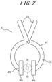
- FIG. 2 is a diagram illustrating an example of the configuration of the gripping structure 47 provided in the insulation clip 41 of FIG. 1 .
- the gripping structure 47 is provided with an arm portion 471, contact portions 472, and a gripping portion 473.
- the gripping structure 47 presses the pair of clip electrodes 40a and 40b against the cable sheath 82 by the arm portion 471 using an elastic force of a leaf spring or the like.
- the contact portions 472, which are ends of the arm portion 471 are connected to the clip electrodes 40a and 40b via adhesive portions 408 (see FIG. 3 ).
- the gripping portion 473 is manipulated by an operator to widen the length between the clip electrodes 40a and 40b.
- the clip electrode 40 has an electrode 402 that acquires electrical signals from the cable sheath 82 through an insulator portion 401.
- FIG. 3 is a cross-sectional view illustrating an example of the configuration of the clip electrode 40 of FIG. 2 .
- the clip electrode 40 includes the insulator portion 401, the electrode 402, insulator portions 403, a shield 404, insulator portions 405 and 406, and adhesive portions 408.
- the insulator portion 401 is an insulator in contact with the cable sheath 82 of the cable 80.
- the insulator portion 401 may be composed of, for example, rubber including ethylene propylene rubber, or the like.
- the electrode 402 is a conductor that acquires the electrical signals from the cable sheath 82 through the insulator portion 401.
- the electrode 402 outputs the electrical signals acquired from the cable sheath 82 to the apparatus main body 10 via the wiring 45.
- the insulator portions 403 are insulators that cover the periphery of the electrode 402 to prevent a short circuit.
- the shield 404 is a conductor that covers the electrode 402 over the insulator portions 403 to suppress the influences of external electromagnetic fields, external electromagnetic waves, and the like.
- the insulator portion 405 is an insulator that constitutes a housing of the clip electrode 40.
- the insulator portions 406 are insulators that prevent the cable 80 from moving relative to the insulator portion 401.
- the insulator portions 406 may be provided as projections on edges of the insulator portion 401.
- the insulator portions 403, 405, and 406 may be composed of a resin including acrylic, for example.
- the insulator portion 401, the electrode 402, the insulator portions 403, the shield 404, and the insulator portions 405 and 406 are adhered to each other by the adhesive portions 408.
- the adhesive portions 408 may be composed of, for example, an adhesive (binder) having insulating properties.
- the contact portion 472 of the gripping structure 47 is secured to an outer surface of the insulator portion 405 by the adhesive portion 408.
- the operator can manipulate the gripping portion 473 to widen the length between the clip electrodes 40a and 40b, attach the insulation clip 41 to the cable 80, and remove the insulation clip 41 from the cable 80.
- FIG. 4 is a diagram illustrating an example of the configuration of the measurement apparatus 1, which includes circuitry of the apparatus main body 10 of FIG. 1 .
- the apparatus main body 10 includes a circuit unit 71 and a control unit 72.
- the circuit unit 71 outputs electrical signals to the cable 80 and acquires responses from the cable 80.
- the control unit 72 controls operations of the circuit unit 71 and provides interfaces with the operator.
- the circuit unit 71 includes operational amplifiers 11 to 14, switches 21 and 22, a resistor 25, an injection terminal 31, and measurement terminals 35 to 37.
- the operational amplifiers 11 to 14 are electronic circuit modules of amplifiers with a non-inverting input terminal (+), an inverting input terminal (-), and an output terminal.
- the operational amplifiers 11 to 14 each amplify the potential difference between the non-inverting input terminal and the inverting input terminal at a specified amplification ratio (gain) and output the amplified potential difference from the output terminal.
- the operational amplifier 11 has a non-inverting input terminal connected to an output terminal of the operational amplifier 13 and the resistor 25, an inverting input terminal connected to an output terminal of the operational amplifier 14, and an output terminal connected to the measurement terminal 36.
- the operational amplifier 12 (I/V amplifier) has a non-inverting input terminal connected to the ground (GND), an inverting input terminal connected to the switch 21, and an output terminal connected to the measurement terminal 37.
- the operational amplifier 13 has a non-inverting input terminal connected to the injection terminal 31 and the measurement terminal 35, an inverting input terminal connected to the output terminal of the operational amplifier 14, and an output terminal connected to the non-inverting input terminal of the operational amplifier 11 and the resistor 25.
- the operational amplifier 14 (buffer amplifier) has a non-inverting input terminal connected to the switch 21 and the resistor 25, an inverting input terminal connected to the output terminal of the operational amplifier 14, and an output terminal connected to the inverting input terminal of each of the operational amplifiers 11, 13 and 14.
- the switch 21 is connected to the switch 22 at one end.
- the switch 21 connects either the inverting input terminal of the operational amplifier 12 or the non-inverting input terminal of the operational amplifier 14 and the resistor 25, to the switch 22 by a switching operation.
- the switch 22 is connected to the switch 21 at one end and to the clip electrode 40 at the other end.
- the switch 22 connects or opens between the switch 21 and the clip electrode 40 by a switching operation.
- the resistor 25 has a resistance value of R x .
- the injection terminal 31 outputs an injection current to the non-inverting input terminal of the operational amplifier 13.
- the injection current is an alternating current signal with a voltage V t and a frequency Ft (second frequency).
- the measurement terminals 35 to 37 output measurement signals V 1 to V 3 .
- the measurement signal V 1 output by the measurement terminal 35 is the same as the voltage V ⁇ of the injection current output by the injection terminal 31.
- the measurement signal V 2 output by the measurement terminal 36 is a current output from the output terminal of the operational amplifier 11.
- the measurement signal V 2 corresponds to a composite current in which the injection current is superimposed on a leakage current of the voltage V M to be measured.
- the measurement signal V 2 corresponds to a current flowing in the circuit unit 71 due to injection of the injection current into the circuit unit 71.
- the measurement signal V 3 output by the measurement terminal 37 is a current output from the output terminal of the operational amplifier 12.
- the measurement signal V 3 corresponds to the voltage V M of the leakage current, which has leaked out of the core wire 81 through the cable sheath 82 and the insulator portion 401.
- the control unit 72 includes a controller 721, a memory 722, an input interface 723, and an output interface 724.
- the controller 721 includes one or more processors.
- the controller 721 is communicatively connected to each of components constituting the apparatus main body 10, and controls operations of the entire measurement apparatus 1.
- the controller 721 may control switching of the switches 21 and 22, input of the injection current from the injection terminal 31, voltage measurement at the measurement terminals 35 to 37, analysis of voltage measurement values, and the like.
- the memory 722 includes one or more memory devices.
- the memory 722 stores any information used in the operations of the measurement apparatus 1.
- the measurement apparatus 1 may store information regarding measurement of the voltage V M to be measured applied to the core wire 81.
- the input interface 723 includes one or more input interfaces that accept input operations by the operator and acquire input information based on the operations by the operator.
- the input interface 723 includes a physical key, a capacitive key, a touch screen integrated with a display of the output interface 724, and the like, but is not limited to these.
- the output interface 724 includes one or more output interfaces that output information to the operator and notify the operator of the information.
- the output interface 724 is a display that outputs information as images, or the like, but is not limited to this.
- the apparatus main body 10 includes the circuit unit 71 and the control unit 72, but some of functions thereof may be realized by an external apparatus.
- the apparatus main body 10 measures the voltage V M to be measured applied to the core wire 81 and the phase ⁇ M of the leakage current, based on an electrical signal acquired from one clip electrode 40 will be described below.
- the measurement apparatus 1 can measure the voltage V M to be measured and the phase ⁇ M of the leakage current for each clip electrode 40 by providing the circuit unit 71 for each clip electrode 40.
- the voltage V M to be measured is applied from a power supply 84 to the core wire 81.
- the voltage V M to be measured is an alternating current signal with a frequency F M (first frequency), the voltage V M , and the phase ⁇ M .
- F M first frequency
- I M current effective value
- the resistance component 87 and the capacitance component 88 of the cable sheath 82 also include a contribution of a resistance component and a capacitance component of the insulator portion 401.
- the measurement terminal 36 outputs the measurement signal V 2 with a voltage V 2 proportional to the magnitude of such a composite current.
- the measurement terminal 35 outputs the measurement signal V 1 that is the same as the voltage V ⁇ of the injection current.
- the measurement apparatus 1 calculates, based on the voltages V 1 and V 2 , an injection active power Ix_Active, which is equivalent to an active power of the composite current, and an injection reactive power Ix_Reactive, which is equivalent to a reactive power of the composite current.
- the measurement apparatus 1 can determine the phase ⁇ M of the leakage current relative to the injection current, based on the ratio between the injection active power Ix_Active and the injection reactive power Ix_Reactive.
- the phase ⁇ M corresponds to the phase of the voltage V M to be measured, relative to the voltage V t caused by the injection current.
- the measurement apparatus 1 can measure the voltage V M to be measured and the phase ⁇ M of the leakage current.
- the measurement apparatus 1 may measure the measurement signal V 1 at the measurement terminal 35 and the measurement signal V 2 at the measurement terminal 36 when the switch 21 is connected to the resistor 25 side and the switch 22 is open.
- the measurement apparatus 1 may calculate an offset active power Iofs_Active, which is equivalent to an active power of the voltage V 2 when the influence of the voltage V M to be measured is excluded, and an offset reactive power Iofs_Reactive, which is equivalent to a reactive power thereof.
- the measurement apparatus 1 may calculate an active power I_Active (measured active power), in which the offset active power Iofs_Active is offset from the injection active power Ix_Active, and a reactive power I_Reactive (measured reactive power), in which the offset reactive power Iofs_Reactive is offset from the injection reactive power Ix_Reactive.
- the active power I_Active and the reactive power I_Reactive are obtained by the following equations (1) and (2).
- I_Active Ix_Active ⁇ Iofs_Active
- I_Reactive Ix_Reactive ⁇ Iofs_Reactive
- the measurement apparatus 1 may calculate the voltage V M to be measured and the phase ⁇ M of the leakage current, using the active power I_Active and the reactive power I_Reactive calculated as described above. This allows the measurement apparatus 1 to acquire the voltage V M to be measured and the phase ⁇ M of the leakage current with higher accuracy, with reduced influences of measurement environment, internal leakages, and the like.
- the measurement apparatus 1 may measure, at the measurement terminal 37, the measurement signal V 3 of the operational amplifier 12 with the switch 21 connected to the operational amplifier 12 side and the switch 22 connected.
- the measurement apparatus 1 may directly measure the leakage current I M (current effective value: I M ) of the voltage V M to be measured, based on the voltage V 3 .
- the measurement apparatus 1 may calculate the voltage V M to be measured, based on the active power I_Active, the reactive power I_Reactive, the current effective value I M of the leakage current I M , the frequency Ft of the voltage V ⁇ of the injection current, and the frequency F M of the voltage V M to be measured, in addition to the leakage current I M measured as described above.
- the measurement apparatus 1 can acquire the voltage V M to be measured with higher accuracy by provision of the measurement terminal 37 for directly measuring the leakage current I M and the switch 21 for connecting the clip electrode 40 to the measurement terminal 37.
- the relationship between the active power I_Active and reactive power I_Reactive and the aforementioned resistance component 87 and capacitance component 88 of the cable sheath 82 (including the insulator portion 401) will be described below.
- FIG. 5 is a diagram explaining an example of a measurement sequence by the measurement apparatus 1.
- the horizontal axis indicates time
- the vertical axis indicates voltage.
- the graph 101 represents a variation of the voltage V 1 of the measurement signal V 1 with time.
- the graph 102 represents a variation of the voltage V 2 of the measurement signal V 2 with time.
- the measurement apparatus 1 acquires, as the offset active power Iofs_Active, the average of a multiplication of an instantaneous value of the voltage V 1 and an instantaneous value of the voltage V 2 .
- the measurement apparatus 1 calculates, as the offset reactive power Iofs_Reactive, the average of a multiplication of an instantaneous value of the voltage V 1 with a phase shifted by 90 degrees and an instantaneous value of the voltage V 2 .
- the offset active power Iofs_Active and the offset reactive power Iofs_Reactive are equivalent to an active power and a reactive power in the circuit unit 71 that are measured without a contribution of the leakage current from the core wire 81, to which the voltage V M to be measured is applied, with application of the injection current in the circuit unit 71.
- the measurement apparatus 1 acquires, as the injection active power Ix_Active, the average of a multiplication of an instantaneous value of the voltage V 1 and an instantaneous value of the voltage V 2 .
- the measurement apparatus 1 calculates, as the injection reactive power Ix_Reactive, the average of a multiplication of an instantaneous value of the voltage V 1 with a phase shifted by 90 degrees and an instantaneous value of the voltage V 2 .
- the injection active power Ix_Active and the injection reactive power Ix_Reactive are equivalent to an active power and a reactive power in the circuit unit 71 that are measured with a contribution of the leakage current I M from the core wire 81, to which the voltage V M to be measured is applied, with application of the injection current in the circuit unit 71.
- the measurement apparatus 1 measures the leakage current I M of the voltage V M to be measured. Specifically, the measurement apparatus 1 connects the switch 21 to the operational amplifier 12 side and outputs the leakage current I M of the voltage V M to be measured to the operational amplifier 12. The operational amplifier 12 amplifies the leakage current I M and outputs the amplified leakage current I M to the measurement terminal 37. The measurement apparatus 1 acquires the measurement signal V 3 measured at the measurement terminal 37, which is a current corresponding to the leakage current I M . In FIG. 5 , a graph 104 represents a variation of the voltage V 3 of the measurement signal V 3 with time.
- the measurement apparatus 1 acquires the current effective value I M of the leakage current I M measured in this manner.
- the measurement apparatus 1 acquires the voltage V 3 of the leakage current I M of the voltage V M to be measured that has leaked out of the core wire 81 through the insulator (the cable sheath 82 and the insulator portion 401) without a contribution of the injection current, and acquires, based on the voltage V 3 , the current effective value of the leakage current I M .
- the measurement apparatus 1 acquires the voltage V M to be measured and phase ⁇ M based on the information acquired in the measurement periods T1 to T3. First, the measurement apparatus 1 calculates the active power I_Active from the equation (1) based on the injection active power Ix_Active and the offset active power Iofs_Active acquired in the measurement periods T1 and T2. Similarly, the measurement apparatus 1 calculates the reactive power I_Reactive from the equation (2) based on the injection reactive power Ix_Reactive and the offset reactive power Iofs_Reactive acquired in the measurement periods T1 and T2.
- the measurement apparatus 1 acquires the voltage V M to be measured based on the active power I_Active, the reactive power I_Reactive, the voltage V ⁇ and frequency Ft of the injection current, the frequency F M of the voltage V M to be measured, and the current effective value I M of the leakage current I M .
- a value I_Reactive' is calculated by multiplying the reactive power I_Reactive by the ratio between the frequency F M of the voltage V M to be measured and the frequency Ft of voltage V ⁇ of the injection current.
- I_Reactive ′ I_Reactive ⁇ F M / F t
- an apparent power I_Apparent is calculated by the following equation (5).
- I_Apparent I_Active 2 + I_Reactive ′ 2 1 / 2 / V t
- ((I_Active) 2 + (I_Reactive') 2 ) 1/2 corresponds to the apparent power.
- the measurement apparatus 1 calculates the apparent power I_Apparent by the equation (5), and then calculates the voltage V M to be measured by the following equation (6).
- V M I M / I _ Apparent ⁇ V t
- the calculations in the equations (4) to (6) correspond to calculating the voltage V M to be measured by back-calculating the voltage level of the measurement signal V 3 from the resistance component 87 and the capacitance component 88, which are obtained from the measurement signals V 1 and V 2 .
- the measurement apparatus 1 outputs the voltage V M to be measured and the phase ⁇ M of the leakage current obtained as described above.
- the measurement apparatus 1 may display the voltage V M and the phase ⁇ M on the output interface 724 or store the voltage V M and the phase ⁇ M in the memory 722.
- the measurement apparatus 1 injects the injection current into the cable 80 to which the voltage V M to be measured is applied, and measures the composite current (voltage V 2 ), which is a combination of the injection current and the leakage current I M of the voltage V M to be measured that has leaked out through the cable sheath 82.
- the measurement apparatus 1 acquires the phase ⁇ M of the voltage V M to be measured, relative to the voltage V ⁇ of the injection current, using the ratio between the reactive power and the active power.
- the measurement apparatus 1 also calculates the apparent power I_Apparent, based on the reactive power and active power, the ratio between the frequency F M of the voltage V M to be measured and the frequency Ft of the voltage V ⁇ of the injection current, and the voltage V ⁇ of the injection current.
- the measurement apparatus 1 calculates the voltage V M to be measured from the leakage current I M , the apparent power I_Apparent, and the voltage V ⁇ of the injection current.
- the measurement apparatus 1 injects, into the cable sheath 82, the injection current with the frequency Ft different from the frequency F M of the voltage V M to be measured.
- the measurement apparatus 1 can measure the voltage V M to be measured and the phase ⁇ M from over the cable sheath 82 with the simple configuration by distinguishing, based on the frequencies, the voltage V M to be measured from the voltage V ⁇ of the injection current, while the cable is in a live wire condition.
- the measurement apparatus 1 also measures the offset active power Iofs_Active and the offset reactive power Iofs_Reactive with the switch 22 disconnected, corrects the injection active power Ix_Active and the injection reactive power Ix_Reactive, and then calculates the voltage V M to be measured and the phase ⁇ M .
- the offset active power Iofs_Active and the offset reactive power Iofs_Reactive reflect a power consumed by the capacitance component and the insulation resistance component in the circuit unit 71. Therefore, the measurement apparatus 1 can measure the voltage V M to be measured and the phase ⁇ M with higher accuracy by excluding the influences of leakages, environment, and the like in the circuit unit 71.
- the measurement apparatus 1 directly measures the leakage current I M of the voltage V M to be measured by switching the switch 21, and measures the voltage V M to be measured based on the measurement value. Therefore, the measurement apparatus 1 can measure the voltage V M to be measured and the phase ⁇ M with higher accuracy by excluding the influences of resistance leakages and the like in the circuit unit 71.
- FIG. 5 illustrates an example in which the offset active power Iofs_Active and the offset reactive power Iofs_Reactive are calculated in the measurement period T1, then the injection active power Ix_Active and the injection reactive power Ix_Reactive are calculated in the measurement period T2, and then the leakage current I M is measured in the measurement period T3.
- the measurement sequence is arbitrary and is not limited to that illustrated in FIG. 5 .
- the measurement apparatus 1 described with reference to FIGS. 1 to 5 may be applied, for example, to an apparatus that measures the amount of electricity in a three-wire power transmission circuit.
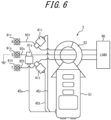
- FIG. 6 is a diagram illustrating an example of an apparatus 2 that measures a live wire insulation resistance, to which the measurement apparatus 1 of FIG. 1 is applied.
- the apparatus 2 is an example of a configuration in which the measurement apparatus 1 according to this embodiment is applied to a clamp sensor.
- the clamp sensor is an apparatus that measures, using electromagnetic induction action, a voltage to be measured based on a measurement value of a magnetic field generated in a magnetic core located around conductors.
- the apparatus 2 includes a main body 51, a clamp 52, insulation clips 41 (41r, 41s, 41t), and wiring 45 (45r, 45s, 45t).
- the apparatus 2 has the same configuration as the insulation clip 41 and the wiring 45 described with reference to FIGS. 2 and 3 for each of R, S, and T.
- the main body 51 has the same configuration as the apparatus main body 10 described with reference to FIG. 4 for each of R, S, and T.
- the main body 51 also has a configuration for measuring a current detected at the clamp 52 by electromagnetic induction action
- a power is supplied from terminals 91 (91r, 91s, 91t) to a load 90 through three-phase three-wire cables 92 (92r, 92s, 92t).
- the clamp 52 is used, for example, to measure a leakage current in a switchboard circuit.
- the apparatus 2 can measure a voltage to be measured applied to each cable 92 and a phase thereof in a non-contact manner, by clipping the cables 92 (92r, 92s, 92t) with the insulation clips 41 (41r, 41s, 41t), respectively.
- the apparatus 2 constitutes a live wire insulation resistance Ior measurement device with such a non-contact voltage probe configuration. That is, a leakage current Io measured at the clamp 52 is a composite value of a capacitive leakage and a resistive leakage. Therefore, the apparatus 2 can extract only the resistive leakage from the difference between the phase of the voltage to be measured that has been measured by the insulation clip 41 and the phase of the current Io that has been measured by the clamp 52. The apparatus 2 can also obtain the value of the insulation resistance from the value of the voltage to be measured that has been measured by the insulation clip 41 and the leakage current of the resistance component of Io measured by the clamp 52. Since the apparatus 2 can make these measurements in a non-contact manner without directly touching live wires, an operator can work safely in hazardous switchboard operations.
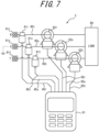
- FIG. 7 is a diagram illustrating an example of a wattmeter 3 to which the measurement apparatus 1 of FIG. 1 is applied.
- the wattmeter 3 includes a main body 61, clamps 62 (62r, 62s, 62t), wiring 65 (65r, 65s, 65t), insulation clips 41 (41r, 41s, 41t), and wiring 45 (45r, 45s, 45t).
- the wattmeter 3 in FIG. 7 differs from the apparatus 2 in FIG. 6 in that the wattmeter 3 has not only the insulation clips 41 and the wiring 45, but also the clamps 62 and the wiring 65 for each of R, S, and T. According to the wattmeter 3 as illustrated in FIG.
- a clamped wattmeter or a direct current-measuring wattmeter can measure phases and voltages in a non-contact manner, in addition to a load current measurement and a power measurement. Since the wattmeter 3 can also make these measurements without contact to live wires, an operator can work safely in hazardous switchboard operations.
- the measurement apparatus 1 can be applied to wattmeters, voltmeters, and the like, in addition to live wire insulation measurements.
- the measurement apparatus 1 can be applied to voltage measurements in hazardous locations and devices for safely measuring voltage in outdoor high-voltage facilities and the like, such as digital multimeters and electric meters.
- the measurement apparatus 1 can identify the resistance component 87 and the capacitance component 88 of the cable sheath 82 in a live wire condition, with the resistance component 87 and the capacitance component 88 distinguished from the signals to be measured, by injecting the injection current with the frequency Ft different from the frequency F M of the voltage V M to be measured.
- the measurement apparatus 1 can also measure the voltage V M to be measured and the phase ⁇ M , based on the signals acquired through the cable sheath 82 and the insulator portion 401 by clipping the insulation clip 41 from over the cable sheath 82.
- the operator can safely proceed with maintenance work without clipping live wires.
- the measurement apparatus 1 has a simple circuit configuration as illustrated in FIG. 4 . Therefore, the measurement apparatus 1 can be realized with a relatively inexpensive configuration.
- the present disclosure is not limited to the embodiment described above.
- a plurality of blocks described in the block diagrams may be integrated, or one block may be divided.
- Other changes are possible to the extent of not departing from the intent of the present disclosure.
Landscapes
- Physics & Mathematics (AREA)
- General Physics & Mathematics (AREA)
- Engineering & Computer Science (AREA)
- Power Engineering (AREA)
- Measurement Of Current Or Voltage (AREA)
- Measurement Of Resistance Or Impedance (AREA)
- Testing Of Short-Circuits, Discontinuities, Leakage, Or Incorrect Line Connections (AREA)
Abstract
Description
- This application claims priority to
Japanese Patent Application No. 2023-082535, filed on May 18, 2023 - The present disclosure relates to a measurement apparatus and a measurement method.
- With the development of 24-hour operation, systemization, and the like of equipment, there is a growing demand for maintenance while the equipment is still in operation. As part of such equipment maintenance, metal clips are connected to screws or other parts, which constitute live wire sections, in switchboards or the like to measure the voltage, phase, and the like of the live wire sections.
- The live wire sections of the switchboards do not have a structure for clipping, and are often dense in small areas. Therefore, the method of connecting a clip to a live wire section and measuring a voltage or the like may cause a risk of electric shock to an operator. There may also be risks of a short circuit in a power supply at the time of clipping, a short circuit due to the clip falling off, a loss of measurement data due to the clip falling off, and the like.
- Patent Literature (PTL) 1 describes a non-contact voltage measurement apparatus that measures an alternating voltage, which is applied to a core wire of an electric wire, through an insulator in contact with the core wire. In the configuration of
PTL 1, a coupling capacitance is obtained based on an input signal, which is divided between the insulator and the coupling capacitance between electrodes, by varying the capacitance of a reference capacitor provided in advance, and the alternating voltage is measured based on the value of this coupling capacitance. According to this configuration, the voltage to be measured applied to the core wire, or the like can be measured from over a cable sheath, not from a live wire section. Therefore, the risks of electric shock to an operator, a short circuit, a loss of measurement data, and the like can be reduced. - PTL 1:
JP 4251961 B2 - However, the configuration of
PTL 1 leaves room for improvement in measurement accuracy in measuring an applied voltage or the like through an insulator in contact with a core wire of a sheathed electric wire. - It would be helpful to enable measurement of a physical quantity of a voltage to be measured applied to a core wire, from over a cable sheath with higher accuracy.
- A measurement apparatus according to some embodiments includes
- (1) a controller configured to:
- inject an injection current with a second frequency into a core wire through an insulator, a voltage to be measured, with a first frequency, being applied to the core wire;
- acquire a composite current that is composed of the injection current and a leakage current of the voltage to be measured having leaked through the insulator;
- calculate a measured active power and a measured reactive power based on the composite current, the measured active power and the measured reactive power being equivalent to an active power and a reactive power based on a contribution of the voltage to be measured;
- calculate the voltage to be measured, based on the measured active power, the measured reactive power, the first frequency, the second frequency, a voltage of the injection current, and a current effective value of the leakage current; and
- output the voltage to be measured.
- Thus, the measurement apparatus measures, based on the signal acquired through the insulator, the leakage current flowing, through the sheath, out of the core wire to which the voltage to be measured is applied, rather than acquiring a signal directly from the core wire to which the voltage to be measured is applied, thus enabling measurement of a physical quantity of the voltage to be measured from over the cable sheath. The measurement apparatus injects the injection current with the second frequency different from the first frequency of the leakage current flowing, through the sheath, out of the core wire to which the voltage to be measured is applied, and measures the voltage to be measured, based on the active power and the reactive power based on the contribution of the voltage to be measured. Therefore, the measurement apparatus can measure the voltage to be measured, from over the cable sheath with higher accuracy with a simple configuration by distinguishing, based on the frequencies, the leakage current flowing, through the sheath, out of the core wire to which the voltage to be measured is applied, from the injection current, while the cable is in a live wire condition.
- According to one embodiment,
(2) in the measurement apparatus according to (1), the controller may be configured to: - calculate an apparent power based on the measured active power, the measured reactive power, the first frequency, and the second frequency, the apparent power corresponding to the measured active power and the measured reactive power; and
- calculate the voltage to be measured, based on the calculated apparent power, the voltage of the injection current, and the current effective value of the leakage current.
- Thus, the measurement apparatus calculates the apparent power corresponding to the measured active power and the measured reactive power, and calculates the voltage to be measured, thus enabling measurement of the voltage to be measured with higher accuracy according to a resistance component and a capacitance component of the insulator.
- According to one embodiment,
(3) in the measurement apparatus according to (1) or (2), the controller may be configured to: - calculate a phase of the leakage current, relative to the injection current, based on the ratio between the calculated measured active power and the calculated measured reactive power; and
- further output the calculated phase of the leakage current.
- Thus, the measurement apparatus can measure, with higher accuracy, not only the voltage to be measured but also the phase of the leakage current having leaked through the insulator due to the voltage to be measured.
- According to one embodiment,
(4) in the measurement apparatus according to any one of (1) to (3), the controller may be configured to: - measure an injection active power and an injection reactive power equivalent to an active power and a reactive power in a circuit unit that are measured with a contribution of the leakage current with application of the injection current in the circuit unit;
- measure an offset active power and an offset reactive power equivalent to an active power and a reactive power in the circuit unit that are measured without a contribution of the leakage current with application of the injection current in the circuit unit;
- calculate, as the measured active power, a power in which the offset active power is offset from the injection active power; and
- calculate, as the measured reactive power, a power in which the offset reactive power is offset from the injection reactive power.
- Thus, the measurement apparatus measures the measured active power and the measured reactive power by offsetting the offset active power and the offset reactive power, which are measured without the contribution of the leakage current, from the injection active power and the injection reactive power, and measures the voltage to be measured, using the measured active power and the measured reactive power. Therefore, the measurement apparatus can measure a physical quantity of the voltage to be measured with higher accuracy, with reduced influences of measurement environment, internal leakages, and the like.
- According to one embodiment,
(5) in the measurement apparatus according to any one of (1) to (4), the controller may be configured to: - acquire a voltage of the leakage current of the voltage to be measured that has leaked out of the core wire through the insulator without a contribution of the injection current; and
- acquire the current effective value of the leakage current, based on the acquired voltage of the leakage current.
- Thus, the measurement apparatus acquires the current effective value, based on the measurement value of the leakage current measured without the contribution of the injection current. Therefore, the measurement apparatus can measure a physical quantity of the voltage to be measured with higher accuracy, using the more accurate current effective value.
- A measurement method according to some embodiments is
(6) a measurement method by a measurement apparatus including a controller, the measurement method including: - injecting, by the controller, an injection current with a second frequency into a core wire through an insulator, a voltage to be measured, with a first frequency, being applied to the core wire;
- acquiring, by the controller, a composite current that is composed of the injection current and a leakage current of the voltage to be measured having leaked through the insulator;
- calculating, by the controller, a measured active power and a measured reactive power based on the composite current, the measured active power and the measured reactive power being equivalent to an active power and a reactive power based on a contribution of the voltage to be measured;
- calculating, by the controller, the voltage to be measured, based on the measured active power, the measured reactive power, the first frequency, the second frequency, a voltage of the injection current, and a current effective value of the leakage current; and
- outputting, by the controller, the voltage to be measured.
- Thus, the measurement method measures, based on the signal acquired through the insulator, the leakage current flowing, through the sheath, out of the core wire to which the voltage to be measured is applied, rather than acquiring a signal directly from the core wire to which the voltage to be measured is applied, thus enabling measurement of a physical quantity of the voltage to be measured from over the cable sheath. The measurement method injects the injection current with the second frequency different from the first frequency of the leakage current flowing, through the sheath, out of the core wire to which the voltage to be measured is applied, and measures the voltage to be measured, based on the active power and the reactive power based on the contribution of the voltage to be measured. Therefore, the measurement method can measure the voltage to be measured, from over the cable sheath with higher accuracy with a simple configuration by distinguishing, based on the frequencies, the leakage current flowing, through the sheath, out of the core wire to which the voltage to be measured is applied, from the injection current, while the cable is in a live wire condition.
- According to one embodiment,
(7) the measurement method according to (6), may include: - calculating, by the controller, an apparent power based on the measured active power, the measured reactive power, the first frequency, and the second frequency, the apparent power corresponding to the measured active power and the measured reactive power; and
- calculating, by the controller, the voltage to be measured, based on the calculated apparent power, the voltage of the injection current, and the current effective value of the leakage current.
- Thus, the measurement method calculates the apparent power corresponding to the measured active power and the measured reactive power, and calculates the voltage to be measured, thus enabling measurement of the voltage to be measured with higher accuracy according to a resistance component and a capacitance component of the insulator.
- According to one embodiment,
(8) the measurement method according to (6) or (7), may include: - calculating, by the controller, a phase of the leakage current, relative to the injection current, based on the ratio between the calculated measured active power and the calculated measured reactive power; and
- further outputting, by the controller, the calculated phase of the leakage current.
- Thus, the measurement method can measure, with higher accuracy, not only the voltage to be measured but also the phase of the leakage current having leaked through the insulator due to the voltage to be measured.
- According to one embodiment,
(9) the measurement method according to any one of (6) to (8), may include: - measuring, by the controller, an injection active power and an injection reactive power equivalent to an active power and a reactive power in a circuit unit that are measured with a contribution of the leakage current with application of the injection current in the circuit unit;
- measuring, by the controller, an offset active power and an offset reactive power equivalent to an active power and a reactive power in the circuit unit that are measured without a contribution of the leakage current with application of the injection current in the circuit unit;
- calculating, by the controller, as the measured active power, a power in which the offset active power is offset from the injection active power; and
- calculating, by the controller, as the measured reactive power, a power in which the offset reactive power is offset from the injection reactive power.
- Thus, the measurement method measures the measured active power and the measured reactive power by offsetting the offset active power and the offset reactive power, which are measured without the contribution of the leakage current, from the injection active power and the injection reactive power, and measures the voltage to be measured, using the measured active power and the measured reactive power. Therefore, the measurement method can measure a physical quantity of the voltage to be measured with higher accuracy, with reduced influences of measurement environment, internal leakages, and the like.
- According to one embodiment,
(10) the measurement method according to any one of (6) to (9), may include: - acquiring, by the controller, a voltage of the leakage current of the voltage to be measured that has leaked out of the core wire through the insulator without a contribution of the injection current; and
- acquiring, by the controller, the current effective value of the leakage current, based on the acquired voltage of the leakage current.
- Thus, the measurement method acquires the current effective value, based on the measurement value of the leakage current measured without the contribution of the injection current. Therefore, the measurement method can measure a physical quantity of the voltage to be measured with higher accuracy, using the more accurate current effective value.
- According to the present disclosure, a physical quantity of a voltage to be measured applied to a core wire can be measured from over a cable sheath with higher accuracy.
- In the accompanying drawings:
-
FIG. 1 is a diagram illustrating an example of the configuration of a measurement apparatus according to an embodiment; -
FIG. 2 is a diagram illustrating an example of the configuration of a gripping structure provided in an insulation clip ofFIG. 1 ; -
FIG. 3 is a cross-sectional view illustrating an example of the configuration of a clip electrode ofFIG. 2 ; -
FIG. 4 is a diagram illustrating an example of the configuration of the measurement apparatus, which includes circuitry of an apparatus main body ofFIG. 1 ; -
FIG. 5 is a diagram explaining an example of a measurement sequence by the measurement apparatus; -
FIG. 6 is a diagram illustrating an example of an apparatus that measures a live wire insulation resistance, to which the measurement apparatus ofFIG. 1 is applied; and -
FIG. 7 is a diagram illustrating an example of a wattmeter to which the measurement apparatus ofFIG. 1 is applied. - As a configuration according to a comparative example, PTL 1 (claim 1) states
- "A non-contact voltage measurement apparatus configured to measure an alternating voltage, which is applied to a core wire of an electric wire, through an insulator in contact with the core wire, the non-contact voltage measurement apparatus including:
- a first electrode configured to capture an input signal through the insulator;
- a voltage measurement means configured to obtain a coupling capacitance between electrodes, based on the input signal divided between the insulator and the coupling capacitance by varying the capacitance of a reference capacitor provided in advance, and obtain the alternating voltage based on the value of the coupling capacitance;
- a second electrode configured to detect, through the insulator, an alternating voltage that has the same phase as the alternating voltage, the second electrode being disposed a small distance away from the electric wire so as to be coupled to the electric wire only by a capacitance component and not to contact with a resistance component;
- a phase difference detection means configured to detect the phase difference between the alternating voltage obtained by the voltage measurement means and the alternating voltage obtained by the second electrode; and
- a correction means configured to correct the alternating current obtained by the voltage measurement means by input of the phase difference obtained by the phase difference detection means and the voltage from the voltage measurement means."
- The capacitance of the insulator that sheathes the electric wire is extremely small and may vary greatly depending on measurement conditions such as temperature and humidity. Therefore, the configuration of the comparative example, which measures the alternating voltage based on the capacitance of the insulator, has room for improvement in measurement accuracy.
- An embodiment of the present disclosure will be described below with reference to the drawings. In the drawings, portions having the same configuration or function are denoted by the same reference numerals. In the description of this embodiment, duplicate descriptions of the same portions may be omitted or simplified as appropriate.
-
FIG. 1 is a diagram illustrating an example of the configuration of ameasurement apparatus 1 according to the embodiment. Themeasurement apparatus 1 measures a voltage VM to be measured applied to acable 80, and the phase θM of a leakage current IM flowing out through a sheath. Thecable 80 includes acore wire 81, to which the voltage VM to be measured is applied, and acable sheath 82, which is an insulator sheathing thecore wire 81. Themeasurement apparatus 1 includes an apparatusmain body 10, aninsulation clip 41, andwiring 45. - The
insulation clip 41 contacts thecable sheath 82, and acquires the current IM (current effective value of leakage current: IM) flowing out through the sheath from thecore wire 81 to which the voltage VM to be measured is applied. As illustrated inFIG. 1 , theinsulation clip 41 contacts thecable sheath 82 of thecable 80 by a pair ofclip electrodes cable sheath 82. Theclip electrodes clip electrodes 40". - The
insulation clip 41 may be provided with a grippingstructure 47 that presses theclip electrodes 40 ofFIG. 1 against thecable 80.FIG. 2 is a diagram illustrating an example of the configuration of the grippingstructure 47 provided in theinsulation clip 41 ofFIG. 1 . The grippingstructure 47 is provided with anarm portion 471,contact portions 472, and agripping portion 473. The grippingstructure 47 presses the pair ofclip electrodes cable sheath 82 by thearm portion 471 using an elastic force of a leaf spring or the like. In this embodiment, thecontact portions 472, which are ends of thearm portion 471, are connected to theclip electrodes FIG. 3 ). The grippingportion 473 is manipulated by an operator to widen the length between theclip electrodes - The
clip electrode 40 has anelectrode 402 that acquires electrical signals from thecable sheath 82 through aninsulator portion 401.FIG. 3 is a cross-sectional view illustrating an example of the configuration of theclip electrode 40 ofFIG. 2 . Theclip electrode 40 includes theinsulator portion 401, theelectrode 402,insulator portions 403, ashield 404,insulator portions adhesive portions 408. - The
insulator portion 401 is an insulator in contact with thecable sheath 82 of thecable 80. Theinsulator portion 401 may be composed of, for example, rubber including ethylene propylene rubber, or the like. Theelectrode 402 is a conductor that acquires the electrical signals from thecable sheath 82 through theinsulator portion 401. Theelectrode 402 outputs the electrical signals acquired from thecable sheath 82 to the apparatusmain body 10 via thewiring 45. - The
insulator portions 403 are insulators that cover the periphery of theelectrode 402 to prevent a short circuit. Theshield 404 is a conductor that covers theelectrode 402 over theinsulator portions 403 to suppress the influences of external electromagnetic fields, external electromagnetic waves, and the like. Theinsulator portion 405 is an insulator that constitutes a housing of theclip electrode 40. Theinsulator portions 406 are insulators that prevent thecable 80 from moving relative to theinsulator portion 401. Theinsulator portions 406 may be provided as projections on edges of theinsulator portion 401. Theinsulator portions - The
insulator portion 401, theelectrode 402, theinsulator portions 403, theshield 404, and theinsulator portions adhesive portions 408. Theadhesive portions 408 may be composed of, for example, an adhesive (binder) having insulating properties. - In the example of
FIGS. 2 and3 , thecontact portion 472 of the grippingstructure 47 is secured to an outer surface of theinsulator portion 405 by theadhesive portion 408. Thus, the operator can manipulate thegripping portion 473 to widen the length between theclip electrodes insulation clip 41 to thecable 80, and remove theinsulation clip 41 from thecable 80. -
FIG. 4 is a diagram illustrating an example of the configuration of themeasurement apparatus 1, which includes circuitry of the apparatusmain body 10 ofFIG. 1 . As illustrated inFIG. 4 , the apparatusmain body 10 includes acircuit unit 71 and acontrol unit 72. Thecircuit unit 71 outputs electrical signals to thecable 80 and acquires responses from thecable 80. Thecontrol unit 72 controls operations of thecircuit unit 71 and provides interfaces with the operator. - The
circuit unit 71 includes operational amplifiers 11 to 14, switches 21 and 22, aresistor 25, aninjection terminal 31, andmeasurement terminals 35 to 37. - The operational amplifiers 11 to 14 are electronic circuit modules of amplifiers with a non-inverting input terminal (+), an inverting input terminal (-), and an output terminal. The operational amplifiers 11 to 14 each amplify the potential difference between the non-inverting input terminal and the inverting input terminal at a specified amplification ratio (gain) and output the amplified potential difference from the output terminal. The operational amplifier 11 has a non-inverting input terminal connected to an output terminal of the
operational amplifier 13 and theresistor 25, an inverting input terminal connected to an output terminal of theoperational amplifier 14, and an output terminal connected to themeasurement terminal 36. The operational amplifier 12 (I/V amplifier) has a non-inverting input terminal connected to the ground (GND), an inverting input terminal connected to theswitch 21, and an output terminal connected to themeasurement terminal 37. Theoperational amplifier 13 has a non-inverting input terminal connected to theinjection terminal 31 and themeasurement terminal 35, an inverting input terminal connected to the output terminal of theoperational amplifier 14, and an output terminal connected to the non-inverting input terminal of the operational amplifier 11 and theresistor 25. The operational amplifier 14 (buffer amplifier) has a non-inverting input terminal connected to theswitch 21 and theresistor 25, an inverting input terminal connected to the output terminal of theoperational amplifier 14, and an output terminal connected to the inverting input terminal of each of theoperational amplifiers - The
switch 21 is connected to theswitch 22 at one end. Theswitch 21 connects either the inverting input terminal of the operational amplifier 12 or the non-inverting input terminal of theoperational amplifier 14 and theresistor 25, to theswitch 22 by a switching operation. Theswitch 22 is connected to theswitch 21 at one end and to theclip electrode 40 at the other end. Theswitch 22 connects or opens between theswitch 21 and theclip electrode 40 by a switching operation. Theresistor 25 has a resistance value of Rx. - The
injection terminal 31 outputs an injection current to the non-inverting input terminal of theoperational amplifier 13. The injection current is an alternating current signal with a voltage Vt and a frequency Ft (second frequency). - The
measurement terminals 35 to 37 output measurement signals V1 to V3. The measurement signal V1 output by themeasurement terminal 35 is the same as the voltage Vε of the injection current output by theinjection terminal 31. The measurement signal V2 output by themeasurement terminal 36 is a current output from the output terminal of the operational amplifier 11. When theswitch 21 is connected to theresistor 25 side and theswitch 22 is connected, the measurement signal V2 corresponds to a composite current in which the injection current is superimposed on a leakage current of the voltage VM to be measured. When theswitch 22 is open, the measurement signal V2 corresponds to a current flowing in thecircuit unit 71 due to injection of the injection current into thecircuit unit 71. The measurement signal V3 output by themeasurement terminal 37 is a current output from the output terminal of the operational amplifier 12. When theswitch 21 is connected to the operational amplifier 12 side, the measurement signal V3 corresponds to the voltage VM of the leakage current, which has leaked out of thecore wire 81 through thecable sheath 82 and theinsulator portion 401. - The
control unit 72 includes acontroller 721, amemory 722, aninput interface 723, and anoutput interface 724. - The
controller 721 includes one or more processors. Thecontroller 721 is communicatively connected to each of components constituting the apparatusmain body 10, and controls operations of theentire measurement apparatus 1. For example, thecontroller 721 may control switching of theswitches injection terminal 31, voltage measurement at themeasurement terminals 35 to 37, analysis of voltage measurement values, and the like. - The
memory 722 includes one or more memory devices. Thememory 722 stores any information used in the operations of themeasurement apparatus 1. For example, themeasurement apparatus 1 may store information regarding measurement of the voltage VM to be measured applied to thecore wire 81. - The
input interface 723 includes one or more input interfaces that accept input operations by the operator and acquire input information based on the operations by the operator. For example, theinput interface 723 includes a physical key, a capacitive key, a touch screen integrated with a display of theoutput interface 724, and the like, but is not limited to these. - The
output interface 724 includes one or more output interfaces that output information to the operator and notify the operator of the information. For example, theoutput interface 724 is a display that outputs information as images, or the like, but is not limited to this. - In this embodiment, the apparatus
main body 10 includes thecircuit unit 71 and thecontrol unit 72, but some of functions thereof may be realized by an external apparatus. - For the sake of simplicity of explanation, an example in which the apparatus
main body 10 measures the voltage VM to be measured applied to thecore wire 81 and the phase θM of the leakage current, based on an electrical signal acquired from oneclip electrode 40 will be described below. When electrical signals are received from a plurality ofclip electrodes 40, as illustrated inFIGS. 1 and2 , themeasurement apparatus 1 can measure the voltage VM to be measured and the phase θM of the leakage current for eachclip electrode 40 by providing thecircuit unit 71 for eachclip electrode 40. - In the example in
FIG. 4 , the voltage VM to be measured is applied from apower supply 84 to thecore wire 81. The voltage VM to be measured is an alternating current signal with a frequency FM (first frequency), the voltage VM, and the phase θM. When theclip electrode 40 is brought into contact with thecable sheath 82, the leakage current IM (current effective value: IM) of the voltage VM to be measured leaks out to theclip electrode 40 through aresistance component 87 and acapacitance component 88 of thecable sheath 82. Here, theresistance component 87 and thecapacitance component 88 of thecable sheath 82 also include a contribution of a resistance component and a capacitance component of theinsulator portion 401. Operations of themeasurement apparatus 1 to measure the voltage VM to be measured and the phase θM of the leakage current when the frequency FM of the voltage VM to be measured is known will be described below. For the sake of simplicity of explanation, a description of operations regarding the gains of the operational amplifiers 11 to 14 is omitted below. - The
measurement apparatus 1 connects theswitch 21 to theresistor 25 side and also connects theswitch 22. In this state, themeasurement apparatus 1 applies the injection current (for example, Vt = 8 V, Ft = 40 Hz) from theinjection terminal 31. In this case, a composite current, which is a combination of a current flowing out of thecircuit unit 71 to thecable sheath 82 due to the injection current and the leakage current IM of the voltage VM to be measured that has leaked out of thecore wire 81 to thecircuit unit 71 through thecable sheath 82, flows through the resistor 25 (for example, Rx = 1 to 10 MΩ). Themeasurement terminal 36 outputs the measurement signal V2 with a voltage V2 proportional to the magnitude of such a composite current. Themeasurement terminal 35 outputs the measurement signal V1 that is the same as the voltage Vε of the injection current. Themeasurement apparatus 1 then calculates, based on the voltages V1 and V2, an injection active power Ix_Active, which is equivalent to an active power of the composite current, and an injection reactive power Ix_Reactive, which is equivalent to a reactive power of the composite current. Themeasurement apparatus 1 can determine the phase θM of the leakage current relative to the injection current, based on the ratio between the injection active power Ix_Active and the injection reactive power Ix_Reactive. The phase θM corresponds to the phase of the voltage VM to be measured, relative to the voltage Vt caused by the injection current. - The phase difference between the voltage V1 of the applied injection current and the voltage V2 of the composite current varies depending on the ratio between the
resistance component 87 and thecapacitance component 88 of the cable sheath 82 (including the insulator portion 401). Therefore, themeasurement apparatus 1 can measure theresistance component 87 and thecapacitance component 88 of the cable sheath 82 (including the insulator portion 401) based on the injection active power Ix_Active and the injection reactive power Ix_Reactive. Furthermore, since the voltage V2 is a voltage corresponding to the composite current, themeasurement apparatus 1 can extract only the leakage current IM of the voltage VM to be measured, by comparing the waveform of the voltage V2 with the waveform of the voltage V1 (= Vt). The frequency Ft of the voltage Vε of the injection current and the frequency FM of the voltage VM to be measured are known. Therefore, themeasurement apparatus 1 can calculate the voltage VM to be measured using this information. - As described above, theoretically, the
measurement apparatus 1 can measure the voltage VM to be measured and the phase θM of the leakage current. In practice, however, there are influences of measurement environment, such as temperature and humidity, as well as a capacitive leakage and a resistive leakage in thecircuit unit 71, and these contributions may cause errors in the measurement values. Therefore, themeasurement apparatus 1 may measure the measurement signal V1 at themeasurement terminal 35 and the measurement signal V2 at themeasurement terminal 36 when theswitch 21 is connected to theresistor 25 side and theswitch 22 is open. Themeasurement apparatus 1 may calculate an offset active power Iofs_Active, which is equivalent to an active power of the voltage V2 when the influence of the voltage VM to be measured is excluded, and an offset reactive power Iofs_Reactive, which is equivalent to a reactive power thereof. Themeasurement apparatus 1 may calculate an active power I_Active (measured active power), in which the offset active power Iofs_Active is offset from the injection active power Ix_Active, and a reactive power I_Reactive (measured reactive power), in which the offset reactive power Iofs_Reactive is offset from the injection reactive power Ix_Reactive. Here, the active power I_Active and the reactive power I_Reactive are obtained by the following equations (1) and (2).

- The
measurement apparatus 1 may calculate the voltage VM to be measured and the phase θM of the leakage current, using the active power I_Active and the reactive power I_Reactive calculated as described above. This allows themeasurement apparatus 1 to acquire the voltage VM to be measured and the phase θM of the leakage current with higher accuracy, with reduced influences of measurement environment, internal leakages, and the like. - As described above, theoretically, only the leakage current IM of the voltage VM to be measured can be acquired by comparing the waveform of the voltage V2 with the waveform of the voltage V1 (= Vt). In practice, however, there are leakages in the
resistor 25 and the like, and a contribution of such leakages may cause errors in the measurement values. Therefore, themeasurement apparatus 1 may measure, at themeasurement terminal 37, the measurement signal V3 of the operational amplifier 12 with theswitch 21 connected to the operational amplifier 12 side and theswitch 22 connected. Themeasurement apparatus 1 may directly measure the leakage current IM (current effective value: IM) of the voltage VM to be measured, based on the voltage V3. Themeasurement apparatus 1 may calculate the voltage VM to be measured, based on the active power I_Active, the reactive power I_Reactive, the current effective value IM of the leakage current IM, the frequency Ft of the voltage Vε of the injection current, and the frequency FM of the voltage VM to be measured, in addition to the leakage current IM measured as described above. Thus, themeasurement apparatus 1 can acquire the voltage VM to be measured with higher accuracy by provision of themeasurement terminal 37 for directly measuring the leakage current IM and theswitch 21 for connecting theclip electrode 40 to themeasurement terminal 37. The relationship between the active power I_Active and reactive power I_Reactive and theaforementioned resistance component 87 andcapacitance component 88 of the cable sheath 82 (including the insulator portion 401) will be described below. - Concrete operations of the
measurement apparatus 1 will be described with reference toFIG. 5. FIG. 5 is a diagram explaining an example of a measurement sequence by themeasurement apparatus 1. InFIG. 5 , the horizontal axis indicates time, and the vertical axis indicates voltage. - During a measurement period T1 (e.g., a duration of 100 ms), the
measurement apparatus 1 calculates the offset active power Iofs_Active and the offset reactive power Iofs_Reactive in thecircuit unit 71. Specifically, themeasurement apparatus 1 opens theswitch 22 and injects the injection current from theinjection terminal 31. Themeasurement apparatus 1 acquires the measurement signal V1 (= voltage Vε of the injection current) measured at themeasurement terminal 35 and the measurement signal V2 measured at themeasurement terminal 36. InFIG. 5 , thegraph 101 represents a variation of the voltage V1 of the measurement signal V1 with time. Thegraph 102 represents a variation of the voltage V2 of the measurement signal V2 with time. Themeasurement apparatus 1 acquires, as the offset active power Iofs_Active, the average of a multiplication of an instantaneous value of the voltage V1 and an instantaneous value of the voltage V2. Themeasurement apparatus 1 calculates, as the offset reactive power Iofs_Reactive, the average of a multiplication of an instantaneous value of the voltage V1 with a phase shifted by 90 degrees and an instantaneous value of the voltage V2. In other words, the offset active power Iofs_Active and the offset reactive power Iofs_Reactive are equivalent to an active power and a reactive power in thecircuit unit 71 that are measured without a contribution of the leakage current from thecore wire 81, to which the voltage VM to be measured is applied, with application of the injection current in thecircuit unit 71. - During a measurement period T2 (e.g., a duration of 100 ms), the
measurement apparatus 1 calculates the injection active power Ix_Active and the injection reactive power Ix_Reactive in thecircuit unit 71. Specifically, themeasurement apparatus 1 connects theswitch 21 to theresistor 25 side and connects theswitch 22, and injects the injection current from theinjection terminal 31. Themeasurement apparatus 1 acquires the measurement signal V1 (= voltage Vε of the injection current) measured at themeasurement terminal 35 and the measurement signal V2 measured at themeasurement terminal 36. Also in the measurement period T2 ofFIG. 5 , thegraph 101 represents a variation of the voltage V1 of the measurement signal V1 with time. Thegraph 103 represents a variation of the voltage V2 of the measurement signal V2 with time. Themeasurement apparatus 1 acquires, as the injection active power Ix_Active, the average of a multiplication of an instantaneous value of the voltage V1 and an instantaneous value of the voltage V2. Themeasurement apparatus 1 calculates, as the injection reactive power Ix_Reactive, the average of a multiplication of an instantaneous value of the voltage V1 with a phase shifted by 90 degrees and an instantaneous value of the voltage V2. In other words, the injection active power Ix_Active and the injection reactive power Ix_Reactive are equivalent to an active power and a reactive power in thecircuit unit 71 that are measured with a contribution of the leakage current IM from thecore wire 81, to which the voltage VM to be measured is applied, with application of the injection current in thecircuit unit 71. - During a measurement period T3 (e.g., a duration of 300 ms), the
measurement apparatus 1 measures the leakage current IM of the voltage VM to be measured. Specifically, themeasurement apparatus 1 connects theswitch 21 to the operational amplifier 12 side and outputs the leakage current IM of the voltage VM to be measured to the operational amplifier 12. The operational amplifier 12 amplifies the leakage current IM and outputs the amplified leakage current IM to themeasurement terminal 37. Themeasurement apparatus 1 acquires the measurement signal V3 measured at themeasurement terminal 37, which is a current corresponding to the leakage current IM. InFIG. 5 , agraph 104 represents a variation of the voltage V3 of the measurement signal V3 with time. Themeasurement apparatus 1 acquires the current effective value IM of the leakage current IM measured in this manner. In other words, themeasurement apparatus 1 acquires the voltage V3 of the leakage current IM of the voltage VM to be measured that has leaked out of thecore wire 81 through the insulator (thecable sheath 82 and the insulator portion 401) without a contribution of the injection current, and acquires, based on the voltage V3, the current effective value of the leakage current IM. - The
measurement apparatus 1 acquires the voltage VM to be measured and phase θM based on the information acquired in the measurement periods T1 to T3. First, themeasurement apparatus 1 calculates the active power I_Active from the equation (1) based on the injection active power Ix_Active and the offset active power Iofs_Active acquired in the measurement periods T1 and T2. Similarly, themeasurement apparatus 1 calculates the reactive power I_Reactive from the equation (2) based on the injection reactive power Ix_Reactive and the offset reactive power Iofs_Reactive acquired in the measurement periods T1 and T2. - The
measurement apparatus 1 calculates the phase θM of the leakage current IM relative to the voltage Vε of the injection current, based on the active power I_Active and the reactive power I_Reactive. Specifically, themeasurement apparatus 1 may calculate the the phase θM of the leakage current IM using the following equation (3).
- The
measurement apparatus 1 acquires the voltage VM to be measured based on the active power I_Active, the reactive power I_Reactive, the voltage Vε and frequency Ft of the injection current, the frequency FM of the voltage VM to be measured, and the current effective value IM of the leakage current IM. - Here, as expressed by the following equation (4), a value I_Reactive' is calculated by multiplying the reactive power I_Reactive by the ratio between the frequency FM of the voltage VM to be measured and the frequency Ft of voltage Vε of the injection current.

- In this case, an apparent power I_Apparent is calculated by the following equation (5).

- Therefore, the
measurement apparatus 1 calculates the apparent power I_Apparent by the equation (5), and then calculates the voltage VM to be measured by the following equation (6).
- When the
switch 21 is connected to theresistor 25 side, theswitch 22 is connected, and the injection current is injected from theinjection terminal 31, currents IR and Ic flowing through theresistance component 87 and thecapacitance component 88 of the cable sheath 82 (including the insulator portion 401) are represented by the following equations (7) and (8).

- Then, the resistance value Ri of the
resistance component 87 of the cable sheath 82 (including the insulator portion 401) and the capacitance value Ci of thecapacitance component 88 thereof are represented by the following equations (9) and (10).

- Therefore, the calculations in the equations (4) to (6) correspond to calculating the voltage VM to be measured by back-calculating the voltage level of the measurement signal V3 from the
resistance component 87 and thecapacitance component 88, which are obtained from the measurement signals V1 and V2. - The
measurement apparatus 1 outputs the voltage VM to be measured and the phase θM of the leakage current obtained as described above. For example, themeasurement apparatus 1 may display the voltage VM and the phase θM on theoutput interface 724 or store the voltage VM and the phase θM in thememory 722. - As described above, the
measurement apparatus 1 injects the injection current into thecable 80 to which the voltage VM to be measured is applied, and measures the composite current (voltage V2), which is a combination of the injection current and the leakage current IM of the voltage VM to be measured that has leaked out through thecable sheath 82. Themeasurement apparatus 1 calculates the active power (measured active power) and the reactive power (measured reactive power) based on a contribution of the voltage VM to be measured, by analyzing the injection current (voltage V1 = Vt) and the composite current (voltage V2). Themeasurement apparatus 1 acquires the phase θM of the voltage VM to be measured, relative to the voltage Vε of the injection current, using the ratio between the reactive power and the active power. Themeasurement apparatus 1 also calculates the apparent power I_Apparent, based on the reactive power and active power, the ratio between the frequency FM of the voltage VM to be measured and the frequency Ft of the voltage Vε of the injection current, and the voltage Vε of the injection current. Themeasurement apparatus 1 calculates the voltage VM to be measured from the leakage current IM, the apparent power I_Apparent, and the voltage Vε of the injection current. Thus, themeasurement apparatus 1 injects, into thecable sheath 82, the injection current with the frequency Ft different from the frequency FM of the voltage VM to be measured. Therefore, themeasurement apparatus 1 can measure the voltage VM to be measured and the phase θM from over thecable sheath 82 with the simple configuration by distinguishing, based on the frequencies, the voltage VM to be measured from the voltage Vε of the injection current, while the cable is in a live wire condition. - The
measurement apparatus 1 also measures the offset active power Iofs_Active and the offset reactive power Iofs_Reactive with theswitch 22 disconnected, corrects the injection active power Ix_Active and the injection reactive power Ix_Reactive, and then calculates the voltage VM to be measured and the phase θM. The offset active power Iofs_Active and the offset reactive power Iofs_Reactive reflect a power consumed by the capacitance component and the insulation resistance component in thecircuit unit 71. Therefore, themeasurement apparatus 1 can measure the voltage VM to be measured and the phase θM with higher accuracy by excluding the influences of leakages, environment, and the like in thecircuit unit 71. - The
measurement apparatus 1 directly measures the leakage current IM of the voltage VM to be measured by switching theswitch 21, and measures the voltage VM to be measured based on the measurement value. Therefore, themeasurement apparatus 1 can measure the voltage VM to be measured and the phase θM with higher accuracy by excluding the influences of resistance leakages and the like in thecircuit unit 71. -
FIG. 5 illustrates an example in which the offset active power Iofs_Active and the offset reactive power Iofs_Reactive are calculated in the measurement period T1, then the injection active power Ix_Active and the injection reactive power Ix_Reactive are calculated in the measurement period T2, and then the leakage current IM is measured in the measurement period T3. However, the measurement sequence is arbitrary and is not limited to that illustrated inFIG. 5 . - The
measurement apparatus 1 described with reference toFIGS. 1 to 5 may be applied, for example, to an apparatus that measures the amount of electricity in a three-wire power transmission circuit. -
FIG. 6 is a diagram illustrating an example of anapparatus 2 that measures a live wire insulation resistance, to which themeasurement apparatus 1 ofFIG. 1 is applied. Theapparatus 2 is an example of a configuration in which themeasurement apparatus 1 according to this embodiment is applied to a clamp sensor. The clamp sensor is an apparatus that measures, using electromagnetic induction action, a voltage to be measured based on a measurement value of a magnetic field generated in a magnetic core located around conductors. Theapparatus 2 includes amain body 51, aclamp 52, insulation clips 41 (41r, 41s, 41t), and wiring 45 (45r, 45s, 45t). Theapparatus 2 has the same configuration as theinsulation clip 41 and thewiring 45 described with reference toFIGS. 2 and3 for each of R, S, and T. Themain body 51 has the same configuration as the apparatusmain body 10 described with reference toFIG. 4 for each of R, S, and T. Themain body 51 also has a configuration for measuring a current detected at theclamp 52 by electromagnetic induction action. - In
FIG. 6 , a power is supplied from terminals 91 (91r, 91s, 91t) to aload 90 through three-phase three-wire cables 92 (92r, 92s, 92t). In the example ofFIG. 6 , theclamp 52 is used, for example, to measure a leakage current in a switchboard circuit. Theapparatus 2 can measure a voltage to be measured applied to each cable 92 and a phase thereof in a non-contact manner, by clipping the cables 92 (92r, 92s, 92t) with the insulation clips 41 (41r, 41s, 41t), respectively. - The
apparatus 2 constitutes a live wire insulation resistance Ior measurement device with such a non-contact voltage probe configuration. That is, a leakage current Io measured at theclamp 52 is a composite value of a capacitive leakage and a resistive leakage. Therefore, theapparatus 2 can extract only the resistive leakage from the difference between the phase of the voltage to be measured that has been measured by theinsulation clip 41 and the phase of the current Io that has been measured by theclamp 52. Theapparatus 2 can also obtain the value of the insulation resistance from the value of the voltage to be measured that has been measured by theinsulation clip 41 and the leakage current of the resistance component of Io measured by theclamp 52. Since theapparatus 2 can make these measurements in a non-contact manner without directly touching live wires, an operator can work safely in hazardous switchboard operations. -
FIG. 7 is a diagram illustrating an example of a wattmeter 3 to which themeasurement apparatus 1 ofFIG. 1 is applied. The wattmeter 3 includes amain body 61, clamps 62 (62r, 62s, 62t), wiring 65 (65r, 65s, 65t), insulation clips 41 (41r, 41s, 41t), and wiring 45 (45r, 45s, 45t). The wattmeter 3 inFIG. 7 differs from theapparatus 2 inFIG. 6 in that the wattmeter 3 has not only the insulation clips 41 and thewiring 45, but also the clamps 62 and the wiring 65 for each of R, S, and T. According to the wattmeter 3 as illustrated inFIG. 7 , a clamped wattmeter or a direct current-measuring wattmeter can measure phases and voltages in a non-contact manner, in addition to a load current measurement and a power measurement. Since the wattmeter 3 can also make these measurements without contact to live wires, an operator can work safely in hazardous switchboard operations. - As described above, the
measurement apparatus 1 can be applied to wattmeters, voltmeters, and the like, in addition to live wire insulation measurements. For example, themeasurement apparatus 1 can be applied to voltage measurements in hazardous locations and devices for safely measuring voltage in outdoor high-voltage facilities and the like, such as digital multimeters and electric meters. - As described above, the
measurement apparatus 1 can identify theresistance component 87 and thecapacitance component 88 of thecable sheath 82 in a live wire condition, with theresistance component 87 and thecapacitance component 88 distinguished from the signals to be measured, by injecting the injection current with the frequency Ft different from the frequency FM of the voltage VM to be measured. Themeasurement apparatus 1 can also measure the voltage VM to be measured and the phase θM, based on the signals acquired through thecable sheath 82 and theinsulator portion 401 by clipping theinsulation clip 41 from over thecable sheath 82. Thus, the operator can safely proceed with maintenance work without clipping live wires. - The
measurement apparatus 1 has a simple circuit configuration as illustrated inFIG. 4 . Therefore, themeasurement apparatus 1 can be realized with a relatively inexpensive configuration. - The present disclosure is not limited to the embodiment described above. For example, a plurality of blocks described in the block diagrams may be integrated, or one block may be divided. Other changes are possible to the extent of not departing from the intent of the present disclosure.
Claims (10)
- A measurement apparatus comprising a controller configured to:inject an injection current with a second frequency into a core wire through an insulator, a voltage to be measured, with a first frequency, being applied to the core wire;acquire a composite current that is composed of the injection current and a leakage current of the voltage to be measured having leaked through the insulator;calculate a measured active power and a measured reactive power based on the composite current, the measured active power and the measured reactive power being equivalent to an active power and a reactive power based on a contribution of the voltage to be measured;calculate the voltage to be measured, based on the measured active power, the measured reactive power, the first frequency, the second frequency, a voltage of the injection current, and a current effective value of the leakage current; andoutput the voltage to be measured.
- The measurement apparatus according to claim 1, wherein the controller is configured to:calculate an apparent power based on the measured active power, the measured reactive power, the first frequency, and the second frequency, the apparent power corresponding to the measured active power and the measured reactive power; andcalculate the voltage to be measured, based on the calculated apparent power, the voltage of the injection current, and the current effective value of the leakage current.
- The measurement apparatus according to claim 1 or 2, wherein the controller is configured to:calculate a phase of the leakage current, relative to the injection current, based on a ratio between the calculated measured active power and the calculated measured reactive power; andfurther output the calculated phase of the leakage current.
- The measurement apparatus according to any one of claims 1 to 3, wherein the controller is configured to:measure an injection active power and an injection reactive power equivalent to an active power and a reactive power in a circuit unit that are measured with a contribution of the leakage current with application of the injection current in the circuit unit;measure an offset active power and an offset reactive power equivalent to an active power and a reactive power in the circuit unit that are measured without a contribution of the leakage current with application of the injection current in the circuit unit;calculate, as the measured active power, a power in which the offset active power is offset from the injection active power; andcalculate, as the measured reactive power, a power in which the offset reactive power is offset from the injection reactive power.
- The measurement apparatus according to any one of claims 1 to 4, wherein the controller is configured to:acquire a voltage of the leakage current of the voltage to be measured that has leaked out of the core wire through the insulator without a contribution of the injection current; andacquire the current effective value of the leakage current, based on the acquired voltage of the leakage current.
- A measurement method by a measurement apparatus including a controller, the measurement method comprising:injecting, by the controller, an injection current with a second frequency into a core wire through an insulator, a voltage to be measured, with a first frequency, being applied to the core wire;acquiring, by the controller, a composite current that is composed of the injection current and a leakage current of the voltage to be measured having leaked through the insulator;calculating, by the controller, a measured active power and a measured reactive power based on the composite current, the measured active power and the measured reactive power being equivalent to an active power and a reactive power based on a contribution of the voltage to be measured;calculating, by the controller, the voltage to be measured, based on the measured active power, the measured reactive power, the first frequency, the second frequency, a voltage of the injection current, and a current effective value of the leakage current; andoutputting, by the controller, the voltage to be measured.
- The measurement method according to claim 6, comprising:calculating, by the controller, an apparent power based on the measured active power, the measured reactive power, the first frequency, and the second frequency, the apparent power corresponding to the measured active power and the measured reactive power; andcalculating, by the controller, the voltage to be measured, based on the calculated apparent power, the voltage of the injection current, and the current effective value of the leakage current.
- The measurement method according to claim 6 or 7, comprising:calculating, by the controller, a phase of the leakage current, relative to the injection current, based on a ratio between the calculated measured active power and the calculated measured reactive power; andfurther outputting, by the controller, the calculated phase of the leakage current.
- The measurement method according to any one of claims 6 to 8, comprising:measuring, by the controller, an injection active power and an injection reactive power equivalent to an active power and a reactive power in a circuit unit that are measured with a contribution of the leakage current with application of the injection current in the circuit unit;measuring, by the controller, an offset active power and an offset reactive power equivalent to an active power and a reactive power in the circuit unit that are measured without a contribution of the leakage current with application of the injection current in the circuit unit;calculating, by the controller, as the measured active power, a power in which the offset active power is offset from the injection active power; andcalculating, by the controller, as the measured reactive power, a power in which the offset reactive power is offset from the injection reactive power.
- The measurement method according to any one of claims 6 to 9, comprising:acquiring, by the controller, a voltage of the leakage current of the voltage to be measured that has leaked out of the core wire through the insulator without a contribution of the injection current; andacquiring, by the controller, the current effective value of the leakage current, based on the acquired voltage of the leakage current.
Applications Claiming Priority (1)
| Application Number | Priority Date | Filing Date | Title |
|---|---|---|---|
| JP2023082535A JP7702986B2 (en) | 2023-05-18 | 2023-05-18 | Measuring device and measuring method |
Publications (2)
| Publication Number | Publication Date |
|---|---|
| EP4465053A1 true EP4465053A1 (en) | 2024-11-20 |
| EP4465053B1 EP4465053B1 (en) | 2025-10-01 |
Family
ID=91027188
Family Applications (1)
| Application Number | Title | Priority Date | Filing Date |
|---|---|---|---|
| EP24174379.8A Active EP4465053B1 (en) | 2023-05-18 | 2024-05-06 | Measurement apparatus and measurement method |
Country Status (3)
| Country | Link |
|---|---|
| EP (1) | EP4465053B1 (en) |
| JP (1) | JP7702986B2 (en) |
| CN (1) | CN119001203A (en) |
Citations (4)
| Publication number | Priority date | Publication date | Assignee | Title |
|---|---|---|---|---|
| US20190072596A1 (en) * | 2017-09-06 | 2019-03-07 | Fluke Corporation | Multiple phase measurement device |
| EP2914968B1 (en) * | 2012-11-05 | 2020-10-07 | Foster-Miller, Inc. | Hot stick power analyzer |
| EP2950108B1 (en) * | 2014-05-13 | 2021-06-30 | General Electric Company | Contactless voltage sensing devices |
| JP2023082535A (en) | 2021-12-02 | 2023-06-14 | パナソニックIpマネジメント株式会社 | Alarm system, alarm device, relay route setting method, program |
Family Cites Families (6)
| Publication number | Priority date | Publication date | Assignee | Title |
|---|---|---|---|---|
| JPH0641175Y2 (en) * | 1987-08-01 | 1994-10-26 | ミドリ電子株式会社 | Protection circuit for Igr detector |
| JP2007278953A (en) | 2006-04-11 | 2007-10-25 | Tohoku Denki Hoan Kyokai | Igr DETECTOR OF SCALAR SYSTEM |
| JP5306859B2 (en) | 2009-03-03 | 2013-10-02 | 日置電機株式会社 | Resistance measuring device |
| JP5626869B2 (en) | 2010-01-26 | 2014-11-19 | 日置電機株式会社 | measuring device |
| JP6222722B2 (en) | 2012-02-22 | 2017-11-01 | 株式会社三和技術総合研究所 | Power and leakage current measuring apparatus and measuring method thereof |
| CN110161391B (en) | 2019-05-07 | 2021-01-01 | 四川大学 | On-line monitoring of cable insulation by reverse injection of low-frequency signals |
-
2023
- 2023-05-18 JP JP2023082535A patent/JP7702986B2/en active Active
-
2024
- 2024-05-06 EP EP24174379.8A patent/EP4465053B1/en active Active
- 2024-05-11 CN CN202410583299.1A patent/CN119001203A/en active Pending
Patent Citations (4)
| Publication number | Priority date | Publication date | Assignee | Title |
|---|---|---|---|---|
| EP2914968B1 (en) * | 2012-11-05 | 2020-10-07 | Foster-Miller, Inc. | Hot stick power analyzer |
| EP2950108B1 (en) * | 2014-05-13 | 2021-06-30 | General Electric Company | Contactless voltage sensing devices |
| US20190072596A1 (en) * | 2017-09-06 | 2019-03-07 | Fluke Corporation | Multiple phase measurement device |
| JP2023082535A (en) | 2021-12-02 | 2023-06-14 | パナソニックIpマネジメント株式会社 | Alarm system, alarm device, relay route setting method, program |
Also Published As
| Publication number | Publication date |
|---|---|
| JP2024165934A (en) | 2024-11-28 |
| US20240385229A1 (en) | 2024-11-21 |
| JP7702986B2 (en) | 2025-07-04 |
| CN119001203A (en) | 2024-11-22 |
| EP4465053B1 (en) | 2025-10-01 |
Similar Documents
| Publication | Publication Date | Title |
|---|---|---|
| US6470283B1 (en) | Non-contact self-powered electric power monitor | |
| JP2025161846A (en) | Methods for measuring impedance of electrical cables, coupler configurations and their uses | |
| US5481198A (en) | Method and device for measuring corrosion on a portion of a metallic path carrying an undetermined load current | |
| US7768292B1 (en) | Non-invasive power supply tester | |
| EP2960659A1 (en) | An electrical energy meter and a method for installing it | |
| US9086436B2 (en) | Method of high voltage detection and accurate phase angle measurement in cordless phasing meters | |
| CN102298104B (en) | A kind of method for detecting ground fault of bridge cable | |
| AU5867799A (en) | Method and device for locating an insulation fault in an electric cable | |
| JP6125650B2 (en) | Hot stick power analyzer | |
| US11137423B2 (en) | Contactless voltage transducer | |
| US6998832B1 (en) | High-voltage indicating apparatus and method | |
| US8786273B2 (en) | System and method for improving accuracy of high voltage phasing voltmeters | |
| CN113608013A (en) | Non-contact electricity utilization detection device and detection method thereof | |
| EP4465053B1 (en) | Measurement apparatus and measurement method | |
| US12631673B2 (en) | Measurement apparatus and measurement method | |
| CN113203926B (en) | Direct-current withstand voltage tester and method for inter-phase lap joint water conduit of water-cooled generator | |
| KR100538018B1 (en) | A new measurement equipment for the shieth currents of grounding power cables | |
| US6825670B2 (en) | Method and device for testing a telecommunication cable | |
| JP2003098194A (en) | Non-contact voltage probe device | |
| JP3137523B2 (en) | Current measuring method and current measuring device | |
| US8912787B2 (en) | System and method to provide talking feature and interactive voice menu in phasing meters | |
| JPH09222442A (en) | Electromagnetic interference wave intrusion route identification method, electromagnetic interference wave search device, and non-contact voltage probe device therefor | |
| US9804204B2 (en) | Method of implementation of peak hold in a phasing voltmeter | |
| Johansen | The ultimate grid sensor measuring three phase currents from the outside of a three phase cable and utilizing advanced power system analysis | |
| JP3130209B2 (en) | Electric resistance measuring method and electric resistance measuring device |
Legal Events
| Date | Code | Title | Description |
|---|---|---|---|
| PUAI | Public reference made under article 153(3) epc to a published international application that has entered the european phase |
Free format text: ORIGINAL CODE: 0009012 |
|
| STAA | Information on the status of an ep patent application or granted ep patent |
Free format text: STATUS: THE APPLICATION HAS BEEN PUBLISHED |
|
| AK | Designated contracting states |
Kind code of ref document: A1 Designated state(s): AL AT BE BG CH CY CZ DE DK EE ES FI FR GB GR HR HU IE IS IT LI LT LU LV MC ME MK MT NL NO PL PT RO RS SE SI SK SM TR |
|
| STAA | Information on the status of an ep patent application or granted ep patent |
Free format text: STATUS: REQUEST FOR EXAMINATION WAS MADE |
|
| 17P | Request for examination filed |
Effective date: 20241220 |
|
| GRAP | Despatch of communication of intention to grant a patent |
Free format text: ORIGINAL CODE: EPIDOSNIGR1 |
|
| STAA | Information on the status of an ep patent application or granted ep patent |
Free format text: STATUS: GRANT OF PATENT IS INTENDED |
|
| RIC1 | Information provided on ipc code assigned before grant |
Ipc: G01R 21/133 20060101ALI20250414BHEP Ipc: G01R 19/00 20060101ALI20250414BHEP Ipc: G01R 15/16 20060101ALI20250414BHEP Ipc: G01R 1/22 20060101AFI20250414BHEP |
|
| INTG | Intention to grant announced |
Effective date: 20250502 |
|
| GRAS | Grant fee paid |
Free format text: ORIGINAL CODE: EPIDOSNIGR3 |
|
| GRAA | (expected) grant |
Free format text: ORIGINAL CODE: 0009210 |
|
| STAA | Information on the status of an ep patent application or granted ep patent |
Free format text: STATUS: THE PATENT HAS BEEN GRANTED |
|
| P01 | Opt-out of the competence of the unified patent court (upc) registered |
Free format text: CASE NUMBER: UPC_APP_3678_4465053/2025 Effective date: 20250819 |
|
| AK | Designated contracting states |
Kind code of ref document: B1 Designated state(s): AL AT BE BG CH CY CZ DE DK EE ES FI FR GB GR HR HU IE IS IT LI LT LU LV MC ME MK MT NL NO PL PT RO RS SE SI SK SM TR |
|
| REG | Reference to a national code |
Ref country code: GB Ref legal event code: FG4D Ref country code: CH Ref legal event code: F10 Free format text: ST27 STATUS EVENT CODE: U-0-0-F10-F00 (AS PROVIDED BY THE NATIONAL OFFICE) Effective date: 20251001 |
|
| REG | Reference to a national code |
Ref country code: IE Ref legal event code: FG4D |
|
| REG | Reference to a national code |
Ref country code: DE Ref legal event code: R096 Ref document number: 602024000788 Country of ref document: DE |
|
| REG | Reference to a national code |
Ref country code: CH Ref legal event code: R17 Free format text: ST27 STATUS EVENT CODE: U-0-0-R10-R17 (AS PROVIDED BY THE NATIONAL OFFICE) Effective date: 20251117 |
|
| REG | Reference to a national code |
Ref country code: NL Ref legal event code: MP Effective date: 20251001 |
|
| REG | Reference to a national code |
Ref country code: AT Ref legal event code: MK05 Ref document number: 1842970 Country of ref document: AT Kind code of ref document: T Effective date: 20251001 |
|
| PG25 | Lapsed in a contracting state [announced via postgrant information from national office to epo] |
Ref country code: NL Free format text: LAPSE BECAUSE OF FAILURE TO SUBMIT A TRANSLATION OF THE DESCRIPTION OR TO PAY THE FEE WITHIN THE PRESCRIBED TIME-LIMIT Effective date: 20251001 |
|
| PG25 | Lapsed in a contracting state [announced via postgrant information from national office to epo] |
Ref country code: ES Free format text: LAPSE BECAUSE OF FAILURE TO SUBMIT A TRANSLATION OF THE DESCRIPTION OR TO PAY THE FEE WITHIN THE PRESCRIBED TIME-LIMIT Effective date: 20251001 |
|
| REG | Reference to a national code |
Ref country code: LT Ref legal event code: MG9D |
|
| PG25 | Lapsed in a contracting state [announced via postgrant information from national office to epo] |
Ref country code: NO Free format text: LAPSE BECAUSE OF FAILURE TO SUBMIT A TRANSLATION OF THE DESCRIPTION OR TO PAY THE FEE WITHIN THE PRESCRIBED TIME-LIMIT Effective date: 20260101 |
|
| PG25 | Lapsed in a contracting state [announced via postgrant information from national office to epo] |
Ref country code: FI Free format text: LAPSE BECAUSE OF FAILURE TO SUBMIT A TRANSLATION OF THE DESCRIPTION OR TO PAY THE FEE WITHIN THE PRESCRIBED TIME-LIMIT Effective date: 20251001 Ref country code: AT Free format text: LAPSE BECAUSE OF FAILURE TO SUBMIT A TRANSLATION OF THE DESCRIPTION OR TO PAY THE FEE WITHIN THE PRESCRIBED TIME-LIMIT Effective date: 20251001 Ref country code: HR Free format text: LAPSE BECAUSE OF FAILURE TO SUBMIT A TRANSLATION OF THE DESCRIPTION OR TO PAY THE FEE WITHIN THE PRESCRIBED TIME-LIMIT Effective date: 20251001 |
|
| PG25 | Lapsed in a contracting state [announced via postgrant information from national office to epo] |
Ref country code: RS Free format text: LAPSE BECAUSE OF FAILURE TO SUBMIT A TRANSLATION OF THE DESCRIPTION OR TO PAY THE FEE WITHIN THE PRESCRIBED TIME-LIMIT Effective date: 20260101 |
|
| PG25 | Lapsed in a contracting state [announced via postgrant information from national office to epo] |
Ref country code: IS Free format text: LAPSE BECAUSE OF FAILURE TO SUBMIT A TRANSLATION OF THE DESCRIPTION OR TO PAY THE FEE WITHIN THE PRESCRIBED TIME-LIMIT Effective date: 20260201 |
|
| PG25 | Lapsed in a contracting state [announced via postgrant information from national office to epo] |
Ref country code: CZ Free format text: LAPSE BECAUSE OF FAILURE TO SUBMIT A TRANSLATION OF THE DESCRIPTION OR TO PAY THE FEE WITHIN THE PRESCRIBED TIME-LIMIT Effective date: 20251001 Ref country code: PT Free format text: LAPSE BECAUSE OF FAILURE TO SUBMIT A TRANSLATION OF THE DESCRIPTION OR TO PAY THE FEE WITHIN THE PRESCRIBED TIME-LIMIT Effective date: 20260202 |
|
| PG25 | Lapsed in a contracting state [announced via postgrant information from national office to epo] |
Ref country code: PL Free format text: LAPSE BECAUSE OF FAILURE TO SUBMIT A TRANSLATION OF THE DESCRIPTION OR TO PAY THE FEE WITHIN THE PRESCRIBED TIME-LIMIT Effective date: 20251001 |
|
| PG25 | Lapsed in a contracting state [announced via postgrant information from national office to epo] |
Ref country code: LV Free format text: LAPSE BECAUSE OF FAILURE TO SUBMIT A TRANSLATION OF THE DESCRIPTION OR TO PAY THE FEE WITHIN THE PRESCRIBED TIME-LIMIT Effective date: 20251001 |
|
| PG25 | Lapsed in a contracting state [announced via postgrant information from national office to epo] |
Ref country code: BG Free format text: LAPSE BECAUSE OF FAILURE TO SUBMIT A TRANSLATION OF THE DESCRIPTION OR TO PAY THE FEE WITHIN THE PRESCRIBED TIME-LIMIT Effective date: 20251001 |