EP4464969A1 - Shell-and-plate type heat exchanger and refrigeration device - Google Patents
Shell-and-plate type heat exchanger and refrigeration device Download PDFInfo
- Publication number
- EP4464969A1 EP4464969A1 EP24734785.9A EP24734785A EP4464969A1 EP 4464969 A1 EP4464969 A1 EP 4464969A1 EP 24734785 A EP24734785 A EP 24734785A EP 4464969 A1 EP4464969 A1 EP 4464969A1
- Authority
- EP
- European Patent Office
- Prior art keywords
- shell
- closing member
- plate
- heat exchanger
- heating medium
- Prior art date
- Legal status (The legal status is an assumption and is not a legal conclusion. Google has not performed a legal analysis and makes no representation as to the accuracy of the status listed.)
- Pending
Links
Images

Classifications
-
- F—MECHANICAL ENGINEERING; LIGHTING; HEATING; WEAPONS; BLASTING
- F25—REFRIGERATION OR COOLING; COMBINED HEATING AND REFRIGERATION SYSTEMS; HEAT PUMP SYSTEMS; MANUFACTURE OR STORAGE OF ICE; LIQUEFACTION SOLIDIFICATION OF GASES
- F25B—REFRIGERATION MACHINES, PLANTS OR SYSTEMS; COMBINED HEATING AND REFRIGERATION SYSTEMS; HEAT PUMP SYSTEMS
- F25B39/00—Evaporators; Condensers
- F25B39/02—Evaporators
-
- F—MECHANICAL ENGINEERING; LIGHTING; HEATING; WEAPONS; BLASTING
- F28—HEAT EXCHANGE IN GENERAL
- F28D—HEAT-EXCHANGE APPARATUS, NOT PROVIDED FOR IN ANOTHER SUBCLASS, IN WHICH THE HEAT-EXCHANGE MEDIA DO NOT COME INTO DIRECT CONTACT
- F28D9/00—Heat-exchange apparatus having stationary plate-like or laminated conduit assemblies for both heat-exchange media, the media being in contact with different sides of a conduit wall
- F28D9/0006—Heat-exchange apparatus having stationary plate-like or laminated conduit assemblies for both heat-exchange media, the media being in contact with different sides of a conduit wall the plate-like or laminated conduits being enclosed within a pressure vessel
-
- F—MECHANICAL ENGINEERING; LIGHTING; HEATING; WEAPONS; BLASTING
- F28—HEAT EXCHANGE IN GENERAL
- F28D—HEAT-EXCHANGE APPARATUS, NOT PROVIDED FOR IN ANOTHER SUBCLASS, IN WHICH THE HEAT-EXCHANGE MEDIA DO NOT COME INTO DIRECT CONTACT
- F28D9/00—Heat-exchange apparatus having stationary plate-like or laminated conduit assemblies for both heat-exchange media, the media being in contact with different sides of a conduit wall
- F28D9/0031—Heat-exchange apparatus having stationary plate-like or laminated conduit assemblies for both heat-exchange media, the media being in contact with different sides of a conduit wall the conduits for one heat-exchange medium being formed by paired plates touching each other
- F28D9/0037—Heat-exchange apparatus having stationary plate-like or laminated conduit assemblies for both heat-exchange media, the media being in contact with different sides of a conduit wall the conduits for one heat-exchange medium being formed by paired plates touching each other the conduits for the other heat-exchange medium also being formed by paired plates touching each other
-
- F—MECHANICAL ENGINEERING; LIGHTING; HEATING; WEAPONS; BLASTING
- F28—HEAT EXCHANGE IN GENERAL
- F28D—HEAT-EXCHANGE APPARATUS, NOT PROVIDED FOR IN ANOTHER SUBCLASS, IN WHICH THE HEAT-EXCHANGE MEDIA DO NOT COME INTO DIRECT CONTACT
- F28D9/00—Heat-exchange apparatus having stationary plate-like or laminated conduit assemblies for both heat-exchange media, the media being in contact with different sides of a conduit wall
- F28D9/0031—Heat-exchange apparatus having stationary plate-like or laminated conduit assemblies for both heat-exchange media, the media being in contact with different sides of a conduit wall the conduits for one heat-exchange medium being formed by paired plates touching each other
- F28D9/0043—Heat-exchange apparatus having stationary plate-like or laminated conduit assemblies for both heat-exchange media, the media being in contact with different sides of a conduit wall the conduits for one heat-exchange medium being formed by paired plates touching each other the plates having openings therein for circulation of at least one heat-exchange medium from one conduit to another
-
- F—MECHANICAL ENGINEERING; LIGHTING; HEATING; WEAPONS; BLASTING
- F28—HEAT EXCHANGE IN GENERAL
- F28F—DETAILS OF HEAT-EXCHANGE AND HEAT-TRANSFER APPARATUS, OF GENERAL APPLICATION
- F28F3/00—Plate-like or laminated elements; Assemblies of plate-like or laminated elements
- F28F3/08—Elements constructed for building-up into stacks, e.g. capable of being taken apart for cleaning
-
- F—MECHANICAL ENGINEERING; LIGHTING; HEATING; WEAPONS; BLASTING
- F25—REFRIGERATION OR COOLING; COMBINED HEATING AND REFRIGERATION SYSTEMS; HEAT PUMP SYSTEMS; MANUFACTURE OR STORAGE OF ICE; LIQUEFACTION SOLIDIFICATION OF GASES
- F25B—REFRIGERATION MACHINES, PLANTS OR SYSTEMS; COMBINED HEATING AND REFRIGERATION SYSTEMS; HEAT PUMP SYSTEMS
- F25B2339/00—Details of evaporators; Details of condensers
- F25B2339/02—Details of evaporators
- F25B2339/024—Evaporators with refrigerant in a vessel in which is situated a heat exchanger
- F25B2339/0241—Evaporators with refrigerant in a vessel in which is situated a heat exchanger having plate-like elements
-
- F—MECHANICAL ENGINEERING; LIGHTING; HEATING; WEAPONS; BLASTING
- F28—HEAT EXCHANGE IN GENERAL
- F28D—HEAT-EXCHANGE APPARATUS, NOT PROVIDED FOR IN ANOTHER SUBCLASS, IN WHICH THE HEAT-EXCHANGE MEDIA DO NOT COME INTO DIRECT CONTACT
- F28D21/00—Heat-exchange apparatus not covered by any of the groups F28D1/00 - F28D20/00
- F28D2021/0019—Other heat exchangers for particular applications; Heat exchange systems not otherwise provided for
- F28D2021/0061—Other heat exchangers for particular applications; Heat exchange systems not otherwise provided for for phase-change applications
Definitions
- the present disclosure relates to a shell-and-plate heat exchanger and a refrigeration apparatus.
- Patent Document 1 discloses a refrigerant heat exchanger including a hollow container and a plate polymer housed in the internal space of the hollow container.
- a refrigerant liquid introduced through a refrigerant pipe into the internal space of the hollow container exchanges heat with a refrigerant liquid flowing through a penetration channel of the plate polymer.
- Patent Document 1 Japanese Unexamined Patent Publication No. 2018-204886
- the hollow container includes a circular cylindrical shell, and disk-shaped flat ends that close openings of the shell at both axial ends of the shell.
- the disk-shaped flat ends may be deformed by the pressure of the refrigerant liquid introduced into the internal space. It is therefore conceivable to make the thickness of each of the flat ends greater and increase the rigidity.
- At least one of the first closing member (13) or the second closing member (14) is formed into a curved shape, which makes it possible to reduce deformation caused by the pressure of the refrigerant that has flowed into the internal space (15) of the shell (11) and reduce the weight of the shell (11) as a whole.
- Arranging part of the plate stack (30) in the at least one of the first closing member (13) or the second closing member (14) formed into the curved shape can reduce the size of the shell (11) as a whole.
- the cylindrical body (12) has an axial length shorter than the length of the plate stack (30) in the stacking direction, which makes it possible to reduce the size of the shell (11) as a whole.
- a third aspect of the present disclosure is the shell-and-plate heat exchanger of the first or second aspect.
- both of the first closing member (13) and the second closing member (14) are formed into a curved shape protruding outward in the axial direction of the cylindrical body (12).
- both of the first closing member (13) and the second closing member (14) are formed into a curved shape, which makes it possible to reduce deformation caused by the pressure of the refrigerant that has flowed into the internal space (15) of the shell (11) and reduce the weight of the shell (11) as a whole.
- a fourth aspect of the present disclosure is the shell-and-plate heat exchanger of any one of the first to third aspects.
- the shell-and-plate heat exchanger of the fourth aspect further includes: a reinforcing member (50) arranged between the plate stack (30) and the at least one of the first closing member (13) or the second closing member (14) formed into the curved shape, the reinforcing member (50) being configured to support the plate stack (30).
- the reinforcing member (50) supports the plate stack (30), which makes it possible to increase the strength of the shell-and-plate heat exchanger as a whole.
- a fifth aspect of the present disclosure is the shell-and-plate heat exchanger of the fourth aspect.
- the reinforcing member (50) is arranged to extend between an end portion of the plate stack (30) in the stacking direction and an inner wall surface of the at least one of the first closing member (13) or the second closing member (14) formed into the curved shape.
- the reinforcing member (50) can keep the plate stack (30) from being deformed in the stacking direction.
- a shell-and-plate heat exchanger (10) (will be hereinafter “referred to as a heat exchanger") is provided in a refrigeration apparatus (1).
- the refrigeration apparatus (1) includes a refrigerant circuit (1a) filled with a refrigerant.
- the refrigerant circuit (1a) includes a compressor (2), a radiator (3), a decompression mechanism (4), and the heat exchanger (10) serving as an evaporator.
- the decompression mechanism (4) is, for example, an expansion valve.
- the refrigerant circuit (1a) performs a vapor compression refrigeration cycle.
- the first closing member (13) closes an opening on one end (the left end in FIG. 2 ) of the cylindrical body (12).
- the first closing member (13) is attached to the cylindrical body (12) by welding.
- the first closing member (13) is formed into a curved shape protruding outward in the axial direction of the cylindrical body (12).
- the heating medium inlet (23) penetrates the first closing member (13).
- the heating medium inlet (23) is connected to a heating medium introduction path (33) of the plate stack (30).
- the heating medium inlet (23) supplies the heating medium to the plate stack (30).
- the refrigerant that has flowed into the internal space (15) of the shell (11) exchanges heat with the heating medium that has flowed into heating medium channels (32), which will be described later, of the plate stack (30).
- the heating medium outlet (24) penetrates the first closing member (13) above the heating medium inlet (23).
- the heating medium outlet (24) is connected to a heating medium emission path (34) of the plate stack (30).
- the heating medium outlet (24) emits the heating medium out of the plate stack (30).
- the plate stack (30) includes a plurality of heat transfer plates (40) stacked and joined together.
- the plate stack (30) is housed in the internal space (15) of the shell (11) in a posture in which the stacking direction of the heat transfer plates (40) is the lateral direction.
- Each of the first plates (40a) has an inlet protrusion (41a) and an outlet protrusion (43a).
- the inlet protrusion (41a) and the outlet protrusion (43a) are portions of the first plate (40a) bulged toward the front surface.
- the inlet protrusion (41a) is formed in a lower portion of the first plate (40a).
- a first inlet hole (42a) is formed in a center portion of the inlet protrusion (41a).
- the first inlet hole (42a) is a circular hole penetrating the first plate (40a) in a thickness direction.
- the outlet protrusion (43a) is formed in an upper portion of the first plate (40a).
- a first outlet hole (44a) is formed in a center portion of the outlet protrusion (43a).
- the first outlet hole (44a) is a circular hole penetrating the first plate (40a) in the thickness direction.
- Each of the second plates (40b) has an inlet recess (41b) and an outlet recess (43b).
- the inlet recess (41b) and the outlet recess (43b) are portions of the second plate (40b) bulged toward the back surface.
- the outlet recess (43b) is formed in an upper portion of the second plate (40b).
- a second outlet hole (44b) is formed in a center portion of the outlet recess (43b).
- the second outlet hole (44b) is a circular hole penetrating the second plate (40b) in the thickness direction.
- the outlet recess (43b) is positioned to face the outlet protrusion (43a) of the first plate (40a).
- the second outlet hole (44b) is positioned to face the first outlet hole (44a) of the first plate (40a).
- each first plate (40a) and an adjacent one of the second plates (40b) on the back side of the first plate (40a) are welded together at their peripheral portions along the entire perimeter. These plates may be brazed together.
- the first inlet hole (42a) of each first plate (40a) overlaps the second inlet hole (42b) of an adjacent one of the second plates (40b) on the front side of the first plate (40a).
- the rims of the overlapping first inlet hole (42a) and second inlet hole (42b) are welded together along the entire perimeter. These rims may be brazed together.
- the first inlet hole (42a) and the second inlet hole (42b) communicate with the heating medium channels (32), which will be described later, to introduce the heating medium into the heating medium channels (32).
- the first outlet hole (44a) of each first plate (40a) overlaps the second outlet hole (44b) of an adjacent one of the second plates (40b) on the front side of the first plate (40a).
- the rims of the overlapping first outlet hole (44a) and second outlet hole (44b) are welded together along the entire perimeter. These rims may be brazed together.
- the first outlet hole (44a) and the second outlet hole (44b) communicate with the heating medium channels (32), which will be described later, to emit the heating medium out of the heating medium channels (32).
- the inlet protrusions (41a) and first inlet holes (42a) of the first plates (40a) and the inlet recesses (41b) and second inlet holes (42b) of the second plates (40b) form the heating medium introduction path (33).
- the heating medium introduction path (33) is a passage extending in the stacking direction of the heat transfer plates (40) in the plate stack (30).
- the heating medium introduction path (33) is a passage blocked from the internal space (15) of the shell (11), and allows all the heating medium channels (32) to communicate with the heating medium inlet (23).
- the heating medium emission path (34) is a passage extending in the stacking direction of the heat transfer plates (40) in the plate stack (30).
- the heating medium emission path (34) is a passage blocked from the internal space (15) of the shell (11), and allows all the heating medium channels (32) to communicate with the heating medium outlet (24).
- the plate stack (30) includes a refrigerant channel (31) and a heating medium channel (32).
- the refrigerant channel (31) and the heating medium channel (32) are formed with a heat transfer plate (40) interposed therebetween, and include a plurality of refrigerant channels (31) and a plurality of heating medium channels (32).
- the heat transfer plate (40) separates the refrigerant channel (31) and the heating medium channel (32) from each other.
- Each of the first plate (40a) and the second plate (40b) includes repetition of long and narrow ridges and grooves.
- Each first plate (40a) includes first front-side protrusions (45a) and first back-side protrusions (47a) alternately arranged.
- the first front-side protrusions (45a) bulge toward the front side of the first plate (40a).
- the first back-side protrusions (47a) bulge toward the back side of the first plate (40a).
- Each second plate (40b) includes second front-side protrusions (47b) and second back-side protrusions (45b) alternately arranged.
- the second front-side protrusions (47b) bulge toward the front side of the second plate (40b).
- the second back-side protrusions (45b) bulge toward the back side of the second plate (40b).
- Each of the refrigerant channels (31) is a channel sandwiched between the front surface of the first plate (40a) and the back surface of the second plate (40b).
- the refrigerant channel (31) is a channel that communicates with the internal space (15) of the shell (11) and allows the refrigerant to flow therethrough.
- each refrigerant channel (31) includes channels formed between the front surfaces of the first back-side protrusions (47a) and the back surfaces of the second front-side protrusions (47b), and spaces formed between the first front-side protrusions (45a) and the second back-side protrusions (45b).
- Each of the heating medium channels (32) is a channel sandwiched between the back surface of the first plate (40a) and the front surface of the second plate (40b).
- the heating medium channel (32) is a channel blocked from the internal space (15) of the shell (11) and allows the heating medium to flow therethrough.
- the heating medium flows from the heating medium inlet (23) into the heating medium introduction path (33).
- the heating medium flowing through the heating medium introduction path (33) flows from the first inlet holes (42a) and the second inlet holes (42b) toward the first outlet holes (44a) and the second outlet holes (44b) through the heating medium channels (32).
- the heating medium flowing through the heating medium introduction path (33) enters the heating medium channel (32).
- the heating medium flows along the heating medium channel (32), passes through the space formed between the first back-side protrusion (47a) and the second front-side protrusion (47b), and enters an adjacent heating medium channel (32) above the heating medium channel (32). In this manner, the heating medium flows upward while flowing from one end to the other of the heat transfer plate (40).
- the refrigerant that has passed through the decompression mechanism (4) in the refrigerant circuit (1a) flows toward the heat exchanger (10).
- the liquid refrigerant flows into the internal space (15) of the shell (11) through the refrigerant inlet (21).
- the liquid refrigerant stored in the internal space (15) reaches close to the upper end of the plate stack (30).
- the plate stack (30) is immersed in the liquid refrigerant.
- the refrigerant stored in the internal space (15) has a relatively low pressure.
- the low-pressure refrigerant exchanges heat with the heating medium flowing through the heating medium channels (32).
- the refrigerant channel (31) and the heating medium channel (32) are adjacent to each other with the heat transfer plate (40) interposed therebetween.
- the liquid refrigerant absorbs heat from the heating medium flowing through the heating medium channel (32) and evaporates.
- the evaporated refrigerant moves from the refrigerant channel (31) further upward from the plate stack (30).
- the evaporated refrigerant flows out through the refrigerant outlet (22) into the refrigerant circuit.
- At least one of the first closing member (13) or the second closing member (14) is formed into a curved shape, which makes it possible to reduce deformation caused by the pressure of the refrigerant that has flowed into the internal space (15) of the shell (11) and reduce the weight of the shell (11) as a whole.
- Arranging part of the plate stack (30) in the at least one of the first closing member (13) or the second closing member (14) formed into the curved shape can reduce the size of the shell (11) as a whole.
- the cylindrical body (12) has an axial length shorter than the length of the plate stack (30) in the stacking direction, which makes it possible to reduce the size of the shell (11) as a whole.
- both of the first closing member (13) and the second closing member (14) are formed into a curved shape, which makes it possible to reduce deformation caused by the pressure of the refrigerant that has flowed into the internal space (15) of the shell (11) and reduce the weight of the shell (11) as a whole.
- the first closing member (13) and the second closing member (14) are attached to the cylindrical body (12) by welding, which makes it possible to increase the strength of the shell (11).
- a refrigeration apparatus includes: the shell-and-plate heat exchanger (10); and the refrigerant circuit (1a) through which the refrigerant to exchange heat in the shell-and-plate heat exchanger (10) flows. It is thus possible to provide a refrigeration apparatus including the shell-and-plate heat exchanger (10).
- a shell (11) includes a cylindrical body (12), a first closing member (13), and a second closing member (14).
- a plate stack (30) is housed in an internal space (15) of the shell (11).
- the shell (11) includes reinforcing members (50).
- the reinforcing members (50) include first reinforcing members (51) and second reinforcing members (52).
- the first reinforcing members (51) and the second reinforcing members (52) are configured as plate-shaped members extending in the vertical direction.
- the first reinforcing members (51) are arranged between one end portion (right end portion in FIG. 6 ) of the plate stack (30) in the stacking direction and the inner wall surface of the first closing member (13) formed into a curved shape.
- the first reinforcing members (51) are welded to the first closing member (13).
- the first reinforcing members (51) may be welded to the plate stack (30).
- the first reinforcing members (51) support the left end portion of the plate stack (30).
- the plurality of first reinforcing members (51) are spaced apart from one another in the direction of depth of the sheet of FIG. 6 (the upward/downward direction in FIG. 7 ).
- the second reinforcing members (52) are arranged between the other end portion (right end portion in FIG. 6 ) of the plate stack (30) in the stacking direction and the inner wall surface of the second closing member (14) formed into a curved shape.
- the second reinforcing members (52) are welded to the second closing member (14).
- the second reinforcing members (52) may be welded to the plate stack (30).
- the second reinforcing members (52) support the right end portion of the plate stack (30).
- the plurality of second reinforcing members (52) are spaced apart from one another in the direction of depth of the sheet of FIG. 6 (the upward/downward direction in FIG. 7 ).
- the reinforcing members (50) support the plate stack (30), which makes it possible to increase the strength of the shell-and-plate heat exchanger as a whole.
- the reinforcing members (50) can keep the plate stack (30) from being deformed in the stacking direction.
- a plurality of reinforcing members (50) are provided, which makes it possible to increase the strength of the shell-and-plate heat exchanger as a whole.
- the present disclosure is useful for a shell-and-plate heat exchanger and a refrigeration apparatus.
Landscapes
- Engineering & Computer Science (AREA)
- Physics & Mathematics (AREA)
- Thermal Sciences (AREA)
- Mechanical Engineering (AREA)
- General Engineering & Computer Science (AREA)
- Heat-Exchange Devices With Radiators And Conduit Assemblies (AREA)
Abstract
Description
- The present disclosure relates to a shell-and-plate heat exchanger and a refrigeration apparatus.
-
Patent Document 1 discloses a refrigerant heat exchanger including a hollow container and a plate polymer housed in the internal space of the hollow container. In the refrigerant heat exchanger ofPatent Document 1, a refrigerant liquid introduced through a refrigerant pipe into the internal space of the hollow container exchanges heat with a refrigerant liquid flowing through a penetration channel of the plate polymer. - Patent Document 1:
Japanese Unexamined Patent Publication No. 2018-204886 - In the refrigerant heat exchanger of
Patent Document 1, the hollow container includes a circular cylindrical shell, and disk-shaped flat ends that close openings of the shell at both axial ends of the shell. - The disk-shaped flat ends may be deformed by the pressure of the refrigerant liquid introduced into the internal space. It is therefore conceivable to make the thickness of each of the flat ends greater and increase the rigidity.
- However, the greater thickness of the flat ends may result in an increase in the weight of the entire hollow container.
- It is an object of the present disclosure to reduce the weight of an entire shell.
- A first aspect of the present disclosure is directed to a shell-and-plate heat exchanger, including: a shell (11) having an internal space (15); and a plate stack (30) housed in the internal space (15) and including a plurality of heat transfer plates (40) stacked and joined together, the shell-and-plate heat exchanger causing heat exchange between a refrigerant that has flowed into the internal space (15) of the shell (11) and a heating medium that has flowed into a heating medium channel (32) of the plate stack (30), the shell (11) including: a cylindrical body (12) having openings on both axial ends; a first closing member (13) configured to close the opening on one end of the cylindrical body (12); and a second closing member (14) configured to close the opening on the other end of the cylindrical body (12), at least one of the first closing member (13) or the second closing member (14) being formed into a curved shape protruding outward in an axial direction of the cylindrical body (12), part of the plate stack (30) being arranged in the at least one of the first closing member (13) or the second closing member (14) formed into the curved shape.
- According to the first aspect, at least one of the first closing member (13) or the second closing member (14) is formed into a curved shape, which makes it possible to reduce deformation caused by the pressure of the refrigerant that has flowed into the internal space (15) of the shell (11) and reduce the weight of the shell (11) as a whole. Arranging part of the plate stack (30) in the at least one of the first closing member (13) or the second closing member (14) formed into the curved shape can reduce the size of the shell (11) as a whole.
- A second aspect of the present disclosure is the shell-and-plate heat exchanger of the first aspect. In the second aspect, the cylindrical body (12) has an axial length shorter than a length of the plate stack (30) in a stacking direction.
- According to the second aspect, the cylindrical body (12) has an axial length shorter than the length of the plate stack (30) in the stacking direction, which makes it possible to reduce the size of the shell (11) as a whole.
- A third aspect of the present disclosure is the shell-and-plate heat exchanger of the first or second aspect. In the third aspect, both of the first closing member (13) and the second closing member (14) are formed into a curved shape protruding outward in the axial direction of the cylindrical body (12).
- According to the third aspect, both of the first closing member (13) and the second closing member (14) are formed into a curved shape, which makes it possible to reduce deformation caused by the pressure of the refrigerant that has flowed into the internal space (15) of the shell (11) and reduce the weight of the shell (11) as a whole.
- A fourth aspect of the present disclosure is the shell-and-plate heat exchanger of any one of the first to third aspects. The shell-and-plate heat exchanger of the fourth aspect further includes: a reinforcing member (50) arranged between the plate stack (30) and the at least one of the first closing member (13) or the second closing member (14) formed into the curved shape, the reinforcing member (50) being configured to support the plate stack (30).
- According to the fourth aspect, the reinforcing member (50) supports the plate stack (30), which makes it possible to increase the strength of the shell-and-plate heat exchanger as a whole.
- A fifth aspect of the present disclosure is the shell-and-plate heat exchanger of the fourth aspect. In the fifth aspect, the reinforcing member (50) is arranged to extend between an end portion of the plate stack (30) in the stacking direction and an inner wall surface of the at least one of the first closing member (13) or the second closing member (14) formed into the curved shape.
- According to the fifth aspect, the reinforcing member (50) can keep the plate stack (30) from being deformed in the stacking direction.
- A sixth aspect of the present disclosure is the shell-and-plate heat exchanger of the fifth aspect. In the sixth aspect, the reinforcing member (50) includes a plurality of reinforcing members (50) spaced apart from one another.
- According to the sixth aspect, a plurality of reinforcing members (50) are provided, which makes it possible to increase the strength of the shell-and-plate heat exchanger as a whole.
- A seventh aspect of the present disclosure is the shell-and-plate heat exchanger of any one of the first to sixth aspects. In the seventh aspect, the first closing member (13) and the second closing member (14) are attached to the cylindrical body (12) by welding.
- According to the seventh aspect, the first closing member (13) and the second closing member (14) are attached to the cylindrical body (12) by welding, which makes it possible to increase the strength of the shell (11).
- An eighth aspect of the present disclosure is directed to a refrigeration apparatus. The refrigeration apparatus includes: the shell-and-plate heat exchanger (10) of any one of the first to seventh aspects; and a refrigerant circuit (1a) through which a refrigerant to exchange heat in the shell-and-plate heat exchanger (10) flows.
- According to the eighth aspect, it is possible to provide a refrigeration apparatus including the shell-and-plate heat exchanger (10).
-
-
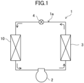
FIG. 1 is a refrigerant circuit diagram showing a configuration of a refrigeration apparatus according to a first embodiment. -
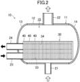
FIG. 2 is a cross-sectional side view showing a configuration of a shell-and-plate heat exchanger. -
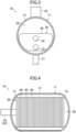
FIG. 3 is a cross-sectional front view showing the configuration of the shell-and-plate heat exchanger. -
FIG. 4 is a cross-sectional plan view showing the configuration of the shell-and-plate heat exchanger. -
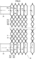
FIG. 5 is a cross-sectional side view showing a configuration of a plate stack. -
FIG. 6 is a cross-sectional side view showing a configuration of a shell-and-plate heat exchanger according to a second embodiment. -
FIG. 7 is a cross-sectional plan view showing the configuration of the shell-and-plate heat exchanger. - As illustrated in
FIG. 1 , a shell-and-plate heat exchanger (10) (will be hereinafter "referred to as a heat exchanger") is provided in a refrigeration apparatus (1). The refrigeration apparatus (1) includes a refrigerant circuit (1a) filled with a refrigerant. The refrigerant circuit (1a) includes a compressor (2), a radiator (3), a decompression mechanism (4), and the heat exchanger (10) serving as an evaporator. The decompression mechanism (4) is, for example, an expansion valve. The refrigerant circuit (1a) performs a vapor compression refrigeration cycle. - The refrigeration apparatus (1) is an air conditioner. The air conditioner may be any of a cooling-only apparatus, a heating-only apparatus, or an air conditioner switchable between cooling and heating. In this case, the air conditioner has a switching mechanism (e.g., a four-way switching valve) configured to switch the direction of circulation of the refrigerant. The refrigeration apparatus (1) may be a water heater, a chiller unit, or a cooling apparatus configured to cool air in an internal space. The cooling apparatus cools the air in an internal space of a refrigerator, a freezer, a container, or the like.
- As illustrated in
FIGS. 2 to 4 , the heat exchanger (10) includes a shell (11) and a plate stack (30). The plate stack (30) is housed in an internal space (15) of the shell (11). - A liquid refrigerant flows into the internal space (15) of the shell (11). The liquid refrigerant exchanges heat with a heating medium flowing in the plate stack (30). As can be seen, the heat exchanger (10) allows the refrigerant that has flowed into the internal space (15) of the shell (11) to evaporate, and thus, functions as an evaporator. Examples of the heating medium used include water and brine.
- The shell (11) includes a cylindrical body (12), a first closing member (13), and a second closing member (14). The cylindrical body (12) is a circular cylindrical member extending in a horizontal direction and having openings on both axial ends.
- The first closing member (13) closes an opening on one end (the left end in
FIG. 2 ) of the cylindrical body (12). The first closing member (13) is attached to the cylindrical body (12) by welding. The first closing member (13) is formed into a curved shape protruding outward in the axial direction of the cylindrical body (12). - The second closing member (14) closes an opening on the other end (the right end in
FIG. 2 ) of the cylindrical body (12). The second closing member (14) is attached to the cylindrical body (12) by welding. The second closing member (14) is formed into a curved shape protruding outward in the axial direction of the cylindrical body (12). - The shell (11) has the internal space (15) defined by the cylindrical body (12), the first closing member (13), and the second closing member (14). The internal space (15) stores therein the liquid refrigerant. The plate stack (30) is housed in the internal space (15). The cylindrical body (12) has an axial length that is shorter than the length of the plate stack (30) in a stacking direction.
- Thus, a left end portion of the plate stack (30) beyond the left end portion of the cylindrical body (12) is arranged in the first closing member (13). A right end portion of the plate stack (30) beyond the right end portion of the cylindrical body (12) is arranged in the second closing member (14).
- As can be seen, the first closing member (13) and the second closing member (14) formed into a curved shape can reduce the deformation caused by the pressure of the refrigerant that has flowed into the internal space (15) of the shell (11) and reduce the weight of the shell (11) as a whole. Arranging part of the plate stack (30) in the first closing member (13) and the second closing member (14) formed into the curved shape can reduce the size of the shell (11) as a whole.
- The cylindrical body (12) is provided with a refrigerant inlet (21) and a refrigerant outlet (22). The refrigerant inlet (21) is formed at the bottom of the cylindrical body (12). The refrigerant is introduced into the internal space (15) through the refrigerant inlet (21).
- The refrigerant outlet (22) is formed at the top of the cylindrical body (12). The refrigerant evaporated in the internal space (15) is emitted out of the shell (11) through the refrigerant outlet (22). The refrigerant inlet (21) and the refrigerant outlet (22) are connected to the refrigerant circuit (1a).
- The first closing member (13) is provided with a heating medium inlet (23) and a heating medium outlet (24). The heating medium inlet (23) and the heating medium outlet (24) are tubular members.
- The heating medium inlet (23) penetrates the first closing member (13). The heating medium inlet (23) is connected to a heating medium introduction path (33) of the plate stack (30). The heating medium inlet (23) supplies the heating medium to the plate stack (30). The refrigerant that has flowed into the internal space (15) of the shell (11) exchanges heat with the heating medium that has flowed into heating medium channels (32), which will be described later, of the plate stack (30).
- The heating medium outlet (24) penetrates the first closing member (13) above the heating medium inlet (23). The heating medium outlet (24) is connected to a heating medium emission path (34) of the plate stack (30). The heating medium outlet (24) emits the heating medium out of the plate stack (30).
- The plate stack (30) includes a plurality of heat transfer plates (40) stacked and joined together. The plate stack (30) is housed in the internal space (15) of the shell (11) in a posture in which the stacking direction of the heat transfer plates (40) is the lateral direction.
- As illustrated in
FIG. 5 , the heat transfer plates (40) include first plates (40a) and second plates (40b). The first plates (40a) and the second plates (40b) are alternately stacked to form the plate stack (30). In the following description, for each of the first plates (40a) and the second plates (40b), a surface on the left side inFIG. 5 will be referred to as a "front surface," and a surface on the right side inFIG. 5 will be referred to as a "back surface." - Each of the first plates (40a) has an inlet protrusion (41a) and an outlet protrusion (43a). The inlet protrusion (41a) and the outlet protrusion (43a) are portions of the first plate (40a) bulged toward the front surface.
- The inlet protrusion (41a) is formed in a lower portion of the first plate (40a). A first inlet hole (42a) is formed in a center portion of the inlet protrusion (41a). The first inlet hole (42a) is a circular hole penetrating the first plate (40a) in a thickness direction.
- The outlet protrusion (43a) is formed in an upper portion of the first plate (40a). A first outlet hole (44a) is formed in a center portion of the outlet protrusion (43a). The first outlet hole (44a) is a circular hole penetrating the first plate (40a) in the thickness direction.
- Each of the second plates (40b) has an inlet recess (41b) and an outlet recess (43b). The inlet recess (41b) and the outlet recess (43b) are portions of the second plate (40b) bulged toward the back surface.
- The inlet recess (41b) is formed in a lower portion of the second plate (40b). A second inlet hole (42b) is formed in a center portion of the inlet recess (41b). The second inlet hole (42b) is a circular hole penetrating the second plate (40b) in the thickness direction. The inlet recess (41b) is positioned to face the inlet protrusion (41a) of the first plate (40a). The second inlet hole (42b) is positioned to face the first inlet hole (42a) of the first plate (40a).
- The outlet recess (43b) is formed in an upper portion of the second plate (40b). A second outlet hole (44b) is formed in a center portion of the outlet recess (43b). The second outlet hole (44b) is a circular hole penetrating the second plate (40b) in the thickness direction. The outlet recess (43b) is positioned to face the outlet protrusion (43a) of the first plate (40a). The second outlet hole (44b) is positioned to face the first outlet hole (44a) of the first plate (40a).
- In the plate stack (30), each first plate (40a) and an adjacent one of the second plates (40b) on the back side of the first plate (40a) are welded together at their peripheral portions along the entire perimeter. These plates may be brazed together.
- In the plate stack (30), the first inlet hole (42a) of each first plate (40a) overlaps the second inlet hole (42b) of an adjacent one of the second plates (40b) on the front side of the first plate (40a). The rims of the overlapping first inlet hole (42a) and second inlet hole (42b) are welded together along the entire perimeter. These rims may be brazed together. The first inlet hole (42a) and the second inlet hole (42b) communicate with the heating medium channels (32), which will be described later, to introduce the heating medium into the heating medium channels (32).
- In the plate stack (30), the first outlet hole (44a) of each first plate (40a) overlaps the second outlet hole (44b) of an adjacent one of the second plates (40b) on the front side of the first plate (40a). The rims of the overlapping first outlet hole (44a) and second outlet hole (44b) are welded together along the entire perimeter. These rims may be brazed together. The first outlet hole (44a) and the second outlet hole (44b) communicate with the heating medium channels (32), which will be described later, to emit the heating medium out of the heating medium channels (32).
- In the plate stack (30), the inlet protrusions (41a) and first inlet holes (42a) of the first plates (40a) and the inlet recesses (41b) and second inlet holes (42b) of the second plates (40b) form the heating medium introduction path (33).
- In the plate stack (30), the outlet protrusions (43a) and first outlet holes (44a) of the first plates (40a) and the outlet recesses (43b) and second outlet holes (44b) of the second plates (40b) form the heating medium emission path (34).
- The heating medium introduction path (33) is a passage extending in the stacking direction of the heat transfer plates (40) in the plate stack (30). The heating medium introduction path (33) is a passage blocked from the internal space (15) of the shell (11), and allows all the heating medium channels (32) to communicate with the heating medium inlet (23).
- The heating medium emission path (34) is a passage extending in the stacking direction of the heat transfer plates (40) in the plate stack (30). The heating medium emission path (34) is a passage blocked from the internal space (15) of the shell (11), and allows all the heating medium channels (32) to communicate with the heating medium outlet (24).
- The plate stack (30) includes a refrigerant channel (31) and a heating medium channel (32). The refrigerant channel (31) and the heating medium channel (32) are formed with a heat transfer plate (40) interposed therebetween, and include a plurality of refrigerant channels (31) and a plurality of heating medium channels (32). The heat transfer plate (40) separates the refrigerant channel (31) and the heating medium channel (32) from each other. Each of the first plate (40a) and the second plate (40b) includes repetition of long and narrow ridges and grooves.
- Each first plate (40a) includes first front-side protrusions (45a) and first back-side protrusions (47a) alternately arranged. The first front-side protrusions (45a) bulge toward the front side of the first plate (40a). The first back-side protrusions (47a) bulge toward the back side of the first plate (40a).
- Each second plate (40b) includes second front-side protrusions (47b) and second back-side protrusions (45b) alternately arranged. The second front-side protrusions (47b) bulge toward the front side of the second plate (40b). The second back-side protrusions (45b) bulge toward the back side of the second plate (40b).
- Each of the refrigerant channels (31) is a channel sandwiched between the front surface of the first plate (40a) and the back surface of the second plate (40b). The refrigerant channel (31) is a channel that communicates with the internal space (15) of the shell (11) and allows the refrigerant to flow therethrough.
- Specifically, each refrigerant channel (31) includes channels formed between the front surfaces of the first back-side protrusions (47a) and the back surfaces of the second front-side protrusions (47b), and spaces formed between the first front-side protrusions (45a) and the second back-side protrusions (45b).
- Each of the heating medium channels (32) is a channel sandwiched between the back surface of the first plate (40a) and the front surface of the second plate (40b). The heating medium channel (32) is a channel blocked from the internal space (15) of the shell (11) and allows the heating medium to flow therethrough.
- Specifically, each heating medium channel (32) includes channels formed between the back surfaces of the first front-side protrusions (45a) and the front surfaces of the second back-side protrusions (45b), and spaces formed between the first back-side protrusions (47a) and the second front-side protrusions (47b).
- Flows of the heating medium and the refrigerant in the heat exchanger (10) will be described. The flow of the heating medium is shown by the arrows in
FIG. 5 . - As illustrated in
FIG. 5 , the heating medium flows from the heating medium inlet (23) into the heating medium introduction path (33). The heating medium flowing through the heating medium introduction path (33) flows from the first inlet holes (42a) and the second inlet holes (42b) toward the first outlet holes (44a) and the second outlet holes (44b) through the heating medium channels (32). - Specifically, the heating medium flowing through the heating medium introduction path (33) enters the heating medium channel (32). The heating medium flows along the heating medium channel (32), passes through the space formed between the first back-side protrusion (47a) and the second front-side protrusion (47b), and enters an adjacent heating medium channel (32) above the heating medium channel (32). In this manner, the heating medium flows upward while flowing from one end to the other of the heat transfer plate (40).
- Next, the flow of the refrigerant will be described below. The refrigerant that has passed through the decompression mechanism (4) in the refrigerant circuit (1a) flows toward the heat exchanger (10). The liquid refrigerant flows into the internal space (15) of the shell (11) through the refrigerant inlet (21). The liquid refrigerant stored in the internal space (15) reaches close to the upper end of the plate stack (30). The plate stack (30) is immersed in the liquid refrigerant. The refrigerant stored in the internal space (15) has a relatively low pressure. The low-pressure refrigerant exchanges heat with the heating medium flowing through the heating medium channels (32).
- Specifically, the refrigerant channel (31) and the heating medium channel (32) are adjacent to each other with the heat transfer plate (40) interposed therebetween. Thus, the liquid refrigerant absorbs heat from the heating medium flowing through the heating medium channel (32) and evaporates. The evaporated refrigerant moves from the refrigerant channel (31) further upward from the plate stack (30). The evaporated refrigerant flows out through the refrigerant outlet (22) into the refrigerant circuit.
- According to a feature of this embodiment, at least one of the first closing member (13) or the second closing member (14) is formed into a curved shape, which makes it possible to reduce deformation caused by the pressure of the refrigerant that has flowed into the internal space (15) of the shell (11) and reduce the weight of the shell (11) as a whole. Arranging part of the plate stack (30) in the at least one of the first closing member (13) or the second closing member (14) formed into the curved shape can reduce the size of the shell (11) as a whole.
- According to a feature of this embodiment, the cylindrical body (12) has an axial length shorter than the length of the plate stack (30) in the stacking direction, which makes it possible to reduce the size of the shell (11) as a whole.
- According to a feature of this embodiment, both of the first closing member (13) and the second closing member (14) are formed into a curved shape, which makes it possible to reduce deformation caused by the pressure of the refrigerant that has flowed into the internal space (15) of the shell (11) and reduce the weight of the shell (11) as a whole.
- According to a feature of this embodiment, the first closing member (13) and the second closing member (14) are attached to the cylindrical body (12) by welding, which makes it possible to increase the strength of the shell (11).
- According to a feature of this embodiment, a refrigeration apparatus includes: the shell-and-plate heat exchanger (10); and the refrigerant circuit (1a) through which the refrigerant to exchange heat in the shell-and-plate heat exchanger (10) flows. It is thus possible to provide a refrigeration apparatus including the shell-and-plate heat exchanger (10).
- In the following description, the same reference characters designate the same components as those of the first embodiment, and the description is focused only on the difference.
- As illustrated in
FIGS. 6 and 7 , a shell (11) includes a cylindrical body (12), a first closing member (13), and a second closing member (14). A plate stack (30) is housed in an internal space (15) of the shell (11). - The shell (11) includes reinforcing members (50). The reinforcing members (50) include first reinforcing members (51) and second reinforcing members (52). The first reinforcing members (51) and the second reinforcing members (52) are configured as plate-shaped members extending in the vertical direction.
- The first reinforcing members (51) are arranged between one end portion (right end portion in
FIG. 6 ) of the plate stack (30) in the stacking direction and the inner wall surface of the first closing member (13) formed into a curved shape. The first reinforcing members (51) are welded to the first closing member (13). The first reinforcing members (51) may be welded to the plate stack (30). - The first reinforcing members (51) support the left end portion of the plate stack (30). The plurality of first reinforcing members (51) are spaced apart from one another in the direction of depth of the sheet of
FIG. 6 (the upward/downward direction inFIG. 7 ). - The second reinforcing members (52) are arranged between the other end portion (right end portion in
FIG. 6 ) of the plate stack (30) in the stacking direction and the inner wall surface of the second closing member (14) formed into a curved shape. The second reinforcing members (52) are welded to the second closing member (14). The second reinforcing members (52) may be welded to the plate stack (30). - The second reinforcing members (52) support the right end portion of the plate stack (30). The plurality of second reinforcing members (52) are spaced apart from one another in the direction of depth of the sheet of
FIG. 6 (the upward/downward direction inFIG. 7 ). - According to a feature of this embodiment, the reinforcing members (50) support the plate stack (30), which makes it possible to increase the strength of the shell-and-plate heat exchanger as a whole.
- According to a feature of this embodiment, the reinforcing members (50) can keep the plate stack (30) from being deformed in the stacking direction.
- According to a feature of this embodiment, a plurality of reinforcing members (50) are provided, which makes it possible to increase the strength of the shell-and-plate heat exchanger as a whole.
- It is not necessary to provide the reinforcing members (50) if the plate stack (30) has sufficiently high strength in the stacking direction, such as in a case in which adjacent heat transfer plates (40) are brazed to each other in the plate stack (30).
- While the embodiments and variations have been described above, it will be understood that various changes in form and details can be made without departing from the spirit and scope of the claims. The elements according to the embodiments, the variations thereof, and the other embodiments may be combined and replaced with each other. In addition, the expressions of "first," "second," "third," ... , in the specification and claims are used to distinguish the terms to which these expressions are given, and do not limit the number and order of the terms.
- As can be seen from the foregoing description, the present disclosure is useful for a shell-and-plate heat exchanger and a refrigeration apparatus.
-
- 1
- Refrigeration Apparatus
- 1a
- Refrigerant Circuit
- 10
- Shell-and-Plate Heat Exchanger
- 11
- Shell
- 12
- Cylindrical Body
- 13
- First Closing Member
- 14
- Second Closing Member
- 15
- Internal Space
- 30
- Plate Stack
- 32
- Heating Medium Channel
- 40
- Heat Transfer Plate
- 50
- Reinforcing Member
Claims (8)
- A shell-and-plate heat exchanger, comprising: a shell (11) having an internal space (15); and a plate stack (30) housed in the internal space (15) and including a plurality of heat transfer plates (40) stacked and joined together, the shell-and-plate heat exchanger causing heat exchange between a refrigerant that has flowed into the internal space (15) of the shell (11) and a heating medium that has flowed into a heating medium channel (32) of the plate stack (30),the shell (11) including: a cylindrical body (12) having openings on both axial ends; a first closing member (13) configured to close the opening on one end of the cylindrical body (12); and a second closing member (14) configured to close the opening on the other end of the cylindrical body (12),at least one of the first closing member (13) or the second closing member (14) being formed into a curved shape protruding outward in an axial direction of the cylindrical body (12),part of the plate stack (30) being arranged in the at least one of the first closing member (13) or the second closing member (14) formed into the curved shape.
- The shell-and-plate heat exchanger of claim 1, wherein
the cylindrical body (12) has an axial length shorter than a length of the plate stack (30) in a stacking direction. - The shell-and-plate heat exchanger of claim 1 or 2, wherein
both of the first closing member (13) and the second closing member (14) are formed into a curved shape protruding outward in the axial direction of the cylindrical body (12). - The shell-and-plate heat exchanger of any one of claims 1 to 3, further comprising:
a reinforcing member (50) arranged between the plate stack (30) and the at least one of the first closing member (13) or the second closing member (14) formed into the curved shape, the reinforcing member (50) being configured to support the plate stack (30). - The shell-and-plate heat exchanger of claim 4, wherein
the reinforcing member (50) is arranged to extend between an end portion of the plate stack (30) in the stacking direction and an inner wall surface of the at least one of the first closing member (13) or the second closing member (14) formed into the curved shape. - The shell-and-plate heat exchanger of claim 5, wherein
the reinforcing member (50) includes a plurality of reinforcing members (50) spaced apart from one another. - The shell-and-plate heat exchanger of any one of claims 1 to 6, wherein
the first closing member (13) and the second closing member (14) are attached to the cylindrical body (12) by welding. - A refrigeration apparatus, comprising:the shell-and-plate heat exchanger (10) of any one of claims 1 to 7; anda refrigerant circuit (1a) through which a refrigerant to exchange heat in the shell-and-plate heat exchanger (10) flows.
Applications Claiming Priority (2)
| Application Number | Priority Date | Filing Date | Title |
|---|---|---|---|
| JP2023053919A JP2024141995A (en) | 2023-03-29 | 2023-03-29 | Shell and plate type heat exchanger and refrigeration device |
| PCT/JP2024/008359 WO2024203042A1 (en) | 2023-03-29 | 2024-03-05 | Shell-and-plate type heat exchanger and refrigeration device |
Publications (2)
| Publication Number | Publication Date |
|---|---|
| EP4464969A1 true EP4464969A1 (en) | 2024-11-20 |
| EP4464969A4 EP4464969A4 (en) | 2025-06-04 |
Family
ID=91967139
Family Applications (1)
| Application Number | Title | Priority Date | Filing Date |
|---|---|---|---|
| EP24734785.9A Pending EP4464969A4 (en) | 2023-03-29 | 2024-03-05 | Shell-and-plate heat exchanger and cooling device |
Country Status (5)
| Country | Link |
|---|---|
| US (1) | US20250369696A1 (en) |
| EP (1) | EP4464969A4 (en) |
| JP (2) | JP2024141995A (en) |
| CN (1) | CN120584267A (en) |
| WO (1) | WO2024203042A1 (en) |
Family Cites Families (7)
| Publication number | Priority date | Publication date | Assignee | Title |
|---|---|---|---|---|
| SE464938B (en) * | 1989-11-02 | 1991-07-01 | Alfa Laval Desalt | PLATFORMERS WHEN THE SEALING ARRANGEMENT PROMOTES THE DISTRIBUTION OF THE VEETSKAN FOR THE PLATE SURFACE AND HEATER-EXHAUSTING STREAMS IN THE LOW PLATES |
| JP2604735Y2 (en) * | 1992-04-09 | 2000-06-05 | 石川島播磨重工業株式会社 | Plate fin heat exchanger |
| SE525354C2 (en) * | 2003-06-18 | 2005-02-08 | Alfa Laval Corp Ab | Heat exchanger device and plate package |
| EP2802835B1 (en) * | 2012-01-12 | 2018-09-05 | Westinghouse Electric Company LLC | Modular plate and shell heat exchanger |
| SI3372938T1 (en) * | 2017-03-10 | 2021-01-29 | Alfa Laval Corporate Ab | Plate package using a heat exchanger plate with integrated draining channel and a heat exchanger including such plate package |
| JP6796906B2 (en) | 2017-06-06 | 2020-12-09 | 株式会社前川製作所 | Refrigerant heat exchanger and secondary refrigerant refrigeration system equipped with this |
| CN211926565U (en) * | 2020-04-13 | 2020-11-13 | 肇庆中彩机电技术研发有限公司 | Condensing heat exchanger |
-
2023
- 2023-03-29 JP JP2023053919A patent/JP2024141995A/en active Pending
-
2024
- 2024-03-05 CN CN202480008789.7A patent/CN120584267A/en active Pending
- 2024-03-05 WO PCT/JP2024/008359 patent/WO2024203042A1/en not_active Ceased
- 2024-03-05 EP EP24734785.9A patent/EP4464969A4/en active Pending
-
2025
- 2025-01-21 JP JP2025008729A patent/JP2025065164A/en active Pending
- 2025-08-14 US US19/300,089 patent/US20250369696A1/en active Pending
Also Published As
| Publication number | Publication date |
|---|---|
| US20250369696A1 (en) | 2025-12-04 |
| EP4464969A4 (en) | 2025-06-04 |
| JP2024141995A (en) | 2024-10-10 |
| JP2025065164A (en) | 2025-04-17 |
| WO2024203042A1 (en) | 2024-10-03 |
| CN120584267A (en) | 2025-09-02 |
Similar Documents
| Publication | Publication Date | Title |
|---|---|---|
| US10371422B2 (en) | Condenser with tube support structure | |
| US10041710B2 (en) | Heat exchanger and air conditioner | |
| JP2018162900A (en) | Heat exchanger and air conditioner including the same | |
| EP3141859B1 (en) | Micro channel type heat exchanger | |
| JP6497262B2 (en) | Laminate heat exchanger | |
| CN114174753A (en) | Heat exchanger and heat pump device | |
| EP3473963A1 (en) | Heat exchanger and air conditioner | |
| KR20220041165A (en) | Heat exchangers and refrigeration cycle units | |
| JP2018091503A (en) | Heat exchanger | |
| JP2011058649A (en) | Heat exchanger and refrigerating machine | |
| US20250369696A1 (en) | Shell-and-plate heat exchanger and refrigeration apparatus | |
| US12305937B2 (en) | Heat exchanger and air-conditioning apparatus employing the same | |
| JPWO2018047299A1 (en) | Plate heat exchanger and refrigeration cycle equipment | |
| EP4741754A1 (en) | Shell and plate heat exchanger and refrigeration device | |
| JP7716575B2 (en) | Heat exchanger and refrigeration cycle device | |
| JP2017219212A (en) | Internal heat exchanger integral type accumulator and freezing cycle using the accumulator | |
| US20250377175A1 (en) | Shell-and-plate heat exchanger and refrigeration apparatus | |
| KR102131158B1 (en) | Air conditioner system for vehicle | |
| JP2022118413A (en) | Heat exchanger | |
| KR102711184B1 (en) | Heat exchanger | |
| JP2026028330A (en) | Shell and plate type heat exchanger and refrigeration equipment | |
| JP4690867B2 (en) | Heat exchanger and air conditioner | |
| JP2025045994A (en) | Heat exchanger and refrigeration cycle device | |
| WO2023195040A1 (en) | Heat exchanger, and outdoor unit for air conditioner | |
| WO2024236763A1 (en) | Heat exchanger, outdoor unit provided with heat exchanger, and air conditioning device provided with outdoor unit |
Legal Events
| Date | Code | Title | Description |
|---|---|---|---|
| STAA | Information on the status of an ep patent application or granted ep patent |
Free format text: STATUS: UNKNOWN |
|
| STAA | Information on the status of an ep patent application or granted ep patent |
Free format text: STATUS: THE INTERNATIONAL PUBLICATION HAS BEEN MADE |
|
| PUAI | Public reference made under article 153(3) epc to a published international application that has entered the european phase |
Free format text: ORIGINAL CODE: 0009012 |
|
| STAA | Information on the status of an ep patent application or granted ep patent |
Free format text: STATUS: REQUEST FOR EXAMINATION WAS MADE |
|
| 17P | Request for examination filed |
Effective date: 20240628 |
|
| AK | Designated contracting states |
Kind code of ref document: A1 Designated state(s): AL AT BE BG CH CY CZ DE DK EE ES FI FR GB GR HR HU IE IS IT LI LT LU LV MC ME MK MT NL NO PL PT RO RS SE SI SK SM TR |
|
| P01 | Opt-out of the competence of the unified patent court (upc) registered |
Free format text: CASE NUMBER: APP_1118/2025 Effective date: 20250108 |
|
| A4 | Supplementary search report drawn up and despatched |
Effective date: 20250507 |
|
| RIC1 | Information provided on ipc code assigned before grant |
Ipc: F28F 9/02 20060101ALI20250429BHEP Ipc: F25B 39/00 20060101ALI20250429BHEP Ipc: F28D 9/00 20060101AFI20250429BHEP |