EP4464916A1 - Machine with hollow portion for electrical wiring - Google Patents
Machine with hollow portion for electrical wiring Download PDFInfo
- Publication number
- EP4464916A1 EP4464916A1 EP22920214.8A EP22920214A EP4464916A1 EP 4464916 A1 EP4464916 A1 EP 4464916A1 EP 22920214 A EP22920214 A EP 22920214A EP 4464916 A1 EP4464916 A1 EP 4464916A1
- Authority
- EP
- European Patent Office
- Prior art keywords
- shaft
- hollow
- electrical wiring
- wiring
- hollow portion
- Prior art date
- Legal status (The legal status is an assumption and is not a legal conclusion. Google has not performed a legal analysis and makes no representation as to the accuracy of the status listed.)
- Pending
Links
Images

Classifications
-
- H—ELECTRICITY
- H02—GENERATION; CONVERSION OR DISTRIBUTION OF ELECTRIC POWER
- H02K—DYNAMO-ELECTRIC MACHINES
- H02K7/00—Arrangements for handling mechanical energy structurally associated with dynamo-electric machines, e.g. structural association with mechanical driving motors or auxiliary dynamo-electric machines
- H02K7/003—Couplings; Details of shafts
-
- H—ELECTRICITY
- H01—ELECTRIC ELEMENTS
- H01R—ELECTRICALLY-CONDUCTIVE CONNECTIONS; STRUCTURAL ASSOCIATIONS OF A PLURALITY OF MUTUALLY-INSULATED ELECTRICAL CONNECTING ELEMENTS; COUPLING DEVICES; CURRENT COLLECTORS
- H01R31/00—Coupling parts supported only by co-operation with counterpart
- H01R31/06—Intermediate parts for linking two coupling parts, e.g. adapter
-
- F—MECHANICAL ENGINEERING; LIGHTING; HEATING; WEAPONS; BLASTING
- F16—ENGINEERING ELEMENTS AND UNITS; GENERAL MEASURES FOR PRODUCING AND MAINTAINING EFFECTIVE FUNCTIONING OF MACHINES OR INSTALLATIONS; THERMAL INSULATION IN GENERAL
- F16H—GEARING
- F16H1/00—Toothed gearings for conveying rotary motion
- F16H1/28—Toothed gearings for conveying rotary motion with gears having orbital motion
- F16H1/32—Toothed gearings for conveying rotary motion with gears having orbital motion in which the central axis of the gearing lies inside the periphery of an orbital gear
-
- H—ELECTRICITY
- H02—GENERATION; CONVERSION OR DISTRIBUTION OF ELECTRIC POWER
- H02K—DYNAMO-ELECTRIC MACHINES
- H02K5/00—Casings; Enclosures; Supports
- H02K5/04—Casings or enclosures characterised by the shape, form or construction thereof
- H02K5/22—Auxiliary parts of casings not covered by groups H02K5/06-H02K5/20, e.g. shaped to form connection boxes or terminal boxes
- H02K5/225—Terminal boxes or connection arrangements
-
- H—ELECTRICITY
- H02—GENERATION; CONVERSION OR DISTRIBUTION OF ELECTRIC POWER
- H02K—DYNAMO-ELECTRIC MACHINES
- H02K7/00—Arrangements for handling mechanical energy structurally associated with dynamo-electric machines, e.g. structural association with mechanical driving motors or auxiliary dynamo-electric machines
- H02K7/10—Structural association with clutches, brakes, gears, pulleys or mechanical starters
- H02K7/116—Structural association with clutches, brakes, gears, pulleys or mechanical starters with gears
-
- H—ELECTRICITY
- H02—GENERATION; CONVERSION OR DISTRIBUTION OF ELECTRIC POWER
- H02K—DYNAMO-ELECTRIC MACHINES
- H02K2203/00—Specific aspects not provided for in the other groups of this subclass relating to the windings
- H02K2203/03—Machines characterised by the wiring boards, i.e. printed circuit boards or similar structures for connecting the winding terminations
Definitions
- the present invention relates to a machine such as a hollow reducer or hollow motor through which electrical wiring is led via a hollow portion extending through a central portion of a machine body in an axial direction.
- Patent Literature 1 discloses a hollow actuator comprising an electric motor and a reducer, each of which is provided with a hollow portion through which electrical wiring can be threaded.
- a cylinder body is press-fitted, in a state allowing rotation, into the inner peripheral surface of a hollow portion in a fixed shaft, and electrical wiring is threaded through the interior of the cylinder body.
- the machine provided with a hollow portion for electrical wiring according to the present invention is characterized by comprising:
- a shaft member provided with electrical wiring and hard-wiring terminals is positioned in a hollow portion.
- the electrical wiring positioned through the hollow portion does not interfere with the ends or other portions of the hollow portion, making it possible to reduce the risk of disconnection. Additionally, there are fewer constraints on the quantity and wire diameter of the wiring than when a requisite quantity of electrical wiring is threaded through the hollow portion. Furthermore, an advantage is presented in that wiring work is simplified.
- FIG. 1 is a schematic longitudinal cross-sectional view showing a hollow strain wave gearing.
- a body component (machine body) of the strain wave gearing 1 is provided with an annular rigid internally toothed gear 2, a top-hat-shaped flexible externally toothed gear 3 positioned coaxially inside the internally toothed gear 2, a wave generator 4 positioned coaxially inside the externally toothed gear 3, a cross roller bearing 5 that supports the internally toothed gear 2 and internally toothed gear 3 in a state allowing relative rotation, and a first end plate 6 and a second end plate 7 that are formed in a disc shape.
- the first and second end plates 6, 7 face each other across a fixed gap along the direction of an axis 1a.
- the internally toothed gear 2, externally toothed gear 3, wave generator 4, and cross roller bearing 5 are positioned between the first and second end plates 6, 7.
- An inner race 51 of the cross roller bearing 5 is securely and coaxially fixed to an outer-peripheral-side section of the first end plate 6 so as to sandwich the internally toothed gear 2 therewith.
- An outer race 52 of the cross roller bearing 5 is securely and coaxially fixed to an outer-peripheral-side section of the second end plate 7 so as to sandwich an annular boss 31 of the internally toothed gear 3 therewith.
- the wave generator 4 positioned inside the externally toothed gear 3 is provided with a hollow input shaft 41, an ellipsoidally contoured plug 42 that is formed integrally with the outer peripheral surface of the hollow input shaft 41, and a wave bearing 43 that is mounted on the ellipsoidal outer peripheral surface of the plug 42.
- a first shaft end portion 41a of the hollow input shaft 41 is rotatably supported on an inner peripheral portion of the first end plate 6 with ball bearings 8 interposed therebetween, and a second shaft end portion 41b on the other side of the hollow input shaft 41 is rotatably supported on an inner peripheral portion of the second end plate 7 with ball bearings 9 interposed therebetween.
- the first shaft end portion 41a of the hollow input shaft 41 protrudes outward from an outer-side end surface 61 of the first end plate 6.
- the second shaft end portion 41b on the other side of the hollow input shaft 41 faces an annular inner-peripheral-side flange 72 formed on the second end plate 7 along the direction of the axis 1a.
- a hollow portion 10 extending through a central portion of the strain wave gearing 1 in the direction of the axis 1a is formed from a hollow portion 41c of the hollow input shaft 41 and a hollow hole 73 defined by a circular inner peripheral surface of the inner-peripheral-side flange 72 of the second end plate 7.
- a first open end 11 on one side of the hollow portion 10 in the direction of the axis 1a is exposed to the outside from the end surface 61 of the first end plate 6, and a second open end 12 on the other side of the hollow portion 10 is exposed to the outside from an end surface 71 of the second end plate 7.
- the externally toothed gear 3 is attached to the second end plate 7, which is a fixed-side member, and the internally toothed gear 2 rotates.
- the rotation of the internally toothed gear 2 is delivered to a load (not shown) via the first end plate 6, to which the internally toothed gear 2 is attached.
- a columnar shaft member 100 for wiring is loosely (rotatably) and coaxially positioned in the hollow portion 10.
- a first shaft end portion 101 on one side of the shaft member 100 in the direction of the axis 1a is exposed from the first open end 11 of the hollow portion 10, and a second shaft end portion 102 on the other side of the shaft member 100 is exposed from the second open end 12 of the hollow portion 10.
- an outer-peripheral-side flange 103 formed in the shape of a large-diameter disc is formed integrally with the second shaft end portion 102, the outer-peripheral-side flange 103 being securely and coaxially fixed to the inner-peripheral-side flange 72 of the second end plate 7.
- a plurality of electrical wiring bundles e.g., two electrical wiring bundles 110, 120, that extend parallel to the axis 1a are positioned inside the shaft member 100 from the first shaft end portion 101 to the second shaft end portion 102.
- the electrical wiring bundles 110, 120 are respectively provided with, e.g., two electrical wirings 111, 112 and two electrical wirings 121, 122.
- the quantity of electrical wiring is not limited to two, and various forms, such as linear or curved, can be employed for arranging the electrical wiring.
- Connectors 131 and 141 which are first hard-wiring terminals, are attached to the end surface of the first shaft end portion 101 of the shaft member 100, and connectors 132 and 142, which are second hard-wiring terminals, are attached to the end surface of the second shaft end portion 102 on the other side of the shaft member 100.
- One wiring end of each of the electrical wirings 111, 112 in the electrical wiring bundle 110 is connected to the connector 131, and the other wiring end of each of the electrical wirings 111, 112 is connected to the connector 132.
- one wiring end of each of the electrical wirings 121, 122 in the electrical wiring bundle 120 is connected to the connector 141, and the other wiring end of each of the electrical wirings 121, 122 is connected to the connector 142.
- Connectors for external electrical wiring can be respectively connected to the connectors 131, 141 on the first-end-plate 6 side, and connectors for external electrical wiring (not shown) can be respectively connected to the connectors 132, 142 on the second-end-plate 7 side.
- the shaft member 100 which is provided with the plurality of electrical wirings and hard-wiring terminals, can be configured as, e.g., an insert-molded component obtained by injection molding using a thermoplastic resin in a state in which the electrical wiring is inserted into a molding mold. Additionally, the shaft member 100 can be configured as a three-dimensionally molded component (MID) obtained using a 3D printer. Furthermore, the shaft member 100 can be configured as a board-incorporating component (board-embedding component) having a configuration in which a printed wiring board or flexible printed wiring board is incorporated (embedded) in the interior. A variety of structures and methods for manufacturing a shaft member provided with electrical wiring can be employed.
- the shaft member 100 which is provided with the plurality of electrical wirings 111, 112, 121, 122 and connectors 131, 132, 141, 142, is positioned in the hollow portion 10 for electrical wiring, which extends through the central portion of the strain wave gearing 1.
- Each of the connectors 131, 141, 132, 142 attached to the first and second shaft end portions 101, 102 on the two sides of the shaft member 100 is exposed to the outside from the end surfaces 61, 71.
- a wiring state identical to that when a requisite quantity of electrical wiring is threaded through the hollow portion 10 is thereby obtained.
- the electrical wirings 111, 112, 121, 122 do not contact the hollow input shaft 41 in which the hollow portion 10 is formed, the end of the second end plate 7, or other such portions, making it possible to reduce the risk of disconnection caused by sliding or twisting. Additionally, it is possible to use an insert-molded component, a three-dimensionally molded component, a board-incorporating component, or the like as the shaft member provided with the electrical wiring, mitigating constraints on the quantity and wire diameter of the wiring over cases where the electrical wiring is threaded directly through the hollow portion 10.
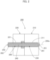
- FIG. 2 is an explanatory drawing showing one example of an actuator to which the present invention is applied.
- a machine body portion of the actuator 200 shown in FIG. 2 is provided with an electric motor 210 and a reducer 220 that are positioned coaxially.
- the electric motor 210 is provided with a hollow rotating shaft 211
- the reducer 220 is provided with a hollow input shaft 221.
- the hollow rotating shaft 211 and the hollow input shaft 221 are coaxially linked, thereby forming a hollow portion 230 extending through the machine body portion in the direction of an axis 200a.
- a shaft member 260 provided with electrical wiring 240 and hard-wiring terminals 251, 252 is loosely (rotatably) and coaxially positioned in the hollow portion 230.
- a first hard-wiring terminal 251 is attached to a first shaft end part 261 of the shaft member 260, the first hard-wiring terminal 251 being exposed from a motor-side open end of the hollow portion 230.
- a second hard-wiring terminal 252 is attached to a second shaft end part 262 of the shaft member 260, the second hard-wiring terminal 252 being exposed from a reducer-side open end of the hollow portion 230.
- the actuator 200 provided with a hollow portion for electrical wiring configured in this manner also exhibits the same effect as in the case of the strain wave gearing 1 shown in FIG. 1 .
Landscapes
- Engineering & Computer Science (AREA)
- Power Engineering (AREA)
- General Engineering & Computer Science (AREA)
- Mechanical Engineering (AREA)
- Connection Of Motors, Electrical Generators, Mechanical Devices, And The Like (AREA)
- Retarders (AREA)
- Manipulator (AREA)
- Motor Or Generator Frames (AREA)
Abstract
Description
- The present invention relates to a machine such as a hollow reducer or hollow motor through which electrical wiring is led via a hollow portion extending through a central portion of a machine body in an axial direction.
- In reducers, electric motors, and other machines, there are cases where a hollow portion extending in an axial direction is formed through a central portion of a machine body in order to thread electrical wiring through the machine body. For example, an input shaft of a reducer and a rotating shaft of an electric motor are configured as hollow shafts, and electrical wiring is led therethrough via hollow portions in the hollow shafts.
Patent Literature 1 discloses a hollow actuator comprising an electric motor and a reducer, each of which is provided with a hollow portion through which electrical wiring can be threaded. Additionally, in the direct drive motor disclosed inPatent Literature 2, a cylinder body is press-fitted, in a state allowing rotation, into the inner peripheral surface of a hollow portion in a fixed shaft, and electrical wiring is threaded through the interior of the cylinder body. -
- Patent Literature 1:
JP 2002-243000 A - Patent Literature 2:
JP 2006-296046 A - When electrical wiring is threaded through a hollow portion formed in a reducer, motor, or other machine, there is a risk of disconnection due to sliding or twisting of the electrical wiring in an open-end portion of the hollow portion. Constraints will also be imposed in regard to the quantity, wire diameter, and other attributes of the wiring being threaded through if the machine has a structure in which the hollow diameter cannot be increased.
- In view of the aforementioned issues, it is an object of the present invention to provide a machine provided with a hollow portion for electrical wiring, configured so that the risk of disconnection can be reduced and constraints on the quantity, wire diameter, and other attributes of wiring can be mitigated.
- In order to solve the aforementioned problem, the machine provided with a hollow portion for electrical wiring according to the present invention is characterized by comprising:
- a machine body;
- a hollow portion extending through a central portion of the machine body in an axial direction;
- a shaft member positioned in the hollow portion;
- a first shaft end portion of the shaft member, the first shaft end portion being exposed at a first open end on one side of the hollow portion;
- a second shaft end portion of the shaft member, the second shaft end portion being exposed at a second open end on the other side of the hollow portion;
- electrical wiring positioned inside the shaft member or integrally molded with the shaft member, the electrical wiring extending from the first shaft end portion to the second shaft end portion;
- a first hard-wiring terminal to which a first wiring end of the electrical wiring is connected, the first hard-wiring terminal being attached to the first shaft end portion of the shaft member; and
- a second hard-wiring terminal to which a second wiring end of the electrical wiring is connected, the second hard-wiring terminal being attached to the second shaft end portion of the shaft member.
- In the present invention, a shaft member provided with electrical wiring and hard-wiring terminals is positioned in a hollow portion. The electrical wiring positioned through the hollow portion does not interfere with the ends or other portions of the hollow portion, making it possible to reduce the risk of disconnection. Additionally, there are fewer constraints on the quantity and wire diameter of the wiring than when a requisite quantity of electrical wiring is threaded through the hollow portion. Furthermore, an advantage is presented in that wiring work is simplified.
-
-
FIG. 1 is a schematic longitudinal cross-sectional view showing one example of a hollow strain wave gearing to which the present invention is applied; and -
FIG. 2 is an explanatory drawing showing one example of an actuator to which the present invention is applied. - Embodiments in which the present invention is applied are described below with reference to the accompanying drawings. The description below illustrates a case where the present invention is applied to a strain wave gearing that is a geared reducer, but the present invention is similarly applicable to reducers other than strain wave gearings, as well as to hollow electric motors, actuators that are provided with electric motors and reducers, and other machines provided with hollow portions for electrical wiring.
-
FIG. 1 is a schematic longitudinal cross-sectional view showing a hollow strain wave gearing. A body component (machine body) of thestrain wave gearing 1 is provided with an annular rigid internallytoothed gear 2, a top-hat-shaped flexible externallytoothed gear 3 positioned coaxially inside the internallytoothed gear 2, a wave generator 4 positioned coaxially inside the externallytoothed gear 3, a cross roller bearing 5 that supports the internallytoothed gear 2 and internallytoothed gear 3 in a state allowing relative rotation, and afirst end plate 6 and asecond end plate 7 that are formed in a disc shape. - The first and
second end plates axis 1a. The internallytoothed gear 2, externallytoothed gear 3, wave generator 4, and cross roller bearing 5 are positioned between the first andsecond end plates inner race 51 of the cross roller bearing 5 is securely and coaxially fixed to an outer-peripheral-side section of thefirst end plate 6 so as to sandwich the internallytoothed gear 2 therewith. Anouter race 52 of the cross roller bearing 5 is securely and coaxially fixed to an outer-peripheral-side section of thesecond end plate 7 so as to sandwich anannular boss 31 of the internallytoothed gear 3 therewith. - The wave generator 4 positioned inside the externally
toothed gear 3 is provided with ahollow input shaft 41, an ellipsoidallycontoured plug 42 that is formed integrally with the outer peripheral surface of thehollow input shaft 41, and a wave bearing 43 that is mounted on the ellipsoidal outer peripheral surface of theplug 42. A firstshaft end portion 41a of thehollow input shaft 41 is rotatably supported on an inner peripheral portion of thefirst end plate 6 withball bearings 8 interposed therebetween, and a secondshaft end portion 41b on the other side of thehollow input shaft 41 is rotatably supported on an inner peripheral portion of thesecond end plate 7 withball bearings 9 interposed therebetween. - The first
shaft end portion 41a of thehollow input shaft 41 protrudes outward from an outer-side end surface 61 of thefirst end plate 6. The secondshaft end portion 41b on the other side of thehollow input shaft 41 faces an annular inner-peripheral-side flange 72 formed on thesecond end plate 7 along the direction of theaxis 1a. A hollow portion 10 extending through a central portion of thestrain wave gearing 1 in the direction of theaxis 1a is formed from ahollow portion 41c of thehollow input shaft 41 and a hollow hole 73 defined by a circular inner peripheral surface of the inner-peripheral-side flange 72 of thesecond end plate 7. A firstopen end 11 on one side of the hollow portion 10 in the direction of theaxis 1a is exposed to the outside from theend surface 61 of thefirst end plate 6, and a secondopen end 12 on the other side of the hollow portion 10 is exposed to the outside from anend surface 71 of thesecond end plate 7. - In the
strain wave gearing 1 configured in this manner, a portion of the externallytoothed gear 3 where external teeth are formed is caused to flex into an ellipsoidal shape by the wave generator 4, andexternal teeth 32 positioned on both ends on a long axis of the ellipsoidal shape mesh withinternal teeth 22 of the internallytoothed gear 2. Rotation is delivered by an electric motor or the like (not shown) to thehollow input shaft 41 of the wave generator 4. When the wave generator 4 rotates, the positions where the externally toothedgear 3 meshes with the internallytoothed gear 2 move in the circumferential direction, and the two gears undergo relative rotation caused by a difference between the numbers of teeth. The externallytoothed gear 3 is attached to thesecond end plate 7, which is a fixed-side member, and the internallytoothed gear 2 rotates. The rotation of the internallytoothed gear 2 is delivered to a load (not shown) via thefirst end plate 6, to which the internallytoothed gear 2 is attached. - A
columnar shaft member 100 for wiring is loosely (rotatably) and coaxially positioned in the hollow portion 10. A firstshaft end portion 101 on one side of theshaft member 100 in the direction of theaxis 1a is exposed from the firstopen end 11 of the hollow portion 10, and a secondshaft end portion 102 on the other side of theshaft member 100 is exposed from the secondopen end 12 of the hollow portion 10. In the present example, an outer-peripheral-side flange 103 formed in the shape of a large-diameter disc is formed integrally with the secondshaft end portion 102, the outer-peripheral-side flange 103 being securely and coaxially fixed to the inner-peripheral-side flange 72 of thesecond end plate 7. - A plurality of electrical wiring bundles, e.g., two
electrical wiring bundles axis 1a are positioned inside theshaft member 100 from the firstshaft end portion 101 to the secondshaft end portion 102. Theelectrical wiring bundles electrical wirings electrical wirings -
Connectors shaft end portion 101 of theshaft member 100, andconnectors shaft end portion 102 on the other side of theshaft member 100. One wiring end of each of theelectrical wirings electrical wiring bundle 110 is connected to theconnector 131, and the other wiring end of each of theelectrical wirings connector 132. Similarly, one wiring end of each of theelectrical wirings electrical wiring bundle 120 is connected to theconnector 141, and the other wiring end of each of theelectrical wirings connector 142. Connectors for external electrical wiring (not shown) can be respectively connected to theconnectors plate 6 side, and connectors for external electrical wiring (not shown) can be respectively connected to theconnectors plate 7 side. As shall be apparent, it is also permissible to position a terminal block in lieu of theconnectors - The
shaft member 100, which is provided with the plurality of electrical wirings and hard-wiring terminals, can be configured as, e.g., an insert-molded component obtained by injection molding using a thermoplastic resin in a state in which the electrical wiring is inserted into a molding mold. Additionally, theshaft member 100 can be configured as a three-dimensionally molded component (MID) obtained using a 3D printer. Furthermore, theshaft member 100 can be configured as a board-incorporating component (board-embedding component) having a configuration in which a printed wiring board or flexible printed wiring board is incorporated (embedded) in the interior. A variety of structures and methods for manufacturing a shaft member provided with electrical wiring can be employed. - In the strain wave gearing 1 in the present example configured as described above, the
shaft member 100, which is provided with the plurality ofelectrical wirings connectors strain wave gearing 1. Each of theconnectors shaft end portions shaft member 100 is exposed to the outside from the end surfaces 61, 71. When performing wiring work, it is permissible to merely connect external wiring or the like to the terminals of theconnectors - The
electrical wirings hollow input shaft 41 in which the hollow portion 10 is formed, the end of thesecond end plate 7, or other such portions, making it possible to reduce the risk of disconnection caused by sliding or twisting. Additionally, it is possible to use an insert-molded component, a three-dimensionally molded component, a board-incorporating component, or the like as the shaft member provided with the electrical wiring, mitigating constraints on the quantity and wire diameter of the wiring over cases where the electrical wiring is threaded directly through the hollow portion 10. Furthermore, the need for work to lead the requisite quantity of electrical wiring from one shaft end of the hollow shaft through the hollow portion out from the other end of the hollow shaft is obviated, and work to connect the electrical wiring that has been threaded through the hollow portion to external wiring or the like is simplified. -
FIG. 2 is an explanatory drawing showing one example of an actuator to which the present invention is applied. A machine body portion of theactuator 200 shown inFIG. 2 is provided with anelectric motor 210 and areducer 220 that are positioned coaxially. Theelectric motor 210 is provided with a hollowrotating shaft 211, and thereducer 220 is provided with ahollow input shaft 221. The hollowrotating shaft 211 and thehollow input shaft 221 are coaxially linked, thereby forming ahollow portion 230 extending through the machine body portion in the direction of anaxis 200a. Ashaft member 260 provided withelectrical wiring 240 and hard-wiringterminals hollow portion 230. - A first hard-
wiring terminal 251 is attached to a firstshaft end part 261 of theshaft member 260, the first hard-wiring terminal 251 being exposed from a motor-side open end of thehollow portion 230. Similarly, a second hard-wiring terminal 252 is attached to a secondshaft end part 262 of theshaft member 260, the second hard-wiring terminal 252 being exposed from a reducer-side open end of thehollow portion 230. - The
actuator 200 provided with a hollow portion for electrical wiring configured in this manner also exhibits the same effect as in the case of the strain wave gearing 1 shown inFIG. 1 .
Claims (6)
- A machine provided with a hollow portion for electrical wiring, comprising:a machine body;the hollow portion extending through a central portion of the machine body in an axial direction;a shaft member positioned in the hollow portion;a first shaft end portion of the shaft member, the first shaft end portion being exposed at a first open end on one side of the hollow portion;a second shaft end portion of the shaft member, the second shaft end portion being exposed at a second open end on the other side of the hollow portion;electrical wiring positioned inside the shaft member or integrally molded with the shaft member, the electrical wiring extending from the first shaft end portion to the second shaft end portion;a first hard-wiring terminal to which a first wiring end of the electrical wiring is connected, the first hard-wiring terminal being attached to the first shaft end portion of the shaft member; anda second hard-wiring terminal to which a second wiring end of the electrical wiring is connected, the second hard-wiring terminal being attached to the second shaft end portion of the shaft member.
- The machine provided with the hollow portion for electrical wiring according to claim 1, further comprising:a hollow shaft provided with the hollow portion;the hollow shaft extending through the central portion of the machine body in the axial direction, a first shaft end portion on one side of the hollow shaft being exposed from the first open end of the hollow portion, and a second shaft end portion on the other side of the hollow shaft being exposed from the second open end of the hollow portion.
- The machine provided with the hollow portion for electrical wiring according to claim 2, whereinthe shaft member isan insert-molded circuit component with which the electrical wiring is integrated through insert molding,a three-dimensionally molded circuit component with which the electrical wiring is integrally molded, ora board-incorporating component in which is incorporated a printed wiring board on which the electrical wiring is printed.
- The machine provided with the hollow portion for electrical wiring according to claim 2, whereinthe machine body is provided with a reducer,the hollow shaft is an input shaft for the reducer,the shaft member extends loosely or rotatably through the hollow portion of the input shaft, andthe first shaft end portion or second shaft end portion of the shaft member is attached to a fixed-side member of the reducer.
- The machine provided with the hollow portion for electrical wiring according to claim 2, whereinthe machine body is provided with an electric motor,the hollow shaft is a rotating shaft of the electric motor,the shaft member extends loosely or rotatably through the hollow portion of the rotating shaft, andthe first shaft end portion or second shaft end portion of the shaft member is attached to a fixed-side member of the electric motor.
- The machine provided with the hollow portion for electrical wiring according to claim 2, wherein:the machine body is provided with an actuator provided with an electric motor and a reducer that are positioned coaxially;the hollow shaft is provided with a rotating shaft of the electric motor and an input shaft of the reducer, the input shaft being coaxially linked to the rotating shaft;the shaft member extends loosely or rotatably through the respective hollow portions of the rotating shaft and the input shaft; andthe first shaft end portion or second shaft end portion of the shaft member is attached to a fixed-side member of the actuator.
Applications Claiming Priority (1)
| Application Number | Priority Date | Filing Date | Title |
|---|---|---|---|
| PCT/JP2022/000775 WO2023135688A1 (en) | 2022-01-12 | 2022-01-12 | Machine with hollow portion for electrical wiring |
Publications (2)
| Publication Number | Publication Date |
|---|---|
| EP4464916A1 true EP4464916A1 (en) | 2024-11-20 |
| EP4464916A4 EP4464916A4 (en) | 2025-11-12 |
Family
ID=87278629
Family Applications (1)
| Application Number | Title | Priority Date | Filing Date |
|---|---|---|---|
| EP22920214.8A Pending EP4464916A4 (en) | 2022-01-12 | 2022-01-12 | MACHINE WITH HOLLOW SECTION FOR ELECTRICAL WIRING |
Country Status (7)
| Country | Link |
|---|---|
| US (1) | US20250015549A1 (en) |
| EP (1) | EP4464916A4 (en) |
| JP (1) | JPWO2023135688A1 (en) |
| KR (1) | KR20240110025A (en) |
| CN (1) | CN118451633A (en) |
| TW (1) | TW202328578A (en) |
| WO (1) | WO2023135688A1 (en) |
Family Cites Families (17)
| Publication number | Priority date | Publication date | Assignee | Title |
|---|---|---|---|---|
| JPH08276392A (en) * | 1995-04-06 | 1996-10-22 | Mitsubishi Electric Corp | Robot equipment |
| JPH10312869A (en) * | 1997-05-14 | 1998-11-24 | Omron Corp | Relay connector |
| JP4510307B2 (en) * | 2001-02-15 | 2010-07-21 | パナソニック株式会社 | Electronic component mounting machine |
| JP2002243000A (en) | 2001-02-19 | 2002-08-28 | Harmonic Drive Syst Ind Co Ltd | Actuator with wave gear reducer |
| JP4676233B2 (en) | 2005-04-07 | 2011-04-27 | シーケーディ株式会社 | Rotary table device |
| JP4997121B2 (en) * | 2008-01-10 | 2012-08-08 | 株式会社ミツバ | Electric rotary joint |
| JP2009273292A (en) * | 2008-05-09 | 2009-11-19 | Mitsuba Corp | Brushless motor |
| WO2010010598A1 (en) * | 2008-07-23 | 2010-01-28 | 株式会社ハーモニック・ドライブ・システムズ | Electric wiring structure of hollow rotator |
| JP6079062B2 (en) * | 2012-08-30 | 2017-02-15 | 株式会社Ihi | Rotating machine |
| KR102061693B1 (en) * | 2013-10-07 | 2020-01-02 | 삼성전자주식회사 | Actuator unit, robot comprising the same and reducing apparatus |
| JP6401034B2 (en) * | 2014-12-02 | 2018-10-03 | 株式会社ミツバ | Hollow motor |
| JP6765193B2 (en) * | 2016-01-27 | 2020-10-07 | Ntn株式会社 | Electric actuator |
| JP2020028136A (en) * | 2018-08-09 | 2020-02-20 | Ntn株式会社 | Vehicle motor drive device |
| EP3690281B1 (en) * | 2018-09-20 | 2022-03-09 | Harmonic Drive Systems Inc. | Unit type wave gear device |
| KR102177405B1 (en) * | 2019-06-07 | 2020-11-12 | 하이젠모터 주식회사 | Driving modules with hollowness |
| JP7643276B2 (en) * | 2021-09-28 | 2025-03-11 | セイコーエプソン株式会社 | Drive unit and robot |
| JP7772815B2 (en) * | 2021-11-05 | 2025-11-18 | ファナック株式会社 | Rotating shaft structure and machinery |
-
2022
- 2022-01-12 CN CN202280084269.5A patent/CN118451633A/en active Pending
- 2022-01-12 US US18/713,406 patent/US20250015549A1/en active Pending
- 2022-01-12 EP EP22920214.8A patent/EP4464916A4/en active Pending
- 2022-01-12 JP JP2023573700A patent/JPWO2023135688A1/ja active Pending
- 2022-01-12 WO PCT/JP2022/000775 patent/WO2023135688A1/en not_active Ceased
- 2022-01-12 KR KR1020247019390A patent/KR20240110025A/en not_active Ceased
- 2022-09-26 TW TW111136294A patent/TW202328578A/en unknown
Also Published As
| Publication number | Publication date |
|---|---|
| CN118451633A (en) | 2024-08-06 |
| KR20240110025A (en) | 2024-07-12 |
| TW202328578A (en) | 2023-07-16 |
| JPWO2023135688A1 (en) | 2023-07-20 |
| US20250015549A1 (en) | 2025-01-09 |
| WO2023135688A1 (en) | 2023-07-20 |
| EP4464916A4 (en) | 2025-11-12 |
Similar Documents
| Publication | Publication Date | Title |
|---|---|---|
| EP3826151A1 (en) | Planetary reduction electrical machine capable of achieving full closed-loop control and articulated robot | |
| JP5084909B2 (en) | Electrical wiring structure for hollow rotating device | |
| JP5540981B2 (en) | Articulated robot | |
| KR101423218B1 (en) | Wave gear device and flexible internally toothed gear | |
| KR20100000342A (en) | Harmonic drive using profile shifted gear | |
| KR102123935B1 (en) | robot | |
| EP3181430B1 (en) | Steering assistance device | |
| US20250015549A1 (en) | Machine with hollow portion for electrical wiring | |
| US20190224895A1 (en) | Gear, gear transmission mechanism and manufacturing method of gear | |
| JP2017005839A (en) | Gear box with motor | |
| JP2866249B2 (en) | Speed reducer series with internal meshing planetary gear structure | |
| KR20210114450A (en) | actuator device | |
| KR20210113341A (en) | small actuator unit | |
| JP2008019902A (en) | Linear motion actuator | |
| WO2006118022A1 (en) | Motor shaft for micromotor, and micromotor | |
| JP6632430B2 (en) | Robot deceleration transmission | |
| WO2023042331A1 (en) | Strain wave gear device | |
| CN216180509U (en) | Anti-twisting actuator, mechanical arm and robot | |
| JP7668548B2 (en) | Harmonic Drive Actuator Gearhead | |
| CN214429403U (en) | a linear actuator | |
| CN118646198A (en) | Rotating device | |
| CN106286716B (en) | Power transmission using inscribed cam and cylindrical pinion | |
| KR102456349B1 (en) | Electronic power steering using planetary gear | |
| JP4630297B2 (en) | Gear device and actuator for printing press having the same | |
| CN100394069C (en) | Orthogonal Power Transfer Device |
Legal Events
| Date | Code | Title | Description |
|---|---|---|---|
| STAA | Information on the status of an ep patent application or granted ep patent |
Free format text: STATUS: THE INTERNATIONAL PUBLICATION HAS BEEN MADE |
|
| PUAI | Public reference made under article 153(3) epc to a published international application that has entered the european phase |
Free format text: ORIGINAL CODE: 0009012 |
|
| STAA | Information on the status of an ep patent application or granted ep patent |
Free format text: STATUS: REQUEST FOR EXAMINATION WAS MADE |
|
| 17P | Request for examination filed |
Effective date: 20240524 |
|
| AK | Designated contracting states |
Kind code of ref document: A1 Designated state(s): AL AT BE BG CH CY CZ DE DK EE ES FI FR GB GR HR HU IE IS IT LI LT LU LV MC MK MT NL NO PL PT RO RS SE SI SK SM TR |
|
| DAV | Request for validation of the european patent (deleted) | ||
| DAX | Request for extension of the european patent (deleted) | ||
| REG | Reference to a national code |
Ref country code: DE Ref legal event code: R079 Free format text: PREVIOUS MAIN CLASS: F16H0001320000 Ipc: H02K0007116000 |
|
| A4 | Supplementary search report drawn up and despatched |
Effective date: 20251013 |
|
| RIC1 | Information provided on ipc code assigned before grant |
Ipc: H02K 7/116 20060101AFI20251007BHEP Ipc: H02K 7/00 20060101ALI20251007BHEP Ipc: F16H 1/32 20060101ALI20251007BHEP |