EP4464628A1 - Sorting device - Google Patents
Sorting device Download PDFInfo
- Publication number
- EP4464628A1 EP4464628A1 EP24169770.5A EP24169770A EP4464628A1 EP 4464628 A1 EP4464628 A1 EP 4464628A1 EP 24169770 A EP24169770 A EP 24169770A EP 4464628 A1 EP4464628 A1 EP 4464628A1
- Authority
- EP
- European Patent Office
- Prior art keywords
- sliding support
- structural subassembly
- actuator
- support surface
- sorting device
- Prior art date
- Legal status (The legal status is an assumption and is not a legal conclusion. Google has not performed a legal analysis and makes no representation as to the accuracy of the status listed.)
- Pending
Links
Images










Classifications
-
- B—PERFORMING OPERATIONS; TRANSPORTING
- B65—CONVEYING; PACKING; STORING; HANDLING THIN OR FILAMENTARY MATERIAL
- B65G—TRANSPORT OR STORAGE DEVICES, e.g. CONVEYORS FOR LOADING OR TIPPING, SHOP CONVEYOR SYSTEMS OR PNEUMATIC TUBE CONVEYORS
- B65G15/00—Conveyors having endless load-conveying surfaces, i.e. belts and like continuous members, to which tractive effort is transmitted by means other than endless driving elements of similar configuration
- B65G15/60—Arrangements for supporting or guiding belts, e.g. by fluid jets
- B65G15/62—Guides for sliding belts
-
- B—PERFORMING OPERATIONS; TRANSPORTING
- B07—SEPARATING SOLIDS FROM SOLIDS; SORTING
- B07C—POSTAL SORTING; SORTING INDIVIDUAL ARTICLES, OR BULK MATERIAL FIT TO BE SORTED PIECE-MEAL, e.g. BY PICKING
- B07C5/00—Sorting according to a characteristic or feature of the articles or material being sorted, e.g. by control effected by devices which detect or measure such characteristic or feature; Sorting by manually actuated devices, e.g. switches
- B07C5/36—Sorting apparatus characterised by the means used for distribution
- B07C5/361—Processing or control devices therefor, e.g. escort memory
- B07C5/362—Separating or distributor mechanisms
-
- B—PERFORMING OPERATIONS; TRANSPORTING
- B65—CONVEYING; PACKING; STORING; HANDLING THIN OR FILAMENTARY MATERIAL
- B65G—TRANSPORT OR STORAGE DEVICES, e.g. CONVEYORS FOR LOADING OR TIPPING, SHOP CONVEYOR SYSTEMS OR PNEUMATIC TUBE CONVEYORS
- B65G21/00—Supporting or protective framework or housings for endless load-carriers or traction elements of belt or chain conveyors
- B65G21/10—Supporting or protective framework or housings for endless load-carriers or traction elements of belt or chain conveyors movable, or having interchangeable or relatively movable parts; Devices for moving framework or parts thereof
- B65G21/14—Supporting or protective framework or housings for endless load-carriers or traction elements of belt or chain conveyors movable, or having interchangeable or relatively movable parts; Devices for moving framework or parts thereof to allow adjustment of length or configuration of load-carrier or traction element
-
- B—PERFORMING OPERATIONS; TRANSPORTING
- B65—CONVEYING; PACKING; STORING; HANDLING THIN OR FILAMENTARY MATERIAL
- B65G—TRANSPORT OR STORAGE DEVICES, e.g. CONVEYORS FOR LOADING OR TIPPING, SHOP CONVEYOR SYSTEMS OR PNEUMATIC TUBE CONVEYORS
- B65G47/00—Article or material-handling devices associated with conveyors; Methods employing such devices
- B65G47/22—Devices influencing the relative position or the attitude of articles during transit by conveyors
- B65G47/26—Devices influencing the relative position or the attitude of articles during transit by conveyors arranging the articles, e.g. varying spacing between individual articles
- B65G47/28—Devices influencing the relative position or the attitude of articles during transit by conveyors arranging the articles, e.g. varying spacing between individual articles during transit by a single conveyor
-
- B—PERFORMING OPERATIONS; TRANSPORTING
- B65—CONVEYING; PACKING; STORING; HANDLING THIN OR FILAMENTARY MATERIAL
- B65G—TRANSPORT OR STORAGE DEVICES, e.g. CONVEYORS FOR LOADING OR TIPPING, SHOP CONVEYOR SYSTEMS OR PNEUMATIC TUBE CONVEYORS
- B65G2203/00—Indexing code relating to control or detection of the articles or the load carriers during conveying
- B65G2203/02—Control or detection
Definitions
- sorting devices are known. It may be desirable to periodically washdown such sorting devices, particularly when used for product or applications where hygiene is especially important, such as but not limited to where the sorting device is interacting with foodstuffs (e.g., poultry by way of non-limiting example). Adequate washdown, drying, and/or other cleaning can be difficult where small gaps are provided, fasteners are utilized, or other small cracks and crevices exist, which may trap water and/or particulate, which may permit microbial growth. This may be particularly important in areas where product may be encountered. Regardless, such devices may require periodic maintenance. Reducing part count and improving removability and reassembly of parts may improve maintenance efforts. This may also reduce the potential for part failure or dislodgement. Therefore, what is needed is a sorting device which addresses these, and other, concerns.
- foodstuffs e.g., poultry by way of non-limiting example.
- Adequate washdown, drying, and/or other cleaning can be difficult where small gaps are provided, fast
- a sorting device and related systems and methods are disclosed which address these, and other, shortcomings in the art.
- the disclosed sorting device and related systems and methods minimize the use of fasteners and small cracks and crevices, particularly in areas where objects are normally encountered.
- the disclosed sorting device and related systems and methods provide ease of component removal and replacement.
- the disclosed sorting device and related systems and methods provide several components which are capable of being attached and operated in various orientations.
- the disclosed sorting devices and related systems and methods may include reciprocating sliding support surfaces which operate to retract and extend conveyor belts while maintaining adequate belt tension.
- a pivoting mechanism may be provided which facilitates the reciprocating movement of upper and lower ones of the sliding support surfaces.
- the pivoting mechanisms may be selectively driven by an actuator located outside an area of travel for the conveyor belt, which may minimize areas where pieces of handled objects may become lodged.
- the actuator is connected, by way of an arm and/or a pivoting device, to an axel which is rotated with movement of the actuator.
- the axel may support multiple members, which extend therefrom to engage, such as by way of posts extending between the members, the sliding support surfaces. Upper ends of the members and/or the posts may be received within apertures at the upper and lower sliding support surfaces.
- Multiple sets of upper and lower sliding support surfaces, pivoting mechanisms, actuators, conveyor belts, and the like may be provided at a given sorting device to provide multiple, independently operable, lanes for product sorting.
- Each of the actuators may be connected to the respective linkage by a respective pivoting member and/or linkage arm, though such is not necessarily required. This may allow selective separation of a first, operable end of the actuator and/or various mechanical advantages or disadvantages.
- a second end of the actuator may be connected to a structural subassembly by way of a plate, which is configured for rotational movement about a pivot. Rotation of the plate may be accomplished by manual operation of a spring plunger to disengage the plunger from the structural subassembly and permit manual rotation of the plate, and the connected actuator, rearward.
- This rearward movement of the actuator may cause further rotation of the axel (e.g., by way of the arm and/or pivoting device) and movement of the pivoting device out of engagement with the sliding support surfaces.
- the actuators may be connected to the plates by way of one or more pins for easy removal.
- the sliding support surfaces may comprise channels which engage protrusions at the structural subassembly and limit travel of the sliding support surfaces to substantially parallel, horizontal movement.
- Rollers may be provided within channels of the structural subassembly to permit easy movement for slackening and removing the conveyor belts, such as for separate washing or other cleaning. Disengagement of the pivoting mechanisms from the sliding support surfaces may permit removal of the sliding support surfaces, such as along the protrusions, from the structural subassembly, such as for separate washing or other cleaning.
- a normally stationary support surface may likewise be mounted and removed, such as by way of additional protrusions on the structural subassembly.
- the disclosed sorting devices and related systems and methods may permit tool-less, rapid removal and replacement of at least the sliding support surfaces, normally stationary support surfaces as well as the pivoting mechanisms, actuators, and/or other components of the sorting devices.
- a drive subassembly may comprise a shaft with spacers for maintaining spacing of sprockets along the shaft.
- the spacers may comprise brackets with apertures sized for the shaft and a member connecting the brackets. This provides a relatively open design over known solutions, such as snap rings and collars, thereby providing relatively easy cleaning and minimizing spaces for microbes or other material to be harbored.
- the spacers may also reduce the potential for failure or dislodgement of such components within a travel path area of the conveyor.
- the disclosed sorting devices and related systems and methods may require fewer parts.
- the sorting devices may contain no bolts, nuts, washers, or actuators at least within a zone interior to the conveyor belt.
- the sorting devices may comprise parts which are orientation independent such that they may be inserted and/or attached in multiple orientations.
- the sorting devices may have moving parts with relatively low weight to lower inertia for quick activation and reactivation time.
- a further one of such a sorting device may comprising a structural subassembly; a conveyor belt located at a first side of a first portion of the structural subassembly, a portion of a travel path for the conveyor belt oriented to accommodate objects for sorting; a drive subassembly engaging the conveyor belt; rollers engaging the conveyor belt; upper and lower sliding support surfaces located at the first side of the first portion of the structural subassembly and at least partially supporting the conveyor belt; a pivoting mechanism located at the first side of the first portion of the structural subassembly, said pivoting mechanism comprising an axel and members extending from the axel to the upper and lower sliding support surfaces; and an actuator located at a second side of the first portion of the structural subassembly, said actuator mechanically linked to the pivoting mechanism such that, when said actuator is operated, the pivoting mechanism pivots, resulting in reciprocating movement of the upper and lower sliding support surfaces to change a length of the portion of the travel path of the conveyor belt
- the drive subassembly may comprise a shaft, a motor for rotating the shaft, belt engagement components located along the shaft and engaging the conveyor belt, and spacers located along the shaft between the belt engagement components.
- the actuator comprises a pneumatic piston; and the actuator is mechanically linked to the axel by way of a lever arm and a pivoting member.
- the actuator is connected to said structural subassembly in a manner which permits spatial translation of the actuator to cause further rotation of the axel and disengagement of the pivoting mechanism from the upper and lower sliding support surfaces.
- Another one of such a sorting device may comprising a structural subassembly; a support structure for the structural subassembly; a conveyor belt having a travel path, an upper portion of said travel path oriented to accommodate goods to be sorted; a drive subassembly engaging the conveyor belt; rollers engaging the conveyor belt, said rollers disposed within channels provided at the structural subassembly which permit manual movement of the rollers; upper and lower sliding support surfaces at least partially supporting the conveyor belt, wherein the upper sliding support surface at least partially defines the upper portion of said travel path; a normally stationary support surface at least partially defining the upper portion of said travel path; a pivoting mechanism provided within an area defined by the travel path of the conveyor belt, said pivoting mechanism comprising an axel and members extending from the axel to the upper and lower sliding support surfaces; a controller; an actuator located outside of the area defined by the travel path of the conveyor belt, electronically connected to the controller, and mechanically connected to the pivoting mechanism by at least a crank arm and
- Embodiments of the invention are described herein with reference to illustrations of idealized embodiments (and intermediate structures) of the invention. As such, variations from the shapes of the illustrations as a result, for example, of manufacturing techniques and/or tolerances, are to be expected. Thus, embodiments of the invention should not be construed as limited to the particular shapes of regions illustrated herein but are to include deviations in shapes that result, for example, from manufacturing.
- FIGURE 1 through FIGURE 3 illustrate exemplary known sorting devices 10.
- a conveyor belt 18 is extended about a number of rollers 16A-16D and a driver 20, which is motorized and comprise sprockets for driving the belt 18.
- An upper support platform 12 comprises a number of members configured for relative sliding movement to shorten an overall upper length of a travel path for the conveyor belt 18 and cause items to be dropped onto a rejection chute 22.
- an actuator 14 is operated to adjust a spatial position of at least one of the rollers 16C.
- the actuator is mounted internal to a travel path of the belt 18. A large number of fasteners are used to create the upper support platform 12.
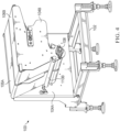
- FIGURE 4 and FIGURE 5 illustrate a sorting device 100 in accordance with the present invention.
- the sorting device 100 may comprise, or be attachable to, a support structure 102, though such is not required.
- the support structure 102 may comprise one or more members, one or more adjustable legs, one or more platforms, one or more members, plates, housings, combinations thereof, or the like.
- the support structure 102 may be configured for mounting or connection to other structures, though such is not required.
- the sorting device 100 may comprise a structural subassembly 104.
- the structural subassembly 104 may comprise one or more panels, plates, members, combinations thereof, or the like.
- the structural subassembly 104 may comprise a first portion 104A and a second portion 104B.
- the first and second portions 104A, 104B may comprise panels which, when considered in combination with conveyor belt(s) 106, entirely or substantially (e.g., ⁇ 75%) enclose an area defined by a travel path of the conveyor belt(s) 106 of the device 100.
- the structural subassembly 104 may comprise any number, size, and/or shape portions.
- Various components of the device 100 may be connected to the structural subassembly 104, in exemplary embodiments, such as at the first portion 104A.
- the second portion 104B may, for example, enclose an area device by conveyor belt(s) 106.
- Additional portions 104C may extend within and/or outside of the area defined by the travel path of conveyor belt(s) 106 of the device 100, such as to extend between and/or divide multiple belts 106, thereby defining lanes for objects to be sorted by the device 100.
- the sorting device 100 may comprise one or multiple belts 106, though such is not required.
- a drive subassembly 108 may be provided which engages, supports, directs, and/or drives the belt(s) 106.
- Each of the belt(s) 106 may be further supported, engaged, and/or directed by one or more rollers 110.
- the drive subassembly 108 may extend between, and/or be supported by, the first and second structural subassembly portions 104A, 104B.
- the drive subassembly 108 and/or the rollers 110 may be common to all belts 106 for a given device 100, though such is not required.
- the drive subassembly 108 and/or the rollers 110 may direct and define a travel path for the belt(s) 106.
- the rollers 110 may comprise posts which are stationary and engage and/or direct the belt(s) 106.
- the posts may be employed to maintain the belt(s) 106 adjacent to the drive subassembly 108, such as to assist with frictional engagement.
- the sorting device may comprise one or more normally stationary support surfaces 105.
- the normally stationary support surfaces 105 may support, engage, and/or direct the belt(s) 106.
- the normally stationary support surfaces 105 may comprise rollers, though such is not required.
- the normally stationary support surfaces 105 may extend between, and/or be supported by, the first and second structural subassembly portions 104A, 104B.
- the normally stationary support surfaces 105 may provide support for objects traveling along the conveyor belt(s) 106.
- At least the normally stationary support surfaces 105, rollers 110, and/or belt(s) 106 may be easily removed and/or reinserted to the structural subassembly 104 of the device 100, such as for washdown or other cleaning, inspection, and/or replacement.
- a portion of the travel path of the belt(s) 106 may be configured to accommodate goods for sorting.
- the upper portion of the travel path of the belt(s) 106 may be relatively flat, extend substantially parallel to a ground surface, and/or be sufficiently oriented to maintain frictional engagement with, and convey, goods under gravitational forces, though such is not required.
- a remaining portion of the travel path of the belt(s) 106 may be sinuous and/or not oriented to maintain frictional engagement with, and convey, goods under gravitational forces when the device 100 is properly oriented.
- any shape or configuration of the travel path may be utilized.
- the upper portion, or other product supporting portion, of the travel path of the belt(s) 106 may be supported by at least the normally stationary support surfaces 105 and an upper one or ones of the sliding support surfaces 116A, which may serve to support the belt(s) 106 and/or the objects to be sorted.
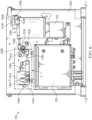
- the device 100 may comprise one or more actuators 134.
- the actuator(s) 134 are provided at a given side of the structural subassembly 104 and/or outside of the area defined by the travel path of the belt(s) 106.
- the actuator(s) 134 are provided at a first side of a first structural subassembly portion 104A. In this way, the actuators 134 may be located outside the area defined by the travel path of the belt(s) 106 and/or may be at least partially shielded from the objects being sorted. This arrangement may also eliminate a need to string air or other lines through the area defined by the travel path of the belt(s) 106.
- the actuators 134 may each be attached to a respective axel 122.
- a first, operable end of the actuators 134 are each attached to the respective axel 122 by way of a linkage 151.
- the linkage 151 may be an arm, such as a crank and/or lever arm.
- the linkage 151 may be connected to the actuator by way of a pivoting member 143.
- the pivoting member 143 may be pivotably connected to the linkage 151.
- the pivoting member 143 may comprise a generally cuboid shape portion having a recess configured to receive the first end of the actuators 134. However, any size and/or shape may be utilized.
- the pivoting member 143 may be mechanically separated from the actuator 134, though such is not required. In other exemplary embodiments, without limitation, the pivoting member 143 is permanently connected to the actuator 134.
- the actuator 134 may be connected to the structural subassembly 104 by way of a bracket portion 141, though such is not required.
- an actuator 134, axel 122 and related components e.g., linkage 151, pivoting member 143 and provided for each belt 106 of the device 100 such that each belt 106 is independently operable.
- a single axel 122, actuator 134, and related components could be utilized to control multiple belts 106.
- Operation of the actuator 134 may be configured to cause rotational movement of the axel 122, such as by way of the linkage 151 and/or pivoting member 143, which may be connected to the axel 122. Operation of the actuator 134 and related components is more fully described herein.
- the device 100 may comprise one or more motors and/or gears, such as may be located within a housing 153.
- the motor(s), gear(s) and/or housing(s) 153 may be located at a same side of the structural subassembly 104 as the actuators 134. In this way, the motors and/or gears may be located outside of an area defined by the travel path of the belt(s) and/or otherwise partially shielded by the first portion of the structural subassembly 104A.
- the motors may be connected to the drive subassembly 108, such as by way of one or more gears or other mechanical energy transfer devices.
- the device 100 may comprise one or more controllers, power supplies, circuit breakers, power transformers, and/or other electronic and/or electric equipment, such as may be located within one or more cabinets 155, preferably located at a same side of the structural subassembly 104 as the actuators 134. In this way, the sensitive electronic and/or electric equipment may be located outside of an area defined by the travel path of the belt(s) and/or otherwise partially shielded by the first portion of the structural subassembly 104A.
- the electronic and/or electric equipment may be in wired or wireless connection with various components of the device 100, including, but not limited to the drive subassembly 108 (e.g., to power and/or control the motor(s) thereof) and/or actuators 134. Power, data, and/or other lines may enter and/or exit the cabinet 155.
- the device 100 may comprise at least two actuators 134A, 134B.
- Each actuator 134A, 134B may be respectively mounted by way of at least a bracket portion 141A, 141B connected to the structural subassembly 104.
- a plate 140A, 140B may be pivotably connected to the respective bracket portion 141A, 141B by way of a respective pivot 142A, 142B to permit rotational movement of the respective actuators 134A, 134B by way of a respective plunger subassembly 144A, 144B.
- the actuators 134A, 134B may each connect to an axel 122A, 122B by way of a respective pivoting member 143A, 143B and respective linkage 151A, 151B.
- the sorting device may comprise one or more pivoting mechanisms 114.
- the pivoting mechanism(s) 114 may be internal to the area defined by the travel path of the belt(s) 106.
- a pivoting mechanism 114 may be provided for each belt 106 in exemplary embodiments, though such is not required. In this fashion, each pivoting mechanism 114 may be independently operable, such as to provide independent rejection/acceptance for each belt 106 and lane of the device 100.
- Each of the pivoting mechanism 114 may comprise an axel 122.
- the axel 122 may pivotably support a set of one or more members 120.
- members 120 are provided for each belt 106.
- a single member 120 may be provided for each belt 106 and/or for all belts 106.
- Members 120 may be further connected by upper and/or lower posts 130A, 130B. At least two members 120 may be connected to such upper and/or lower posts 130A, 130B.
- a single member 120 may be provided for each belt 106 and/or for all belts 106.
- the axel 122 may be connected at a midportion (e.g., midpoint) of the members 120 such that the members 120 extend above and below the axel 122.
- the upper post 130A being located towards an upper portion of the members 120 and the lower post 130B being located towards a lower portion of the members 120.
- the members 120 may have a curved shape, though any shape may be utilized. The curved shape may contribute to device 100 balancing.
- the axels 122 may extend between, and/or be supported by, the first and second structural subassembly portions 104A, 104B.
- an axel 122, set of at least two members 120, and set of upper and lower posts 130 are provided for each belt 106 of a given device 100, though other configurations may be utilized.
- the pivoting mechanisms 114 may engage sliding support surfaces 116.
- an upper sliding support surface 116A and a lower sliding support surface 116B may be provided for each belt 106.
- the belt(s) 106 may engage, be directed, and/or be supported by at least part of the sliding support surfaces 116.
- the upper sliding support surface 116A and/or the normally stationary support surface 105 may provide support for the belts 106 and items placed thereon.
- the lower sliding support surfaces 116B may engage, support, and/or direct the belts 106.
- the upper sliding support surfaces 116A may be moved laterally (e.g., by way of the pivoting mechanisms 114) to shorten and/or lengthen an upper portion of the travel path for the belt(s) 106 to provide acceptance/rejection of objects while the lower sliding support surfaces 116B may be reciprocally moved laterally to maintain tension on the belt(s) 106.
- This reciprocating arrangement may contribute to balancing of the device 100.
- the upper and lower sliding support surfaces 116A, 116B may be of substantially the same weight (e.g., within 90%) to contribute to balancing of the device 100 during such movement.
- the upper and lower sliding support surfaces 116A, 116B may comprise apertures 132 configured to accommodate the members 120 and/or posts 130.
- an upper portion of the members 120 and the upper post 130A may be positioned within one or more apertures 132A of the upper sliding support surface 116A while a lower portion of the members 120 and the lower post 130B may be positioned within one or more apertures 132B of the lower sliding support surface 116B. This may permit engagement with, and opposing lateral translation of, the upper and lower sliding support surfaces 116A, 116B in a reciprocal fashion when the pivoting mechanism 114 is operated.
- the apertures 132 may have adequate size and/or shape (e.g., length and depth) to retain the upper and lower portions of the members 120 and the upper and lower posts 130, respectively, within the respective sliding support surfaces 116 when the sliding support surfaces 116 are reciprocally moved, such as by way of the actuators 134.
- the apertures 132 may have adequate size and/or shape (e.g., length and depth) to cause removal and disengagement of the members 120 and the upper and lower posts 130 from the sliding support surfaces 116, such as when the actuators 134 are moved into a disengagement position.
- the sliding support surfaces 116 may slide along protrusions 118, which may act as tracks.
- the protrusions 118 may be provided at one or more of the structural subassembly 104 portions, such as the first structural subassembly portion 104A, the second structural subassembly portion 104B, the third structural subassembly portion 104C, or the like, though such is not required.
- the protrusions 118 may extend laterally and/or substantially horizontally.
- the sliding support surfaces 116 may comprise channels, such as in a side thereof, to accommodate the protrusions 118.
- a set of upper protrusions 118A are provided for the upper sliding support surface 116A and a set of lower protrusions 118B are provided for the lower sliding support surface 116B.
- Protrusions 118 may be provided at adjacent structural subassembly portions 104 to facilitate sliding movement of the sliding support services 116.
- the protrusions 118 may be oriented to cause substantially parallel, horizontal, reciprocal sliding movement of the sliding support surfaces 116 when the pivoting mechanism 114 is operated.
- the sliding support surfaces 116 and/or normally stationary support surface 105 may be oriented to extend substantially horizontally, though such is not required. While sliding movement is shown and/or described in some instances, such as for the sliding support surfaces 116, other types and/or kinds of movements may be utilized. In this fashion, travel of the sliding support surfaces 116 may be constricted to substantially lateral movement.
- "substantially” may be understood to mean within +/- 15 degrees unless otherwise indicated.
- each of the pivoting mechanisms 114 may share certain components, including, but not limited to an axel 122, members 120, posts 130, linkage 151, pivoting member 143, and/or actuator 134, though such is not required.
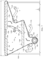
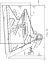
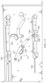
- FIGURE 7 , FIGURE 8 , and FIGURE 11 illustrate the pivoting mechanism 114 and the sliding support surfaces 116 in an extended position such that an overall upper length "L" of a travel path of the belt(s) 106 is extended (“L1"). This may permit items traveling along the belt(s) 106 to be passed along to an acceptance area, such as to an adjacent conveyor, bin, ramp, and/or machine.
- FIGURE 9 , FIGURE 10 , and FIGURE 12 illustrate the pivoting mechanism 114 and the sliding support surfaces 116 in a retracted position such that the overall upper length "L” of the travel path of the belt(s) 106 is reduced relative to the extended position ("L2").
- FIGURE 13 in particular, illustrates the pivoting mechanism 114 in a disengaged position such that the members 120 and/or posts 130 are removed from the sliding support surfaces 116.
- This may permit easy removal of the sliding support surfaces 116, and/or other components of the pivoting mechanism 114 and/or sorting device 100.
- the belt(s) 106 may be slackened, such as by movement of the rollers 110, and/or removed to facilitate removal of the sliding support surfaces 116.
- the adjacent axel 122 may serve to frictionally engage rotating ones of the members 120 and prevent over rotation in the disengaged position, though such is not required.
- the structural subassembly 104 may comprise channels 112 configured to permit movement of the rollers 110, such as to slacken and/or permit removal of the belts 106 and/or other various components of the sorting device 100, including, but not limited to, the rollers 110.
- Channels 112A, 112B, 112C may be provided for each of the rollers 110A, 110B, 110C, respectively, though such is not required.
- Post 111 may provide mounting points for bearings that support, and/or form part of, the drive subassembly 108.
- posts 111A, 111B may be provided on either side of structural subassembly 104, such as to fix bearings 109 to structural subassembly 104A, 104B while allowing drive subassembly 108 to rotate within the bearings and drive the belt(s) 106.
- One or more shields 128 may be provided, such as within the area defined by the travel path of the belt(s) 106. The shields 128 may be provided to protect various components from debris, by way of non-limiting example.
- the sliding support surfaces 116 may comprise one or more holes for weight reduction and/or balancing.
- the plate 140 may be pivotably connected to the structural subassembly 104, such as by way of one or more pivots 142, which may comprise any type or kind of fastener in exemplary embodiments, without limitation.
- the plate 140 may be rotatable relative to the structural subassembly 104 and/or the actuator 134 as further described herein.
- a plunger subassembly 144 may connect the plate 140 to an aperture 146 in the structural subassembly 104.
- the plunger subassembly 144 may comprise a handle portion 145, for manual engagement, and a shaft portion 162.
- the shaft portion 162 may comprise a spring-loaded pin 147 which is normally extended and may be selectively retractable, such as by way of manual actuation of the handle portion 145, to engage/disengage the aperture 146.
- the apertures 146 may be located to position the actuator 134 at a distance where actuation of the operable portion 136 causes rotational movement of the pivoting mechanism 114 between the retracted and extended positions, but preferably restrains the pivoting mechanism 114 from movement into the disengaged position.
- the plunger subassembly 144 may be a weldment including the pin 138, plate 140, handle portion 145, and/or shaft portion 162 by way of non-limiting example.
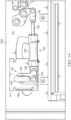
- the actuator 134 may be selectively disengaged, such as shown with particular regard to FIGURE 16 .
- the handle 145 may be manually actuated to move the shaft portion 162 out of the aperture 146, thereby permitting manual rotation of the plunger subassembly 144 rearward, thereby rotating the plate 140 and pulling the actuator 134 rearward. This may cause, or permit, the pivoting mechanism 114 to become disengaged from the sliding support surfaces 116, such as illustrated with particular regard to FIGURE 13 .
- the bracket 141 or structural subassembly 104 may comprise a stop 149 placed to prevent the plunger subassembly 144 from over rotation.
- the plunger subassembly 144 may be manually returned to engage the aperture 146, thereby causing, or permitting, the pivoting mechanism 114 to become engaged from the sliding support surfaces 116 and securing the actuator 134 for actuation. Where the plunger subassembly 144 is left disengaged from the aperture 146, normal operations may cause the actuator 134 to move forward, and the spring-loaded nature of the shaft portion 162 of the plunger subassembly 144 may cause automatic reengagement with the aperture 146.
- the operable portion 136 of the actuator 134 may be periodically extended or retracted to move the pivoting mechanism 114 and thus cause reciprocating movement of the sliding support surfaces 116.
- operation of the actuator 134 may be electronically controlled by wired and/or wireless connection with one or more controllers, such as may be located in the cabinet 155, elsewhere at the device 100, and/or remote therefrom.
- the actuator 134 may comprise a hydraulic piston, pneumatic piston 139, linear motor, combinations thereof, or the like.
- the pivoting mechanisms 114 may be directly or indirectly driven by one or more motors.
- the sorting device 100 may comprise multiple pivoting mechanisms 114A, 114B, such as but not limited to for multiple belts 106A, 106B.
- the pivoting mechanisms 114 may be independently controlled, such as by way of separate actuators 134, axels 122, controller, and/or related components in exemplary embodiments.
- the pivoting mechanisms 114 may be controlled by a common actuator 134, axel 122, controller, and/or related components in other exemplary embodiments.
- the belt(s) 106 may be driven, at least primarily, by a drive subassembly 108.
- the drive subassembly 108 may comprise one or more motors and/or gears (internal to item 153) and/or bearings 109 connected to one or more shafts.
- the drive subassembly 108 may be common to all belt(s) 106, though such is not required.
- An additional structural subassembly portion 104C may extend between each of the multiple belts 106.
- the additional structural subassembly portion 104C may serve as a partition.
- the device 100 may comprise a single lane or multiple lanes, which are preferably independently operable at least with regard to the sliding support surfaces 116, to accept or reject product.
- the device 100 may comprise 1, 2, 3, 4, etc. number of lanes and associated components.
- the belts 106 of all of the lanes may be commonly driven, though each lane may have an independently operable pivoting mechanism 114 for accepting/rejecting items on a per-lane basis.
- shafts of the drive subassembly 108 may extend internal to a structural subassembly 162, though such is not necessarily required.
- the illustrated structural subassembly 162 may serve as a shaft in other exemplary embodiments.
- the shaft need not necessarily be round.
- a number of belt engagement components 150A, 150B, 150C, 150D such as but not limited to sprockets, may be provided which rotate with the motor.
- the belt engagement components 150 may comprise one or more teeth or other protrusions for engaging the belt(s) 106.
- two belt engagement components 150 are provided for each belt 106, though any number, type, kind, and/or arrangement of belt engagement components 150 may be utilized.
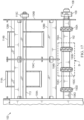
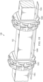
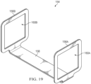
- the belt engagement components 150 may be spaced apart by spacers 154, which are further illustrated in at least FIGURE 19 .
- the spacers 154 may comprise openings 160A, 160B on either end for the structural subassembly/shaft 162 defined by substantially square and/or rectangular shaped brackets 156A, 156B, though any size or shape brackets 156 and/or openings 160 may be provided.
- a member 158 may connect the brackets 156.
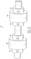
- the spacers 154 may be relatively open, easy to clean, and/or reduce the number of locations where microbes or other material may become lodged, such as compared to known solutions of FIGURE 20 and/or FIGURE 21 which use retainer rings 18A-18C for sprockets 15A, 15B and/or shaft collars 34A-34D for drive wheels 36A, 36B.
- the spacers 154 may, alternatively or additionally, be stronger and/or more reliable than known solutions, thereby reducing the likelihood of dislodgement, failure, or the like.
- retainer rings 18A-18C and/or shaft collars 34A-34D may be used in the alterative or in addition to the spacers 154.
- the device 100 may be at least partially disassembled and reassembled rapidly, such as for washdown or other cleaning.
- the rollers 110 may be moved within the apertures 112 to slacken the belt(s) 106, and optionally removed.
- the belt(s) 106 which may be modular or otherwise, may be removed.
- the actuator(s) 134 may be placed in the disengaged position such that the pivoting mechanisms 114 are disengaged from, or able to be disengaged from, the sliding support surfaces 116, which may be slid out of the structural subassembly 104.
- the normally stationary support surfaces 105 may be also removed. Additional components may be optionally removed.
- the removed parts may optionally be stored at one or more storage areas for washdown and/or cleaning, such as one or more cubbies, slots, hangers, or the like provided in the support structure 102 by way of non-limiting example.
- the remaining portions of the device 100 may optionally be cleaned and/or serviced.
- Reassembly may be provided in reverse. These steps may be provided in various orders and/or certain steps may be omitted and/or repeated. Disassembly and/or assembly in this regard may be completed in less than a minute and/or less than 5 minutes, by way of non-limiting example, by a knowledgeable technician.
- the components may be configured to be accepted and/or usable in various orientations. This may provide for easier assembly/reassembly and/or provide multiple wear surfaces.
- the sliding support surfaces 116 may be configured for acceptance and/or use in multiple orientations.
- apertures 132A may be provided at more than one end of the upper sliding support surfaces 116A. This may permit multiple orientations of the upper sliding support surfaces 116A for use while also allowing for multiple wear surfaces.
- the apertures 132 may extend through the sliding support surfaces to permit multiple orientations and/or provide multiple wear surfaces.
- the normally stationary support surfaces 105 may be at least partially symmetrical to provide for multiple orientations and/or wear surfaces. This may, alternatively or additionally, permit manual, tool-less disassembly and/or reassembly.
- the configuration of the actuators 134 and other components of the device 100 may provide a relatively low, end force at the sliding support surfaces 116, particularly the upper sliding support surfaces 116A, such as at or under 20 pounds of force by way of non-limiting example.
- the device 100 may have few to no fasteners (e.g., screws, nails, bolts, etc.) internal to the area defined by the travel path of the belt.
- fasteners e.g., screws, nails, bolts, etc.
- the following embodiments of the sorting device 100 are provided by way of non-limiting example.
- the sorting device 100 comprises a conveyor belt 106, sliding support surfaces 116 at least partially supporting the conveyor belt 106, and a pivoting mechanism 114 connecting the sliding support surfaces 116 and configured to selectively pivot to cause reciprocating movement of the sliding support surfaces 116 to adjust a length of an upper portion of a travel path for the conveyor belt 106.
- the sliding support surfaces 116 comprise an upper sliding support surface 116A and a lower sliding support surface 116B.
- the pivoting mechanism may comprise an axel 122 and members 120.
- the axel 122 is located between the upper sliding support surface 116A and the lower sliding support surface 116B.
- Each of said members 120 extend from the axel 122 to both of the upper sliding support surface 116A and the lower sliding support surface 116B.
- the pivoting mechanism 114 comprises posts 130 connecting the members 120.
- the posts 130 each extend between a respective end portion of the members 120.
- Each of the upper sliding support surface 116A and the lower sliding support surface 116B comprise one or more apertures 132 configured to accommodate the respective end portion of the members 120 and a respective one of the posts 130.
- the structural subassembly 104 comprises a first portion 104A and a second portion 104B, wherein the axel 122 extends between the first and second portions 104A, 104B of the structural subassembly 104 and the members 120 are located between the first portion and the second portion 104A, 104B of the structural subassembly 104.
- Protrusions 118 are located at the structural subassembly 104, wherein the first and second sliding support surfaces 116A, 116B each comprise channels configured to accommodate the protrusions 118, wherein the protrusions 118 support the first and second sliding support surfaces 116A, 116B during the reciprocating movement.
- An actuator 134 controls the reciprocating movement of the sliding support surfaces 116, wherein the actuator 134 is located outside of an area defined by the travel path of the conveyor belt 106.
- a plate 140 connects to the actuator 134 and the structural subassembly 104 in a rotatable fashion, where rotation of the plate 140 causes movement of the actuator 134 sufficient to disengage the pivoting mechanism 114 from the sliding support surfaces 116.
- the actuator 134 comprises a pneumatic piston.
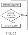
- the actuator 134 is in electronic communication with a controller and is configured to actuate an operable portion 136 upon receipt of a reject signal from the controller.
- the actuator 134 is connected to the plate 140 by way of the pin 138.
- the actuator 134 is connected to the axel 122 by way of a crank arm 151 and a pivoting member 143.
- a drive subassembly 108 comprises a shaft 162, spacers 154, and belt engagement components 150.
- the belt engagement components 150 are spaced apart along the shaft 162 by way of the spacers 154.
- the spacers 154 comprise brackets 156 with openings 160 sized to accommodate the shaft 162 and a member 158 connecting the brackets 156.
- the spacers 154 comprise brackets 156 located at either end thereof to define openings.
- the shaft 162 comprises a cross sectional shape complementary to the openings 160.
- the member 158 comprises a thin strip extending between the brackets 156.
- the belt engagement components 150 comprise sprockets.
- the device 100 may comprise a second upper sliding support surface 116, a second lower sliding support surface 116, a second conveyor belt 106B, and a third structural subassembly portion 104C, which may be located between the first structural subassembly portion 104A and the second structural subassembly portion 104B.
- the protrusions 118 are located at each of the first, second, and third structural subassembly portions 104A, 104B, 104C. Both of the upper sliding support surface 116A and the lower sliding support surface 116B extend between the first structural subassembly portion 104A and the third structural subassembly portion 104C. Both of the second upper sliding support surface 116A and the second lower sliding support surface 116B extend between the third structural subassembly portion 104C and the second structural subassembly portion 104B.
- the device 100 may include a second pivoting mechanism 114B comprising a second set of members 120, a second axel 122, and a second set of posts 130.
- a second actuator 134 may be connected to the second axel 122, where the pivoting mechanism 114 is located between the first structural subassembly portion 104A and the third structural subassembly portion 104C.
- the second pivoting mechanism 114B is located between the second structural subassembly portion 104B and the third structural subassembly portion 104C.
- the actuator 134 and the second actuator 134B are independently operable.
- the device 100 may comprise a drive subassembly 108 engaging the conveyor belt 106A, a normally stationary support surface 105 engaging the conveyor belt 106. Rollers 110 engaging the conveyor belt 106, a structural subassembly 104, wherein the sliding support surfaces 116, the drive subassembly 108, the normally stationary support surface 105, the rollers 110, and the pivoting mechanism 114 are at least partially supported by the structural subassembly 104.
- a support structure 102 at least partially supporting the structural subassembly 104.
- Channels 112 may be provided in the structural subassembly 104 for moving the rollers 110 to slacken the conveyor belt 106.
- the sliding support surfaces 116 are configured for substantially parallel, horizontal movement.
- the sorting device 100 includes a structural subassembly 104, a conveyor belt 106 located at a first side of a first portion of the structural subassembly 104A, where a portion of a travel path for the conveyor belt 106 is oriented to accommodate objects for sorting.
- the device 100 may further include a drive subassembly 108 engaging the conveyor belt 106, rollers 110 engaging the conveyor belt 106, upper and lower sliding support surfaces 116A, 116B located at the first side of the first portion of the structural subassembly 104 and at least partially supporting the conveyor belt 106.
- the device 100 may further include a pivoting mechanism 114 located at the first side of the first portion of the structural subassembly 104A, said pivoting mechanism 114 comprising an axel 122 and members 120 extending from the axel 122 to the upper and lower sliding support surfaces 116A, 116B.
- a pivoting mechanism 114 located at the first side of the first portion of the structural subassembly 104A, said pivoting mechanism 114 comprising an axel 122 and members 120 extending from the axel 122 to the upper and lower sliding support surfaces 116A, 116B.
- the device 100 may further include an actuator 134 located at a second side of the first portion of the structural subassembly 104A, said actuator 134 mechanically linked to the pivoting mechanism 114 such that, when said actuator 134 is operated, the pivoting mechanism 114 pivots, resulting in reciprocating movement of the upper and lower sliding support surfaces 116A, 116B to change a length of the portion of the travel path of the conveyor belt 106 oriented to accommodate the objects for sorting.
- an actuator 134 located at a second side of the first portion of the structural subassembly 104A, said actuator 134 mechanically linked to the pivoting mechanism 114 such that, when said actuator 134 is operated, the pivoting mechanism 114 pivots, resulting in reciprocating movement of the upper and lower sliding support surfaces 116A, 116B to change a length of the portion of the travel path of the conveyor belt 106 oriented to accommodate the objects for sorting.
- the drive subassembly 108 comprises a shaft 162, a motor for rotating the shaft 162 (the motor and/or gears for the same may be located internal to housing 153 by way of non-limiting example), belt engagement components 150 located along the shaft 162 and engaging the conveyor belt 106, and spacers 154 located along the shaft 162 between the belt engagement components.
- the actuator 134 comprises a pneumatic piston and is mechanically linked to the axel 122 by way of a lever arm 151 and a pivoting member 143.
- the actuator 134 is connected to said structural subassembly 104 in a manner which permits spatial translation of the actuator 134 to cause further rotation of the axel 122 and disengagement of the pivoting mechanism 114 from the upper and lower sliding support surfaces 116A, 116B.
- the sorting device 100 includes a structural subassembly 104, a support structure 102 for the structural subassembly 104, a conveyor belt 106 having a travel path, an upper portion of said travel path oriented to accommodate goods to be sorted, a drive subassembly 108 engaging the conveyor belt 106, rollers 110 engaging the conveyor belt 106, said rollers 110 disposed within channels 112 provided at the structural subassembly 104 which permit manual movement of the rollers 110, upper and lower sliding support surfaces 116A, 116B at least partially supporting the conveyor belt 106, wherein the upper sliding support surface 116A at least partially defines the upper portion of said travel path, a normally stationary support surface 105 at least partially defining the upper portion of said travel path, a pivoting mechanism 114 provided within an area defined by the travel path of the conveyor belt 106, said pivoting mechanism 114 comprising an axel 122 and members 120 extending from the axel 122 to the upper and lower
- the device 100 may further include protrusions 118 on the structural subassembly 104, and channels on the upper and lower sliding support surfaces 116A, 116B, wherein the protrusions 118 are received within the channels of the upper and lower sliding support surfaces 116A, 116B to constrict travel of the upper and lower sliding support surfaces 116A, 116B to reciprocating, lateral, substantially parallel sliding movement and permit sliding removal of the upper and lower sliding support surfaces 116A, 116B from the structural subassembly 104 when the conveyor belt 106 is removed.
- the normally stationary support surface 105 may be retained by slots in the structural subassembly 104, such as but not limited to in the first and second portions 104A, 104.
- the slots may permit sliding removal of the normally stationary support surface 105 from the structural subassembly 104 when the conveyor belt 106 is removed.
- the normally stationary support surfaces 105 may comprise protrusions, channels, or the like configured to interact with the slots, such as to support the normally stationary support surfaces 105 and/or permit sliding movement thereof.
- the drive subassembly 108 may include the shaft portion 162, which may be driven, and the spacers 154 for spacing belt engagement portions along the shaft 154.
- the actuator 134 may be connected to the structural subassembly 104 by way of a rotational plate 140 such that rotation of the plate 140 in a first direction is configured to move the actuator 134 and cause the pivoting mechanism 114 to be disengaged from the upper and lower sliding support surfaces 116A, 116B.
- any embodiment of the present invention may include any of the features of the other embodiments of the present invention.
- the exemplary embodiments herein disclosed are not intended to be exhaustive or to unnecessarily limit the scope of the invention.
- the exemplary embodiments were chosen and described in order to explain the principles of the present invention so that others skilled in the art may practice the invention. Having shown and described exemplary embodiments of the present invention, those skilled in the art will realize that many variations and modifications may be made to the described invention. Many of those variations and modifications will provide the same result and fall within the spirit of the claimed invention.
- Each electronic device may comprise one or more processors, electronic storage devices, executable software instructions, combinations thereof, and the like configured to perform the operations described herein.
- the electronic devices may be general purpose computers or specialized computing devices.
- the electronic devices may comprise personal computers, smartphone, tablets, databases, servers, or the like.
- the electronic connections and transmissions described herein may be accomplished by wired or wireless means.
- the computerized hardware, software, components, systems, steps, methods, and/or processes described herein may serve to improve the speed of the computerized hardware, software, systems, steps, methods, and/or processes described herein.
- the electronic devices including but not necessarily limited to the electronic storage devices, databases, controllers, or the like, may comprise and/or be configured to hold, solely non-transitory signals.
Landscapes
- Engineering & Computer Science (AREA)
- Mechanical Engineering (AREA)
- Discharge Of Articles From Conveyors (AREA)
- Branching, Merging, And Special Transfer Between Conveyors (AREA)
Abstract
A sorting device (100) operates to shorten or lengthen a length of an upper portion of a travel path for a conveyor belt (106) by reciprocating movement of sliding support surfaces (116) at least partially supporting the conveyor belt (106). The reciprocating movement of the sliding support surfaces (116) caused by rotational movement of a connected pivoting mechanism (114), which may be operated by an actuator (134) located outside of an area defined by the travel path for the conveyor belt (106).
Description
- Exemplary embodiments relate generally to a sorting device, such as which operates by reciprocating sliding movement to adjust a length of a portion of a conveyor to accept or reject items, as well as systems and methods related to the same.
- Various sorting devices are known. It may be desirable to periodically washdown such sorting devices, particularly when used for product or applications where hygiene is especially important, such as but not limited to where the sorting device is interacting with foodstuffs (e.g., poultry by way of non-limiting example). Adequate washdown, drying, and/or other cleaning can be difficult where small gaps are provided, fasteners are utilized, or other small cracks and crevices exist, which may trap water and/or particulate, which may permit microbial growth. This may be particularly important in areas where product may be encountered. Regardless, such devices may require periodic maintenance. Reducing part count and improving removability and reassembly of parts may improve maintenance efforts. This may also reduce the potential for part failure or dislodgement. Therefore, what is needed is a sorting device which addresses these, and other, concerns.
- A sorting device and related systems and methods are disclosed which address these, and other, shortcomings in the art. For example, the disclosed sorting device and related systems and methods minimize the use of fasteners and small cracks and crevices, particularly in areas where objects are normally encountered. As another example, the disclosed sorting device and related systems and methods provide ease of component removal and replacement. As yet another example, the disclosed sorting device and related systems and methods provide several components which are capable of being attached and operated in various orientations.
- The disclosed sorting devices and related systems and methods may include reciprocating sliding support surfaces which operate to retract and extend conveyor belts while maintaining adequate belt tension. A pivoting mechanism may be provided which facilitates the reciprocating movement of upper and lower ones of the sliding support surfaces. The pivoting mechanisms may be selectively driven by an actuator located outside an area of travel for the conveyor belt, which may minimize areas where pieces of handled objects may become lodged. In exemplary embodiments, the actuator is connected, by way of an arm and/or a pivoting device, to an axel which is rotated with movement of the actuator. The axel may support multiple members, which extend therefrom to engage, such as by way of posts extending between the members, the sliding support surfaces. Upper ends of the members and/or the posts may be received within apertures at the upper and lower sliding support surfaces.
- Multiple sets of upper and lower sliding support surfaces, pivoting mechanisms, actuators, conveyor belts, and the like may be provided at a given sorting device to provide multiple, independently operable, lanes for product sorting.
- Each of the actuators may be connected to the respective linkage by a respective pivoting member and/or linkage arm, though such is not necessarily required. This may allow selective separation of a first, operable end of the actuator and/or various mechanical advantages or disadvantages. A second end of the actuator may be connected to a structural subassembly by way of a plate, which is configured for rotational movement about a pivot. Rotation of the plate may be accomplished by manual operation of a spring plunger to disengage the plunger from the structural subassembly and permit manual rotation of the plate, and the connected actuator, rearward. This rearward movement of the actuator may cause further rotation of the axel (e.g., by way of the arm and/or pivoting device) and movement of the pivoting device out of engagement with the sliding support surfaces. The actuators may be connected to the plates by way of one or more pins for easy removal.
- The sliding support surfaces may comprise channels which engage protrusions at the structural subassembly and limit travel of the sliding support surfaces to substantially parallel, horizontal movement.
- Rollers may be provided within channels of the structural subassembly to permit easy movement for slackening and removing the conveyor belts, such as for separate washing or other cleaning. Disengagement of the pivoting mechanisms from the sliding support surfaces may permit removal of the sliding support surfaces, such as along the protrusions, from the structural subassembly, such as for separate washing or other cleaning. A normally stationary support surface may likewise be mounted and removed, such as by way of additional protrusions on the structural subassembly.
- The disclosed sorting devices and related systems and methods may permit tool-less, rapid removal and replacement of at least the sliding support surfaces, normally stationary support surfaces as well as the pivoting mechanisms, actuators, and/or other components of the sorting devices.
- A drive subassembly may comprise a shaft with spacers for maintaining spacing of sprockets along the shaft. The spacers may comprise brackets with apertures sized for the shaft and a member connecting the brackets. This provides a relatively open design over known solutions, such as snap rings and collars, thereby providing relatively easy cleaning and minimizing spaces for microbes or other material to be harbored. The spacers may also reduce the potential for failure or dislodgement of such components within a travel path area of the conveyor.
- The disclosed sorting devices and related systems and methods may require fewer parts. The sorting devices may contain no bolts, nuts, washers, or actuators at least within a zone interior to the conveyor belt. The sorting devices may comprise parts which are orientation independent such that they may be inserted and/or attached in multiple orientations. The sorting devices may have moving parts with relatively low weight to lower inertia for quick activation and reactivation time.
- A further one of such a sorting device may comprising a structural subassembly; a conveyor belt located at a first side of a first portion of the structural subassembly, a portion of a travel path for the conveyor belt oriented to accommodate objects for sorting; a drive subassembly engaging the conveyor belt; rollers engaging the conveyor belt; upper and lower sliding support surfaces located at the first side of the first portion of the structural subassembly and at least partially supporting the conveyor belt; a pivoting mechanism located at the first side of the first portion of the structural subassembly, said pivoting mechanism comprising an axel and members extending from the axel to the upper and lower sliding support surfaces; and an actuator located at a second side of the first portion of the structural subassembly, said actuator mechanically linked to the pivoting mechanism such that, when said actuator is operated, the pivoting mechanism pivots, resulting in reciprocating movement of the upper and lower sliding support surfaces to change a length of the portion of the travel path of the conveyor belt oriented to accommodate the objects for sorting.
- In said sorting device, the drive subassembly may comprise a shaft, a motor for rotating the shaft, belt engagement components located along the shaft and engaging the conveyor belt, and spacers located along the shaft between the belt engagement components. Or the actuator comprises a pneumatic piston; and the actuator is mechanically linked to the axel by way of a lever arm and a pivoting member. Or the actuator is connected to said structural subassembly in a manner which permits spatial translation of the actuator to cause further rotation of the axel and disengagement of the pivoting mechanism from the upper and lower sliding support surfaces.
- Another one of such a sorting device may comprising a structural subassembly; a support structure for the structural subassembly; a conveyor belt having a travel path, an upper portion of said travel path oriented to accommodate goods to be sorted; a drive subassembly engaging the conveyor belt; rollers engaging the conveyor belt, said rollers disposed within channels provided at the structural subassembly which permit manual movement of the rollers; upper and lower sliding support surfaces at least partially supporting the conveyor belt, wherein the upper sliding support surface at least partially defines the upper portion of said travel path; a normally stationary support surface at least partially defining the upper portion of said travel path; a pivoting mechanism provided within an area defined by the travel path of the conveyor belt, said pivoting mechanism comprising an axel and members extending from the axel to the upper and lower sliding support surfaces; a controller; an actuator located outside of the area defined by the travel path of the conveyor belt, electronically connected to the controller, and mechanically connected to the pivoting mechanism by at least a crank arm and a pivoting member, wherein said actuator, following receipt of a rejection signal from the controller, actuates to cause rotation of the axel, resulting in rotational movements of the members, retraction of the upper sliding support surface, and reciprocating extension of the lower sliding support surface to shorten a length of the upper portion of the travel path for the conveyor belt to cause the objects traveling thereon to be deposited into a rejection area and maintain tension in the conveyor belt; protrusions on the structural subassembly; channels on the upper and lower sliding support surfaces, wherein the protrusions are received within the channels of the upper and lower sliding support surfaces to constrict travel of the upper and lower sliding support surfaces to reciprocating, lateral, substantially parallel sliding movement and permit sliding removal of the upper and lower sliding support surfaces from the structural subassembly when the conveyor belt is removed; and slots located at the support structure configured to receive the normally stationary support surface and permit sliding removal of the normally stationary support surface from the structural subassembly when the conveyor belt is removed.
- Further features and advantages of the systems and methods disclosed herein, as well as the structure and operation of various aspects of the present disclosure, are described in detail below with reference to the accompanying figures.
- In addition to the features mentioned above, other aspects of the present invention will be readily apparent from the following descriptions of the drawings and exemplary embodiments, wherein like reference numerals across the several views refer to identical or equivalent features, and wherein:
- Fig. 1
- is a side perspective view of an exemplary prior art sorting device;
- Fig. 2
- is a top perspective view of the sorting device of
figure 1 with the conveyor belt removed; - Fig. 3
- is a perspective view of an internal area of an exemplary prior art sorting device;
- Fig. 4
- is a left-side perspective view of an exemplary sorting device in accordance with the present invention;
- Fig. 5
- is a right-side perspective view of the sorting device of
figure 4 ; - Fig. 6
- is a rear view of the sorting device of
figure 4 ; - Fig. 7
- is side sectional view of the sorting device of
figure 4 with a pivoting mechanism in an extended position; - Fig. 8
- is a perspective sectional side view of the sorting device of
figure 7 ; - Fig. 9
- is a side sectional view of the sorting device of
figure 4 with a pivoting mechanism in a retracted position; - Fig. 10
- is a perspective sectional side view of the sorting device of
figure 9 ; - Fig. 11
- is a detailed sectional side view of Detail A of
figure 8 ; - Fig. 12
- is a detailed sectional side view of Detail B of
figure 10 ; - Fig. 13
- is a detailed sectional side view of
figures 11-12 with the pivoting mechanism in a disengaged position; - Fig. 14
- is a detailed side view of Detail C of
figure 6 with an actuator for the sorting device offigure 4 in an engaged position; - Fig. 15
- is a detailed top perspective view of the actuator of
figure 14 in the engaged position; - Fig. 16
- is a detailed top perspective view of the actuator of
figure 14 in a disengaged position; - Fig. 17
- is a detailed front view of the sorting device of
figure 4 with conveyor belts and other components removed to more clearly illustrate other certain components thereof; - Fig. 18
- is a detailed front perspective view of Detail D of
figure 17 with a drive subassembly of the sorting device offigure 4 ; - Fig. 19
- is a perspective view of spacers of the drive subassembly of
figure 17 shown in isolation; - Fig. 20
- is a detailed perspective view of an exemplary prior art drive subassembly;
- Fig. 21
- is a detailed perspective view of another exemplary prior art drive subassembly; and
- Fig. 22
- is a flow chart with exemplary logic for operating the sorting device of
figure 4 . - Various embodiments of the present invention will now be described in detail with reference to the accompanying drawings. In the following description, specific details such as detailed configuration and components are merely provided to assist the overall understanding of these embodiments of the present invention. Therefore, it should be apparent to those skilled in the art that various changes and modifications of the embodiments described herein can be made without departing from the scope and spirit of the present invention. In addition, descriptions of well-known functions and constructions are omitted for clarity and conciseness.
- Embodiments of the invention are described herein with reference to illustrations of idealized embodiments (and intermediate structures) of the invention. As such, variations from the shapes of the illustrations as a result, for example, of manufacturing techniques and/or tolerances, are to be expected. Thus, embodiments of the invention should not be construed as limited to the particular shapes of regions illustrated herein but are to include deviations in shapes that result, for example, from manufacturing.
-
FIGURE 1 through FIGURE 3 illustrate exemplary knownsorting devices 10. Aconveyor belt 18 is extended about a number ofrollers 16A-16D and adriver 20, which is motorized and comprise sprockets for driving thebelt 18. Anupper support platform 12 comprises a number of members configured for relative sliding movement to shorten an overall upper length of a travel path for theconveyor belt 18 and cause items to be dropped onto arejection chute 22. To take upbelt 18 slack during such retraction, anactuator 14 is operated to adjust a spatial position of at least one of therollers 16C. The actuator is mounted internal to a travel path of thebelt 18. A large number of fasteners are used to create theupper support platform 12. -
FIGURE 4 andFIGURE 5 illustrate asorting device 100 in accordance with the present invention. Thesorting device 100 may comprise, or be attachable to, asupport structure 102, though such is not required. Thesupport structure 102 may comprise one or more members, one or more adjustable legs, one or more platforms, one or more members, plates, housings, combinations thereof, or the like. Thesupport structure 102 may be configured for mounting or connection to other structures, though such is not required. - The
sorting device 100 may comprise a structural subassembly 104. The structural subassembly 104 may comprise one or more panels, plates, members, combinations thereof, or the like. The structural subassembly 104 may comprise afirst portion 104A and asecond portion 104B. The first andsecond portions device 100. The structural subassembly 104 may comprise any number, size, and/or shape portions. Various components of thedevice 100, such as but not limited to rollers 110 and/or adrive subassembly 108, may be connected to the structural subassembly 104, in exemplary embodiments, such as at thefirst portion 104A. Thesecond portion 104B may, for example, enclose an area device by conveyor belt(s) 106.Additional portions 104C may extend within and/or outside of the area defined by the travel path of conveyor belt(s) 106 of thedevice 100, such as to extend between and/or divide multiple belts 106, thereby defining lanes for objects to be sorted by thedevice 100. - The
sorting device 100 may comprise one or multiple belts 106, though such is not required. Adrive subassembly 108 may be provided which engages, supports, directs, and/or drives the belt(s) 106. Each of the belt(s) 106 may be further supported, engaged, and/or directed by one or more rollers 110. Thedrive subassembly 108 may extend between, and/or be supported by, the first and secondstructural subassembly portions third roller structural subassembly portions drive subassembly 108 and/or the rollers 110 may be common to all belts 106 for a givendevice 100, though such is not required. Thedrive subassembly 108 and/or the rollers 110 may direct and define a travel path for the belt(s) 106. In other exemplary embodiments, the rollers 110 may comprise posts which are stationary and engage and/or direct the belt(s) 106. For example, the posts may be employed to maintain the belt(s) 106 adjacent to thedrive subassembly 108, such as to assist with frictional engagement. - The sorting device may comprise one or more normally stationary support surfaces 105. The normally stationary support surfaces 105 may support, engage, and/or direct the belt(s) 106. The normally stationary support surfaces 105 may comprise rollers, though such is not required. The normally stationary support surfaces 105 may extend between, and/or be supported by, the first and second
structural subassembly portions - As further described herein, at least the normally stationary support surfaces 105, rollers 110, and/or belt(s) 106 may be easily removed and/or reinserted to the structural subassembly 104 of the
device 100, such as for washdown or other cleaning, inspection, and/or replacement. - A portion of the travel path of the belt(s) 106, such as but not limited to an upper portion, may be configured to accommodate goods for sorting. For example, without limitation, the upper portion of the travel path of the belt(s) 106 may be relatively flat, extend substantially parallel to a ground surface, and/or be sufficiently oriented to maintain frictional engagement with, and convey, goods under gravitational forces, though such is not required. A remaining portion of the travel path of the belt(s) 106 may be sinuous and/or not oriented to maintain frictional engagement with, and convey, goods under gravitational forces when the
device 100 is properly oriented. However, any shape or configuration of the travel path may be utilized. The upper portion, or other product supporting portion, of the travel path of the belt(s) 106 may be supported by at least the normally stationary support surfaces 105 and an upper one or ones of the slidingsupport surfaces 116A, which may serve to support the belt(s) 106 and/or the objects to be sorted. - As illustrated with particular regard to at least
FIGURE 6 , thedevice 100 may comprise one ormore actuators 134. In exemplary embodiments, without limitation, the actuator(s) 134 are provided at a given side of the structural subassembly 104 and/or outside of the area defined by the travel path of the belt(s) 106. For example, without limitation, the actuator(s) 134 are provided at a first side of a firststructural subassembly portion 104A. In this way, theactuators 134 may be located outside the area defined by the travel path of the belt(s) 106 and/or may be at least partially shielded from the objects being sorted. This arrangement may also eliminate a need to string air or other lines through the area defined by the travel path of the belt(s) 106. - The
actuators 134 may each be attached to a respective axel 122. In exemplary embodiments, a first, operable end of theactuators 134 are each attached to the respective axel 122 by way of a linkage 151. The linkage 151 may be an arm, such as a crank and/or lever arm. - The linkage 151 may be connected to the actuator by way of a pivoting
member 143. The pivotingmember 143 may be pivotably connected to the linkage 151. The pivotingmember 143 may comprise a generally cuboid shape portion having a recess configured to receive the first end of theactuators 134. However, any size and/or shape may be utilized. The pivotingmember 143 may be mechanically separated from theactuator 134, though such is not required. In other exemplary embodiments, without limitation, the pivotingmember 143 is permanently connected to theactuator 134. - The
actuator 134 may be connected to the structural subassembly 104 by way of abracket portion 141, though such is not required. In exemplary embodiments, without limitation, anactuator 134, axel 122 and related components (e.g., linkage 151, pivoting member 143) and provided for each belt 106 of thedevice 100 such that each belt 106 is independently operable. However, a single axel 122,actuator 134, and related components could be utilized to control multiple belts 106. - Operation of the
actuator 134 may be configured to cause rotational movement of the axel 122, such as by way of the linkage 151 and/or pivotingmember 143, which may be connected to the axel 122. Operation of theactuator 134 and related components is more fully described herein. - The
device 100 may comprise one or more motors and/or gears, such as may be located within ahousing 153. The motor(s), gear(s) and/or housing(s) 153 may be located at a same side of the structural subassembly 104 as theactuators 134. In this way, the motors and/or gears may be located outside of an area defined by the travel path of the belt(s) and/or otherwise partially shielded by the first portion of thestructural subassembly 104A. The motors may be connected to thedrive subassembly 108, such as by way of one or more gears or other mechanical energy transfer devices. - The
device 100 may comprise one or more controllers, power supplies, circuit breakers, power transformers, and/or other electronic and/or electric equipment, such as may be located within one ormore cabinets 155, preferably located at a same side of the structural subassembly 104 as theactuators 134. In this way, the sensitive electronic and/or electric equipment may be located outside of an area defined by the travel path of the belt(s) and/or otherwise partially shielded by the first portion of thestructural subassembly 104A. The electronic and/or electric equipment may be in wired or wireless connection with various components of thedevice 100, including, but not limited to the drive subassembly 108 (e.g., to power and/or control the motor(s) thereof) and/oractuators 134. Power, data, and/or other lines may enter and/or exit thecabinet 155. - In exemplary embodiments, without limitation, the
device 100 may comprise at least twoactuators actuator bracket portion plate respective bracket portion respective pivot respective actuators respective plunger subassembly actuators axel respective pivoting member respective linkage - As further illustrated with particular regard to at least
FIGURE 7 through FIGURE 13 , the sorting device may comprise one ormore pivoting mechanisms 114. The pivoting mechanism(s) 114 may be internal to the area defined by the travel path of the belt(s) 106. - A
pivoting mechanism 114 may be provided for each belt 106 in exemplary embodiments, though such is not required. In this fashion, eachpivoting mechanism 114 may be independently operable, such as to provide independent rejection/acceptance for each belt 106 and lane of thedevice 100. - Each of the
pivoting mechanism 114 may comprise an axel 122. The axel 122 may pivotably support a set of one ormore members 120. In exemplary embodiments, without limitation,members 120 are provided for each belt 106. In other exemplary embodiments, asingle member 120 may be provided for each belt 106 and/or for all belts 106.Members 120 may be further connected by upper and/orlower posts members 120 may be connected to such upper and/orlower posts single member 120 may be provided for each belt 106 and/or for all belts 106. The axel 122 may be connected at a midportion (e.g., midpoint) of themembers 120 such that themembers 120 extend above and below the axel 122. Theupper post 130A being located towards an upper portion of themembers 120 and thelower post 130B being located towards a lower portion of themembers 120. Themembers 120 may have a curved shape, though any shape may be utilized. The curved shape may contribute todevice 100 balancing. The axels 122 may extend between, and/or be supported by, the first and secondstructural subassembly portions members 120, and set of upper and lower posts 130 are provided for each belt 106 of a givendevice 100, though other configurations may be utilized. - The pivoting
mechanisms 114 may engage sliding support surfaces 116. In exemplary embodiments, without limitation, an upper slidingsupport surface 116A and a lower slidingsupport surface 116B may be provided for each belt 106. The belt(s) 106 may engage, be directed, and/or be supported by at least part of the sliding support surfaces 116. In exemplary embodiments, the upper slidingsupport surface 116A and/or the normallystationary support surface 105 may provide support for the belts 106 and items placed thereon. The lower sliding support surfaces 116B may engage, support, and/or direct the belts 106. As further explained herein, the upper slidingsupport surfaces 116A may be moved laterally (e.g., by way of the pivoting mechanisms 114) to shorten and/or lengthen an upper portion of the travel path for the belt(s) 106 to provide acceptance/rejection of objects while the lower sliding support surfaces 116B may be reciprocally moved laterally to maintain tension on the belt(s) 106. This reciprocating arrangement may contribute to balancing of thedevice 100. Furthermore, the upper and lower slidingsupport surfaces device 100 during such movement. - In exemplary embodiments, the upper and lower sliding
support surfaces members 120 and/or posts 130. For example, without limitation, an upper portion of themembers 120 and theupper post 130A may be positioned within one ormore apertures 132A of the upper slidingsupport surface 116A while a lower portion of themembers 120 and thelower post 130B may be positioned within one ormore apertures 132B of the lower slidingsupport surface 116B. This may permit engagement with, and opposing lateral translation of, the upper and lower slidingsupport surfaces pivoting mechanism 114 is operated. The apertures 132 may have adequate size and/or shape (e.g., length and depth) to retain the upper and lower portions of themembers 120 and the upper and lower posts 130, respectively, within the respective sliding support surfaces 116 when the sliding support surfaces 116 are reciprocally moved, such as by way of theactuators 134. The apertures 132 may have adequate size and/or shape (e.g., length and depth) to cause removal and disengagement of themembers 120 and the upper and lower posts 130 from the sliding support surfaces 116, such as when theactuators 134 are moved into a disengagement position. - The sliding support surfaces 116 may slide along protrusions 118, which may act as tracks. The protrusions 118 may be provided at one or more of the structural subassembly 104 portions, such as the first
structural subassembly portion 104A, the secondstructural subassembly portion 104B, the thirdstructural subassembly portion 104C, or the like, though such is not required. The protrusions 118 may extend laterally and/or substantially horizontally. The sliding support surfaces 116 may comprise channels, such as in a side thereof, to accommodate the protrusions 118. In exemplary embodiments, without limitation, a set ofupper protrusions 118A are provided for the upper slidingsupport surface 116A and a set oflower protrusions 118B are provided for the lower slidingsupport surface 116B. Protrusions 118 may be provided at adjacent structural subassembly portions 104 to facilitate sliding movement of the sliding support services 116. - The protrusions 118 may be oriented to cause substantially parallel, horizontal, reciprocal sliding movement of the sliding support surfaces 116 when the
pivoting mechanism 114 is operated. The sliding support surfaces 116 and/or normallystationary support surface 105 may be oriented to extend substantially horizontally, though such is not required. While sliding movement is shown and/or described in some instances, such as for the sliding support surfaces 116, other types and/or kinds of movements may be utilized. In this fashion, travel of the sliding support surfaces 116 may be constricted to substantially lateral movement. As used herein to discuss relative angular relationships, "substantially" may be understood to mean within +/- 15 degrees unless otherwise indicated. - Where multiple pivoting
mechanisms 114 are employed, various components, such as but not limited to, the axel 122,members 120, posts 130, linkage 151, pivotingmember 143, and/oractuator 134 may be provided for each pivotingmechanisms 114. In other exemplary embodiments, without limitation, each of the pivotingmechanisms 114 may share certain components, including, but not limited to an axel 122,members 120, posts 130, linkage 151, pivotingmember 143, and/oractuator 134, though such is not required. -
FIGURE 7 ,FIGURE 8 , andFIGURE 11 , in particular, illustrate thepivoting mechanism 114 and the sliding support surfaces 116 in an extended position such that an overall upper length "L" of a travel path of the belt(s) 106 is extended ("L1"). This may permit items traveling along the belt(s) 106 to be passed along to an acceptance area, such as to an adjacent conveyor, bin, ramp, and/or machine.FIGURE 9 ,FIGURE 10 , andFIGURE 12 , in particular, illustrate thepivoting mechanism 114 and the sliding support surfaces 116 in a retracted position such that the overall upper length "L" of the travel path of the belt(s) 106 is reduced relative to the extended position ("L2"). This may permit items traveling along the belt(s) 106 to be selectively deposited into a rejection area, such as by dropping into a gap created by the retraction and/or onto a ramp, conveyor, bin, and/or machine below the gap, adjacent, combinations thereof, or the like. -
FIGURE 13 , in particular, illustrates thepivoting mechanism 114 in a disengaged position such that themembers 120 and/or posts 130 are removed from the sliding support surfaces 116. This may permit easy removal of the sliding support surfaces 116, and/or other components of thepivoting mechanism 114 and/or sortingdevice 100. The belt(s) 106 may be slackened, such as by movement of the rollers 110, and/or removed to facilitate removal of the sliding support surfaces 116. - Where
multiple axels multiple belts members 120 and prevent over rotation in the disengaged position, though such is not required. - The structural subassembly 104 may comprise channels 112 configured to permit movement of the rollers 110, such as to slacken and/or permit removal of the belts 106 and/or other various components of the
sorting device 100, including, but not limited to, the rollers 110.Channels rollers drive subassembly 108. For example, without limitation, posts 111A, 111B may be provided on either side of structural subassembly 104, such as to fixbearings 109 tostructural subassembly drive subassembly 108 to rotate within the bearings and drive the belt(s) 106. One or more shields 128 may be provided, such as within the area defined by the travel path of the belt(s) 106. The shields 128 may be provided to protect various components from debris, by way of non-limiting example. - The sliding support surfaces 116 may comprise one or more holes for weight reduction and/or balancing.
- As illustrated in
FIGURE 14 through FIGURE 16 , anoperable portion 136 of theactuator 134 may be connected to the pivotingmechanisms 114, such as at one or more of the pivotingmembers 143,members 120 and/or the axel 122. A second end of theactuator 134 may be connected to the structural subassembly 104, such as thefirst portion thereof 104A, such as by way of one or more brackets. In exemplary embodiments, without limitation, the second end of theactuator 134 may be connected to the structural subassembly 104 by way of aplate 140. In exemplary embodiments, theactuator 134 is so connected by way of apin 138, though other types and kinds of fasteners may be utilized. Theplate 140 may be pivotably connected to the structural subassembly 104, such as by way of one ormore pivots 142, which may comprise any type or kind of fastener in exemplary embodiments, without limitation. Theplate 140 may be rotatable relative to the structural subassembly 104 and/or theactuator 134 as further described herein. - As illustrated with particular regard to
FIGURE 15 , aplunger subassembly 144 may connect theplate 140 to anaperture 146 in the structural subassembly 104. Theplunger subassembly 144 may comprise ahandle portion 145, for manual engagement, and ashaft portion 162. Theshaft portion 162 may comprise a spring-loadedpin 147 which is normally extended and may be selectively retractable, such as by way of manual actuation of thehandle portion 145, to engage/disengage theaperture 146. Theapertures 146 may be located to position theactuator 134 at a distance where actuation of theoperable portion 136 causes rotational movement of thepivoting mechanism 114 between the retracted and extended positions, but preferably restrains thepivoting mechanism 114 from movement into the disengaged position. - The
plunger subassembly 144 may be a weldment including thepin 138,plate 140,handle portion 145, and/orshaft portion 162 by way of non-limiting example. - The
actuator 134 may be selectively disengaged, such as shown with particular regard toFIGURE 16 . In exemplary embodiments, without limitation, thehandle 145 may be manually actuated to move theshaft portion 162 out of theaperture 146, thereby permitting manual rotation of theplunger subassembly 144 rearward, thereby rotating theplate 140 and pulling theactuator 134 rearward. This may cause, or permit, thepivoting mechanism 114 to become disengaged from the sliding support surfaces 116, such as illustrated with particular regard toFIGURE 13 . Thebracket 141 or structural subassembly 104 may comprise astop 149 placed to prevent theplunger subassembly 144 from over rotation. Theplunger subassembly 144 may be manually returned to engage theaperture 146, thereby causing, or permitting, thepivoting mechanism 114 to become engaged from the sliding support surfaces 116 and securing theactuator 134 for actuation. Where theplunger subassembly 144 is left disengaged from theaperture 146, normal operations may cause theactuator 134 to move forward, and the spring-loaded nature of theshaft portion 162 of theplunger subassembly 144 may cause automatic reengagement with theaperture 146. - During normal operations of the
device 100, theoperable portion 136 of theactuator 134 may be periodically extended or retracted to move thepivoting mechanism 114 and thus cause reciprocating movement of the sliding support surfaces 116. As illustrated with particular regard to at leastFIGURE 22 , operation of theactuator 134 may be electronically controlled by wired and/or wireless connection with one or more controllers, such as may be located in thecabinet 155, elsewhere at thedevice 100, and/or remote therefrom. Theactuator 134 may comprise a hydraulic piston,pneumatic piston 139, linear motor, combinations thereof, or the like. Alternatively, or additionally, the pivotingmechanisms 114 may be directly or indirectly driven by one or more motors. - As illustrated with particular regard to at least
FIGURE 17 , thesorting device 100 may comprisemultiple pivoting mechanisms multiple belts mechanisms 114 may be independently controlled, such as by way ofseparate actuators 134, axels 122, controller, and/or related components in exemplary embodiments. However, the pivotingmechanisms 114 may be controlled by acommon actuator 134, axel 122, controller, and/or related components in other exemplary embodiments. - The belt(s) 106 may be driven, at least primarily, by a
drive subassembly 108. Thedrive subassembly 108 may comprise one or more motors and/or gears (internal to item 153) and/orbearings 109 connected to one or more shafts. Thedrive subassembly 108 may be common to all belt(s) 106, though such is not required. - An additional
structural subassembly portion 104C may extend between each of the multiple belts 106. The additionalstructural subassembly portion 104C may serve as a partition. In this way, thedevice 100 may comprise a single lane or multiple lanes, which are preferably independently operable at least with regard to the sliding support surfaces 116, to accept or reject product. For example, thedevice 100 may comprise 1, 2, 3, 4, etc. number of lanes and associated components. The belts 106 of all of the lanes may be commonly driven, though each lane may have an independentlyoperable pivoting mechanism 114 for accepting/rejecting items on a per-lane basis. - As illustrated with particular regard to at least
FIGURE 18 , shafts of thedrive subassembly 108 may extend internal to astructural subassembly 162, though such is not necessarily required. The illustratedstructural subassembly 162 may serve as a shaft in other exemplary embodiments. The shaft need not necessarily be round. Regardless, a number ofbelt engagement components - The belt engagement components 150 may be spaced apart by
spacers 154, which are further illustrated in at leastFIGURE 19 . Thespacers 154 may compriseopenings shaft 162 defined by substantially square and/or rectangular shapedbrackets member 158 may connect the brackets 156. Thespacers 154 may be relatively open, easy to clean, and/or reduce the number of locations where microbes or other material may become lodged, such as compared to known solutions ofFIGURE 20 and/orFIGURE 21 which use retainer rings 18A-18C forsprockets shaft collars 34A-34D fordrive wheels spacers 154 may, alternatively or additionally, be stronger and/or more reliable than known solutions, thereby reducing the likelihood of dislodgement, failure, or the like. However, other items such as retainer rings 18A-18C and/orshaft collars 34A-34D may be used in the alterative or in addition to thespacers 154. - The
device 100 may be at least partially disassembled and reassembled rapidly, such as for washdown or other cleaning. In exemplary embodiments, without limitation, the rollers 110 may be moved within the apertures 112 to slacken the belt(s) 106, and optionally removed. The belt(s) 106, which may be modular or otherwise, may be removed. The actuator(s) 134 may be placed in the disengaged position such that the pivotingmechanisms 114 are disengaged from, or able to be disengaged from, the sliding support surfaces 116, which may be slid out of the structural subassembly 104. The normally stationary support surfaces 105 may be also removed. Additional components may be optionally removed. The removed parts may optionally be stored at one or more storage areas for washdown and/or cleaning, such as one or more cubbies, slots, hangers, or the like provided in thesupport structure 102 by way of non-limiting example. The remaining portions of thedevice 100 may optionally be cleaned and/or serviced. Reassembly may be provided in reverse. These steps may be provided in various orders and/or certain steps may be omitted and/or repeated. Disassembly and/or assembly in this regard may be completed in less than a minute and/or less than 5 minutes, by way of non-limiting example, by a knowledgeable technician. - Many of the components may be configured to be accepted and/or usable in various orientations. This may provide for easier assembly/reassembly and/or provide multiple wear surfaces. For example, without limitation, the sliding support surfaces 116 may be configured for acceptance and/or use in multiple orientations. For example,
apertures 132A may be provided at more than one end of the upper slidingsupport surfaces 116A. This may permit multiple orientations of the upper slidingsupport surfaces 116A for use while also allowing for multiple wear surfaces. The apertures 132 may extend through the sliding support surfaces to permit multiple orientations and/or provide multiple wear surfaces. The normally stationary support surfaces 105 may be at least partially symmetrical to provide for multiple orientations and/or wear surfaces. This may, alternatively or additionally, permit manual, tool-less disassembly and/or reassembly. - The configuration of the
actuators 134 and other components of thedevice 100 may provide a relatively low, end force at the sliding support surfaces 116, particularly the upper slidingsupport surfaces 116A, such as at or under 20 pounds of force by way of non-limiting example. - The
device 100 may have few to no fasteners (e.g., screws, nails, bolts, etc.) internal to the area defined by the travel path of the belt. - The following embodiments of the
sorting device 100 are provided by way of non-limiting example. - In exemplary embodiments, without limitation, the
sorting device 100 comprises a conveyor belt 106, sliding support surfaces 116 at least partially supporting the conveyor belt 106, and apivoting mechanism 114 connecting the sliding support surfaces 116 and configured to selectively pivot to cause reciprocating movement of the sliding support surfaces 116 to adjust a length of an upper portion of a travel path for the conveyor belt 106. - The sliding support surfaces 116 comprise an upper sliding
support surface 116A and a lower slidingsupport surface 116B. The pivoting mechanism may comprise an axel 122 andmembers 120. The axel 122 is located between the upper slidingsupport surface 116A and the lower slidingsupport surface 116B. Each of saidmembers 120 extend from the axel 122 to both of the upper slidingsupport surface 116A and the lower slidingsupport surface 116B. Thepivoting mechanism 114 comprises posts 130 connecting themembers 120. The posts 130 each extend between a respective end portion of themembers 120. Each of the upper slidingsupport surface 116A and the lower slidingsupport surface 116B comprise one or more apertures 132 configured to accommodate the respective end portion of themembers 120 and a respective one of the posts 130. - The structural subassembly 104 comprises a
first portion 104A and asecond portion 104B, wherein the axel 122 extends between the first andsecond portions members 120 are located between the first portion and thesecond portion support surfaces support surfaces actuator 134 controls the reciprocating movement of the sliding support surfaces 116, wherein theactuator 134 is located outside of an area defined by the travel path of the conveyor belt 106. Aplate 140 connects to theactuator 134 and the structural subassembly 104 in a rotatable fashion, where rotation of theplate 140 causes movement of theactuator 134 sufficient to disengage thepivoting mechanism 114 from the sliding support surfaces 116. Theactuator 134 comprises a pneumatic piston. Theactuator 134 is in electronic communication with a controller and is configured to actuate anoperable portion 136 upon receipt of a reject signal from the controller. Theactuator 134 is connected to theplate 140 by way of thepin 138. Theactuator 134 is connected to the axel 122 by way of a crank arm 151 and a pivotingmember 143. - A
drive subassembly 108 comprises ashaft 162,spacers 154, and belt engagement components 150. The belt engagement components 150 are spaced apart along theshaft 162 by way of thespacers 154. Thespacers 154 comprise brackets 156 with openings 160 sized to accommodate theshaft 162 and amember 158 connecting the brackets 156. - The
spacers 154 comprise brackets 156 located at either end thereof to define openings. Theshaft 162 comprises a cross sectional shape complementary to the openings 160. Themember 158 comprises a thin strip extending between the brackets 156. The belt engagement components 150 comprise sprockets. - The
device 100 may comprise a second upper sliding support surface 116, a second lower sliding support surface 116, asecond conveyor belt 106B, and a thirdstructural subassembly portion 104C, which may be located between the firststructural subassembly portion 104A and the secondstructural subassembly portion 104B. The protrusions 118 are located at each of the first, second, and thirdstructural subassembly portions support surface 116A and the lower slidingsupport surface 116B extend between the firststructural subassembly portion 104A and the thirdstructural subassembly portion 104C. Both of the second upper slidingsupport surface 116A and the second lower slidingsupport surface 116B extend between the thirdstructural subassembly portion 104C and the secondstructural subassembly portion 104B. - The
device 100 may include asecond pivoting mechanism 114B comprising a second set ofmembers 120, a second axel 122, and a second set of posts 130. Asecond actuator 134 may be connected to the second axel 122, where thepivoting mechanism 114 is located between the firststructural subassembly portion 104A and the thirdstructural subassembly portion 104C. Thesecond pivoting mechanism 114B is located between the secondstructural subassembly portion 104B and the thirdstructural subassembly portion 104C. - The
actuator 134 and thesecond actuator 134B are independently operable. Thedevice 100 may comprise adrive subassembly 108 engaging theconveyor belt 106A, a normallystationary support surface 105 engaging the conveyor belt 106. Rollers 110 engaging the conveyor belt 106, a structural subassembly 104, wherein the sliding support surfaces 116, thedrive subassembly 108, the normallystationary support surface 105, the rollers 110, and thepivoting mechanism 114 are at least partially supported by the structural subassembly 104. Asupport structure 102 at least partially supporting the structural subassembly 104. - Channels 112 may be provided in the structural subassembly 104 for moving the rollers 110 to slacken the conveyor belt 106.
- The sliding support surfaces 116 are configured for substantially parallel, horizontal movement.
- In other exemplary embodiments, without limitation, the
sorting device 100 includes a structural subassembly 104, a conveyor belt 106 located at a first side of a first portion of thestructural subassembly 104A, where a portion of a travel path for the conveyor belt 106 is oriented to accommodate objects for sorting. Thedevice 100 may further include adrive subassembly 108 engaging the conveyor belt 106, rollers 110 engaging the conveyor belt 106, upper and lower slidingsupport surfaces device 100 may further include apivoting mechanism 114 located at the first side of the first portion of thestructural subassembly 104A, saidpivoting mechanism 114 comprising an axel 122 andmembers 120 extending from the axel 122 to the upper and lower slidingsupport surfaces device 100 may further include anactuator 134 located at a second side of the first portion of thestructural subassembly 104A, saidactuator 134 mechanically linked to thepivoting mechanism 114 such that, when saidactuator 134 is operated, thepivoting mechanism 114 pivots, resulting in reciprocating movement of the upper and lower slidingsupport surfaces - The
drive subassembly 108 comprises ashaft 162, a motor for rotating the shaft 162 (the motor and/or gears for the same may be located internal tohousing 153 by way of non-limiting example), belt engagement components 150 located along theshaft 162 and engaging the conveyor belt 106, andspacers 154 located along theshaft 162 between the belt engagement components. - The
actuator 134 comprises a pneumatic piston and is mechanically linked to the axel 122 by way of a lever arm 151 and a pivotingmember 143. - The
actuator 134 is connected to said structural subassembly 104 in a manner which permits spatial translation of theactuator 134 to cause further rotation of the axel 122 and disengagement of thepivoting mechanism 114 from the upper and lower slidingsupport surfaces - In other exemplary embodiments, without limitation, the sorting device 100 includes a structural subassembly 104, a support structure 102 for the structural subassembly 104, a conveyor belt 106 having a travel path, an upper portion of said travel path oriented to accommodate goods to be sorted, a drive subassembly 108 engaging the conveyor belt 106, rollers 110 engaging the conveyor belt 106, said rollers 110 disposed within channels 112 provided at the structural subassembly 104 which permit manual movement of the rollers 110, upper and lower sliding support surfaces 116A, 116B at least partially supporting the conveyor belt 106, wherein the upper sliding support surface 116A at least partially defines the upper portion of said travel path, a normally stationary support surface 105 at least partially defining the upper portion of said travel path, a pivoting mechanism 114 provided within an area defined by the travel path of the conveyor belt 106, said pivoting mechanism 114 comprising an axel 122 and members 120 extending from the axel 122 to the upper and lower sliding support surfaces 116, a controller, and an actuator 134 located outside of the area defined by the travel path of the conveyor belt 106, electronically connected to the controller, and mechanically connected to the pivoting mechanism 114 by at least a crank arm 151 and a pivoting member 143, wherein said actuator 134, following receipt of a rejection signal from the controller, actuates to cause rotation of the axel 122, resulting in rotational movements of the members 120, retraction of the upper sliding support surface 116A, and reciprocating extension of the lower sliding support surface 116B to shorten a length of the upper portion of the travel path for the conveyor belt 106 to cause the objects traveling thereon to be deposited into a rejection area and maintain tension in the conveyor belt 106. The
device 100 may further include protrusions 118 on the structural subassembly 104, and channels on the upper and lower slidingsupport surfaces support surfaces support surfaces support surfaces stationary support surface 105 may be retained by slots in the structural subassembly 104, such as but not limited to in the first andsecond portions 104A, 104. The slots may permit sliding removal of the normallystationary support surface 105 from the structural subassembly 104 when the conveyor belt 106 is removed. The normally stationary support surfaces 105 may comprise protrusions, channels, or the like configured to interact with the slots, such as to support the normally stationary support surfaces 105 and/or permit sliding movement thereof. - The
drive subassembly 108 may include theshaft portion 162, which may be driven, and thespacers 154 for spacing belt engagement portions along theshaft 154. - The
actuator 134 may be connected to the structural subassembly 104 by way of arotational plate 140 such that rotation of theplate 140 in a first direction is configured to move theactuator 134 and cause thepivoting mechanism 114 to be disengaged from the upper and lower slidingsupport surfaces - Any embodiment of the present invention may include any of the features of the other embodiments of the present invention. The exemplary embodiments herein disclosed are not intended to be exhaustive or to unnecessarily limit the scope of the invention. The exemplary embodiments were chosen and described in order to explain the principles of the present invention so that others skilled in the art may practice the invention. Having shown and described exemplary embodiments of the present invention, those skilled in the art will realize that many variations and modifications may be made to the described invention. Many of those variations and modifications will provide the same result and fall within the spirit of the claimed invention.
- Certain operations described herein may be performed by one or more electronic devices. Each electronic device may comprise one or more processors, electronic storage devices, executable software instructions, combinations thereof, and the like configured to perform the operations described herein. The electronic devices may be general purpose computers or specialized computing devices. The electronic devices may comprise personal computers, smartphone, tablets, databases, servers, or the like. The electronic connections and transmissions described herein may be accomplished by wired or wireless means. The computerized hardware, software, components, systems, steps, methods, and/or processes described herein may serve to improve the speed of the computerized hardware, software, systems, steps, methods, and/or processes described herein. The electronic devices, including but not necessarily limited to the electronic storage devices, databases, controllers, or the like, may comprise and/or be configured to hold, solely non-transitory signals.
-
- 10
- Prior art sorting device
- 12
- Upper support platform
- 14
- Actuator
- 16A, 16B, 16C, 16D
- Rollers
- 15A, 15B
- Sprockets
- 18
- Conveyor belt
- 18A, 18B, 18C, 18D
- Retainer rings
- 20
- Driver
- 22
- Rejection chute
- 30
- Prior art drive assembly
- 34A, 34B, 34C, 34D
- Shaft collars
- 36A, 36B
- Drive wheels
- 100
- Sorting device acc. to invention
- 102
- Support structure
- 104
- Structural subassembly
- 104A, 104B, 104C
- Portions of the structural subassembly
- 105
- Stationary support surface
- 106A, 106B
- Conveyor belt
- 108
- Drive assembly
- 109
- Bearings
- 110, 110A, 110B, 110C
- Rollers
- 111A, 111B
- Post
- 112A, 112B, 112C
- Channel
- 114, 114A, 114B
- Pivoting mechanisms
- 116
- Sliding support surface
- 116A
- Upper sliding support surface
- 116B
- Lower sliding support surface
- 118, 118A, 118B
- Protrusions
- 120
- Member
- 122A, 122B
- Axel
- 128A, 128B, 128C
- Shield
- 130A,
- Upper posts
- 130B
- Lower posts
- 132, 132A, 132B
- Aperture
- 134, 134A, 134B
- Actuator
- 136
- Operable portion of the actuator
- 138
- Pin
- 139
- Pneumatic piston
- 140, 140A
- Plate
- 141, 141A
- Bracket portion
- 142A, 142B
- Pivot
- 143, 143A
- Pivoting member
- 144, 144A
- Plunger subassembly
- 145
- Handle portion
- 146
- Aperture
- 147
- Spring-loaded pin
- 149
- Stop
- 150A, 150B, 150C, 150D
- Belt engagement components
- 151A, 151B
- Linkage
- 153
- Housing
- 154A, 154B, 154C
- Spacers
- 155
- Cabinets
- 156A, 156B
- Shaped brackets
- 158
- Member
- 160A, 160B
- Openings
- 162
- Shaft portion
Claims (13)
- A sorting device (100) comprising:a conveyor belt (106, 106A);sliding support surfaces (116) at least partially supporting the conveyor belt (106, 106A); anda pivoting mechanism (114, 114A) connecting the sliding support surfaces (116) and configured to selectively pivot to cause reciprocating movement of the sliding support surfaces (116) to adjust a length of an upper portion of a travel path for the conveyor belt (106, 106A).
- The sorting device of claim 1 wherein:the sliding support surfaces (116) comprise an upper sliding support surface (116A) and a lower sliding support surface (116B);the pivoting mechanism (114, 114A) comprises an axel (122A) and members (120); the axel (122) is located between the upper sliding support surface (116A) and the lower sliding support surface (116B); andeach of said members (120) extending from the axel (122A) to both of the upper sliding support surface (116A) and the lower sliding support surface (116B).
- The sorting device of claim 2 wherein:the pivoting mechanism (114, 114A) comprises posts (130A, 130B) connecting the members (120);the posts (130A, 130B) each extend between a respective end portion of the members (120); andeach of the upper sliding support surface (116A) and the lower sliding support surface (116B) each comprise one or more apertures (132, 132A, 132B) configured to accommodate the respective end portion of the members (120) and a respective one of the posts (130A, 130B).
- The sorting device of claim 2 or 3 further comprising:a structural subassembly (104) comprises a first structural subassembly portion (104A) and a second structural subassembly portion (104B), wherein the axel (122) extends between the first structural subassembly portion (104A) and second structural subassembly portion (104B) and the members (120) are located between the first structural subassembly portion (104A) and the second structural subassembly portion (104B);protrusions (118, 118A, 118B) located at the structural subassembly (104), wherein the upper and lower sliding support surfaces (116A, 116B) each comprise channels (112A, 112B, 113C) configured to accommodate the protrusions (118, 118A, 118B), wherein the protrusions (118, 118A, 118B) support the upper and lower sliding support surfaces (116A, 116B) during the reciprocating movement; andan actuator (134, 134A) for controlling the reciprocating movement of the sliding support surfaces (116A, 116B), wherein the actuator (134, 134A) is located outside of an area defined by the travel path of the conveyor belt (106, 106A).
- The sorting device of claim 4 further comprising:a second upper sliding support surface;a second lower sliding support surface;a second conveyor belt (106B);a third structural subassembly portion (104C) located between the first structural subassembly portion (104A) and the second structural subassembly portion (104B), wherein:the protrusions (118, 118A, 118B) are located at each of the first structural subassembly portion (104A), second structural subassembly portion (104B), and third structural subassembly portions (104C);both of the upper sliding support surface (116A) and the lower sliding support surface (116B) extend between the first structural subassembly portion (104A) and the third structural subassembly portion (104C); andboth of the second upper sliding support surface and the second lower sliding support surface extend between the third structural subassembly portion (104C) and the second structural subassembly portion (104B);a second pivoting mechanism (114B) comprising a second set of members, a second axel (122B), and a second set of posts; anda second actuator (134B) connected to the second axel (122B), wherein:the pivoting mechanism (114, 114A) is located between the first structural subassembly portion (104A) and the third structural subassembly portion (104C);the second pivoting mechanism (114B) is located between the second structural subassembly portion (104B) and the third structural subassembly portion (104C); andthe actuator (134, 134A) and the second actuator (134B) are independently operable.
- The sorting device of claim 4 or 5 further comprising:
a plate (140, 140A, 140B) connected to the actuator (134, 134A, 134B) and the structural subassembly (104) in a rotatable fashion, where rotation of the plate (140, 140A, 140B) causes movement of the actuator (134, 134A, 134B) sufficient to disengage the pivoting mechanism (114, 114A, 114B) from the sliding support surfaces (116, 116A, 116B). - The sorting device of one of the claims 4 to 6 wherein:the actuator (134, 134A, 134B) comprises a pneumatic piston (139); andthe actuator (134, 134A, 134B) is in electronic communication with a controller and is configured to actuate an operable portion (136) upon receipt of a reject signal from the controller.
- The sorting device of claim 6 wherein:the actuator (134, 134A, 134B) is connected to the plate(140, 140A, 140B) by way of a pin (138); andthe actuator (134, 134A, 134B) is connected to the axel (122A, 122B) by way of a crank arm and a pivoting member (143A, 143B).
- The sorting device of one of the claims 1 to 8 further comprising:a drive assembly (108) comprising a shaft (162), spacers (154A, 154B, 154C), and belt engagement components (150A, 150B, 150C, 150D), wherein the belt engagement components (150A, 150B, 150C, 150D) are spaced apart along the shaft (162) by way of the spacers (154A, 154B, 154C), and where the spacers (154A, 154B, 154C) comprise brackets (156A, 156B) with openings (160A, 160B) sized to accommodate the shaft (162) and a member (158) connecting the brackets (156A, 156B).
- The sorting device of claim 9 wherein:the spacers (154A, 154B, 154C) comprise brackets (156A, 156B) located at either end thereof to define openings (160A, 160B);the shaft (162) comprises a cross sectional shape complementary to the openings (160A, 160B);the member (158) comprises a thin strip extending between the brackets (156A, 156B); andthe belt engagement components (150A, 150B, 150C, 150D) comprise sprockets.
- The sorting device of claim 8, when at least depending on claim 3, further comprising:a stationary support surface (105) engaging the conveyor belt (106, 106A, 106B);rollers (110, 110A, 110B, 110C) engaging the conveyor belt (106, 106A, 106B); and wherein the sliding support surfaces (116, 116A, 116B), the drive assembly (108), the stationary support surface (105), the rollers (110, 110A, 110B, 110C), and the pivoting mechanism (114, 114A, 114B)) are at least partially supported by the structural subassembly (104, 104A, 104B, 104C); anda support structure (102) at least partially supporting the structural subassembly (104, 104A, 104B, 104C).
- The sorting device of claim 11 further comprising:
channels (112A, 112B, 112C) in the structural subassembly (104) for moving the rollers (110, 110A, 110B, 110C) to slacken the conveyor belt (106, 106A, 106B). - The sorting device of one of the claims 1 to 12 wherein:
the sliding support surfaces (116, 116A, 116B) are configured for substantially parallel, horizontal movement.
Applications Claiming Priority (1)
| Application Number | Priority Date | Filing Date | Title |
|---|---|---|---|
| US18/197,504 US12258217B2 (en) | 2023-05-15 | 2023-05-15 | Sorting device |
Publications (1)
| Publication Number | Publication Date |
|---|---|
| EP4464628A1 true EP4464628A1 (en) | 2024-11-20 |
Family
ID=90721047
Family Applications (1)
| Application Number | Title | Priority Date | Filing Date |
|---|---|---|---|
| EP24169770.5A Pending EP4464628A1 (en) | 2023-05-15 | 2024-04-11 | Sorting device |
Country Status (4)
| Country | Link |
|---|---|
| US (1) | US12258217B2 (en) |
| EP (1) | EP4464628A1 (en) |
| CN (1) | CN118950516A (en) |
| CA (1) | CA3238414A1 (en) |
Citations (4)
| Publication number | Priority date | Publication date | Assignee | Title |
|---|---|---|---|---|
| FR2385628A1 (en) * | 1977-03-29 | 1978-10-27 | Windmoeller & Hoelscher | Installation forming large stacks of bags - is continuously supplied with small stacks using conveyor fitted with speed control drive unit |
| JPH04125241U (en) * | 1991-05-02 | 1992-11-16 | 稔 大山 | sorting device |
| US5263575A (en) * | 1990-05-29 | 1993-11-23 | The Laitram Corporation | Drive sprocket systems for registration of spaced metal laminations across the width of plastic conveyor belts |
| EP0830816A2 (en) * | 1996-09-04 | 1998-03-25 | COSTRUZIONI MECCHANICHE SOTTORIVA S.p.A. | Device for aligning dough pieces in a number of rows |
Family Cites Families (16)
| Publication number | Priority date | Publication date | Assignee | Title |
|---|---|---|---|---|
| US1014439A (en) * | 1910-02-10 | 1912-01-09 | Philip H Bellmore | Steering-gear for automobiles. |
| US2815849A (en) * | 1954-06-01 | 1957-12-10 | Carry Craft Corp | Extensible multi-sectional conveyors |
| US3216552A (en) * | 1964-02-10 | 1965-11-09 | Jr Charles H Lister | Extensible conveyor |
| US4643299A (en) * | 1984-06-07 | 1987-02-17 | Caljan A/S | Telescopic belt conveyor |
| DE3903820A1 (en) * | 1989-02-09 | 1990-08-23 | Ostma Maschinenbau Gmbh | TRANSFER DEVICE, ESPECIALLY FOR PACKAGING PLANTS FOR PAPER PACKS IN THE PAPER INDUSTRY |
| US6481563B1 (en) * | 1999-12-29 | 2002-11-19 | Rapistan Systems Advertising Corp. | Extendable conveyor with additional boom section |
| JP3526263B2 (en) | 2000-09-08 | 2004-05-10 | 株式会社イシダ | X-ray foreign matter inspection device |
| US6935487B2 (en) | 2002-11-07 | 2005-08-30 | Rapistan Systems Advertising Corp. | Adjustable length conveyor bed |
| US7650729B2 (en) | 2006-09-08 | 2010-01-26 | Tipper Tie, Inc. | Telescoping conveyor mechanisms that cooperate with packaging systems having clippers and related methods |
| DE102010019742A1 (en) | 2010-05-07 | 2011-11-10 | Bizerba Gmbh & Co. Kg | Weighing and sorting device |
| DE102010047562A1 (en) * | 2010-10-07 | 2012-04-12 | Hochland Se | Belt conveyor with variable length belt support |
| US9248983B2 (en) | 2012-10-01 | 2016-02-02 | Illinois Tool Works Inc. | Automatically adjustable slide retract for conveyor |
| US8833541B2 (en) | 2012-10-01 | 2014-09-16 | Illinois Tool Works Inc. | Slide retract for conveyor |
| DE102018113618A1 (en) | 2018-06-07 | 2019-12-12 | Weber Maschinenbau Gmbh Breidenbach | Apparatus and method for scanning food bars with movable scanning unit |
| AU2020344485B2 (en) | 2019-09-13 | 2025-10-09 | Jbt Marel Corporation | Conveyor with selective width rejection system |
| GB2591510A (en) | 2020-01-31 | 2021-08-04 | Ishida Europe Ltd | Food product quality control system |
-
2023
- 2023-05-15 US US18/197,504 patent/US12258217B2/en active Active
-
2024
- 2024-04-11 EP EP24169770.5A patent/EP4464628A1/en active Pending
- 2024-05-14 CA CA3238414A patent/CA3238414A1/en active Pending
- 2024-05-15 CN CN202410600562.3A patent/CN118950516A/en active Pending
Patent Citations (4)
| Publication number | Priority date | Publication date | Assignee | Title |
|---|---|---|---|---|
| FR2385628A1 (en) * | 1977-03-29 | 1978-10-27 | Windmoeller & Hoelscher | Installation forming large stacks of bags - is continuously supplied with small stacks using conveyor fitted with speed control drive unit |
| US5263575A (en) * | 1990-05-29 | 1993-11-23 | The Laitram Corporation | Drive sprocket systems for registration of spaced metal laminations across the width of plastic conveyor belts |
| JPH04125241U (en) * | 1991-05-02 | 1992-11-16 | 稔 大山 | sorting device |
| EP0830816A2 (en) * | 1996-09-04 | 1998-03-25 | COSTRUZIONI MECCHANICHE SOTTORIVA S.p.A. | Device for aligning dough pieces in a number of rows |
Also Published As
| Publication number | Publication date |
|---|---|
| US20240383686A1 (en) | 2024-11-21 |
| CN118950516A (en) | 2024-11-15 |
| US12258217B2 (en) | 2025-03-25 |
| CA3238414A1 (en) | 2025-06-25 |
Similar Documents
| Publication | Publication Date | Title |
|---|---|---|
| DE60112095T2 (en) | HIGH SPEED DEVICE FOR LUGGAGE AND CORRESPONDING METHOD FOR DISCONNECTING LUGGAGE | |
| DE2151439C2 (en) | Endless conveyor system for packages | |
| DE3881231T2 (en) | Automated library for data storage disks. | |
| DE69001317T2 (en) | AUTOMATIC HIGH AND LOW SPEED SORTING CONVEYOR. | |
| DE3506360A1 (en) | PALLETISING DEVICE | |
| WO2015024930A1 (en) | Sorting conveying apparatus | |
| US7905341B1 (en) | Handling system for multiple workpieces | |
| MX2012007281A (en) | Self-clearing conveyor transfer system and transfer plate. | |
| DE69302603T2 (en) | Device for the selective conveying of product rows on one or the other conveyor of pairs of belt conveyors | |
| NL2039469B1 (en) | Workstation and picking system | |
| US12258217B2 (en) | Sorting device | |
| CN114435921B (en) | Conveying equipment is dodged to production line | |
| WO2007127697A2 (en) | Conveyor diverter | |
| DE68901863T2 (en) | DEVICE FOR STACKING ITEMS IN CRATES. | |
| EP1007452B1 (en) | Conveyor apparatus | |
| EP0512279B1 (en) | Apparatus for feeding and reversing of trays loaded with kitchen utensils | |
| EP3733570B1 (en) | Conveying and sorting apparatus | |
| CN1171357A (en) | Product conveying assembly | |
| CN113460638B (en) | Overturning, distributing and conveying device | |
| DE4209774A1 (en) | TRANSPORT DEVICE FOR USE IN AUTOMATIC PACKAGING PLANTS | |
| US6945382B2 (en) | Gate assembly | |
| WO2008041838A1 (en) | Sorting device | |
| JP4882754B2 (en) | Plate body transport equipment | |
| EP1462395B1 (en) | Intermediate buffer | |
| WO2005032981A2 (en) | Magnetic turnaround |
Legal Events
| Date | Code | Title | Description |
|---|---|---|---|
| PUAI | Public reference made under article 153(3) epc to a published international application that has entered the european phase |
Free format text: ORIGINAL CODE: 0009012 |
|
| STAA | Information on the status of an ep patent application or granted ep patent |
Free format text: STATUS: THE APPLICATION HAS BEEN PUBLISHED |
|
| AK | Designated contracting states |
Kind code of ref document: A1 Designated state(s): AL AT BE BG CH CY CZ DE DK EE ES FI FR GB GR HR HU IE IS IT LI LT LU LV MC ME MK MT NL NO PL PT RO RS SE SI SK SM TR |
|
| STAA | Information on the status of an ep patent application or granted ep patent |
Free format text: STATUS: REQUEST FOR EXAMINATION WAS MADE |
|
| 17P | Request for examination filed |
Effective date: 20250514 |