EP4464616A1 - Container for surprises - Google Patents
Container for surprises Download PDFInfo
- Publication number
- EP4464616A1 EP4464616A1 EP24176190.7A EP24176190A EP4464616A1 EP 4464616 A1 EP4464616 A1 EP 4464616A1 EP 24176190 A EP24176190 A EP 24176190A EP 4464616 A1 EP4464616 A1 EP 4464616A1
- Authority
- EP
- European Patent Office
- Prior art keywords
- container
- mouth
- shells
- wall
- container according
- Prior art date
- Legal status (The legal status is an assumption and is not a legal conclusion. Google has not performed a legal analysis and makes no representation as to the accuracy of the status listed.)
- Granted
Links
Images




Classifications
-
- B—PERFORMING OPERATIONS; TRANSPORTING
- B65—CONVEYING; PACKING; STORING; HANDLING THIN OR FILAMENTARY MATERIAL
- B65D—CONTAINERS FOR STORAGE OR TRANSPORT OF ARTICLES OR MATERIALS, e.g. BAGS, BARRELS, BOTTLES, BOXES, CANS, CARTONS, CRATES, DRUMS, JARS, TANKS, HOPPERS, FORWARDING CONTAINERS; ACCESSORIES, CLOSURES, OR FITTINGS THEREFOR; PACKAGING ELEMENTS; PACKAGES
- B65D17/00—Rigid or semi-rigid containers specially constructed to be opened by cutting or piercing, or by tearing of frangible members or portions
- B65D17/42—Rigid or semi-rigid containers specially constructed to be opened by cutting or piercing, or by tearing of frangible members or portions with cutting, punching, or cutter accommodating means
- B65D17/46—Wires, strings or the like, e.g. rip cords
- B65D17/462—Tearing-strips or -wires
-
- B—PERFORMING OPERATIONS; TRANSPORTING
- B65—CONVEYING; PACKING; STORING; HANDLING THIN OR FILAMENTARY MATERIAL
- B65D—CONTAINERS FOR STORAGE OR TRANSPORT OF ARTICLES OR MATERIALS, e.g. BAGS, BARRELS, BOTTLES, BOXES, CANS, CARTONS, CRATES, DRUMS, JARS, TANKS, HOPPERS, FORWARDING CONTAINERS; ACCESSORIES, CLOSURES, OR FITTINGS THEREFOR; PACKAGING ELEMENTS; PACKAGES
- B65D11/00—Containers having bodies formed by interconnecting or uniting two or more rigid, or substantially rigid, components made wholly or mainly of plastics material
- B65D11/02—Containers having bodies formed by interconnecting or uniting two or more rigid, or substantially rigid, components made wholly or mainly of plastics material of curved cross-section
-
- B—PERFORMING OPERATIONS; TRANSPORTING
- B65—CONVEYING; PACKING; STORING; HANDLING THIN OR FILAMENTARY MATERIAL
- B65D—CONTAINERS FOR STORAGE OR TRANSPORT OF ARTICLES OR MATERIALS, e.g. BAGS, BARRELS, BOTTLES, BOXES, CANS, CARTONS, CRATES, DRUMS, JARS, TANKS, HOPPERS, FORWARDING CONTAINERS; ACCESSORIES, CLOSURES, OR FITTINGS THEREFOR; PACKAGING ELEMENTS; PACKAGES
- B65D3/00—Rigid or semi-rigid containers having bodies or peripheral walls of curved or partially-curved cross-section made by winding or bending paper without folding along defined lines
- B65D3/26—Opening arrangements or devices incorporated in, or attached to, containers
- B65D3/261—Opening arrangements or devices incorporated in, or attached to, containers the opening arrangement being located in the container side wall
- B65D3/264—Opening arrangements or devices incorporated in, or attached to, containers the opening arrangement being located in the container side wall forming a longitudinal line of weakness
- B65D3/265—Opening arrangements or devices incorporated in, or attached to, containers the opening arrangement being located in the container side wall forming a longitudinal line of weakness and having an attached or applied tearing or reinforcing element
-
- B—PERFORMING OPERATIONS; TRANSPORTING
- B65—CONVEYING; PACKING; STORING; HANDLING THIN OR FILAMENTARY MATERIAL
- B65D—CONTAINERS FOR STORAGE OR TRANSPORT OF ARTICLES OR MATERIALS, e.g. BAGS, BARRELS, BOTTLES, BOXES, CANS, CARTONS, CRATES, DRUMS, JARS, TANKS, HOPPERS, FORWARDING CONTAINERS; ACCESSORIES, CLOSURES, OR FITTINGS THEREFOR; PACKAGING ELEMENTS; PACKAGES
- B65D13/00—Containers having bodies formed by interconnecting two or more rigid, or substantially rigid, components made wholly or mainly of the same material, other than metal, plastics, wood or substitutes therefor
-
- B—PERFORMING OPERATIONS; TRANSPORTING
- B65—CONVEYING; PACKING; STORING; HANDLING THIN OR FILAMENTARY MATERIAL
- B65D—CONTAINERS FOR STORAGE OR TRANSPORT OF ARTICLES OR MATERIALS, e.g. BAGS, BARRELS, BOTTLES, BOXES, CANS, CARTONS, CRATES, DRUMS, JARS, TANKS, HOPPERS, FORWARDING CONTAINERS; ACCESSORIES, CLOSURES, OR FITTINGS THEREFOR; PACKAGING ELEMENTS; PACKAGES
- B65D13/00—Containers having bodies formed by interconnecting two or more rigid, or substantially rigid, components made wholly or mainly of the same material, other than metal, plastics, wood or substitutes therefor
- B65D13/04—Containers having bodies formed by interconnecting two or more rigid, or substantially rigid, components made wholly or mainly of the same material, other than metal, plastics, wood or substitutes therefor of paper
-
- B—PERFORMING OPERATIONS; TRANSPORTING
- B65—CONVEYING; PACKING; STORING; HANDLING THIN OR FILAMENTARY MATERIAL
- B65D—CONTAINERS FOR STORAGE OR TRANSPORT OF ARTICLES OR MATERIALS, e.g. BAGS, BARRELS, BOTTLES, BOXES, CANS, CARTONS, CRATES, DRUMS, JARS, TANKS, HOPPERS, FORWARDING CONTAINERS; ACCESSORIES, CLOSURES, OR FITTINGS THEREFOR; PACKAGING ELEMENTS; PACKAGES
- B65D17/00—Rigid or semi-rigid containers specially constructed to be opened by cutting or piercing, or by tearing of frangible members or portions
- B65D17/28—Rigid or semi-rigid containers specially constructed to be opened by cutting or piercing, or by tearing of frangible members or portions at lines or points of weakness
-
- B—PERFORMING OPERATIONS; TRANSPORTING
- B65—CONVEYING; PACKING; STORING; HANDLING THIN OR FILAMENTARY MATERIAL
- B65D—CONTAINERS FOR STORAGE OR TRANSPORT OF ARTICLES OR MATERIALS, e.g. BAGS, BARRELS, BOTTLES, BOXES, CANS, CARTONS, CRATES, DRUMS, JARS, TANKS, HOPPERS, FORWARDING CONTAINERS; ACCESSORIES, CLOSURES, OR FITTINGS THEREFOR; PACKAGING ELEMENTS; PACKAGES
- B65D25/00—Details of other kinds or types of rigid or semi-rigid containers
-
- B—PERFORMING OPERATIONS; TRANSPORTING
- B65—CONVEYING; PACKING; STORING; HANDLING THIN OR FILAMENTARY MATERIAL
- B65D—CONTAINERS FOR STORAGE OR TRANSPORT OF ARTICLES OR MATERIALS, e.g. BAGS, BARRELS, BOTTLES, BOXES, CANS, CARTONS, CRATES, DRUMS, JARS, TANKS, HOPPERS, FORWARDING CONTAINERS; ACCESSORIES, CLOSURES, OR FITTINGS THEREFOR; PACKAGING ELEMENTS; PACKAGES
- B65D3/00—Rigid or semi-rigid containers having bodies or peripheral walls of curved or partially-curved cross-section made by winding or bending paper without folding along defined lines
- B65D3/02—Rigid or semi-rigid containers having bodies or peripheral walls of curved or partially-curved cross-section made by winding or bending paper without folding along defined lines characterised by shape
- B65D3/08—Rigid or semi-rigid containers having bodies or peripheral walls of curved or partially-curved cross-section made by winding or bending paper without folding along defined lines characterised by shape having a cross-section of varying shape, e.g. circular merging into square or rectangular
-
- B—PERFORMING OPERATIONS; TRANSPORTING
- B65—CONVEYING; PACKING; STORING; HANDLING THIN OR FILAMENTARY MATERIAL
- B65D—CONTAINERS FOR STORAGE OR TRANSPORT OF ARTICLES OR MATERIALS, e.g. BAGS, BARRELS, BOTTLES, BOXES, CANS, CARTONS, CRATES, DRUMS, JARS, TANKS, HOPPERS, FORWARDING CONTAINERS; ACCESSORIES, CLOSURES, OR FITTINGS THEREFOR; PACKAGING ELEMENTS; PACKAGES
- B65D3/00—Rigid or semi-rigid containers having bodies or peripheral walls of curved or partially-curved cross-section made by winding or bending paper without folding along defined lines
- B65D3/10—Rigid or semi-rigid containers having bodies or peripheral walls of curved or partially-curved cross-section made by winding or bending paper without folding along defined lines characterised by form of integral or permanently secured end closure
- B65D3/12—Flanged discs permanently secured, e.g. by adhesives or by heat-sealing
-
- B—PERFORMING OPERATIONS; TRANSPORTING
- B65—CONVEYING; PACKING; STORING; HANDLING THIN OR FILAMENTARY MATERIAL
- B65D—CONTAINERS FOR STORAGE OR TRANSPORT OF ARTICLES OR MATERIALS, e.g. BAGS, BARRELS, BOTTLES, BOXES, CANS, CARTONS, CRATES, DRUMS, JARS, TANKS, HOPPERS, FORWARDING CONTAINERS; ACCESSORIES, CLOSURES, OR FITTINGS THEREFOR; PACKAGING ELEMENTS; PACKAGES
- B65D43/00—Lids or covers for rigid or semi-rigid containers
- B65D43/14—Non-removable lids or covers
-
- B—PERFORMING OPERATIONS; TRANSPORTING
- B65—CONVEYING; PACKING; STORING; HANDLING THIN OR FILAMENTARY MATERIAL
- B65D—CONTAINERS FOR STORAGE OR TRANSPORT OF ARTICLES OR MATERIALS, e.g. BAGS, BARRELS, BOTTLES, BOXES, CANS, CARTONS, CRATES, DRUMS, JARS, TANKS, HOPPERS, FORWARDING CONTAINERS; ACCESSORIES, CLOSURES, OR FITTINGS THEREFOR; PACKAGING ELEMENTS; PACKAGES
- B65D43/00—Lids or covers for rigid or semi-rigid containers
- B65D43/14—Non-removable lids or covers
- B65D43/16—Non-removable lids or covers hinged for upward or downward movement
- B65D43/162—Non-removable lids or covers hinged for upward or downward movement the container, the lid and the hinge being made of one piece
-
- B—PERFORMING OPERATIONS; TRANSPORTING
- B65—CONVEYING; PACKING; STORING; HANDLING THIN OR FILAMENTARY MATERIAL
- B65D—CONTAINERS FOR STORAGE OR TRANSPORT OF ARTICLES OR MATERIALS, e.g. BAGS, BARRELS, BOTTLES, BOXES, CANS, CARTONS, CRATES, DRUMS, JARS, TANKS, HOPPERS, FORWARDING CONTAINERS; ACCESSORIES, CLOSURES, OR FITTINGS THEREFOR; PACKAGING ELEMENTS; PACKAGES
- B65D77/00—Packages formed by enclosing articles or materials in preformed containers, e.g. boxes, cartons, sacks or bags
- B65D77/22—Details
- B65D77/30—Opening or contents-removing devices added or incorporated during filling or closing of containers
- B65D77/32—Tearing-strings or like flexible elements
-
- Y—GENERAL TAGGING OF NEW TECHNOLOGICAL DEVELOPMENTS; GENERAL TAGGING OF CROSS-SECTIONAL TECHNOLOGIES SPANNING OVER SEVERAL SECTIONS OF THE IPC; TECHNICAL SUBJECTS COVERED BY FORMER USPC CROSS-REFERENCE ART COLLECTIONS [XRACs] AND DIGESTS
- Y02—TECHNOLOGIES OR APPLICATIONS FOR MITIGATION OR ADAPTATION AGAINST CLIMATE CHANGE
- Y02W—CLIMATE CHANGE MITIGATION TECHNOLOGIES RELATED TO WASTEWATER TREATMENT OR WASTE MANAGEMENT
- Y02W90/00—Enabling technologies or technologies with a potential or indirect contribution to greenhouse gas [GHG] emissions mitigation
- Y02W90/10—Bio-packaging, e.g. packing containers made from renewable resources or bio-plastics
Definitions
- the present invention relates to a container particularly intended for use as a container for gifts or surprise articles, such as toys or confectionery products, and intended to be introduced into the hollow body of a foodstuff material, such as a chocolate egg, or into a package comprising a foodstuff material.
- a foodstuff material such as a chocolate egg
- the invention relates to a container of the type comprising two half-shells, each having a containment wall and an open mouth, which are capable of being coupled mouth-to-mouth to form a closed container.
- WO2007/074355 describes a container of the aforementioned type consisting of two half-shells of a plastics material, connected therebetween, so as to form a body in one piece by means of a joint that allows the movement of one of the two half-shells with respect to the other between a closed position of the container and an open position; the container has, on one or both half-shells, weakening lines adjacent to the joint which, following stresses applied to the container, are able to rupture before the joint is ruptured.
- the object of this configuration is to avoid separation of the two half-shells following manipulation by the user. In effect, following the possible rupture of the weakening lines, the two half-shells remain connected therebetween by means of one or two tabs extending from the joint.
- One object of the invention is to provide a configuration, for a container of the type mentioned above, that is particularly suitable for making a container out of paper material and therefore compostable and/or (bio)degradable and/or recyclable.
- Another object of the invention is to provide a container made out of a paper material with an easy opening and which also maintains the features of mechanical properties, in particular a rigidity adapted to protect the products contained therein, which characterize typical containers made of a plastics material.
- the container is made of a material comprising or composed essentially of cellulose fibers; the material may comprise optional additives of the type conventionally used in the production of paper and cardboard; the material may also comprise any additives used to achieve gas and liquid barrier effects.
- the body of the container comprises, in the closed configuration thereof, a tear-band opening member extending along the entire perimeter contour of the body of the container lying in a plane substantially orthogonal to the plane of the mouth contour of the half-shells.
- the tear-band opening member comprises a wall region of the first and second half-shells delimited by weakening lines which, in one embodiment, may be continuous lines or in sections with a reduced wall thickness (in relation to the adjacent wall thickness) or pre-scored.
- first and second half-shells are connected therebetween so as to form a body in one piece, the connection being obtainable by means of a segment of the opening member.
- a container according to the invention indicated in the entirety thereof with 1, comprises a first and a second half-shell 2,4 both formed from cellulose material, i.e., cellulose fibers that may all be of the same origin and nature or alternatively may comprise a mixture of two or more types of cellulose fibers, depending upon the desired mechanical features.
- cellulose material i.e., cellulose fibers that may all be of the same origin and nature or alternatively may comprise a mixture of two or more types of cellulose fibers, depending upon the desired mechanical features.
- a material "comprising" cellulose or cellulose fibers or “composed essentially of cellulose or cellulose fibers” does not exclude the presence of optional additives, for example of the type conventionally used in the production of paper, or of additives used to obtain gas and liquid barrier effects or to improve mechanical properties.
- optional additives for example of the type conventionally used in the production of paper, or of additives used to obtain gas and liquid barrier effects or to improve mechanical properties.
- such terms include the case wherein the material comprises from 70 to 99.9% by weight of cellulose fibers on an anhydrous basis, preferably from 90 to 99.9% by weight and from 0.1 to 30% by weight on an anhydrous basis of additives, preferably from 0.1 to 10% by weight.
- Possible additives may include starches, alkyl ketene dimer and inert fillers.
- Recycled cellulose fibers preferably totally MOSH- and MOAH-free, may be used.
- the container comprises a cup-shaped half shell 2, optionally with a flattened top, with a lid function and a half shell 4, having a greater depth than the half shell 2, having a containment function, wherein the wall thereof comprises a bottom region 4b, cup-shaped, optionally with a flattened top, and a cylindrical or slightly flared tubular shell wall region 4a.
- the half-shell 2 may also have a shell-shaped tubular wall portion.
- the two half-shells have a mouth, respectively 6 and 8, with a circular contour; it is however understood that the construction principle of the invention may also be applied to half-shells having a different mouth contour, for example elliptical, polygonal, ovoid or mixtilinear.
- the construction principle of the invention is also applicable to containers with a general ovoid shape wherein the two half-shells have a circular mouth contour, namely an ovoid mouth contour.
- one of the half-shells has a greater depth and a containment function, while the other half-shell, with a shallower depth, has a lid function.
- the two half-shells may be coupled mouth-to-mouth, for example in a front coupling relationship by inserting an end wall portion of one half-shell into the end wall portion of the other half-shell.
- the half-shell 4 with a containment function is inserted into the mouth 8 of the half-shell 2, whereby the end portions of the two half-shells, adjacent to the mouth, partially overlap.
- the half-shell inserted into the mouth of the other has, adjacent to the mouth thereof, a radial flange 10 extending along the entire mouth contour or possibly limited to a circumferential mouth section.
- the container comprises a tear-band opening member 12 formed by a wall region 15 of the container, which extends along the entire perimeter contour of the body of the container lying in a plane that is preferably substantially orthogonal to the plane of the mouth contour of the half-shells.
- Such opening member is defined by weakening lines 14 and 16; such weakening lines may be partially pre-scored lines, either continuous or in sections, of the container wall, wherein the wall thickness of the container is reduced with respect to the thickness of the wall adjacent thereto.
- the tear-band opening member extends from a portion 18 of the mouth edge of one of the half-shells, in this case from the half-shell 2 acting as a lid, through the cup-shaped wall of said half-shell and then through the containment wall 4a, 4b of the other half-shell 4, to a portion 20 of the mouth edge of said other half-shell.
- the aforementioned radial flange 10, or radial flange section creates a guide for removing the opening member.
- the guide for removing the opening member may be represented by a tab 28 protruding from the half-shell 2 at the section 18 of the mouth outline wherefrom the tear-band opening member 12 extends.
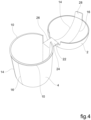
- the two half-shells 2 and 4 form a body in one piece (integral body), being hinged therebetween by a tab 22 ( Fig. 4 ) which forms part of the opening member 12; the tab 22 is obtained during the step of molding the body into a single piece of the container, such that the edges 22 and 26 thereof are per se separated from the wall of the half-shells.
- the two half-shells are preferably permanently connected therebetween, so as to avoid the accidental opening of the container and also so that the consumer is induced to open the container by acting upon the opening member rather than, possibly, by removing the half-shell acting as a lid or by tilting it.
- connection may be implemented by welding together wall portions of the two half-shells which, in the closed configuration, are superimposed and in contact.
- the welding may be carried out by gluing, for example using a natural or synthetic glue or by applying a heat-seal lacquer in the contact regions and subsequent heating, or any other known welding methodology (for example, ultrasonic, thermal, etc.)
- the welding region may be limited to the contact surface of the flange 10 of one of the half-shells with the inner surface of the other half-shell.
- each part 30 and 32 is formed from portions of the half-shells 2 and 4 that, as indicated above, have preferably been connected therebetween by welding or gluing; in the absence of a connection, it is understood that the two portions of the half-shell forming the parts 30 and 32 are separated from one another.
- the removal of the opening member 12 thus allows the container to open thereby facilitating the extraction of the contents.
- the container in the closed configuration thereof, has a minimum size of between 20 and 200 mm; this "minimum size" in the case of a container with a circular mouth profile is to be understood to be referring to the mouth diameter.
- the container, subject matter of the invention is a rigid-walled container with such rigidity as to provide adequate protection of the contents.
- the rigidity of the container is at least such that it maintains the features thereof of shape and volume when placed upon a support surface.
- the wall rigidity adapted to achieve adequate overall rigidity varies depending on the dimensions of the container; although the wall of the container is to be considered limitedly flexible, in the sense that it is not susceptible to breakage when subjected to bending by hand or mechanically, it has compression resistance and therefore a rigidity such that the container may be expediently used as a viable alternative to conventional containers for surprises and the like made of a plastics material, such as polypropylene and the copolymers thereof.
- the container may have a corrugated wall.
- Fig. 8 relating to a container, of the type shown in Fig. 1 , wherein the wall has a side wall provided with a plurality of corrugations 36, with a cross section, i.e. parallel to the mouth plane, that is notched.
- the outer wall of the container may be provided with a plurality of ribs or ribbings 36, projecting radially outwards and preferably with an extension orthogonal to the mouth plane.
- Such corrugations, ribs or ribbings may affect the entire wall of the container, with the possible exclusion of the wall region 15 defining the opening member or possibly only the tubular region of the container, previously referred to as the shell 4a.
- the weakening lines which may be obtained during the container forming step, have a reduced thickness with respect to the wall adjacent thereto, with a percentage reduction preferably on the order of 10-80%.
- weakening lines with a maximum thickness of about 100 microns may be used.
- Fig. 5 shows an embodiment wherein the container 1 comprises a first and a second half-shell, 40 and 42, both cup-shaped, which are connected by film hinges to a tubular wall portion 44 (in the cylindrical example) of the container.
- One or both half-shells may have the function of a lid.
- This container may also be made as a single-piece body, obtainable for example from a blank, wherein the formation thereof is shown in Fig. 6 and 7 ; the connection between the two cup-shaped half-shells and the tubular wall is made at the wall region defining the tear band, according to the hinge lines 46 and 48.
- the tubular wall 44 shown in a flat formation in Fig. 6 , has side flaps 50 that are welded or glued to the end portions of the two half-shells adjacent to the mouth; moreover, said wall has a side edge region 52, which is welded or glued to the opposite edge 54 in order to hold said wall in a tubular configuration.
- both cup-shaped half-shells 40 and 42 are connected to the tubular wall by welding or gluing, as previously indicated.
- the container, subject matter of the invention may be obtained by conventional processes of forming cellulose articles using the wet-forming technique or the most recent forming technique that uses a dry-formed cellulose blank.
- a cellulose pulp in water is used by immersing a suction forming mold into a liquid or semi-liquid pulp suspension and then applying suction in order to form the body of the container following the deposition of the fibers onto the walls of the mold.
- This technique requires a subsequent stage of drying the shaped product.
- the blank is inserted into a forming mold and subjected to high pressure and/or temperature.
- Fig. 9(a) shows, by way of example, a mold 56 and a complementary counter-mold 58 for making a container according to the invention, which conforms to the one shown in Fig. 1 to 4 .
- the cavity of the mold 56 substantially corresponds to the configuration of the container shown in Fig. 4 .
- the operational molding steps provide for the introduction of a blank of cellulose fibers 60 in the interposition position between the mold and the counter-mold ( Fig. 9(b) ) and the relative motion between the mold and the counter-mold to compress the blank inside the cavities of the mold 56 ( Fig. 9(c) ).
- the surprise or similar accessory is introduced into the container followed by the optional welding or gluing of the two half-shells.
- the invention also relates to a foodstuff package comprising a container as described above, including an amusement article or a foodstuff; such a package may, for example, be a chocolate egg.
- the container, subject matter of the invention is compostable and/or (bio)degradable and/or recyclable and has mechanical features such that it may thus be used as a viable eco-sustainable alternative to traditional containers for surprises and the like, obtained by the molding of plastics materials.
Landscapes
- Engineering & Computer Science (AREA)
- Mechanical Engineering (AREA)
- Life Sciences & Earth Sciences (AREA)
- Wood Science & Technology (AREA)
- Containers Having Bodies Formed In One Piece (AREA)
- Closures For Containers (AREA)
- Packages (AREA)
- Wrappers (AREA)
Abstract
Description
- The present invention relates to a container particularly intended for use as a container for gifts or surprise articles, such as toys or confectionery products, and intended to be introduced into the hollow body of a foodstuff material, such as a chocolate egg, or into a package comprising a foodstuff material.
- In particular, the invention relates to a container of the type comprising two half-shells, each having a containment wall and an open mouth, which are capable of being coupled mouth-to-mouth to form a closed container.
-
WO2007/074355 describes a container of the aforementioned type consisting of two half-shells of a plastics material, connected therebetween, so as to form a body in one piece by means of a joint that allows the movement of one of the two half-shells with respect to the other between a closed position of the container and an open position; the container has, on one or both half-shells, weakening lines adjacent to the joint which, following stresses applied to the container, are able to rupture before the joint is ruptured. The object of this configuration is to avoid separation of the two half-shells following manipulation by the user. In effect, following the possible rupture of the weakening lines, the two half-shells remain connected therebetween by means of one or two tabs extending from the joint. - One object of the invention is to provide a configuration, for a container of the type mentioned above, that is particularly suitable for making a container out of paper material and therefore compostable and/or (bio)degradable and/or recyclable.
- Another object of the invention is to provide a container made out of a paper material with an easy opening and which also maintains the features of mechanical properties, in particular a rigidity adapted to protect the products contained therein, which characterize typical containers made of a plastics material.
- In view of the aforementioned objects, the subject matter of the invention is a container having the features mentioned in the following claims.
- According to a characterizing aspect of the invention, the container is made of a material comprising or composed essentially of cellulose fibers; the material may comprise optional additives of the type conventionally used in the production of paper and cardboard; the material may also comprise any additives used to achieve gas and liquid barrier effects.
- According to another characterizing aspect, the body of the container comprises, in the closed configuration thereof, a tear-band opening member extending along the entire perimeter contour of the body of the container lying in a plane substantially orthogonal to the plane of the mouth contour of the half-shells.
- In a preferred embodiment, the tear-band opening member comprises a wall region of the first and second half-shells delimited by weakening lines which, in one embodiment, may be continuous lines or in sections with a reduced wall thickness (in relation to the adjacent wall thickness) or pre-scored.
- In a preferred embodiment, the first and second half-shells are connected therebetween so as to form a body in one piece, the connection being obtainable by means of a segment of the opening member.
- Further features and advantages of the container according to the invention will become evident from the following detailed description, made with reference to the accompanying drawings, provided by way of non-limiting example.
- In the accompanying drawings:
-
Fig. 1 is a sectional view of a container according to the invention; -
Fig. 2 is a perspective view of the container inFig. 1 , in a configuration in which the tear-band opening member has been partially removed; -
Fig. 3 is a perspective view showing the parts of the container following the removal of the opening member; -
Fig. 4 is a perspective view of the container in a resulting configuration following the forming thereof; -
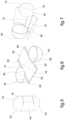
Fig. 5 is a perspective view of a second embodiment of the container; -
Fig. 6 and 7 are perspective views showing the formations from which the container inFig. 5 is obtained; -
Fig. 8 is a perspective view of a third embodiment of the container, adapted to increase wall rigidity, and -
Fig. 9(a), 9(b) and 9(c) are perspective views illustrating the operating sequence of molding with a mold and counter-mold of a container of the type inFig. 1 . - With reference to the drawings, a container according to the invention, indicated in the entirety thereof with 1, comprises a first and a second half-
shell - The term, used in this description, relating to the use of a material "comprising" cellulose or cellulose fibers or "composed essentially of cellulose or cellulose fibers" does not exclude the presence of optional additives, for example of the type conventionally used in the production of paper, or of additives used to obtain gas and liquid barrier effects or to improve mechanical properties. For example, such terms include the case wherein the material comprises from 70 to 99.9% by weight of cellulose fibers on an anhydrous basis, preferably from 90 to 99.9% by weight and from 0.1 to 30% by weight on an anhydrous basis of additives, preferably from 0.1 to 10% by weight.
- Possible additives may include starches, alkyl ketene dimer and inert fillers.
- Recycled cellulose fibers, preferably totally MOSH- and MOAH-free, may be used.
- In the embodiment shown in
Fig. 1 to 4 , the container comprises a cup-shaped half shell 2, optionally with a flattened top, with a lid function and ahalf shell 4, having a greater depth than thehalf shell 2, having a containment function, wherein the wall thereof comprises abottom region 4b, cup-shaped, optionally with a flattened top, and a cylindrical or slightly flared tubularshell wall region 4a. Optionally, the half-shell 2 may also have a shell-shaped tubular wall portion. - In the embodiment example, the two half-shells have a mouth, respectively 6 and 8, with a circular contour; it is however understood that the construction principle of the invention may also be applied to half-shells having a different mouth contour, for example elliptical, polygonal, ovoid or mixtilinear.
- The construction principle of the invention is also applicable to containers with a general ovoid shape wherein the two half-shells have a circular mouth contour, namely an ovoid mouth contour.
- In general, one of the half-shells has a greater depth and a containment function, while the other half-shell, with a shallower depth, has a lid function.
- Preferably, the two half-shells may be coupled mouth-to-mouth, for example in a front coupling relationship by inserting an end wall portion of one half-shell into the end wall portion of the other half-shell.
- In the example shown, the half-
shell 4 with a containment function is inserted into themouth 8 of the half-shell 2, whereby the end portions of the two half-shells, adjacent to the mouth, partially overlap. - Preferably, for the reasons more fully illustrated below, the half-shell inserted into the mouth of the other has, adjacent to the mouth thereof, a
radial flange 10 extending along the entire mouth contour or possibly limited to a circumferential mouth section. - According to a feature of the invention, the container comprises a tear-band opening
member 12 formed by awall region 15 of the container, which extends along the entire perimeter contour of the body of the container lying in a plane that is preferably substantially orthogonal to the plane of the mouth contour of the half-shells. Such opening member is defined by weakeninglines portion 18 of the mouth edge of one of the half-shells, in this case from the half-shell 2 acting as a lid, through the cup-shaped wall of said half-shell and then through thecontainment wall shell 4, to aportion 20 of the mouth edge of said other half-shell. - The aforementioned
radial flange 10, or radial flange section, creates a guide for removing the opening member. Optionally, the guide for removing the opening member may be represented by atab 28 protruding from the half-shell 2 at thesection 18 of the mouth outline wherefrom the tear-band openingmember 12 extends. - In the preferred embodiment, the two half-
shells Fig. 4 ) which forms part of theopening member 12; thetab 22 is obtained during the step of molding the body into a single piece of the container, such that theedges - In the closed configuration of the container and, therefore, following the insertion of the contents thereinto, the two half-shells are preferably permanently connected therebetween, so as to avoid the accidental opening of the container and also so that the consumer is induced to open the container by acting upon the opening member rather than, possibly, by removing the half-shell acting as a lid or by tilting it.
- The connection may be implemented by welding together wall portions of the two half-shells which, in the closed configuration, are superimposed and in contact.
- The welding may be carried out by gluing, for example using a natural or synthetic glue or by applying a heat-seal lacquer in the contact regions and subsequent heating, or any other known welding methodology (for example, ultrasonic, thermal, etc.) The welding region may be limited to the contact surface of the
flange 10 of one of the half-shells with the inner surface of the other half-shell. - Following the total removal of the
opening member 12, the body of the container is divided into twoparts part shells parts - The removal of the
opening member 12 thus allows the container to open thereby facilitating the extraction of the contents. - In a preferred embodiment, the container, in the closed configuration thereof, has a minimum size of between 20 and 200 mm; this "minimum size" in the case of a container with a circular mouth profile is to be understood to be referring to the mouth diameter.
- The container, subject matter of the invention, is a rigid-walled container with such rigidity as to provide adequate protection of the contents.
- The rigidity of the container is at least such that it maintains the features thereof of shape and volume when placed upon a support surface. The wall rigidity adapted to achieve adequate overall rigidity varies depending on the dimensions of the container; although the wall of the container is to be considered limitedly flexible, in the sense that it is not susceptible to breakage when subjected to bending by hand or mechanically, it has compression resistance and therefore a rigidity such that the container may be expediently used as a viable alternative to conventional containers for surprises and the like made of a plastics material, such as polypropylene and the copolymers thereof.
- Optionally, in order to increase wall rigidity, the container may have a corrugated wall. This embodiment is shown in
Fig. 8 , relating to a container, of the type shown inFig. 1 , wherein the wall has a side wall provided with a plurality ofcorrugations 36, with a cross section, i.e. parallel to the mouth plane, that is notched. Alternatively, the outer wall of the container may be provided with a plurality of ribs orribbings 36, projecting radially outwards and preferably with an extension orthogonal to the mouth plane. Such corrugations, ribs or ribbings may affect the entire wall of the container, with the possible exclusion of thewall region 15 defining the opening member or possibly only the tubular region of the container, previously referred to as theshell 4a. - The weakening lines, which may be obtained during the container forming step, have a reduced thickness with respect to the wall adjacent thereto, with a percentage reduction preferably on the order of 10-80%.
- For example, for a container with a wall of 200 microns, weakening lines with a maximum thickness of about 100 microns may be used.
-
Fig. 5 shows an embodiment wherein thecontainer 1 comprises a first and a second half-shell, 40 and 42, both cup-shaped, which are connected by film hinges to a tubular wall portion 44 (in the cylindrical example) of the container. One or both half-shells may have the function of a lid. - This container may also be made as a single-piece body, obtainable for example from a blank, wherein the formation thereof is shown in
Fig. 6 and 7 ; the connection between the two cup-shaped half-shells and the tubular wall is made at the wall region defining the tear band, according to thehinge lines tubular wall 44, shown in a flat formation inFig. 6 , hasside flaps 50 that are welded or glued to the end portions of the two half-shells adjacent to the mouth; moreover, said wall has aside edge region 52, which is welded or glued to theopposite edge 54 in order to hold said wall in a tubular configuration. - In the closed configuration of the container according to this embodiment, preferably both cup-shaped half-
shells - The container, subject matter of the invention, may be obtained by conventional processes of forming cellulose articles using the wet-forming technique or the most recent forming technique that uses a dry-formed cellulose blank.
- In the wet-forming process, a cellulose pulp in water is used by immersing a suction forming mold into a liquid or semi-liquid pulp suspension and then applying suction in order to form the body of the container following the deposition of the fibers onto the walls of the mold.
- This technique requires a subsequent stage of drying the shaped product.
- In the most recent forming technique using a dry-formed, cellulose fiber blank, the blank is inserted into a forming mold and subjected to high pressure and/or temperature.
-
Fig. 9(a) shows, by way of example, amold 56 and a complementary counter-mold 58 for making a container according to the invention, which conforms to the one shown inFig. 1 to 4 . The cavity of themold 56 substantially corresponds to the configuration of the container shown inFig. 4 . The operational molding steps provide for the introduction of a blank ofcellulose fibers 60 in the interposition position between the mold and the counter-mold (Fig. 9(b) ) and the relative motion between the mold and the counter-mold to compress the blank inside the cavities of the mold 56 (Fig. 9(c) ). - After forming, and possibly drying, if necessary in view of the method adopted, the surprise or similar accessory is introduced into the container followed by the optional welding or gluing of the two half-shells.
- The invention also relates to a foodstuff package comprising a container as described above, including an amusement article or a foodstuff; such a package may, for example, be a chocolate egg.
- Due to the use of a cellulose material, the container, subject matter of the invention, is compostable and/or (bio)degradable and/or recyclable and has mechanical features such that it may thus be used as a viable eco-sustainable alternative to traditional containers for surprises and the like, obtained by the molding of plastics materials.
Claims (11)
- A container for products, particularly amusement articles or foodstuffs, comprising at least a first and a second half-shell (2, 4) each having a mouth contour (6, 8) and a retaining wall, capable of being coupled mouth-to-mouth to form a container in a closed configuration, characterized in that the container is formed from a material comprising cellulose fibers and optional additives, and comprises an opening member (12) of the container configured as a tear-band extending along the entire perimeter contour of the container lying in a plane substantially orthogonal to the plane of the mouth contour of said half-shells and wherein said first and second half-shells (2, 4) form a body in one piece, being connected therebetween by means of a tab (22) that constitutes part of the opening member.
- Container according to claim 1, characterized in that said tear-band opening member (12) comprises a wall region (15) of the first and second half-shells (2, 4) delimited by weakening lines (14, 16).
- Container according to claim 2, characterized in that said weakening lines (14, 16) are lines with a reduced wall thickness or are partially pre-scored, either continuously or in sections.
- Container according to any one of claims 1 to 3, characterized in that said tear-band opening member (12) comprises a continuous region (15) of the container wall extending from a section (18) of the mouth contour of one of the half-shells to a section (20) of the mouth contour of the other half-shell adjacent to said first section.
- Container according to any one of claims 1 to 4, characterized in that one of said half-shells (2) is configured as a lid and the other half-shell (4) is configured with a containment function, wherein the half-shell configured as a lid is superimposed on an end region of the other half-shell adjacent its mouth.
- Container according to any one of the preceding claims having rigid walls, with a rigidity at least such that the container retains the shape and volume features thereof when placed on a supporting surface.
- Container according to any one of the preceding claims, characterized in that, in the closed configuration of the container, said first and second half-shells are connected therebetween by means of welding or gluing along overlapping portions of the wall adjacent to the mouth.
- Container according to any one of the preceding claims, characterized in that the wall of the container has a plurality of ribs or ribbings (36) adapted to increase the rigidity of the container.
- Container according to any one of the preceding claims, characterized in that said weakening lines have a thickness reduced by 10 to 80% compared to the wall thickness of the container adjacent thereto.
- Container according to any one of the preceding claims characterized in that it is obtained from a cellulose fiber material comprising from 70 to 99.9% by weight of cellulose fibers on an anhydrous basis and from 0.1 to 30% by weight of additives conventionally used in paper making or capable of achieving gas and/or liquid barrier effects and/or increasing mechanical properties.
- Foodstuff packaging comprising a container according to any one of the preceding claims wherein an amusement article or a foodstuff is included.
Applications Claiming Priority (1)
| Application Number | Priority Date | Filing Date | Title |
|---|---|---|---|
| IT202300010089 | 2023-05-18 |
Publications (2)
| Publication Number | Publication Date |
|---|---|
| EP4464616A1 true EP4464616A1 (en) | 2024-11-20 |
| EP4464616B1 EP4464616B1 (en) | 2026-02-25 |
Family
ID=87418658
Family Applications (1)
| Application Number | Title | Priority Date | Filing Date |
|---|---|---|---|
| EP24176190.7A Active EP4464616B1 (en) | 2023-05-18 | 2024-05-16 | Container for surprises |
Country Status (8)
| Country | Link |
|---|---|
| US (1) | US20240383636A1 (en) |
| EP (1) | EP4464616B1 (en) |
| CN (1) | CN118992287A (en) |
| AR (1) | AR132718A1 (en) |
| AU (1) | AU2024203153A1 (en) |
| CA (1) | CA3238149A1 (en) |
| MX (1) | MX2024006014A (en) |
| PL (1) | PL4464616T3 (en) |
Citations (5)
| Publication number | Priority date | Publication date | Assignee | Title |
|---|---|---|---|---|
| FR822546A (en) * | 1936-06-04 | 1937-12-31 | Plastic packaging | |
| WO2002090209A1 (en) * | 2001-05-07 | 2002-11-14 | Australian Postal Corporation | Packaging system |
| WO2007074355A1 (en) | 2005-11-16 | 2007-07-05 | Magic Production Group (M.P.G.) Sa | Surprise container |
| US20160001918A1 (en) * | 2014-07-03 | 2016-01-07 | Performance Designed Products Llc | Container with separable components |
| RU2636300C1 (en) * | 2016-09-23 | 2017-11-21 | Елена Геннадьевна Баталина | Box for food products |
-
2024
- 2024-05-13 CA CA3238149A patent/CA3238149A1/en active Pending
- 2024-05-13 AU AU2024203153A patent/AU2024203153A1/en active Pending
- 2024-05-16 EP EP24176190.7A patent/EP4464616B1/en active Active
- 2024-05-16 US US18/666,276 patent/US20240383636A1/en active Pending
- 2024-05-16 MX MX2024006014A patent/MX2024006014A/en unknown
- 2024-05-16 PL PL24176190.7T patent/PL4464616T3/en unknown
- 2024-05-17 CN CN202410612830.3A patent/CN118992287A/en active Pending
- 2024-05-17 AR ARP240101260A patent/AR132718A1/en unknown
Patent Citations (5)
| Publication number | Priority date | Publication date | Assignee | Title |
|---|---|---|---|---|
| FR822546A (en) * | 1936-06-04 | 1937-12-31 | Plastic packaging | |
| WO2002090209A1 (en) * | 2001-05-07 | 2002-11-14 | Australian Postal Corporation | Packaging system |
| WO2007074355A1 (en) | 2005-11-16 | 2007-07-05 | Magic Production Group (M.P.G.) Sa | Surprise container |
| US20160001918A1 (en) * | 2014-07-03 | 2016-01-07 | Performance Designed Products Llc | Container with separable components |
| RU2636300C1 (en) * | 2016-09-23 | 2017-11-21 | Елена Геннадьевна Баталина | Box for food products |
Also Published As
| Publication number | Publication date |
|---|---|
| AR132718A1 (en) | 2025-07-23 |
| US20240383636A1 (en) | 2024-11-21 |
| MX2024006014A (en) | 2024-12-06 |
| CN118992287A (en) | 2024-11-22 |
| EP4464616B1 (en) | 2026-02-25 |
| CA3238149A1 (en) | 2025-10-30 |
| PL4464616T3 (en) | 2026-06-01 |
| AU2024203153A1 (en) | 2024-12-05 |
Similar Documents
| Publication | Publication Date | Title |
|---|---|---|
| FI128578B (en) | Stackable product package and method for producing the same and blank for a product package | |
| JP3241701U (en) | product packaging container | |
| US4925035A (en) | Packaging for food and method of producing same | |
| CA2565920C (en) | Container for surprise gifts produced in one piece | |
| JP2020512242A5 (en) | ||
| DK3126259T3 (en) | CONTAINS COMPREHENSIVE EXTERNAL PAPER SHELL | |
| EP0854092A2 (en) | Container of thermofarmable and heat sealable material | |
| AU2011294801B2 (en) | Method for forming a package, a package and a package blank | |
| CN100586319C (en) | Rigid packets for tobacco products having hinged lids and related blanks | |
| EP3749586B1 (en) | Sealing arrangement for packaging container | |
| CN114929465B (en) | Packaging container comprising a container body and a base plate | |
| CN116529057B (en) | Composite paperboard containers for bulk solids and their manufacturing method | |
| MXPA05003794A (en) | An opening arrangement, a package, as well as a method of providing a package with an opening arrangement. | |
| WO2017158239A1 (en) | Product package and a method for producing the package | |
| EP4464616B1 (en) | Container for surprises | |
| US12479183B2 (en) | Packaging container and a method of producing such a packaging container | |
| US5083702A (en) | Gable-top container and method and apparatus for construction thereof | |
| US20230182968A1 (en) | Folding Lid For Covering A Container Opening Made From A Recyclable Material And Arrangement And Method For Packaging An Item | |
| JP3605434B2 (en) | Semi-solid paper container | |
| NO173598B (en) | THERMOPLASTIC COATED FLAT CARTRIDGE CARTON CONTAINER | |
| US20260091907A1 (en) | Blank for packaging a food portion and method for packaging a food portion | |
| US3964671A (en) | Carton for a package convertible to a baking pan | |
| BR102024010010A2 (en) | CONTAINER FOR FOOD PRODUCTS AND PACKAGING | |
| RU62898U1 (en) | ROUND CARTONBOARD BOX FOR FOOD | |
| GB2316937A (en) | A container |
Legal Events
| Date | Code | Title | Description |
|---|---|---|---|
| PUAI | Public reference made under article 153(3) epc to a published international application that has entered the european phase |
Free format text: ORIGINAL CODE: 0009012 |
|
| STAA | Information on the status of an ep patent application or granted ep patent |
Free format text: STATUS: THE APPLICATION HAS BEEN PUBLISHED |
|
| AK | Designated contracting states |
Kind code of ref document: A1 Designated state(s): AL AT BE BG CH CY CZ DE DK EE ES FI FR GB GR HR HU IE IS IT LI LT LU LV MC ME MK MT NL NO PL PT RO RS SE SI SK SM TR |
|
| STAA | Information on the status of an ep patent application or granted ep patent |
Free format text: STATUS: REQUEST FOR EXAMINATION WAS MADE |
|
| 17P | Request for examination filed |
Effective date: 20250509 |
|
| GRAP | Despatch of communication of intention to grant a patent |
Free format text: ORIGINAL CODE: EPIDOSNIGR1 |
|
| STAA | Information on the status of an ep patent application or granted ep patent |
Free format text: STATUS: GRANT OF PATENT IS INTENDED |
|
| RIC1 | Information provided on ipc code assigned before grant |
Ipc: B65D 8/00 20060101AFI20250821BHEP Ipc: B65D 13/00 20060101ALI20250821BHEP Ipc: B65D 6/00 20060101ALI20250821BHEP Ipc: B65D 77/32 20060101ALI20250821BHEP Ipc: B65D 43/16 20060101ALI20250821BHEP |
|
| INTG | Intention to grant announced |
Effective date: 20250918 |
|
| P01 | Opt-out of the competence of the unified patent court (upc) registered |
Free format text: CASE NUMBER: UPC_APP_0010126_4464616/2025 Effective date: 20251017 |
|
| GRAS | Grant fee paid |
Free format text: ORIGINAL CODE: EPIDOSNIGR3 |
|
| GRAA | (expected) grant |
Free format text: ORIGINAL CODE: 0009210 |
|
| STAA | Information on the status of an ep patent application or granted ep patent |
Free format text: STATUS: THE PATENT HAS BEEN GRANTED |
|
| AK | Designated contracting states |
Kind code of ref document: B1 Designated state(s): AL AT BE BG CH CY CZ DE DK EE ES FI FR GB GR HR HU IE IS IT LI LT LU LV MC ME MK MT NL NO PL PT RO RS SE SI SK SM TR |
|
| REG | Reference to a national code |
Ref country code: CH Ref legal event code: F10 Free format text: ST27 STATUS EVENT CODE: U-0-0-F10-F00 (AS PROVIDED BY THE NATIONAL OFFICE) Effective date: 20260225 Ref country code: GB Ref legal event code: FG4D |
|
| REG | Reference to a national code |
Ref country code: DE Ref legal event code: R096 Ref document number: 602024002751 Country of ref document: DE |
|
| REG | Reference to a national code |
Ref country code: IE Ref legal event code: FG4D |
|
| REG | Reference to a national code |
Ref country code: NL Ref legal event code: MP Effective date: 20260225 |
|
| PG25 | Lapsed in a contracting state [announced via postgrant information from national office to epo] |
Ref country code: RS Free format text: LAPSE BECAUSE OF FAILURE TO SUBMIT A TRANSLATION OF THE DESCRIPTION OR TO PAY THE FEE WITHIN THE PRESCRIBED TIME-LIMIT Effective date: 20260525 |
|
| PG25 | Lapsed in a contracting state [announced via postgrant information from national office to epo] |
Ref country code: ES Free format text: LAPSE BECAUSE OF FAILURE TO SUBMIT A TRANSLATION OF THE DESCRIPTION OR TO PAY THE FEE WITHIN THE PRESCRIBED TIME-LIMIT Effective date: 20260225 |
|
| PGFP | Annual fee paid to national office [announced via postgrant information from national office to epo] |
Ref country code: PL Payment date: 20260428 Year of fee payment: 3 |
|
| PG25 | Lapsed in a contracting state [announced via postgrant information from national office to epo] |
Ref country code: GR Free format text: LAPSE BECAUSE OF FAILURE TO SUBMIT A TRANSLATION OF THE DESCRIPTION OR TO PAY THE FEE WITHIN THE PRESCRIBED TIME-LIMIT Effective date: 20260526 |
|
| PGFP | Annual fee paid to national office [announced via postgrant information from national office to epo] |
Ref country code: IT Payment date: 20260601 Year of fee payment: 3 |
|
| REG | Reference to a national code |
Ref country code: LT Ref legal event code: MG9D |
|
| PG25 | Lapsed in a contracting state [announced via postgrant information from national office to epo] |
Ref country code: LT Free format text: LAPSE BECAUSE OF FAILURE TO SUBMIT A TRANSLATION OF THE DESCRIPTION OR TO PAY THE FEE WITHIN THE PRESCRIBED TIME-LIMIT Effective date: 20260225 |
|
| PGFP | Annual fee paid to national office [announced via postgrant information from national office to epo] |
Ref country code: DE Payment date: 20260521 Year of fee payment: 3 |
|
| PG25 | Lapsed in a contracting state [announced via postgrant information from national office to epo] |
Ref country code: NO Free format text: LAPSE BECAUSE OF FAILURE TO SUBMIT A TRANSLATION OF THE DESCRIPTION OR TO PAY THE FEE WITHIN THE PRESCRIBED TIME-LIMIT Effective date: 20260525 |
|
| PG25 | Lapsed in a contracting state [announced via postgrant information from national office to epo] |
Ref country code: SE Free format text: LAPSE BECAUSE OF FAILURE TO SUBMIT A TRANSLATION OF THE DESCRIPTION OR TO PAY THE FEE WITHIN THE PRESCRIBED TIME-LIMIT Effective date: 20260225 Ref country code: AT Free format text: LAPSE BECAUSE OF FAILURE TO SUBMIT A TRANSLATION OF THE DESCRIPTION OR TO PAY THE FEE WITHIN THE PRESCRIBED TIME-LIMIT Effective date: 20260225 Ref country code: FI Free format text: LAPSE BECAUSE OF FAILURE TO SUBMIT A TRANSLATION OF THE DESCRIPTION OR TO PAY THE FEE WITHIN THE PRESCRIBED TIME-LIMIT Effective date: 20260225 |
|
| REG | Reference to a national code |
Ref country code: AT Ref legal event code: MK05 Ref document number: 1890636 Country of ref document: AT Kind code of ref document: T Effective date: 20260225 |
|
| PGFP | Annual fee paid to national office [announced via postgrant information from national office to epo] |
Ref country code: BE Payment date: 20260520 Year of fee payment: 3 |
|
| PG25 | Lapsed in a contracting state [announced via postgrant information from national office to epo] |
Ref country code: HR Free format text: LAPSE BECAUSE OF FAILURE TO SUBMIT A TRANSLATION OF THE DESCRIPTION OR TO PAY THE FEE WITHIN THE PRESCRIBED TIME-LIMIT Effective date: 20260225 |
|
| PG25 | Lapsed in a contracting state [announced via postgrant information from national office to epo] |
Ref country code: IS Free format text: LAPSE BECAUSE OF FAILURE TO SUBMIT A TRANSLATION OF THE DESCRIPTION OR TO PAY THE FEE WITHIN THE PRESCRIBED TIME-LIMIT Effective date: 20260625 Ref country code: PT Free format text: LAPSE BECAUSE OF FAILURE TO SUBMIT A TRANSLATION OF THE DESCRIPTION OR TO PAY THE FEE WITHIN THE PRESCRIBED TIME-LIMIT Effective date: 20260625 |
|
| PG25 | Lapsed in a contracting state [announced via postgrant information from national office to epo] |
Ref country code: NL Free format text: LAPSE BECAUSE OF FAILURE TO SUBMIT A TRANSLATION OF THE DESCRIPTION OR TO PAY THE FEE WITHIN THE PRESCRIBED TIME-LIMIT Effective date: 20260225 |
|
| PGFP | Annual fee paid to national office [announced via postgrant information from national office to epo] |
Ref country code: TR Payment date: 20260501 Year of fee payment: 3 |
|
| PGFP | Annual fee paid to national office [announced via postgrant information from national office to epo] |
Ref country code: FR Payment date: 20260430 Year of fee payment: 3 |
|
| PG25 | Lapsed in a contracting state [announced via postgrant information from national office to epo] |
Ref country code: LV Free format text: LAPSE BECAUSE OF FAILURE TO SUBMIT A TRANSLATION OF THE DESCRIPTION OR TO PAY THE FEE WITHIN THE PRESCRIBED TIME-LIMIT Effective date: 20260225 |
|
| PG25 | Lapsed in a contracting state [announced via postgrant information from national office to epo] |
Ref country code: BG Free format text: LAPSE BECAUSE OF FAILURE TO SUBMIT A TRANSLATION OF THE DESCRIPTION OR TO PAY THE FEE WITHIN THE PRESCRIBED TIME-LIMIT Effective date: 20260225 |