EP4464603A1 - Systems and methods for a smart navigation tuning panel - Google Patents
Systems and methods for a smart navigation tuning panel Download PDFInfo
- Publication number
- EP4464603A1 EP4464603A1 EP24165102.5A EP24165102A EP4464603A1 EP 4464603 A1 EP4464603 A1 EP 4464603A1 EP 24165102 A EP24165102 A EP 24165102A EP 4464603 A1 EP4464603 A1 EP 4464603A1
- Authority
- EP
- European Patent Office
- Prior art keywords
- aircraft
- memory
- line
- replaceable unit
- target data
- Prior art date
- Legal status (The legal status is an assumption and is not a legal conclusion. Google has not performed a legal analysis and makes no representation as to the accuracy of the status listed.)
- Pending
Links
Images



Classifications
-
- B—PERFORMING OPERATIONS; TRANSPORTING
- B64—AIRCRAFT; AVIATION; COSMONAUTICS
- B64D—EQUIPMENT FOR FITTING IN OR TO AIRCRAFT; FLIGHT SUITS; PARACHUTES; ARRANGEMENT OR MOUNTING OF POWER PLANTS OR PROPULSION TRANSMISSIONS IN AIRCRAFT
- B64D43/00—Arrangements or adaptations of instruments
-
- G—PHYSICS
- G06—COMPUTING OR CALCULATING; COUNTING
- G06F—ELECTRIC DIGITAL DATA PROCESSING
- G06F13/00—Interconnection of, or transfer of information or other signals between, memories, input/output devices or central processing units
- G06F13/14—Handling requests for interconnection or transfer
- G06F13/36—Handling requests for interconnection or transfer for access to common bus or bus system
-
- G—PHYSICS
- G05—CONTROLLING; REGULATING
- G05B—CONTROL OR REGULATING SYSTEMS IN GENERAL; FUNCTIONAL ELEMENTS OF SUCH SYSTEMS; MONITORING OR TESTING ARRANGEMENTS FOR SUCH SYSTEMS OR ELEMENTS
- G05B19/00—Program-control systems
- G05B19/02—Program-control systems electric
- G05B19/04—Program control other than numerical control, i.e. in sequence controllers or logic controllers
- G05B19/042—Program control other than numerical control, i.e. in sequence controllers or logic controllers using digital processors
- G05B19/0421—Multiprocessor system
-
- G—PHYSICS
- G01—MEASURING; TESTING
- G01C—MEASURING DISTANCES, LEVELS OR BEARINGS; SURVEYING; NAVIGATION; GYROSCOPIC INSTRUMENTS; PHOTOGRAMMETRY OR VIDEOGRAMMETRY
- G01C23/00—Combined instruments indicating more than one navigational value, e.g. for aircraft; Combined measuring devices for measuring two or more variables of movement, e.g. distance, speed or acceleration
- G01C23/005—Flight directors
-
- G—PHYSICS
- G08—SIGNALLING
- G08G—TRAFFIC CONTROL SYSTEMS
- G08G5/00—Traffic control systems for aircraft
- G08G5/20—Arrangements for acquiring, generating, sharing or displaying traffic information
- G08G5/21—Arrangements for acquiring, generating, sharing or displaying traffic information located onboard the aircraft
-
- G—PHYSICS
- G08—SIGNALLING
- G08G—TRAFFIC CONTROL SYSTEMS
- G08G5/00—Traffic control systems for aircraft
- G08G5/20—Arrangements for acquiring, generating, sharing or displaying traffic information
- G08G5/26—Transmission of traffic-related information between aircraft and ground stations
-
- G—PHYSICS
- G08—SIGNALLING
- G08G—TRAFFIC CONTROL SYSTEMS
- G08G5/00—Traffic control systems for aircraft
- G08G5/50—Navigation or guidance aids
- G08G5/54—Navigation or guidance aids for approach or landing
-
- G—PHYSICS
- G05—CONTROLLING; REGULATING
- G05B—CONTROL OR REGULATING SYSTEMS IN GENERAL; FUNCTIONAL ELEMENTS OF SUCH SYSTEMS; MONITORING OR TESTING ARRANGEMENTS FOR SUCH SYSTEMS OR ELEMENTS
- G05B2219/00—Program-control systems
- G05B2219/20—Pc systems
- G05B2219/24—Pc safety
- G05B2219/24182—Redundancy
-
- G—PHYSICS
- G06—COMPUTING OR CALCULATING; COUNTING
- G06F—ELECTRIC DIGITAL DATA PROCESSING
- G06F2213/00—Indexing scheme relating to interconnection of, or transfer of information or other signals between, memories, input/output devices or central processing units
- G06F2213/40—Bus coupling
Definitions
- the present disclosure is generally related to systems and methods for a smart navigation tuning panel.
- Legacy aircraft have well established operating procedures that many pilots have been trained on. Having a large pool of trained pilots can reduce operating costs and improve safety. Legacy aircraft may have design elements different than recently designed aircraft. For example, some legacy aircraft may require a pilot to manually enter an instrument landing system frequency that is displayed on a screen. Updating legacy designs may require altering operating procedures, which can be an expensive process and require re-training pilots in the new operating procedures, thereby reducing the pool of available pilots.
- a line-replaceable unit (LRU) for an aircraft includes an interface configured to couple to an aircraft data bus.
- the LRU further includes one or more processors coupled to the interface.
- the one or more processors are configured to monitor communications over the aircraft data bus between a pilot interface device and a second LRU.
- the LRU is distinct from the second LRU and is distinct from the pilot interface device.
- the one or more processors are further configured to, in response to detecting a particular page being transmitted over the aircraft data bus, extract target data associated with the particular page from the aircraft data bus.
- the one or more processors are further configured to store the target data at a memory associated with the one or more processors.
- a method includes monitoring, at one or more processors of a first line-replaceable unit (LRU), communications over an aircraft data bus between a pilot interface device and a second LRU.
- the first LRU is distinct from the second LRU and is distinct from the pilot interface device.
- the method further includes, in response to detecting a particular page being transmitted over the aircraft data bus, extracting target data associated with the particular page from the aircraft data bus.
- the method further includes storing the target data at a memory associated with the one or more processors.
- a computer-readable storage device stores instructions that are executable by one or more processors of a line-replaceable unit (LRU) to perform operations.
- the operations include monitoring communications over a data bus between an interface device and a second LRU.
- the first LRU is distinct from the second LRU and is distinct from the pilot interface device.
- the operations include, in response to detecting a particular page being transmitted over the data bus, extracting target data associated with the particular page from the data bus.
- the operations further include storing the target data at a memory.
- Flight procedures for some legacy aircraft require a pilot to read a radio frequency from a Control Display Unit (CDU) and enter the frequency into a navigation (NAV) tuning panel. This requires a pilot to read the CDU and manually enter the frequency. Once the frequency has been entered, the pilot must verify the frequency before making it the active frequency.
- Systems disclosed herein enable the NAV tuning panel to monitor communications between the CDU and a flight management computer (e.g., a message sent from the flight management computer to the CDU to display the radio frequency to the pilot).
- a navigation frequency can be extracted from the message and used to automatically update a standby frequency of the NAV tuning panel. The pilot can then verify the radio frequency before making it the active frequency.
- the disclosed systems simplify the process of tuning to navigation radio frequencies in a manner that reduces pilot workload and reduces the possibility of incorrect data entry.
- the pilot can save time and reduce errors by not needing to manually enter the frequency.
- the flight procedures do not need to be changed as they still require pilot verification and input.
- an ordinal term e.g., "first,” “second,” “third,” etc.
- an element such as a structure, a component, an operation, etc.
- the term “set” refers to a grouping of one or more elements
- the term “plurality” refers to multiple elements.
- the aircraft system includes an aircraft data bus 104.
- a flight management computer (FMC) 106 communicates with a control display unit (CDU) 108 by transmitting message(s) 116 along the aircraft data bus 104.
- the FMC 106 may include a navigation database that provides information about airports, routes, or a combination thereof.
- the FMC 106 may also be configured to identify an aircraft's current position, determine speeds for an autopilot, or a combination thereof.
- the CDU 108 may be configured to display pages of data provided by the FMC 106 via the message(s) 116.
- the CDU 108 may also include an input that enables a pilot to input data or send requests for specific data to the FMC 106 via the message(s) 116.
- the automated tuning panel 102, the FMC 106, and the CDU 108 may each be a line-replaceable unit (LRU).
- LRU line-replaceable unit
- the automated tuning panel 102 includes a monitoring interface 110 that is configured to couple the automated tuning panel 102 to the aircraft data bus 104.
- the monitoring interface 110 is configured to monitor the message(s) 116 transmitted along the aircraft data bus 104.
- the automated tuning panel 102 may correspond to a navigation (NAV) radio tuning panel.
- NAV navigation
- the automated tuning panel 102 When the automated tuning panel 102 detects a particular page in the message(s) 116 via the monitoring interface 110, the automated tuning panel 102 is configured to store target data from the particular page at a memory.
- the automated tuning panel may compare the target data to data already stored in the memory.
- the automated tuning panel may only store the target data into memory responsive to the target data being distinct from the data already stored in memory.
- the memory that the automated tuning panel 102 stores the target data in may be a standby memory like standby memory 212 of FIGs. 2A and 2B .
- the target data may include a particular radio frequency.
- the particular page may be an approach page labeled with the string "approach ref' and the target data may be an instrument landing system (ILS) frequency on the approach page.
- ILS instrument landing system
- the target data may be any frequency that can be processed by the automated tuning panel such as a ground-based augmentation landing system (GLS) frequency, a very high frequency omni-directional range (VOR) frequency, a distance measuring equipment (DME) frequency, or a microwave landing system (MLS) frequency.
- the particular page may be any page that includes a frequency that would be desired by a pilot.
- the automated tuning panel 102 may be configured to change the frequency stored in memory to a frequency not specifically identified in a second page.
- the monitoring interface 110 may detect that a second particular page is being transmitted via the message(s) 116.
- the second particular page may indicate that the aircraft is performing or subject to a required navigation performance (RNP) approach.
- RNP navigation performance
- an aircraft is expected to tune to a VOR frequency to receive proper navigation assistance.
- the automated tuning panel 102 may store a VOR frequency into the standby memory for pilot verification before tuning.
- the VOR frequency may be a predetermined VOR frequency stored in the memory or it may be a VOR frequency determined via random number generation or any other means of number generation.
- the automated tuning panel 102 may include inputs (e.g., the buttons illustrated in FIG. 1 ) that enable the pilot to enter a frequency into the standby memory. Additionally, the automated tuning panel may include a button that enables a pilot to swap a frequency stored in the standby memory with a frequency stored in an active memory. The active memory stores a frequency that a radio 112 is currently tuned to. Pressing the button to swap the two frequencies may result in a message being sent to an aircraft control system via the aircraft data bus 104. The aircraft control system may include the radio 112. Alternatively, the automated tuning panel may have a direct connection 114 with the radio 112, and the automated tuning panel 102 may transmit a message to the radio 112 via the direct connection. The standby frequency may not be transferred to the radio prior to the button being pressed.
- inputs e.g., the buttons illustrated in FIG. 1
- the automated tuning panel may include a button that enables a pilot to swap a frequency stored in the standby memory with a frequency stored in an active memory.
- the automated tuning panel system 200 may include an automated tuning panel 202.
- the automated tuning panel system 200 may further include one or more processors 206, the monitoring interface 110 of FIG. 1 , one or more user input device(s) 222 (including, for example, button 204 and/or one or more other buttons, knobs, switches, etc.), and a memory 210.
- the automated tuning panel system 200 is one example of automated tuning panel 102 as illustrated and described with reference to FIG. 1 .
- the automated tuning panel 202 includes a display 220 for an active frequency of the radio 112 of FIG. 1 and a display 208 for a standby frequency.
- a pilot can adjust the active frequency or the standby frequency using the user interface device(s) 222.
- the active frequency may be stored in an active memory 214 of the memory 210.
- the standby frequency may be stored in a standby memory 212 of the memory 210.
- the standby memory 212 and active memory 214 may be two locations in memory that are identified as either active or standby based on the value of a register.
- the active memory and standby memories may be two separate memory devices that are part of memory 210 or two different sections of a single memory device that is part of memory 210.
- the memory 210 may also store instructions configured to be executed by the one or more processors 206.
- the active frequency is shown to be 118.035 on display 220 and the standby frequency is shown to be 136.990 on the display 208. Accordingly, if the monitoring interface 110 detected a particular page, the one or more processors 206 would overwrite the 136.990 frequency with the target data.
- Swapping the frequencies may be achieved by overwriting the frequencies in their current locations in memory, writing the frequencies to new locations in memory and changing pointers to point to the new locations, changing pointers in memory, or changing a value of a flag that identifies which memory location is standby and which is active.
- FIG. 2B a diagram of the automated tuning panel system 200 is shown.
- the button 204 has been pressed. Accordingly, the frequency 118.035 has been moved from being the active frequency to the standby frequency and is presented via the display 220, and the frequency 136.990 has been moved from being the standby frequency to the active frequency and is presented via the display 208.
- the monitoring interface 110 detected a communication of relevant data over the aircraft data bus 104 (e.g., a page that included navigation radio data)
- the one or more processors 206 would overwrite the 118.035 frequency with the target data from the bus.
- FIG. 3 a diagram 300 of an approach reference page 306 being monitored by the monitoring interface 110 is shown.
- the page includes a specified string 302 and target data 304.
- the monitoring interface 110 of FIGs. 1 , 2A, and 2B may monitor the aircraft data bus 104 of FIG. 1 for a page containing the specified string 302.
- the specified string 302 is "approach ref.”
- the specified string could correspond to any string that appears on a page containing a desired frequency.
- the one or more processors 206 of FIGs. 2A and 2B may process the page to identify target data 304.
- the one or more processors 206 may search for content of a data field with a predetermined offset to the specified string 302.
- the one or more processors 206 may search for a specific string that occurs before the target data 304.
- the one or more processors may search for the string "Front CRS" that occurs before the target data 304. Any other search method may be used to identify the target data 304.
- FIG. 4 a particular illustrative example of a method is depicted and generally designated 400.
- operations of the method 400 are initiated, performed, or controlled by a processor, such as by one or more processors 206 of FIGs. 2A and 2B executing instructions.
- the method 400 includes monitoring, at block 402, at one or more processors of a first line-replaceable unit (LRU), communications over an aircraft data bus between a pilot interface device and a second LRU.
- LRU line-replaceable unit
- the automated tuning panel 102 of FIG. 1 or the automated tuning panel system 200 of FIGs. 2A and 2B may monitor the aircraft data bus 104 for the message(s) 116 between the FMC 106 and the CDU 108.
- the automated tuning panel 102 or the automated tuning panel system 200 may monitor for messages containing specific data, a specific header, a specific sending device, a specific recipient device, or any other message attributes that assists in identifying a particular message.
- the method 400 includes, in response to detecting a particular page being transmitted over the aircraft data bus, extracting, at block 404, target data associated with the particular page from the aircraft data bus.
- the particular page may be an approach ref page like the approach ref page 306 of FIG. 3 or any other page of data that contains a relevant frequency.
- the particular page may be detected based on the page including text labeling it as an "approach ref' page such as the specified string 302, the page containing specific data, a specific target address, a specific sending address, or any other message attribute that assists in identifying the particular page.
- the target data may be a particular frequency like the target data 304 of FIG. 3 or any other data contained in the particular page.
- the method 400 includes storing, at block 406, the target data at a memory associated with the one or more processors.
- the memory may be the memory 210 or the standby memory 212 of FIGs. 2A and 2B .
- the exemplary life cycle 500 includes, at 502, specification and design of an aircraft, such as the aircraft 600 described with reference to FIG. 6 .
- the life cycle 500 may include specification and design of the automated tuning panel 102.
- the life cycle 500 includes material procurement, which may include procuring materials for the automated tuning panel 102.
- the life cycle 500 includes, at 506, component and subassembly manufacturing and, at 508, system integration of the aircraft.
- the life cycle 500 may include component and subassembly manufacturing of the automated tuning panel 102 and system integration of the automated tuning panel 102.
- the life cycle 500 includes certification and delivery of the aircraft and, at 512, placing the aircraft in service. Certification and delivery may include certification of the automated tuning panel 102 to place the automated tuning panel 102 in service.
- the aircraft While in service by a customer, the aircraft may be scheduled for routine maintenance and service (which may also include modification, reconfiguration, refurbishment, and so on).
- the life cycle 500 includes performing maintenance and service on the aircraft, which may include performing maintenance and service on the automated tuning panel 102.
- Each of the processes of the life cycle 500 may be performed or carried out by a system integrator, a third party, and/or an operator (e.g., a customer).
- a system integrator may include without limitation any number of aircraft manufacturers and major-system subcontractors
- a third party may include without limitation any number of venders, subcontractors, and suppliers
- an operator may be an airline, leasing company, military entity, service organization, and so on.
- the aircraft 600 includes an airframe 618 with a plurality of systems 620 (e.g., high-level systems) and an interior 622.
- systems 620 include one or more of a propulsion system 624, an electrical system 626, an environmental system 628, a hydraulic system 630, and the tuning panel system 200. Other systems can also be included.
- the tuning panel system 200 is configured to support examples of computer-implemented methods and computer-executable program instructions (or code) according to the present disclosure.
- the tuning panel system 200 is configured to execute instructions to initiate, perform, or control one or more operations described with reference to FIGS. 1-4 .
- FIG. 7 is an illustration of a block diagram of a computing environment 700 including a computing device 710.
- the computing device 710 is configured to support examples of computer-implemented methods and computer-executable program instructions (or code) according to the present disclosure.
- the computing device 710 or portions thereof, executes instructions to initiate, perform, or control operations described herein.
- the computing device 710 may include, correspond to, or be included within the automated tuning panel 102 of any FIG. 1 or the tuning panel system 200 of FIGs. 2A and 2B .
- the computing device 710 includes one or more processors 720.
- the one or more processors 720 are configured to communicate with a system memory 730, one or more storage devices 742, one or more input/output interfaces 750, one or more communications interface(s) 760, or a combination thereof.
- the system memory 730 includes volatile memory devices (e.g., random access memory (RAM) devices), nonvolatile memory devices (e.g., read-only memory (ROM) devices, programmable read-only memory, or flash memory), one or more other memory devices, or a combination thereof.
- the system memory 730 stores an operating system 732, which can include a basic input/output system for booting the computing device 710 as well as a full operating system to enable the computing device 710 to interact with users, other programs, and other devices.
- the particular example of FIG. 7 also depicts that the system memory 730 stores one or more applications 734 executable by the one or more processors 720.
- the one or more applications 734 include instructions executable by the one or more processors 720 to transmit signals between components of the computing device 710, such as the system memory 730, the one or more storage devices 742, the one or more input/output interfaces 750, the one or more communications interface(s) 760, or a combination thereof.
- the particular example of FIG. 7 also depicts that the system memory 730 (e.g., one or more memory devices) stores program data 736.
- Program data 736 may include any data necessary for operation of the one or more application 734.
- the one or more storage devices 742 include nonvolatile storage devices, such as magnetic disks, optical disks, or flash memory devices. In some examples, the one or more storage devices 742 include removable memory devices, non-removable memory devices or both. In some cases, the one or more storage devices 742 are configured to store an operating system, images of operating systems, applications, and program data. In some examples, the system memory 730, the one or more storage devices 742, or both, include tangible computer-readable media. As use herein, a storage device (e.g., the storage device 742) is a hardware device, and is not merely a signal.
- the one or more processors 720 are configured to communicate with the one or more input/output interfaces 750 to enable the computing device 710 to communicate with one or more input/output devices 770 to facilitate user interaction.
- the one or more input/output interfaces 750 include serial interfaces (e.g., universal serial bus (USB) interfaces or Institute of Electrical and Electronics Engineers (IEEE) 1394 interfaces), parallel interfaces, display adapters, audio adapters, one or more other interfaces, or a combination thereof.
- the one or more input/output devices 770 include keyboards, pointing devices, displays, speakers, microphones, touch screens, one or more other devices, or a combination thereof.
- the one or more processors 720 are configured to detect interaction events based on user input received via the one or more input/output interfaces 750.
- the one or more input/output devices 770 may include the control display unit 108 or the FMC 106.
- the one or more input/output interfaces 750 may include interfaces that connect the computing device 710 to the aircraft data bus 104.
- the one or more processors 720 are configured to communicate with (or send signals to) one or more devices 780 using the one or more communications interface(s) 760.
- the communications interface(s) 760 include one or more wired interfaces (e.g., Ethernet interfaces), one or more wireless interfaces that comply with an IEEE 802.11 communication protocol, one or more other wireless interfaces, one or more optical interfaces, one or more other network interfaces, or a combination thereof.
- the one or more devices 780 include host computers, servers, workstations, line replaceable units of an aircraft, one or more other computing devices, or a combination thereof.
- FIGS. 1-7 illustrate systems, apparatuses, and/or methods according to the teachings of the disclosure
- the disclosure is not limited to these illustrated systems, apparatuses, and/or methods.
- One or more functions or components of any of FIGS. 1-7 as illustrated or described herein may be combined with one or more other portions of another of FIGS. 1-7 .
- one or more elements of the method 400 of FIG. 4 may be performed in combination with other operations described herein. Accordingly, no single example described herein should be construed as limiting and examples of the disclosure may be suitably combined without departing from the teachings of the disclosure.
- one or more operations described with reference to FIGS. 1-7 may be optional, may be performed at least partially concurrently, and/or may be performed in a different order than shown or described.
Landscapes
- Engineering & Computer Science (AREA)
- Physics & Mathematics (AREA)
- General Physics & Mathematics (AREA)
- Aviation & Aerospace Engineering (AREA)
- Theoretical Computer Science (AREA)
- Radar, Positioning & Navigation (AREA)
- Remote Sensing (AREA)
- General Engineering & Computer Science (AREA)
- Automation & Control Theory (AREA)
- Traffic Control Systems (AREA)
Abstract
Description
- The present disclosure is generally related to systems and methods for a smart navigation tuning panel.
- Legacy aircraft have well established operating procedures that many pilots have been trained on. Having a large pool of trained pilots can reduce operating costs and improve safety. Legacy aircraft may have design elements different than recently designed aircraft. For example, some legacy aircraft may require a pilot to manually enter an instrument landing system frequency that is displayed on a screen. Updating legacy designs may require altering operating procedures, which can be an expensive process and require re-training pilots in the new operating procedures, thereby reducing the pool of available pilots.
- There is described herein a line-replaceable unit (LRU) for an aircraft includes an interface configured to couple to an aircraft data bus. The LRU further includes one or more processors coupled to the interface. The one or more processors are configured to monitor communications over the aircraft data bus between a pilot interface device and a second LRU. The LRU is distinct from the second LRU and is distinct from the pilot interface device. The one or more processors are further configured to, in response to detecting a particular page being transmitted over the aircraft data bus, extract target data associated with the particular page from the aircraft data bus. The one or more processors are further configured to store the target data at a memory associated with the one or more processors.
- There is described herein a method includes monitoring, at one or more processors of a first line-replaceable unit (LRU), communications over an aircraft data bus between a pilot interface device and a second LRU. The first LRU is distinct from the second LRU and is distinct from the pilot interface device. The method further includes, in response to detecting a particular page being transmitted over the aircraft data bus, extracting target data associated with the particular page from the aircraft data bus. The method further includes storing the target data at a memory associated with the one or more processors.
- There is described herein a computer-readable storage device stores instructions that are executable by one or more processors of a line-replaceable unit (LRU) to perform operations. The operations include monitoring communications over a data bus between an interface device and a second LRU. The first LRU is distinct from the second LRU and is distinct from the pilot interface device. The operations include, in response to detecting a particular page being transmitted over the data bus, extracting target data associated with the particular page from the data bus. The operations further include storing the target data at a memory.
- The features, functions, and advantages described herein can be achieved independently in various examples or may be combined in yet other examples, further details of which can be found with reference to the following description and drawings.
-
-
FIG. 1 is a diagram that illustrates aircraft systems including an automated tuning panel; -
FIG. 2A is a diagram that illustrates an automated tuning panel system; -
FIG. 2B is a diagram that illustrates an automated tuning panel system; -
FIG. 3 is a diagram that illustrates a message being monitored by an automated tuning panel system; -
FIG. 4 is a flow chart of an example of a method of automated tuning; -
FIG. 5 is a flowchart illustrating a life cycle of an aircraft that includes an automated tuning panel; -
FIG. 6 is a block diagram of an aircraft that includes an automated tuning panel system; and -
FIG. 7 is a block diagram of a computing environment configured to support examples of automated tuning methods and computer-executable program instructions (or code) according to the present disclosure. - Flight procedures for some legacy aircraft require a pilot to read a radio frequency from a Control Display Unit (CDU) and enter the frequency into a navigation (NAV) tuning panel. This requires a pilot to read the CDU and manually enter the frequency. Once the frequency has been entered, the pilot must verify the frequency before making it the active frequency. Systems disclosed herein enable the NAV tuning panel to monitor communications between the CDU and a flight management computer (e.g., a message sent from the flight management computer to the CDU to display the radio frequency to the pilot). In the disclosed systems, when particular messages are detected, a navigation frequency can be extracted from the message and used to automatically update a standby frequency of the NAV tuning panel. The pilot can then verify the radio frequency before making it the active frequency. Thus, the disclosed systems simplify the process of tuning to navigation radio frequencies in a manner that reduces pilot workload and reduces the possibility of incorrect data entry. By making the NAV tuning panel preload the frequency displayed on the CDU, the pilot can save time and reduce errors by not needing to manually enter the frequency. The flight procedures do not need to be changed as they still require pilot verification and input.
- As used herein, various terminology is used for the purpose of describing particular examples only and is not intended to be limiting. For example, the singular forms "a," "an," and "the" are intended to include the plural forms as well, unless the context clearly indicates otherwise. Further, the terms "comprise," "comprises," and "comprising" are used interchangeably with "include," "includes," or "including." Additionally, the term "wherein" is used interchangeably with the term "where." As used herein, "exemplary" indicates an example and should not be construed as limiting or as indicating a preference or a preferred example. As used herein, an ordinal term (e.g., "first," "second," "third," etc.) used to modify an element, such as a structure, a component, an operation, etc., does not by itself indicate any priority or order of the element with respect to another element, but rather merely distinguishes the element from another element having a same name (but for use of the ordinal term). As used herein, the term "set" refers to a grouping of one or more elements, and the term "plurality" refers to multiple elements.
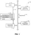
- Referring to
FIG. 1 , a diagram 100 of an aircraft system with anautomated tuning panel 102 is shown. The aircraft system includes anaircraft data bus 104. A flight management computer (FMC) 106 communicates with a control display unit (CDU) 108 by transmitting message(s) 116 along theaircraft data bus 104. The FMC 106 may include a navigation database that provides information about airports, routes, or a combination thereof. The FMC 106 may also be configured to identify an aircraft's current position, determine speeds for an autopilot, or a combination thereof. The CDU 108 may be configured to display pages of data provided by the FMC 106 via the message(s) 116. The CDU 108 may also include an input that enables a pilot to input data or send requests for specific data to the FMC 106 via the message(s) 116. Theautomated tuning panel 102, the FMC 106, and the CDU 108 may each be a line-replaceable unit (LRU). - The
automated tuning panel 102 includes amonitoring interface 110 that is configured to couple theautomated tuning panel 102 to theaircraft data bus 104. Themonitoring interface 110 is configured to monitor the message(s) 116 transmitted along theaircraft data bus 104. Theautomated tuning panel 102 may correspond to a navigation (NAV) radio tuning panel. - When the
automated tuning panel 102 detects a particular page in the message(s) 116 via themonitoring interface 110, theautomated tuning panel 102 is configured to store target data from the particular page at a memory. The automated tuning panel may compare the target data to data already stored in the memory. The automated tuning panel may only store the target data into memory responsive to the target data being distinct from the data already stored in memory. The memory that the automatedtuning panel 102 stores the target data in may be a standby memory like standby memory 212 ofFIGs. 2A and 2B . The target data may include a particular radio frequency. For example, the particular page may be an approach page labeled with the string "approach ref' and the target data may be an instrument landing system (ILS) frequency on the approach page. Alternatively, the target data may be any frequency that can be processed by the automated tuning panel such as a ground-based augmentation landing system (GLS) frequency, a very high frequency omni-directional range (VOR) frequency, a distance measuring equipment (DME) frequency, or a microwave landing system (MLS) frequency. The particular page may be any page that includes a frequency that would be desired by a pilot. - In some examples, the automated
tuning panel 102 may be configured to change the frequency stored in memory to a frequency not specifically identified in a second page. For example, themonitoring interface 110 may detect that a second particular page is being transmitted via the message(s) 116. The second particular page may indicate that the aircraft is performing or subject to a required navigation performance (RNP) approach. During an RNP approach, an aircraft is expected to tune to a VOR frequency to receive proper navigation assistance. Upon detecting that a VOR frequency is to be used, the automatedtuning panel 102 may store a VOR frequency into the standby memory for pilot verification before tuning. The VOR frequency may be a predetermined VOR frequency stored in the memory or it may be a VOR frequency determined via random number generation or any other means of number generation. - The automated
tuning panel 102 may include inputs (e.g., the buttons illustrated inFIG. 1 ) that enable the pilot to enter a frequency into the standby memory. Additionally, the automated tuning panel may include a button that enables a pilot to swap a frequency stored in the standby memory with a frequency stored in an active memory. The active memory stores a frequency that aradio 112 is currently tuned to. Pressing the button to swap the two frequencies may result in a message being sent to an aircraft control system via theaircraft data bus 104. The aircraft control system may include theradio 112. Alternatively, the automated tuning panel may have adirect connection 114 with theradio 112, and the automatedtuning panel 102 may transmit a message to theradio 112 via the direct connection. The standby frequency may not be transferred to the radio prior to the button being pressed. - By having the automated
tuning panel 102 require the pilot to verify the frequency before sending the frequency to the radio, operating procedures can remain the same. Additionally, by auto populating the standby memory, errors in data entry can be reduced while also saving pilots time during important procedures such as an arrival procedure. - Referring to
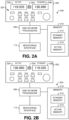
FIG. 2A , a diagram of an automatedtuning panel system 200 is shown. The automatedtuning panel system 200 may include an automatedtuning panel 202. The automatedtuning panel system 200 may further include one ormore processors 206, themonitoring interface 110 ofFIG. 1 , one or more user input device(s) 222 (including, for example,button 204 and/or one or more other buttons, knobs, switches, etc.), and a memory 210. The automatedtuning panel system 200 is one example ofautomated tuning panel 102 as illustrated and described with reference toFIG. 1 . - The automated
tuning panel 202 includes adisplay 220 for an active frequency of theradio 112 ofFIG. 1 and adisplay 208 for a standby frequency. A pilot can adjust the active frequency or the standby frequency using the user interface device(s) 222. The active frequency may be stored in an active memory 214 of the memory 210. The standby frequency may be stored in a standby memory 212 of the memory 210. The standby memory 212 and active memory 214 may be two locations in memory that are identified as either active or standby based on the value of a register. Alternatively, the active memory and standby memories may be two separate memory devices that are part of memory 210 or two different sections of a single memory device that is part of memory 210. The memory 210 may also store instructions configured to be executed by the one ormore processors 206. - In
FIG. 2A , the active frequency is shown to be 118.035 ondisplay 220 and the standby frequency is shown to be 136.990 on thedisplay 208. Accordingly, if themonitoring interface 110 detected a particular page, the one ormore processors 206 would overwrite the 136.990 frequency with the target data. - User input via a user input device, such as the
button 204, instructs the one ormore processors 206 to swap the frequency stored in active memory with the frequency stored in standby memory. Swapping the frequencies may be achieved by overwriting the frequencies in their current locations in memory, writing the frequencies to new locations in memory and changing pointers to point to the new locations, changing pointers in memory, or changing a value of a flag that identifies which memory location is standby and which is active. - Referring to
FIG. 2B , a diagram of the automatedtuning panel system 200 is shown. InFIG. 2B , thebutton 204 has been pressed. Accordingly, the frequency 118.035 has been moved from being the active frequency to the standby frequency and is presented via thedisplay 220, and the frequency 136.990 has been moved from being the standby frequency to the active frequency and is presented via thedisplay 208. If themonitoring interface 110 detected a communication of relevant data over the aircraft data bus 104 (e.g., a page that included navigation radio data), the one ormore processors 206 would overwrite the 118.035 frequency with the target data from the bus. - Referring to
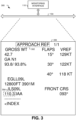
FIG. 3 , a diagram 300 of anapproach reference page 306 being monitored by themonitoring interface 110 is shown. The page includes a specified string 302 and target data 304. Themonitoring interface 110 ofFIGs. 1 ,2A, and 2B may monitor theaircraft data bus 104 ofFIG. 1 for a page containing the specified string 302. InFIG. 3 the specified string 302 is "approach ref." In alternate examples, the specified string could correspond to any string that appears on a page containing a desired frequency. - Upon detecting a message containing the specified string 302, the one or
more processors 206 ofFIGs. 2A and 2B may process the page to identify target data 304. In some examples, the one ormore processors 206 may search for content of a data field with a predetermined offset to the specified string 302. Alternatively, the one ormore processors 206 may search for a specific string that occurs before the target data 304. For example, the one or more processors may search for the string "Front CRS" that occurs before the target data 304. Any other search method may be used to identify the target data 304. - Referring to
FIG. 4 , a particular illustrative example of a method is depicted and generally designated 400. In some examples, operations of themethod 400 are initiated, performed, or controlled by a processor, such as by one ormore processors 206 ofFIGs. 2A and 2B executing instructions. - The
method 400 includes monitoring, atblock 402, at one or more processors of a first line-replaceable unit (LRU), communications over an aircraft data bus between a pilot interface device and a second LRU. For example, the automatedtuning panel 102 ofFIG. 1 or the automatedtuning panel system 200 ofFIGs. 2A and 2B may monitor theaircraft data bus 104 for the message(s) 116 between theFMC 106 and theCDU 108. The automatedtuning panel 102 or the automatedtuning panel system 200 may monitor for messages containing specific data, a specific header, a specific sending device, a specific recipient device, or any other message attributes that assists in identifying a particular message. - The
method 400 includes, in response to detecting a particular page being transmitted over the aircraft data bus, extracting, atblock 404, target data associated with the particular page from the aircraft data bus. For example, the particular page may be an approach ref page like theapproach ref page 306 ofFIG. 3 or any other page of data that contains a relevant frequency. The particular page may be detected based on the page including text labeling it as an "approach ref' page such as the specified string 302, the page containing specific data, a specific target address, a specific sending address, or any other message attribute that assists in identifying the particular page. The target data may be a particular frequency like the target data 304 ofFIG. 3 or any other data contained in the particular page. - The
method 400 includes storing, atblock 406, the target data at a memory associated with the one or more processors. For example, the memory may be the memory 210 or the standby memory 212 ofFIGs. 2A and 2B . - Referring to
FIG. 5 , a flowchart illustrative of a life cycle of an aircraft that includes the automatedtuning panel 102 is shown and designated 500. During pre-production, theexemplary life cycle 500 includes, at 502, specification and design of an aircraft, such as theaircraft 600 described with reference toFIG. 6 . During specification and design of the aircraft, thelife cycle 500 may include specification and design of the automatedtuning panel 102. At 504, thelife cycle 500 includes material procurement, which may include procuring materials for the automatedtuning panel 102. - During production, the
life cycle 500 includes, at 506, component and subassembly manufacturing and, at 508, system integration of the aircraft. For example, thelife cycle 500 may include component and subassembly manufacturing of the automatedtuning panel 102 and system integration of the automatedtuning panel 102. At 510, thelife cycle 500 includes certification and delivery of the aircraft and, at 512, placing the aircraft in service. Certification and delivery may include certification of the automatedtuning panel 102 to place the automatedtuning panel 102 in service. While in service by a customer, the aircraft may be scheduled for routine maintenance and service (which may also include modification, reconfiguration, refurbishment, and so on). At 514, thelife cycle 500 includes performing maintenance and service on the aircraft, which may include performing maintenance and service on the automatedtuning panel 102. - Each of the processes of the
life cycle 500 may be performed or carried out by a system integrator, a third party, and/or an operator (e.g., a customer). For the purposes of this description, a system integrator may include without limitation any number of aircraft manufacturers and major-system subcontractors; a third party may include without limitation any number of venders, subcontractors, and suppliers; and an operator may be an airline, leasing company, military entity, service organization, and so on. - Examples of the disclosure may be described in the context of an
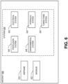
aircraft 600 as shown inFIG. 6 . Theaircraft 600 includes anairframe 618 with a plurality of systems 620 (e.g., high-level systems) and an interior 622. Examples of thesystems 620 include one or more of apropulsion system 624, anelectrical system 626, anenvironmental system 628, ahydraulic system 630, and thetuning panel system 200. Other systems can also be included. - The
tuning panel system 200 is configured to support examples of computer-implemented methods and computer-executable program instructions (or code) according to the present disclosure. For example, thetuning panel system 200 is configured to execute instructions to initiate, perform, or control one or more operations described with reference toFIGS. 1-4 . -
FIG. 7 is an illustration of a block diagram of acomputing environment 700 including acomputing device 710. Thecomputing device 710 is configured to support examples of computer-implemented methods and computer-executable program instructions (or code) according to the present disclosure. In some examples, thecomputing device 710, or portions thereof, executes instructions to initiate, perform, or control operations described herein. To illustrate, thecomputing device 710 may include, correspond to, or be included within the automatedtuning panel 102 of anyFIG. 1 or thetuning panel system 200 ofFIGs. 2A and 2B . - The
computing device 710 includes one ormore processors 720. The one ormore processors 720 are configured to communicate with asystem memory 730, one ormore storage devices 742, one or more input/output interfaces 750, one or more communications interface(s) 760, or a combination thereof. - Depending on the particular implementation, the
system memory 730 includes volatile memory devices (e.g., random access memory (RAM) devices), nonvolatile memory devices (e.g., read-only memory (ROM) devices, programmable read-only memory, or flash memory), one or more other memory devices, or a combination thereof. InFIG. 7 , thesystem memory 730 stores anoperating system 732, which can include a basic input/output system for booting thecomputing device 710 as well as a full operating system to enable thecomputing device 710 to interact with users, other programs, and other devices. The particular example ofFIG. 7 also depicts that thesystem memory 730 stores one or more applications 734 executable by the one ormore processors 720. In some examples, the one or more applications 734 include instructions executable by the one ormore processors 720 to transmit signals between components of thecomputing device 710, such as thesystem memory 730, the one ormore storage devices 742, the one or more input/output interfaces 750, the one or more communications interface(s) 760, or a combination thereof. The particular example ofFIG. 7 also depicts that the system memory 730 (e.g., one or more memory devices)stores program data 736.Program data 736 may include any data necessary for operation of the one or more application 734. - In some examples, the one or
more storage devices 742 include nonvolatile storage devices, such as magnetic disks, optical disks, or flash memory devices. In some examples, the one ormore storage devices 742 include removable memory devices, non-removable memory devices or both. In some cases, the one ormore storage devices 742 are configured to store an operating system, images of operating systems, applications, and program data. In some examples, thesystem memory 730, the one ormore storage devices 742, or both, include tangible computer-readable media. As use herein, a storage device (e.g., the storage device 742) is a hardware device, and is not merely a signal. - In the example of
FIG. 7 , the one ormore processors 720 are configured to communicate with the one or more input/output interfaces 750 to enable thecomputing device 710 to communicate with one or more input/output devices 770 to facilitate user interaction. In some examples, the one or more input/output interfaces 750 include serial interfaces (e.g., universal serial bus (USB) interfaces or Institute of Electrical and Electronics Engineers (IEEE) 1394 interfaces), parallel interfaces, display adapters, audio adapters, one or more other interfaces, or a combination thereof. In some examples, the one or more input/output devices 770 include keyboards, pointing devices, displays, speakers, microphones, touch screens, one or more other devices, or a combination thereof. In some examples, the one ormore processors 720 are configured to detect interaction events based on user input received via the one or more input/output interfaces 750. The one or more input/output devices 770 may include thecontrol display unit 108 or theFMC 106. For example, the one or more input/output interfaces 750 may include interfaces that connect thecomputing device 710 to theaircraft data bus 104. - In some examples, the one or
more processors 720 are configured to communicate with (or send signals to) one ormore devices 780 using the one or more communications interface(s) 760. In some examples, the communications interface(s) 760 include one or more wired interfaces (e.g., Ethernet interfaces), one or more wireless interfaces that comply with an IEEE 802.11 communication protocol, one or more other wireless interfaces, one or more optical interfaces, one or more other network interfaces, or a combination thereof. In some examples, the one ormore devices 780 include host computers, servers, workstations, line replaceable units of an aircraft, one or more other computing devices, or a combination thereof. - Although one or more of
FIGS. 1-7 illustrate systems, apparatuses, and/or methods according to the teachings of the disclosure, the disclosure is not limited to these illustrated systems, apparatuses, and/or methods. One or more functions or components of any ofFIGS. 1-7 as illustrated or described herein may be combined with one or more other portions of another ofFIGS. 1-7 . For example, one or more elements of themethod 400 ofFIG. 4 may be performed in combination with other operations described herein. Accordingly, no single example described herein should be construed as limiting and examples of the disclosure may be suitably combined without departing from the teachings of the disclosure. As an example, one or more operations described with reference toFIGS. 1-7 may be optional, may be performed at least partially concurrently, and/or may be performed in a different order than shown or described. - Examples of the disclosure are described further with reference to the following set of interrelated clauses:
-
Clause 1 includes a line-replaceable unit (LRU) for an aircraft, the LRU comprising: an interface configured to couple to an aircraft data bus; one or more processors coupled to the interface and configured to: monitor communications over the aircraft data bus between a pilot interface device and a second LRU, wherein the LRU is distinct from the second LRU and is distinct from the pilot interface device; in response to detecting a particular page being transmitted over the aircraft data bus, extract target data associated with the particular page from the aircraft data bus; and store the target data at a memory associated with the one or more processors.. -
Clause 2 includes the LRU ofClause 1 further comprising a user interface, wherein the one or more processors are further configured to transmit the target data from the memory to an aircraft control system responsive to receiving user input from the user interface. -
Clause 3 includes the LRU ofClause 2 wherein the aircraft control system includes a radio tuning device configured to tune a radio to a particular radio frequency identified in the target data. -
Clause 4 includes the LRU of any ofClauses 1 to 3 wherein the one or more processors correspond to a navigation (NAV) radio tuning panel. -
Clause 5 includes the LRU of any ofClauses 1 to 4 wherein the pilot interface device comprises a control display unit (CDU). -
Clause 6 includes the LRU of any ofClauses 1 to 5 wherein the second LRU comprises a flight management computer (FMC). -
Clause 7 includes the LRU of any ofClauses 1 to 6 further comprising a display device configured to output data stored in the memory. -
Clause 8 includes a method including monitoring, at one or more processors of a first line-replaceable unit (LRU), communications over an aircraft data bus between a pilot interface device and a second LRU, wherein the first LRU is distinct from the second LRU and is distinct from the pilot interface device; in response to detecting a particular page being transmitted over the aircraft data bus, extracting target data associated with the particular page from the aircraft data bus; and storing the target data at a memory associated with the one or more processors. -
Clause 9 includes the method ofClause 8 further comprising comparing the target data to stored data stored at the memory, wherein the target data is stored at the memory responsive to the target data being distinct from the stored data. - Clause 10 includes the method of
Clause - Clause 11 includes the method of any of
Clauses 8 to 10 further comprising comparing monitored data communicated on the aircraft data bus to detect a specified string, wherein the particular page is detected responsive to the specified string being detected. - Clause 12 includes the method of Clause 11 wherein the specified string includes "approach ref."
- Clause 13 includes the method of Clause 11 or 12 wherein the target data corresponds to content of a data field having a predetermined offset to the specified string.
- Clause 14 includes the method of any of
Clauses 8 to 13 wherein the target data corresponds to an instrument landing system (ILS) frequency. - Clause 15 includes the method of any of
Clauses 8 to 13 wherein the target data corresponds to a ground-based augmentation system (GBAS) landing system frequency. - Clause 16 includes the method of any of
Clauses 8 to 15 wherein the target data is stored in memory as a standby radio frequency, and further comprising transmitting the standby radio frequency from the memory to a radio tuning device responsive to receiving user input from a user interface, wherein the standby radio frequency is not transmitted to the radio tuning device prior to receiving the user input. - Clause 17 includes the method of Clause 16 wherein the memory identifies an active radio frequency, and wherein the active radio frequency is stored as a second standby radio frequency and the standby radio frequency is stored as a second active radio frequency responsive to the user input.
- Clause 18 includes a computer-readable storage device storing instructions that, when executed by one or more processors of a line-replaceable unit (LRU), cause the one or more processors to: monitor communications over a data bus between an interface device and a second LRU, wherein the LRU is distinct from the second LRU and is distinct from the interface device; in response to detecting a particular page being transmitted over the data bus, extracting target data associated with the particular page from the data bus; and storing the target data at a memory.
- Clause 19 includes the computer-readable storage device of Clause 18 wherein the instructions further cause the one or more processors to compare the target data to standby frequency data stored at the memory, and wherein the target data is stored at the memory responsive to the target data being distinct from the stored data.
- Clause 20 includes the computer-readable storage device of Clause 18 or 19 wherein the particular page corresponds to an approach page.
- Clause 21 includes an aircraft comprising a line-replaceable unit (LRU), an aircraft data bus, a pilot interface device and a second LRU, wherein the LRU comprises: an interface configured to couple to the aircraft data bus; one or more computer processors coupled to the interface and configured to: monitor communications over the aircraft data bus between the pilot interface device and the second LRU, wherein the LRU is distinct from the second LRU and is distinct from the pilot interface device; in response to detecting a particular page being transmitted over the aircraft data bus, extract target data associated with the particular page from the aircraft data bus; and store the target data at a memory associated with the one or more computer processors.
- Clause 22 includes the aircraft of Clause 21 wherein the aircraft further comprises an aircraft control system and the LRU further comprises a user interface, wherein the one or more computer processors are further configured to transmit the target data from the memory to the aircraft control system responsive to receiving user input from the user interface.
- Clause 23 includes the aircraft of Clause 22 wherein the aircraft control system includes a radio tuning device configured to tune a radio to a particular radio frequency identified in the target data.
- Clause 24 includes the aircraft of any of Clauses 21 to 23 wherein the one or more computer processors correspond to a navigation (NAV) radio tuning panel.
- Clause 25 includes the aircraft of any of Clauses 21 to 24 wherein the pilot interface device comprises a control display unit (CDU).
- Clause 26 includes the aircraft of any of Clauses 21 to 25 wherein the second LRU comprises a flight management computer (FMC).
- Clause 27 includes the aircraft of any of Clauses 21 to 26 wherein the LRU further comprises a display device configured to output data stored in the memory.
- Examples described above are illustrative and do not limit the disclosure. It is to be understood that numerous modifications and variations are possible in accordance with the principles of the present disclosure.
- The illustrations of the examples described herein are intended to provide a general understanding of the structure of the various examples. The illustrations are not intended to serve as a complete description of all of the elements and features of apparatus and systems that utilize the structures or methods described herein. Many other examples may be apparent to those of skill in the art upon reviewing the disclosure. Other examples may be utilized and derived from the disclosure, such that structural and logical substitutions and changes may be made without departing from the scope of the claims. For example, method operations may be performed in a different order than shown in the figures or one or more method operations may be omitted. Accordingly, the disclosure and the figures are to be regarded as illustrative rather than restrictive.
- Moreover, although specific examples have been illustrated and described herein, it should be appreciated that any subsequent arrangement designed to achieve the same or similar results may be substituted for the specific examples shown. This disclosure is intended to cover any and all subsequent adaptations or variations of various examples. Combinations of the above examples, and other examples not specifically described herein, will be apparent to those of skill in the art upon reviewing the description.
- The Abstract of the Disclosure is submitted with the understanding that it will not be used to interpret or limit the scope or meaning of the claims. In addition, in the foregoing Detailed Description, various features may be grouped together or described in a single example for the purpose of streamlining the disclosure. Examples described above illustrate but do not limit the disclosure. It should also be understood that numerous modifications and variations are possible in accordance with the principles of the present disclosure. As the following claims reflect, the claimed subject matter may be directed to less than all of the features of any of the disclosed examples. Accordingly, the scope of the disclosure is defined by the following claims.
Claims (15)
- A line-replaceable unit (LRU) (102) for an aircraft (600), the line-replaceable unit (102) comprising:an interface (110) configured to couple to an aircraft data bus (104); andone or more computer processors (206) coupled to the interface and configured to:monitor communications over the aircraft data bus (104) between a pilot interface device (108) and a second line-replaceable unit (106), wherein the line-replaceable unit (102) is distinct from the second line-replaceable unit (106) and is distinct from the pilot interface device (108);in response to detecting a particular page (306) being transmitted over the aircraft data bus (104), extract target data (304) associated with the particular page from the aircraft data bus (104); andstore the target data (304) at a memory (210) associated with the one or more computer processors (206).
- The line-replaceable unit (102) of claim 1, further comprising a user interface (204), wherein the one or more computer processors (206) are further configured to transmit the target data (304) from the memory (210) to an aircraft control system responsive to receiving user input from the user interface (204).
- The line-replaceable unit (102) of claim 2, wherein the aircraft control system includes a radio tuning device (112) configured to tune a radio to a particular radio frequency identified in the target data (304).
- The line-replaceable unit (102) of any preceding claim, wherein the one or more computer processors (206) are integrated within a navigation (NAV) radio tuning panel (102, 202).
- The line-replaceable unit (102) of any preceding claim, wherein the pilot interface device (108) comprises a control display unit (CDU) (108) and/or the second line-replaceable unit (106) comprises a flight management computer (FMC) (106).
- The line-replaceable unit (102) of any preceding claim, further comprising a display device (208) configured to output data stored in the memory (210).
- An aircraft comprising the line-replaceable unit (102) of any preceding claim, a pilot interface device (108), a second line-replaceable unit (106) and an aircraft data bus (104) linking the pilot interface device (108) and the second line-replaceable unit (106).
- A method comprising:monitoring, at one or more computer processors (206) of a first line-replaceable unit (LRU) (102, 202), communications over an aircraft data bus (104) between a pilot interface device (108) and a second line-replaceable unit (106), wherein the first line-replaceable unit (102, 202) is distinct from the second line-replaceable unit (106) and is distinct from the pilot interface device (108);in response to detecting a particular page (306) being transmitted over the aircraft data bus (104), extracting target data (304) associated with the particular page from the aircraft data bus (104); andstoring the target data (304) at a memory (210) associated with the one or more computer processors (206).
- The method of claim 8, further comprising comparing the target data (304) to stored data stored at the memory (210), wherein the target data (304) is stored at the memory (210) responsive to the target data (304) being distinct from the stored data.
- The method of claim 8 or 9, wherein the particular page corresponds to an approach reference page (306).
- The method of any of claims 8 to 10, further comprising comparing monitored data communicated on the aircraft data bus (104) to a specified string, wherein the particular page is detected responsive to the specified string being detected and, optionally, the specified string includes "approach ref' (302).
- The method of claim 11, wherein the target data (304) corresponds to content of a data field having a predetermined offset to the specified string.
- The method of any of claims 8 to 12, wherein the target data (304) corresponds to an instrument landing system (ILS) frequency and/or a ground-based augmentation system landing system (GLS) frequency.
- The method of any of claims 8 to 13, wherein:the target data (304) is stored in memory (210) as a standby radio frequency, and further comprising transmitting the standby radio frequency from the memory (210) to a radio tuning device (112) responsive to receiving user input from a user interface (204), wherein the standby radio frequency is not transmitted to the radio tuning device (210) prior to receiving the user input; and, optionally,the memory (210) identifies an active radio frequency, and wherein the active radio frequency is stored as a second standby radio frequency and the standby radio frequency is stored as a second active radio frequency responsive to the user input.
- A computer program comprising computer program instructions (734) that, when executed by one or more computer processors (206), cause the one or more computer processors (206) to perform the method of any of claims 8 to 14, or a computer-readable storage device (730) having stored thereon such a computer program.
Applications Claiming Priority (1)
| Application Number | Priority Date | Filing Date | Title |
|---|---|---|---|
| US18/318,471 US12306779B2 (en) | 2023-05-16 | 2023-05-16 | Systems and methods for a smart navigation tuning panel |
Publications (1)
| Publication Number | Publication Date |
|---|---|
| EP4464603A1 true EP4464603A1 (en) | 2024-11-20 |
Family
ID=90417350
Family Applications (1)
| Application Number | Title | Priority Date | Filing Date |
|---|---|---|---|
| EP24165102.5A Pending EP4464603A1 (en) | 2023-05-16 | 2024-03-21 | Systems and methods for a smart navigation tuning panel |
Country Status (3)
| Country | Link |
|---|---|
| US (1) | US12306779B2 (en) |
| EP (1) | EP4464603A1 (en) |
| CN (1) | CN119002326A (en) |
Citations (3)
| Publication number | Priority date | Publication date | Assignee | Title |
|---|---|---|---|---|
| US20020009994A1 (en) * | 2000-07-10 | 2002-01-24 | Sample William G. | Aircraft frequency identification |
| US11163067B2 (en) * | 2020-04-02 | 2021-11-02 | The Boeing Company | Interface device and method for retrofitting an airplane with GNSS landing capability |
| US11342957B2 (en) * | 2019-03-01 | 2022-05-24 | Honeywell International Inc. | Three-way radio switch to allow for manual and automatic standby frequencies |
Family Cites Families (17)
| Publication number | Priority date | Publication date | Assignee | Title |
|---|---|---|---|---|
| US5184312A (en) | 1985-10-13 | 1993-02-02 | The Boeing Company | Distributed built-in test equipment system for digital avionics |
| US5809402A (en) | 1992-10-07 | 1998-09-15 | The Boeing Company | ACARS/VHF transceiver interface unit (AVIU) |
| FR2907997B1 (en) | 2006-10-26 | 2008-12-19 | Airbus France Sa | AIRCRAFT COMMUNICATION SYSTEM WITH RECONFIGURABLE DISPLAY |
| US8081933B2 (en) | 2007-07-13 | 2011-12-20 | Honeywell International Inc. | Reconfigurable aircraft radio communications system |
| US8019338B2 (en) | 2008-05-29 | 2011-09-13 | Honeywell International Inc. | Reconfigurable aircraft communications system with integrated avionics communication router and audio management functions |
| US9159241B1 (en) | 2011-04-15 | 2015-10-13 | The Boeing Company | Methods, systems, and apparatus for synthetic instrument landing system (SILS) |
| CN103048984B (en) | 2013-01-17 | 2013-12-18 | 中国民航大学 | Multi-channel ARINC(aeronautical radio incorporated) 700 bus monitoring device and realizing method thereof |
| CN203433354U (en) | 2013-09-12 | 2014-02-12 | 成都成电光信科技有限责任公司 | Distributed monitoring system for aircraft |
| CN204667662U (en) | 2015-06-03 | 2015-09-23 | 江苏工程职业技术学院 | A kind of aircraft VHF communication system analogue means |
| EP3307619A1 (en) * | 2015-06-11 | 2018-04-18 | Engineered Arresting Systems Corporation | Aircraft wheel braking performance communications systems and methods |
| US10203700B2 (en) * | 2016-02-29 | 2019-02-12 | Garmin International, Inc. | Emergency autoland system |
| CN107689895A (en) | 2017-07-04 | 2018-02-13 | 西安飞机工业(集团)有限责任公司 | A kind of detection method and detection means of aviation ARINC429 signals |
| US10850397B2 (en) * | 2018-04-19 | 2020-12-01 | Aurora Flight Sciences Corporation | System and method for providing in-cockpit actuation of aircraft controls |
| US10992372B2 (en) | 2018-05-17 | 2021-04-27 | Honeywell International Inc. | Methods and systems for assisting radio frequency selection |
| US10861341B2 (en) * | 2018-12-11 | 2020-12-08 | Honeywell International Inc. | Method and system for prompting aircraft task reminders |
| US20200380875A1 (en) * | 2019-05-30 | 2020-12-03 | Honeywell International Inc. | Method and system for flight safety analytics display |
| CN110471880B (en) | 2019-07-19 | 2021-01-12 | 哈尔滨工业大学 | An ARINC429 bus module based on FPGA supporting Label number screening and its data transmission method |
-
2023
- 2023-05-16 US US18/318,471 patent/US12306779B2/en active Active
-
2024
- 2024-03-21 EP EP24165102.5A patent/EP4464603A1/en active Pending
- 2024-03-29 CN CN202410377999.5A patent/CN119002326A/en active Pending
Patent Citations (3)
| Publication number | Priority date | Publication date | Assignee | Title |
|---|---|---|---|---|
| US20020009994A1 (en) * | 2000-07-10 | 2002-01-24 | Sample William G. | Aircraft frequency identification |
| US11342957B2 (en) * | 2019-03-01 | 2022-05-24 | Honeywell International Inc. | Three-way radio switch to allow for manual and automatic standby frequencies |
| US11163067B2 (en) * | 2020-04-02 | 2021-11-02 | The Boeing Company | Interface device and method for retrofitting an airplane with GNSS landing capability |
Also Published As
| Publication number | Publication date |
|---|---|
| US20240385980A1 (en) | 2024-11-21 |
| CN119002326A (en) | 2024-11-22 |
| US12306779B2 (en) | 2025-05-20 |
Similar Documents
| Publication | Publication Date | Title |
|---|---|---|
| US9830910B1 (en) | Natrual voice speech recognition for flight deck applications | |
| USRE49067E1 (en) | Flight deck multifunction control display unit | |
| CN113486031A (en) | Method for updating departure flight data and related equipment | |
| US9171273B2 (en) | Integrated electronic checklist display system | |
| US10797945B2 (en) | Methods are provided for flight management services in a cloud environment | |
| US9047013B2 (en) | Avionic data dictionary based messaging system and method | |
| US20160200455A1 (en) | Line replacement unit (lru) replacement process | |
| US9432611B1 (en) | Voice radio tuning | |
| US9223413B2 (en) | Next action page key for system generated messages | |
| US11334829B2 (en) | Methods and systems for electronic checklist data references | |
| AU2015200543A1 (en) | Vehicle configuration driven loading of software parts | |
| US9557189B2 (en) | Communication of flight management computer data via a wireless interface of a control display unit | |
| CN104865913A (en) | System and method to view, verify, and send datalink downlink messaging | |
| EP3534304A1 (en) | Systems and methods for associating and presenting aviation checklist data and electronic circuit breaker (ecb) data onboard an aircraft | |
| US10032382B2 (en) | Communication of flight management computer data via a wireless interface of a data capture device | |
| EP3483860A1 (en) | Methods are provided for flight management services in a cloud environment | |
| US11521501B2 (en) | Method, apparatus and system for operating waypoint, ground station and computer readable storage medium | |
| EP3421939A1 (en) | Systems, devices, and methods for using a multi-function control and display unit (mcdu) communication architecture onboard an aircraft | |
| US12306779B2 (en) | Systems and methods for a smart navigation tuning panel | |
| US20220084514A1 (en) | System and method for smart validation of pre-conditions in executing pilot voice commands | |
| US20030169301A1 (en) | Display selection identification enhancement by de-emphasizing non-essential information | |
| CN107832225A (en) | A kind of flight management software test case design method | |
| US20210001997A1 (en) | Self-contained small avionics systems | |
| US20240383612A1 (en) | Systems and methods for aircraft thrust rating model processing | |
| US10706727B1 (en) | Adaptive flight display radio tuning system |
Legal Events
| Date | Code | Title | Description |
|---|---|---|---|
| PUAI | Public reference made under article 153(3) epc to a published international application that has entered the european phase |
Free format text: ORIGINAL CODE: 0009012 |
|
| STAA | Information on the status of an ep patent application or granted ep patent |
Free format text: STATUS: THE APPLICATION HAS BEEN PUBLISHED |
|
| AK | Designated contracting states |
Kind code of ref document: A1 Designated state(s): AL AT BE BG CH CY CZ DE DK EE ES FI FR GB GR HR HU IE IS IT LI LT LU LV MC ME MK MT NL NO PL PT RO RS SE SI SK SM TR |
|
| STAA | Information on the status of an ep patent application or granted ep patent |
Free format text: STATUS: REQUEST FOR EXAMINATION WAS MADE |
|
| 17P | Request for examination filed |
Effective date: 20250328 |
|
| GRAP | Despatch of communication of intention to grant a patent |
Free format text: ORIGINAL CODE: EPIDOSNIGR1 |
|
| STAA | Information on the status of an ep patent application or granted ep patent |
Free format text: STATUS: GRANT OF PATENT IS INTENDED |
|
| RIC1 | Information provided on ipc code assigned before grant |
Ipc: B64D 43/00 20060101AFI20260115BHEP Ipc: G01C 23/00 20060101ALI20260115BHEP Ipc: G08G 5/21 20250101ALI20260115BHEP Ipc: G08G 5/26 20250101ALI20260115BHEP Ipc: G08G 5/54 20250101ALI20260115BHEP |
|
| INTG | Intention to grant announced |
Effective date: 20260130 |
|
| P01 | Opt-out of the competence of the unified patent court (upc) registered |
Free format text: CASE NUMBER: UPC_APP_0003809_4464603/2026 Effective date: 20260202 |