EP4464542A1 - Wall mountable backplate for securing an electric vehicle service equipment (evse), method of installing an evse, wall box for charging an electric vehicle and an electric vehicle charging system - Google Patents
Wall mountable backplate for securing an electric vehicle service equipment (evse), method of installing an evse, wall box for charging an electric vehicle and an electric vehicle charging system Download PDFInfo
- Publication number
- EP4464542A1 EP4464542A1 EP23173678.6A EP23173678A EP4464542A1 EP 4464542 A1 EP4464542 A1 EP 4464542A1 EP 23173678 A EP23173678 A EP 23173678A EP 4464542 A1 EP4464542 A1 EP 4464542A1
- Authority
- EP
- European Patent Office
- Prior art keywords
- evse
- housing
- backplate
- wall
- electric vehicle
- Prior art date
- Legal status (The legal status is an assumption and is not a legal conclusion. Google has not performed a legal analysis and makes no representation as to the accuracy of the status listed.)
- Pending
Links
Images


Classifications
-
- H—ELECTRICITY
- H02—GENERATION; CONVERSION OR DISTRIBUTION OF ELECTRIC POWER
- H02G—INSTALLATION OF ELECTRIC CABLES OR LINES, OR OF COMBINED OPTICAL AND ELECTRIC CABLES OR LINES
- H02G3/00—Installations of electric cables or lines or protective tubing therefor in or on buildings, equivalent structures or vehicles
- H02G3/02—Details
- H02G3/08—Distribution boxes; Connection or junction boxes
- H02G3/10—Distribution boxes; Connection or junction boxes for surface mounting on a wall
-
- B—PERFORMING OPERATIONS; TRANSPORTING
- B60—VEHICLES IN GENERAL
- B60L—PROPULSION OF ELECTRICALLY-PROPELLED VEHICLES; SUPPLYING ELECTRIC POWER FOR AUXILIARY EQUIPMENT OF ELECTRICALLY-PROPELLED VEHICLES; ELECTRODYNAMIC BRAKE SYSTEMS FOR VEHICLES IN GENERAL; MAGNETIC SUSPENSION OR LEVITATION FOR VEHICLES; MONITORING OPERATING VARIABLES OF ELECTRICALLY-PROPELLED VEHICLES; ELECTRIC SAFETY DEVICES FOR ELECTRICALLY-PROPELLED VEHICLES
- B60L53/00—Methods of charging batteries, specially adapted for electric vehicles; Charging stations or on-board charging equipment therefor; Exchange of energy storage elements in electric vehicles
- B60L53/30—Constructional details of charging stations
-
- G—PHYSICS
- G06—COMPUTING OR CALCULATING; COUNTING
- G06K—GRAPHICAL DATA READING; PRESENTATION OF DATA; RECORD CARRIERS; HANDLING RECORD CARRIERS
- G06K7/00—Methods or arrangements for sensing record carriers, e.g. for reading patterns
- G06K7/10—Methods or arrangements for sensing record carriers, e.g. for reading patterns by electromagnetic radiation, e.g. optical sensing; by corpuscular radiation
- G06K7/14—Methods or arrangements for sensing record carriers, e.g. for reading patterns by electromagnetic radiation, e.g. optical sensing; by corpuscular radiation using light without selection of wavelength, e.g. sensing reflected white light
- G06K7/1404—Methods for optical code recognition
- G06K7/1408—Methods for optical code recognition the method being specifically adapted for the type of code
- G06K7/1417—2D bar codes
Definitions
- Embodiments of the present disclosure relate to electric vehicle charging equipment (EVSE), particularly wall mountable backplates for securing an EVSE. Further embodiments of the present disclosure relate to a method of installing an EVSE, a wall box for charging an electric vehicle and an electric vehicle charging system.
- EVSE electric vehicle charging equipment
- Electric and hybrid-electric vehicles are an alternative mode of transport to petrol and diesel engine vehicles. These vehicles use an electric motor as a main or an auxiliary driving mechanism, and incorporate a rechargeable battery to power the electric motor. Recent advancements in electric vehicle technology have led to electric vehicles with increased range and speed, which has contributed to an increase in the popularity of electric vehicle ownership. As an increased number of vehicle manufacturers begin to produce electric vehicles, electric vehicle ownership appears set to become commonplace.
- Electric vehicles are generally recharged by connecting the electric vehicle to a specialized charging apparatus (which may be referred to as a charging station or a charging point), which includes a charging connector which couples with a charging port on the vehicle and delivers power to recharge the vehicle's battery.
- the charging stations generally draw electricity from the main power grid, and are therefore provided in locations electrically connected to the main power grid.
- electric vehicle charging stations may be provided at service stations, shopping or leisure venues, or may be provided at the user's home. Electric vehicle recharging is currently much slower than refilling a petrol or diesel vehicle with fuel, and may require a user to recharge their electric vehicle for a long time, for example overnight.
- CPOs charge point operators
- a wall mountable backplate for securing an electric vehicle service equipment (EVSE) to a wall a method of installing an EVSE, and a wall box for charging an electric vehicle according to the independent claims are provided. Further aspects, advantages, and features are apparent from the dependent claims, the description, and the accompanying drawings.
- EVSE electric vehicle service equipment
- a wall mountable backplate for securing an electric vehicle service equipment, EVSE, to a wall.
- the wall mountable backplate includes a housing having one or more openings for guiding one or more cables into the housing.
- the housing is configured for receiving an electrical connector having a plurality of electrical contacts for connecting a plurality of corresponding electrical contacts of the EVSE.
- the housing has one or more positioning elements for mating with corresponding positioning elements of the EVSE.
- the housing has one or more mounting elements for either mounting a front cover for providing an enclosed environmentally protected interior volume or mounting the EVSE to the housing.
- a wall mountable backplate for securing an EVSE is provided which is improved compared to the state of the art.
- the wall mountable backplate according to embodiments of the present disclosure is beneficially provides for the possibility to provide an electrical access point that is configured to facilitate the safe and efficient installation of EVSE in the future.
- the wall mountable backplate as described herein has the advantage that an easy two-step installation can be employed.
- the backplate as described herein is beneficially configured to function as pre-implemented electrical access point which can be connected to a power distribution cabinet by a cable and fixed to the wall by an experienced electrical engineer first. Later, the EVSE can be safely installed by the user himself.
- a method of installing an EVSE includes mounting a wall mountable backplate according any of the embodiments described herein to a wall. Further, the method includes securing the EVSE to the wall mountable backplate.
- a wall box for charging an electric vehicle includes an EVSE secured to a wall mountable backplate according to any of embodiments described herein.
- the EVSE is electrically connected to an electrical connector arranged in the housing of the wall mountable backplate via a plurality of plug-in contacts.
- an electric vehicle charging system is provided.
- the electric vehicle charging system is connected to a power cabinet configured to provide power to the EVSE for operating the EVSE and charging the electric vehicle.
- the wall mountable backplate 10 for securing an electric vehicle service equipment, EVSE 20, to a wall according to the embodiments of the present disclosure is described.
- the wall mountable backplate includes a housing 11 having one or more openings 12 for guiding one or more cables 100 into the housing.
- the housing 11 is configured for receiving an electrical connector 13 having a plurality of electrical contacts 131 for connecting a plurality of corresponding electrical contacts 21 of the EVSE 20.
- the housing 11 has one or more positioning elements 14 for mating with corresponding positioning elements 22 of the EVSE 20.
- the housing 11 has one or more mounting elements 15 for either mounting a front cover 30 for providing an enclosed environmentally protected interior volume or mounting the EVSE 20 to the housing 11.
- an electric vehicle supply equipment may also referred to as electric vehicle charging station, EV charging station, electric recharging point, charging point or charge point.
- the EVSE can be understood as an element in an infrastructure that supplies electric energy for the recharging of electric vehicles.
- a wall mountable backplate can be understood as a mounting platform for an EVSE that need to be securely attached to a wall or any other vertical surface.
- the wall mountable backplate can be understood as a sturdy base onto which the EVSE can be secured.
- the wall mountable backplate is made of durable materials, such as metal and/or plastic.
- a housing of the wall mountable backplate can be understood as an outer casing or enclosure having a back wall 11B and a plurality of side walls 11S, as exemplarily shown in Fig. 1 .
- the back wall 11B of the housing is configured to be mountable to a wall or any other vertical surface.
- the back wall 11B includes a plurality of mounting holes 113 for receiving a mounting elements, such as screws, for mounting the back plate 10 to a wall.
- the mounting holes 113 may be provided in the corner regions of the back wall 11B.
- the mounting holes 113 can be configured for fixing the backplate 10 to a wall by four screws, e.g. M6 screws.
- the side walls 11S of the housing 11 extend away from a front side 111 of the backwall 11B.
- the extension of the side walls 11S away from the backwall 11B is typically larger than the extension the of the electrical connector 13 way from the backwall 11B, as exemplarily shown in Fig. 1 , such that the electrical connector 13 can be arranged within the housing 11.
- an electrical connector having a plurality of electrical contacts can be understood as a device that is configured to provide a secure and reliable electrical connection between two or more wires or conductors.
- the electrical connector contains a certain number of individual conductive elements, referred to as electrical contacts, which are configured to mate with other corresponding contacts, particularly of the EVSE as described herein.
- the expression "one or more positioning elements of the housing for mating with corresponding positioning elements of the EVSE” can be understood in that the housing includes one ore more devices or components which are configured to ensure that the EVSE and the housing are correctly aligned or positioned relative to each other when they are connected or mated together.
- the positioning elements 14 of the housing 11 can be protruding features, particularly horizontally protruding features, e.g. positioning posts or pins, as exemplarily shown in Fig. 1 .
- the corresponding positioning elements 22 of the EVSE 20 can be recesses, notches or holes, particularly vertically extending elongated recesses, notches or holes, as exemplarily shown in Fig. 2 .
- the vertical direction V, the horizontal direction H and the lateral direction L are indicated in Figs. 1, 2 , 3 and 6 . It is to be understood that the positioning elements 14 of the housing 11 and the corresponding positioning elements 22 of the EVSE 20 are arranged and configured such that they fit into each other.
- the expression "one or more mounting elements for either mounting a front cover for providing an enclosed environmentally protected interior volume or mounting the EVSE to the housing" can be understood in that the one or more mounting elements are configured to allow the front cover to be securely mounted as well as to allow the EVSE to be securely mounted. Accordingly, the one or more mounting elements provide for flexible installation options, i.e. mounting a front cover or an EVSE. Accordingly, it is to be understood that typically the EVSE and the front cover include one or more corresponding mounting elements for mating with the one or more mounting elements of the housing.
- enclosed environmentally protected interior volume can be understood as a space that is enclosed and protected from environmental factors such as dust and/or moisture and/or temperature fluctuations.
- the enclosed environmentally protected interior volume refers to the space inside the housing 11 of the wall mountable backplate 10 where the electrical connector 13 is located.
- the front cover 30 can be mounted onto the housing using the mounting elements 15, creating a fully enclosed and sealed environment that protects the electrical connector from exposure to environmental factors.
- the housing 11 includes a compartment 16 for the electrical connector 13.
- a compartment for the electrical connector can be understood as a separate section within the housing of the backplate which is configured for receiving the electrical connector.
- the compartment 16 is provided by a space between a compartment wall 161 and a side wall 11S of the housing 11.
- the compartment wall 161 extends from a front side 111 of a backwall 11B of the housing 11 into the interior volume of the housing 11.
- the compartment is open at the side at which wires 101 are to be connected to the electrical connector 13.
- the front side 111 of the backwall 11B may include a recess 162 for the electrical connector 13.
- the recess 162 is typically provided at the front side 111 of the backwall 11B within the compartment 16.
- the electrical connector 13 can be attached to the front side 111 of the backwall 11B, particularly within the recess 162.
- a position of the electrical connector 13 within the housing 11, particularly within the compartment 16, more particularly within the recess 162 can be fixed by appropriate fixation elements.
- the one or more openings 12 for guiding the one or more cables 100 into the housing are provided in one or more sidewalls 11S of the housing 11.
- a cables 100 includes a plurality of wires 101.
- Fig. 1 shows an example of a cable with 100 with five wires 101.
- the number of wire and the number of the plurality of electrical contacts 131 may vary depending on type of charger, e.g. a three-phase charger and a single-phase charger.
- Three-phase chargers require five terminal blocks for electrical connections: three phase lines, one neutral line, and a ground wire (often called "PE” for "protective earth”).
- Single-phase chargers only require three terminal blocks: one phase line, one neutral line, and a ground wire.
- the one or more positioning elements 14 of the housing are positioning posts or pins, as exemplarily shown in Fig. 1 .
- Fig. 1 shows two positioning elements 14 extending towards the front.
- typically the one or more positioning elements 14 are provided in an upper portion of the housing 11.
- the one or more positioning elements 14 may extend from an upper side wall 11S of the housing 11 towards the front. It is to be understood that typically the one or more positioning elements 14 extend substantially perpendicular to the backwall 11B of housing 11. Accordingly, when the wall mountable backplate 10 is mounted to a wall, typically the one or more positioning elements 14 of the housing extend substantially horizontally.
- the corresponding positioning elements 22 of the EVSE 20 are positioning recesses, notches, or holes.
- the positioning recesses, notches or holes may have an elongated shape, particularly extending in the vertical direction.
- the one or more positioning elements 14 of the housing can be positioning recesses, notches, or holes, and the corresponding positioning elements 22 of the EVSE 20 can be positioning posts or pins.
- the one or more mounting elements 15 of the housing 11 include one or more elements of the group consisting of: one or more snap-in elements configured for mating with one or more corresponding snap-in elements of the front cover 30, one or more snap-in elements configured for mating with one or more corresponding snap-in elements of the of the EVSE 20, and one or more internal threads 151 for mating with one or more screws, particularly one or more anti-theft screws.
- the mounting elements 15 provided on the housing 11 shown in Fig. 1 are female mounting elements and the corresponding mounting elements 23 provided on the EVSE are male mounting elements.
- male and female are used to describe that mounting elements as described herein are complementary components, where the male component typically has a protrusion or extension that fits into a corresponding recess or socket in the female component, for creating a secure and stable connection.
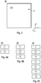
- Fig. 3 shows a schematic front view of a front cover 30 which can be mounted on the front side of the housing 11 for providing an enclosed environmentally protected interior volume as described herein.
- the front side 30F of the front cover includes a hole 31 for receiving a securing element, such as an anti-theft screw. It is to be understood that typically the hole 31 in the front cover 30 is positioned in alignment with the internal thread 151 of the housing 11.
- the front cover 30 can be fixed to the backplate 10, for instance by a M5 anti-theft screw, to prevent the backplate from dust and water and avoid the risk of electric shock.
- the front cover 30 can be removed and instead the EVSE can be installed, i.e. connected to the backplate 10 mounted to the wall.
- the EVSE can be installed, i.e. connected to the backplate 10 mounted to the wall.
- embodiments of the present disclosure beneficially provide for an easier EVSE installation.
- the positioning holes on the EVSE are aligned with the positioning posts on the backplate.
- the EVSE is pushed horizontally towards the backplate.
- the EVSE is pressed down vertically, typically by approximately 4 mm and the EVSE is fixed to the backplate.
- the electrical contacts 21 of the EVSE which may also be referred to as conductive posts, are fixed to the electrical contacts 131 of the electrical connector 13 on the backplate 10.
- the electrical contacts 131 of the electrical connector 13 may also be referred to as card slots.
- the electrical contacts 21 of the EVSE 20 are connected with the electrical contacts 131 of the connector 13, the EVSE is powered on automatically.
- the wall mountable backplate includes a QR code 17 for registering installation information of the wall mountable backplate.
- the QR code can be provided on an outer side of a sidewall 11S of the housing 11, as exemplary shown in Fig. 1 .
- the QR code can be provided at any suitable location on the housing 11.
- the method includes mounting (represented by block 41 in Figs. 4A to 4C ) a wall mountable backplate 10 according any of the embodiments described herein to a wall. Additionally, the method 40 includes securing (represented by block 42 in Figs. 4A to 4C ) the EVSE 20 to the wall mountable backplate 10.
- the method 40 may include removing (represented by block 421 in Figs. 4B and 4C ) a front cover 30 prior to securing the EVSE 20 to the wall mountable backplate 10.
- the method 40 includes scanning (represented by block 43 in Fig. 4C and 5 ) an QR code 17 provided on the wall mountable backplate 10.
- the QR contains identification information of the backplate 10.
- the method 40 may include registering (represented by block 44 in Fig. 4C and 5 ) installation information of the wall mountable backplate provided by the QR code to a back-end server 80.
- scanning and registering is conducted by using a mobile app 90, particularly a smart phone app.
- the method includes downloading (represented by block 45 in Fig. 4C and 5 ) the installation information from the back-end server and configuring (represented by block 46 in Fig. 4C and 5 ) the EVSE according to the installation information.
- Configuring the EVSE may be carried out automatically and may be conducted by using the mobile app 90.
- the QR code on the backplate and a bar code on the EVSE is scanned, e.g. via the mobile app.
- configuring the EVSE may include using a cloning mode.
- the EVSE can have a cloning functionality.
- the installer will be able to activate or deactivate cloning functionality, e.g. by long pressing a hardware button provided on the EVSE, particularly on a side of the EVSE.
- the configured EVSE can then communicate its configuration settings to other EVSEs that send a request for receiving the configuration settings.
- the EVSE When an EVSE is put in cloning mode, first the EVSE will check if it has a valid configuration. If this is the case, the EVSE will send a multicast message over a local network, requesting if there is already another EVSE present that is acting as a configuration source. If the EVSE which sent the multicast message does not receive a message from another configuration source, the EVSE will take up the role as configuration source. If another configuration source does reply, the EVSE which sent the multicast message will indicate an error to the installer, e.g. by a flashing LED and/or beeping. In the case of an error, the EVSE will not enter the cloning mode.
- a configuration source will remain in this mode for a preset amount of time, or until the installer manually ends it.
- this timer i.e. the preset amount of time of the cloning mode
- a leaving of the cloning mode is announced by an audible and/or visible signal, e.g. with a single short beep.
- Unconfigured EVSEs that are put in cloning mode will send out a request over the local network looking for configuration sources. If another EVSE has already been put in configuration source mode, it will respond to this request by sending its configuration settings to the unconfigured EVSE. The unconfigured EVSE will install these configuration settings and confirm the successful configuration, e.g. with an audible and/or visible signal, for instance a single short beep, and leave cloning mode. If there is no configuration source present on the network, the unconfigured EVSE will start listening for an EVSE announcing itself as configuration source. Once this happens the unconfigured EVSE will send out a new request to this configuration source. If no configuration source presents itself within a preset amount of time, the EVSE will leave cloning mode and signal failure to the installer, e.g. with a long beep.
- the process to register and recall installation information can be as follows.
- the installer may scan the QR code 17 on the backplate 10 and open a website and register the installation information via the mobile app 90.
- the installation information can be stored on the back-end server 80.
- the installer may scan the QR code 17 on the backplate 10 to download the installation information via the mobile app 90. Then the app 90 can configure the EVSE 20 in accordance with the downloaded installation information.
- the wall box 50 includes an EVSE 20 secured to a wall mountable backplate 10 according to any embodiments described herein.
- the wall mountable backplate 10 is mounted to a wall 51.
- the EVSE 20 is electrically connected to an electrical connector 13 via a plurality of plug-in connections.
- the plurality of plug-in connections are provided by a connection of the plurality of electrical contacts 131 of the electrical connector 13, as exemplarily shown in Fig. 1 , with the plurality of corresponding electrical contacts 21 of the EVSE 20, as exemplarily shown in Fig. 2 . It is to be understood that the plug-in connections are arranged within the housing 11 of the wall mountable backplate 10.
- the plurality of electrical contacts 131 of the electrical connector 13 can be female contacts and the plurality of corresponding electrical contacts 21 of the EVSE can be male contacts, as exemplarily shown in Figs 1 and 2 .
- the plurality of electrical contacts 131 of the electrical connector 13 may be male contacts and the plurality of corresponding electrical contacts 21 of the EVSE may be female contacts.
- the female contacts are elongated such that when the male contacts are inserted the male contacts can be moved along the elongated direction of the female contacts up to a stop to establish the connection of the female contacts and the male contacts.
- the electric vehicle charging system 60 includes a wallbox 50 according to any embodiments described herein.
- the wall box is connected to a power cabinet 61 configured to provide power to the EVSE for operating the EVSE and charging an electric vehicle 70.
- a charging gun 72 is connected to the wallbox 50 via charging cable 71.
- embodiments described herein beneficially provide for a two-step installation scheme solution, which is characterized in that fixing the EVSE to the backplate is so easy that even an end user can do the job himself.
- the backplate is configured for providing a pre-implemented electrical access point.
- the backplate is connected to the power distribution cabinet and fixed to the wall by an experienced electrical engineer at early stage. The experienced electrical engineer may scan the QR code on the backplate and register the installation information for the backplate to the back-end server via a mobile app.
- a front cover can be installed after the early-stage installation.
- the front cover is removed first, then the EVSE can be fixed to the backplate and powered on.
- installer e.g. the end user, can scan the QR code on the backplate and the bar code on the EVSE via a mobile app and the installation information will be downloaded from the back-end server and configured to the EVSE automatically.
Landscapes
- Engineering & Computer Science (AREA)
- Physics & Mathematics (AREA)
- Mechanical Engineering (AREA)
- Transportation (AREA)
- Power Engineering (AREA)
- Toxicology (AREA)
- Artificial Intelligence (AREA)
- Computer Vision & Pattern Recognition (AREA)
- General Physics & Mathematics (AREA)
- Theoretical Computer Science (AREA)
- General Health & Medical Sciences (AREA)
- Electromagnetism (AREA)
- Health & Medical Sciences (AREA)
- Architecture (AREA)
- Civil Engineering (AREA)
- Structural Engineering (AREA)
- Charge And Discharge Circuits For Batteries Or The Like (AREA)
- Electric Propulsion And Braking For Vehicles (AREA)
Abstract
A wall mountable backplate (10) for securing an electro vehicle service equipment, EVSE (20), to a wall is described. The wall mountable backplate includes a housing (11) having one or more openings (12) for guiding one or more cables (30) into the housing. The housing (11) is configured for receiving an electrical connector (13) having a plurality of electrical contacts (131) for connecting a plurality of corresponding electrical contacts (21) of the EVSE (20). The housing (11) has one or more positioning elements (14) for mating with corresponding positioning elements (22) of the EVSE (20). Further, the housing (11) has one or more mounting elements (15) for either mounting a front cover (30) for providing an enclosed environmentally protected interior volume or mounting the EVSE (20) to the housing.
Description
- Embodiments of the present disclosure relate to electric vehicle charging equipment (EVSE), particularly wall mountable backplates for securing an EVSE. Further embodiments of the present disclosure relate to a method of installing an EVSE, a wall box for charging an electric vehicle and an electric vehicle charging system.
- Electric and hybrid-electric vehicles are an alternative mode of transport to petrol and diesel engine vehicles. These vehicles use an electric motor as a main or an auxiliary driving mechanism, and incorporate a rechargeable battery to power the electric motor. Recent advancements in electric vehicle technology have led to electric vehicles with increased range and speed, which has contributed to an increase in the popularity of electric vehicle ownership. As an increased number of vehicle manufacturers begin to produce electric vehicles, electric vehicle ownership appears set to become commonplace.
- Electric vehicles are generally recharged by connecting the electric vehicle to a specialized charging apparatus (which may be referred to as a charging station or a charging point), which includes a charging connector which couples with a charging port on the vehicle and delivers power to recharge the vehicle's battery. The charging stations generally draw electricity from the main power grid, and are therefore provided in locations electrically connected to the main power grid. For example, electric vehicle charging stations may be provided at service stations, shopping or leisure venues, or may be provided at the user's home. Electric vehicle recharging is currently much slower than refilling a petrol or diesel vehicle with fuel, and may require a user to recharge their electric vehicle for a long time, for example overnight.
- Currently, the installation of EVSE is not always required immediately when constructing new parking lots or residential areas. As electrical fire or damage may be caused to an EVSE in case of loose or faulty wiring, usually an EVSE is installed by an experienced electrical engineer, which may incur additional costs for charge point operators (CPOs).
- Accordingly, in view of the above, there is a demand for improved electric vehicle charging devices and systems which at least partially overcome some of the problems of the state of the art. In particular, there is a demand for providing improved solutions for installing electrical access points and cables in advance in order to reduce the costs and time associated with installing EVSE in the future.
- In light of the above, a wall mountable backplate for securing an electric vehicle service equipment (EVSE) to a wall, a method of installing an EVSE, and a wall box for charging an electric vehicle according to the independent claims are provided. Further aspects, advantages, and features are apparent from the dependent claims, the description, and the accompanying drawings.
- According to an aspect of the present disclosure, a wall mountable backplate for securing an electric vehicle service equipment, EVSE, to a wall is provided. The wall mountable backplate includes a housing having one or more openings for guiding one or more cables into the housing. The housing is configured for receiving an electrical connector having a plurality of electrical contacts for connecting a plurality of corresponding electrical contacts of the EVSE. Additionally, the housing has one or more positioning elements for mating with corresponding positioning elements of the EVSE. Further, the housing has one or more mounting elements for either mounting a front cover for providing an enclosed environmentally protected interior volume or mounting the EVSE to the housing.
- Accordingly, beneficially a wall mountable backplate for securing an EVSE is provided which is improved compared to the state of the art. In particular, the wall mountable backplate according to embodiments of the present disclosure is beneficially provides for the possibility to provide an electrical access point that is configured to facilitate the safe and efficient installation of EVSE in the future. Further, the wall mountable backplate as described herein has the advantage that an easy two-step installation can be employed. In particular, the backplate as described herein is beneficially configured to function as pre-implemented electrical access point which can be connected to a power distribution cabinet by a cable and fixed to the wall by an experienced electrical engineer first. Later, the EVSE can be safely installed by the user himself.
- According to another aspect of the present disclosure, a method of installing an EVSE is provided. The method includes mounting a wall mountable backplate according any of the embodiments described herein to a wall. Further, the method includes securing the EVSE to the wall mountable backplate.
- According to a further aspect of the present disclosure, a wall box for charging an electric vehicle is provided. The wall box includes an EVSE secured to a wall mountable backplate according to any of embodiments described herein. The EVSE is electrically connected to an electrical connector arranged in the housing of the wall mountable backplate via a plurality of plug-in contacts.
- According to yet a further aspect of the present disclosure, an electric vehicle charging system is provided. The electric vehicle charging system is connected to a power cabinet configured to provide power to the EVSE for operating the EVSE and charging the electric vehicle.
- So that the manner in which the above recited features of the present disclosure can be understood in detail, a more particular description of the disclosure, briefly summarized above, may be had by reference to embodiments. The accompanying drawings relate to embodiments of the disclosure and are described in the following:
- Fig. 1
- shows a schematic perspective front view of a wall mountable backplate according to embodiments described herein;
- Fig. 2
- shows a schematic perspective back view of an EVSE according to embodiments described herein;
- Fig. 3
- shows a schematic front view of a front cover according to embodiments described herein;
- Figs. 4A-4C
- show block diagrams for illustrating a method of installing an EVSE (20) according to embodiments described herein;
- Fig. 5
- shows a block diagram illustrating the process to register and recall installation information according to embodiments described herein;
- Fig. 6
- shows a wall box for charging an electric vehicle according to embodiments described herein; and
- Fig. 7
- shows an electric vehicle charging system according to embodiments described herein.
- Reference will now be made in detail to the various embodiments, one or more examples of which are illustrated in each figure. Each example is provided by way of explanation and is not meant as a limitation. For example, features illustrated or described as part of one embodiment can be used on or in conjunction with any other embodiment to yield yet a further embodiment. It is intended that the present disclosure includes such modifications and variations.
- Within the following description of the drawings, the same reference numbers refer to the same or to similar components. Generally, only the differences with respect to the individual embodiments are described. Unless specified otherwise, the description of a part or aspect in one embodiment can apply to a corresponding part or aspect in another embodiment as well.
- With exemplary reference to
Fig. 1 , awall mountable backplate 10 for securing an electric vehicle service equipment, EVSE 20, to a wall according to the embodiments of the present disclosure is described. According to embodiments, which can be combined with other embodiments described herein, the wall mountable backplate includes ahousing 11 having one ormore openings 12 for guiding one ormore cables 100 into the housing. Thehousing 11 is configured for receiving anelectrical connector 13 having a plurality ofelectrical contacts 131 for connecting a plurality of correspondingelectrical contacts 21 of theEVSE 20. Thehousing 11 has one ormore positioning elements 14 for mating with correspondingpositioning elements 22 of theEVSE 20. Further, thehousing 11 has one or moremounting elements 15 for either mounting afront cover 30 for providing an enclosed environmentally protected interior volume or mounting theEVSE 20 to thehousing 11. - Before various further embodiments of the present disclosure are described in more detail, some aspects with respect to some terms used herein are explained.
- Generally, an electric vehicle supply equipment, EVSE, may also referred to as electric vehicle charging station, EV charging station, electric recharging point, charging point or charge point. In the present disclosure, the EVSE can be understood as an element in an infrastructure that supplies electric energy for the recharging of electric vehicles.
- In the present disclosure, a wall mountable backplate can be understood as a mounting platform for an EVSE that need to be securely attached to a wall or any other vertical surface. In other words, the wall mountable backplate can be understood as a sturdy base onto which the EVSE can be secured. Typically, the wall mountable backplate is made of durable materials, such as metal and/or plastic.
- In the present disclosure, a housing of the wall mountable backplate can be understood as an outer casing or enclosure having a
back wall 11B and a plurality ofside walls 11S, as exemplarily shown inFig. 1 . Theback wall 11B of the housing is configured to be mountable to a wall or any other vertical surface. Typically, theback wall 11B includes a plurality of mountingholes 113 for receiving a mounting elements, such as screws, for mounting theback plate 10 to a wall. In particular, as exemplarily shown inFig. 1 , the mountingholes 113 may be provided in the corner regions of theback wall 11B. For instance, the mountingholes 113 can be configured for fixing thebackplate 10 to a wall by four screws, e.g. M6 screws. - Further, typically the
side walls 11S of thehousing 11 extend away from afront side 111 of thebackwall 11B. In particular, the extension of theside walls 11S away from thebackwall 11B is typically larger than the extension the of theelectrical connector 13 way from thebackwall 11B, as exemplarily shown inFig. 1 , such that theelectrical connector 13 can be arranged within thehousing 11. - In the present disclosure, an electrical connector having a plurality of electrical contacts can be understood as a device that is configured to provide a secure and reliable electrical connection between two or more wires or conductors. In particular, the electrical connector contains a certain number of individual conductive elements, referred to as electrical contacts, which are configured to mate with other corresponding contacts, particularly of the EVSE as described herein.
- In the present disclosure, the expression "one or more positioning elements of the housing for mating with corresponding positioning elements of the EVSE" can be understood in that the housing includes one ore more devices or components which are configured to ensure that the EVSE and the housing are correctly aligned or positioned relative to each other when they are connected or mated together. For example, the
positioning elements 14 of thehousing 11 can be protruding features, particularly horizontally protruding features, e.g. positioning posts or pins, as exemplarily shown inFig. 1 . Thecorresponding positioning elements 22 of theEVSE 20 can be recesses, notches or holes, particularly vertically extending elongated recesses, notches or holes, as exemplarily shown inFig. 2 . The vertical direction V, the horizontal direction H and the lateral direction L are indicated inFigs. 1, 2 ,3 and6 . It is to be understood that thepositioning elements 14 of thehousing 11 and thecorresponding positioning elements 22 of theEVSE 20 are arranged and configured such that they fit into each other. - In the present disclosure, the expression "one or more mounting elements for either mounting a front cover for providing an enclosed environmentally protected interior volume or mounting the EVSE to the housing" can be understood in that the one or more mounting elements are configured to allow the front cover to be securely mounted as well as to allow the EVSE to be securely mounted. Accordingly, the one or more mounting elements provide for flexible installation options, i.e. mounting a front cover or an EVSE. Accordingly, it is to be understood that typically the EVSE and the front cover include one or more corresponding mounting elements for mating with the one or more mounting elements of the housing.
- The term "enclosed environmentally protected interior volume" can be understood as a space that is enclosed and protected from environmental factors such as dust and/or moisture and/or temperature fluctuations. In particular, the enclosed environmentally protected interior volume refers to the space inside the
housing 11 of the wallmountable backplate 10 where theelectrical connector 13 is located. Thefront cover 30 can be mounted onto the housing using the mountingelements 15, creating a fully enclosed and sealed environment that protects the electrical connector from exposure to environmental factors. - With exemplary reference to
Fig. 1 , according to embodiments, which can be combined with other embodiments described herein, thehousing 11 includes acompartment 16 for theelectrical connector 13. In the present disclosure, a compartment for the electrical connector can be understood as a separate section within the housing of the backplate which is configured for receiving the electrical connector. In particular, thecompartment 16 is provided by a space between acompartment wall 161 and aside wall 11S of thehousing 11. As exemplarily shown inFig. 1 , thecompartment wall 161 extends from afront side 111 of a backwall 11B of thehousing 11 into the interior volume of thehousing 11. Typically, the compartment is open at the side at whichwires 101 are to be connected to theelectrical connector 13. - As exemplarily shown in
Fig. 1 , thefront side 111 of thebackwall 11B may include arecess 162 for theelectrical connector 13. It is to be understood that therecess 162 is typically provided at thefront side 111 of thebackwall 11B within thecompartment 16. Further, it is to be understood that theelectrical connector 13 can be attached to thefront side 111 of the backwall 11B, particularly within therecess 162. For example, a position of theelectrical connector 13 within thehousing 11, particularly within thecompartment 16, more particularly within therecess 162, can be fixed by appropriate fixation elements. - According to embodiments, which can be combined with other embodiments described herein, the one or
more openings 12 for guiding the one ormore cables 100 into the housing are provided in one or more sidewalls 11S of thehousing 11. Typically, acables 100 includes a plurality ofwires 101.Fig. 1 shows an example of a cable with 100 with fivewires 101. - It is to be understood that the number of wire and the number of the plurality of
electrical contacts 131 may vary depending on type of charger, e.g. a three-phase charger and a single-phase charger. Three-phase chargers require five terminal blocks for electrical connections: three phase lines, one neutral line, and a ground wire (often called "PE" for "protective earth"). Single-phase chargers only require three terminal blocks: one phase line, one neutral line, and a ground wire. - According to embodiments, which can be combined with other embodiments described herein, the one or
more positioning elements 14 of the housing are positioning posts or pins, as exemplarily shown inFig. 1 . As an example,Fig. 1 shows twopositioning elements 14 extending towards the front. Further as exemplarily shown inFig. 1 , typically the one ormore positioning elements 14 are provided in an upper portion of thehousing 11. For example, the one ormore positioning elements 14 may extend from anupper side wall 11S of thehousing 11 towards the front. It is to be understood that typically the one ormore positioning elements 14 extend substantially perpendicular to thebackwall 11B ofhousing 11. Accordingly, when the wallmountable backplate 10 is mounted to a wall, typically the one ormore positioning elements 14 of the housing extend substantially horizontally. - With exemplarily reference to
Fig. 2 , according to embodiments, which can be combined with other embodiments described herein, the correspondingpositioning elements 22 of theEVSE 20 are positioning recesses, notches, or holes. In particular, the positioning recesses, notches or holes may have an elongated shape, particularly extending in the vertical direction. - It is to be understood that alternatively, the one or
more positioning elements 14 of the housing can be positioning recesses, notches, or holes, and thecorresponding positioning elements 22 of theEVSE 20 can be positioning posts or pins. - According to embodiments, which can be combined with other embodiments described herein, the one or more
mounting elements 15 of thehousing 11 include one or more elements of the group consisting of: one or more snap-in elements configured for mating with one or more corresponding snap-in elements of thefront cover 30, one or more snap-in elements configured for mating with one or more corresponding snap-in elements of the of theEVSE 20, and one or more internal threads 151 for mating with one or more screws, particularly one or more anti-theft screws. As an example, the mountingelements 15 provided on thehousing 11 shown inFig. 1 are female mounting elements and the corresponding mountingelements 23 provided on the EVSE are male mounting elements. It is to be understood that the terms "male" and "female" are used to describe that mounting elements as described herein are complementary components, where the male component typically has a protrusion or extension that fits into a corresponding recess or socket in the female component, for creating a secure and stable connection. -
Fig. 3 shows a schematic front view of afront cover 30 which can be mounted on the front side of thehousing 11 for providing an enclosed environmentally protected interior volume as described herein. As exemplarily shown inFig. 3 , typically thefront side 30F of the front cover includes ahole 31 for receiving a securing element, such as an anti-theft screw. It is to be understood that typically thehole 31 in thefront cover 30 is positioned in alignment with the internal thread 151 of thehousing 11. - Accordingly, after the early-stage installation of the
backplate 10, i.e. when the backplate is fixed to a wall and theconnector 13 is arranged within thehousing 11 and connected to a power distribution cabinet by acable 100, thefront cover 30 can be fixed to thebackplate 10, for instance by a M5 anti-theft screw, to prevent the backplate from dust and water and avoid the risk of electric shock. - At a later-stage installation, the
front cover 30 can be removed and instead the EVSE can be installed, i.e. connected to thebackplate 10 mounted to the wall. Compared to the state of the art, embodiments of the present disclosure beneficially provide for an easier EVSE installation. In particular, for the installation, first, the positioning holes on the EVSE are aligned with the positioning posts on the backplate. Then, the EVSE is pushed horizontally towards the backplate. Thereafter, the EVSE is pressed down vertically, typically by approximately 4 mm and the EVSE is fixed to the backplate. Thereby, theelectrical contacts 21 of the EVSE, which may also be referred to as conductive posts, are fixed to theelectrical contacts 131 of theelectrical connector 13 on thebackplate 10. Theelectrical contacts 131 of theelectrical connector 13 may also be referred to as card slots. Typically, when theelectrical contacts 21 of theEVSE 20 are connected with theelectrical contacts 131 of theconnector 13, the EVSE is powered on automatically. - According to embodiments, which can be combined with other embodiments described herein, the wall mountable backplate includes a
QR code 17 for registering installation information of the wall mountable backplate. In particular, the QR code can be provided on an outer side of asidewall 11S of thehousing 11, as exemplary shown inFig. 1 . However, it is to be understood that the QR code can be provided at any suitable location on thehousing 11. - With exemplary reference to the block diagrams shown in
Figs. 4A to 4C and5 , embodiments of amethod 40 of installing anEVSE 20 according to the present disclosure are described. According to embodiments, which can be combined with other embodiments described herein, the method includes mounting (represented byblock 41 inFigs. 4A to 4C ) a wallmountable backplate 10 according any of the embodiments described herein to a wall. Additionally, themethod 40 includes securing (represented byblock 42 inFigs. 4A to 4C ) theEVSE 20 to the wallmountable backplate 10. - According to embodiments, which can be combined with other embodiments described herein, the
method 40 may include removing (represented byblock 421 inFigs. 4B and 4C ) afront cover 30 prior to securing theEVSE 20 to the wallmountable backplate 10. - According to embodiments, which can be combined with other embodiments described herein, the
method 40 includes scanning (represented byblock 43 inFig. 4C and5 ) anQR code 17 provided on the wallmountable backplate 10. The QR contains identification information of thebackplate 10. Further, themethod 40 may include registering (represented byblock 44 inFig. 4C and5 ) installation information of the wall mountable backplate provided by the QR code to a back-end server 80. Typically, scanning and registering is conducted by using amobile app 90, particularly a smart phone app. - According to embodiments, which can be combined with other embodiments described herein, the method includes downloading (represented by
block 45 inFig. 4C and5 ) the installation information from the back-end server and configuring (represented byblock 46 inFig. 4C and5 ) the EVSE according to the installation information. Configuring the EVSE may be carried out automatically and may be conducted by using themobile app 90. Typically, for downloading the installation information the QR code on the backplate and a bar code on the EVSE is scanned, e.g. via the mobile app. - According to embodiments, which can be combined with other embodiments described herein, configuring the EVSE may include using a cloning mode. For instance, to facilitate the commissioning of sites with multiple EVSEs that need to have the same configuration, the EVSE can have a cloning functionality. In particular, after completing the configuration of the first EVSE, the installer will be able to activate or deactivate cloning functionality, e.g. by long pressing a hardware button provided on the EVSE, particularly on a side of the EVSE. The configured EVSE can then communicate its configuration settings to other EVSEs that send a request for receiving the configuration settings.
- When an EVSE is put in cloning mode, first the EVSE will check if it has a valid configuration. If this is the case, the EVSE will send a multicast message over a local network, requesting if there is already another EVSE present that is acting as a configuration source. If the EVSE which sent the multicast message does not receive a message from another configuration source, the EVSE will take up the role as configuration source. If another configuration source does reply, the EVSE which sent the multicast message will indicate an error to the installer, e.g. by a flashing LED and/or beeping. In the case of an error, the EVSE will not enter the cloning mode. Typically, a configuration source will remain in this mode for a preset amount of time, or until the installer manually ends it. After each configuration data request which the configuration source EVSE receives from an unconfigured EVSE, this timer (i.e. the preset amount of time of the cloning mode) will be reset. Typically, a leaving of the cloning mode is announced by an audible and/or visible signal, e.g. with a single short beep.
- Unconfigured EVSEs that are put in cloning mode will send out a request over the local network looking for configuration sources. If another EVSE has already been put in configuration source mode, it will respond to this request by sending its configuration settings to the unconfigured EVSE. The unconfigured EVSE will install these configuration settings and confirm the successful configuration, e.g. with an audible and/or visible signal, for instance a single short beep, and leave cloning mode. If there is no configuration source present on the network, the unconfigured EVSE will start listening for an EVSE announcing itself as configuration source. Once this happens the unconfigured EVSE will send out a new request to this configuration source. If no configuration source presents itself within a preset amount of time, the EVSE will leave cloning mode and signal failure to the installer, e.g. with a long beep.
- Accordingly, as exemplarily shown in
Fig. 5 , the process to register and recall installation information can be as follows. At an early-stage installation, the installer may scan theQR code 17 on thebackplate 10 and open a website and register the installation information via themobile app 90. The installation information can be stored on the back-end server 80. At a later-stage, when theEVSE 20 is fixed to thebackplate 10 and powered on, the installer may scan theQR code 17 on thebackplate 10 to download the installation information via themobile app 90. Then theapp 90 can configure the EVSE 20 in accordance with the downloaded installation information. - With exemplary reference to
Fig. 6 , awall box 50 for charging an electric vehicle is described. Thewall box 50 includes anEVSE 20 secured to a wallmountable backplate 10 according to any embodiments described herein. The wallmountable backplate 10 is mounted to awall 51. TheEVSE 20 is electrically connected to anelectrical connector 13 via a plurality of plug-in connections. The plurality of plug-in connections are provided by a connection of the plurality ofelectrical contacts 131 of theelectrical connector 13, as exemplarily shown inFig. 1 , with the plurality of correspondingelectrical contacts 21 of theEVSE 20, as exemplarily shown inFig. 2 . It is to be understood that the plug-in connections are arranged within thehousing 11 of the wallmountable backplate 10. - For instance, the plurality of
electrical contacts 131 of theelectrical connector 13 can be female contacts and the plurality of correspondingelectrical contacts 21 of the EVSE can be male contacts, as exemplarily shown inFigs 1 and 2 . Alternatively, the plurality ofelectrical contacts 131 of theelectrical connector 13 may be male contacts and the plurality of correspondingelectrical contacts 21 of the EVSE may be female contacts. Typically, the female contacts are elongated such that when the male contacts are inserted the male contacts can be moved along the elongated direction of the female contacts up to a stop to establish the connection of the female contacts and the male contacts. - With exemplary reference to
Fig. 7 , an electricvehicle charging system 60 is described. The electricvehicle charging system 60 includes awallbox 50 according to any embodiments described herein. The wall box is connected to apower cabinet 61 configured to provide power to the EVSE for operating the EVSE and charging anelectric vehicle 70. As exemplarily shown inFig. 7 , typically a charginggun 72 is connected to thewallbox 50 via chargingcable 71. - In view of the embodiments described herein, it is to be understood that compared to the state of the art an improved installation of an EVSE is provided. In particular, embodiments described herein beneficially provide for a two-step installation scheme solution, which is characterized in that fixing the EVSE to the backplate is so easy that even an end user can do the job himself. The backplate is configured for providing a pre-implemented electrical access point. The backplate is connected to the power distribution cabinet and fixed to the wall by an experienced electrical engineer at early stage. The experienced electrical engineer may scan the QR code on the backplate and register the installation information for the backplate to the back-end server via a mobile app. In order to prevent the backplate from dust and water, and avoid the risk of electric shock, a front cover can be installed after the early-stage installation. At the later stage, in order to install the EVSE, the front cover is removed first, then the EVSE can be fixed to the backplate and powered on. Then installer, e.g. the end user, can scan the QR code on the backplate and the bar code on the EVSE via a mobile app and the installation information will be downloaded from the back-end server and configured to the EVSE automatically.
- While the foregoing is directed to embodiments, other and further embodiments may be devised without departing from the basic scope, and the scope is determined by the claims that follow.
-
- 10
- wall mountable backplate
- 11
- housing
- 11B
- backwall of housing
- 11S
- sidewalls of housing
- 100
- one or more cables
- 101
- wires
- 111
- front side of backwall
- 112
- back side of backwall
- 113
- mounting holes
- 12
- one or more openings
- 13
- electrical connector
- 131
- plurality of electrical contacts
- 14
- one or more positioning elements
- 15
- one or more mounting elements
- 151
- internal thread
- 16
- compartment
- 161
- compartment wall
- 162
- recess for electrical connector
- 17
- QR code
- 20
- electro vehicle service equipment EVSE
- 21
- plurality of corresponding electrical contacts
- 22
- corresponding positioning elements
- 23
- corresponding mounting elements
- 30
- front cover
- 30F
- front side of front cover
- 31
- hole for a securing element
- 40
- method of installing an EVSE
- 41-46
- blocks of block diagram for illustrating the method of installing an EVSE
- 50
- wallbox
- 51
- wall
- 60
- electric vehicle charging system
- 61
- power cabinet
- 70
- electric vehicle
- 71
- charging cable
- 72
- charging gun
- 80
- back-end server
- 90
- mobile app
Claims (13)
- A wall mountable backplate (10) for securing an electric vehicle service equipment, EVSE (20), to a wall, the wall mountable backplate comprisinga housing (11) having one or more openings (12) for guiding one or more cables (100) into the housing,wherein the housing (11) is configured for receiving an electrical connector (13) having a plurality of electrical contacts (131) for connecting a plurality of corresponding electrical contacts (21) of the EVSE (20),wherein the housing (11) has one or more positioning elements (14) for mating with corresponding positioning elements (22) of the EVSE (20),and wherein the housing (11) has one or more mounting elements (15) for either mounting a front cover (30) for providing an enclosed environmentally protected interior volume or mounting the EVSE (20) to the housing.
- The wall mountable backplate (10) of claim 1, wherein the housing (11) comprises a compartment (16) for the electrical connector (13), particularly the compartment (16) is provided by a space between a compartment wall (161) and a side wall (11S) of the housing (11), the compartment wall (161) extending from a front side (111) of a backwall (11B) of the housing (11) into the interior volume of the housing (11).
- The wall mountable backplate (10) of claim 1 or 2, wherein the one or more openings (12) for guiding the one or more cables (100) into the housing are provided in one or more sidewalls (1 1S) of the housing (11).
- The wall mountable backplate (10) of any of claims 1 to 3, wherein the one or more positioning elements (14) of the housing are positioning posts or pins, and wherein the corresponding positioning elements (22) of the EVSE (20) are positioning recesses, notches, or holes, or vice versa.
- The wall mountable backplate (10) of any of claims 1 to 3, wherein the one or more mounting elements (15) of the housing (11) comprise one or more of the group consisting of: one or more snap-in elements configured for mating with one or more corresponding snap-in elements of the front cover (30) and/or of the EVSE (20), one or more internal threads (151) for mating with one or more screws, particularly one or more anti-theft screws.
- The wall mountable backplate (10) of any of claims 1 to 5, wherein the wall mountable backplate comprises a QR code for registering installation information of the wall mountable backplate, particularly the QR code being provided on an outer side of the sidewalls (11S) of the housing (11).
- A method of installing an EVSE (20), comprising:- mounting a wall mountable backplate (10) according any of claims 1 to 6 to a wall, and- securing the EVSE (20) to the wall mountable backplate (10).
- The method of claim 7, further comprising removing a front cover (30) prior to securing the EVSE (20) to the wall mountable backplate (10).
- The method of claim 7 or 8, further comprising scanning an QR code provided on the wall mountable backplate and registering installation information of the wall mountable backplate provided by the QR code to a back-end server, particularly via a mobile app.
- The method of claim 9, further comprising downloading the installation information from the back-end server and configuring the EVSE according to the installation information, particularly by using the mobile app, particularly wherein configuring the EVSE includes using a cloning mode.
- A wall box (50) for charging an electric vehicle, comprising an EVSE (20) secured to a wall mountable backplate (10) according to any of claims 1 to 6, wherein the EVSE is electrically connected to an electrical connector (13) arranged in the housing (11) via a plurality of plug-in connections.
- The wall box of claim 11, wherein the plurality of plug-in connections are provided by a plurality of male contact provided on a backside of the EVSE and a plurality of female contacts of the electrical connector (13).
- An electric vehicle charging system (60), comprising a wallbox according to claim 11 or 12, the wall box being connected to a power cabinet configured to provide power to the EVSE for operating the EVSE and charging the electric vehicle.
Priority Applications (2)
| Application Number | Priority Date | Filing Date | Title |
|---|---|---|---|
| EP23173678.6A EP4464542A1 (en) | 2023-05-16 | 2023-05-16 | Wall mountable backplate for securing an electric vehicle service equipment (evse), method of installing an evse, wall box for charging an electric vehicle and an electric vehicle charging system |
| US18/663,767 US20240388074A1 (en) | 2023-05-16 | 2024-05-14 | Wall mountable backplate for securing an electric vehicle service equipment (evse), method of installing an evse, wall box for charging an electric vehicle and an electric vehicle charging system |
Applications Claiming Priority (1)
| Application Number | Priority Date | Filing Date | Title |
|---|---|---|---|
| EP23173678.6A EP4464542A1 (en) | 2023-05-16 | 2023-05-16 | Wall mountable backplate for securing an electric vehicle service equipment (evse), method of installing an evse, wall box for charging an electric vehicle and an electric vehicle charging system |
Publications (1)
| Publication Number | Publication Date |
|---|---|
| EP4464542A1 true EP4464542A1 (en) | 2024-11-20 |
Family
ID=86387180
Family Applications (1)
| Application Number | Title | Priority Date | Filing Date |
|---|---|---|---|
| EP23173678.6A Pending EP4464542A1 (en) | 2023-05-16 | 2023-05-16 | Wall mountable backplate for securing an electric vehicle service equipment (evse), method of installing an evse, wall box for charging an electric vehicle and an electric vehicle charging system |
Country Status (2)
| Country | Link |
|---|---|
| US (1) | US20240388074A1 (en) |
| EP (1) | EP4464542A1 (en) |
Cited By (1)
| Publication number | Priority date | Publication date | Assignee | Title |
|---|---|---|---|---|
| US20230256841A1 (en) * | 2022-02-17 | 2023-08-17 | Webasto Charging Systems, Inc. | Wallbox electric vehicle supply equipment (evse) |
Families Citing this family (1)
| Publication number | Priority date | Publication date | Assignee | Title |
|---|---|---|---|---|
| USD1095476S1 (en) * | 2024-01-09 | 2025-09-30 | FZ United LLC | Electronic equipment cover |
Citations (6)
| Publication number | Priority date | Publication date | Assignee | Title |
|---|---|---|---|---|
| WO2020065629A1 (en) * | 2018-09-30 | 2020-04-02 | Neil Rosen | Interchangeable front pannels for patresses |
| KR102149383B1 (en) * | 2019-11-07 | 2020-08-31 | 주식회사 유비벨록스모바일 | System for polysynthetically managing information of smart home appliances based on big data |
| EP3744561A1 (en) * | 2019-05-31 | 2020-12-02 | Innogy eMobility Solutions GmbH | Charging device for electric vehicles |
| US20220052869A1 (en) * | 2018-12-05 | 2022-02-17 | Electrolux Do Brasil S.A. | Method for controlling the functioning of at least one smart home appliance |
| US20220161670A1 (en) * | 2019-03-31 | 2022-05-26 | Weidmüller Interface GmbH & Co. KG | Connection device for charging an electric vehicle |
| KR20230031562A (en) * | 2021-08-27 | 2023-03-07 | 엘지전자 주식회사 | A mobile terminal and method for registering a home appliance in an application, and a system and program therefor |
-
2023
- 2023-05-16 EP EP23173678.6A patent/EP4464542A1/en active Pending
-
2024
- 2024-05-14 US US18/663,767 patent/US20240388074A1/en active Pending
Patent Citations (6)
| Publication number | Priority date | Publication date | Assignee | Title |
|---|---|---|---|---|
| WO2020065629A1 (en) * | 2018-09-30 | 2020-04-02 | Neil Rosen | Interchangeable front pannels for patresses |
| US20220052869A1 (en) * | 2018-12-05 | 2022-02-17 | Electrolux Do Brasil S.A. | Method for controlling the functioning of at least one smart home appliance |
| US20220161670A1 (en) * | 2019-03-31 | 2022-05-26 | Weidmüller Interface GmbH & Co. KG | Connection device for charging an electric vehicle |
| EP3744561A1 (en) * | 2019-05-31 | 2020-12-02 | Innogy eMobility Solutions GmbH | Charging device for electric vehicles |
| KR102149383B1 (en) * | 2019-11-07 | 2020-08-31 | 주식회사 유비벨록스모바일 | System for polysynthetically managing information of smart home appliances based on big data |
| KR20230031562A (en) * | 2021-08-27 | 2023-03-07 | 엘지전자 주식회사 | A mobile terminal and method for registering a home appliance in an application, and a system and program therefor |
Cited By (1)
| Publication number | Priority date | Publication date | Assignee | Title |
|---|---|---|---|---|
| US20230256841A1 (en) * | 2022-02-17 | 2023-08-17 | Webasto Charging Systems, Inc. | Wallbox electric vehicle supply equipment (evse) |
Also Published As
| Publication number | Publication date |
|---|---|
| US20240388074A1 (en) | 2024-11-21 |
Similar Documents
| Publication | Publication Date | Title |
|---|---|---|
| US20240388074A1 (en) | Wall mountable backplate for securing an electric vehicle service equipment (evse), method of installing an evse, wall box for charging an electric vehicle and an electric vehicle charging system | |
| CN107554318B (en) | On-cable control box, electric vehicle charging method and supply equipment communication controller | |
| US8035341B2 (en) | Staged deployment for electrical charge spots | |
| US9139102B2 (en) | Electric vehicle charging station with a field upgradeable communications facility | |
| US20110246014A1 (en) | Conductive power refueling | |
| US12083906B2 (en) | Connection device for charging an electric vehicle | |
| US20210237598A1 (en) | Charging device for electric vehicles | |
| US11801762B2 (en) | Modularized electrical vehicle supply equipment system | |
| CN109278578A (en) | Charging pile component for charging to electric car | |
| US12049145B2 (en) | Charging assembly for charging an electric vehicle | |
| US20220118877A1 (en) | System for recharging with energy electrical apparatuses, in particular front-wheel drive electric vehicles, and connecting cable usable in such a system | |
| CN112787122B (en) | Connecting structures, distribution boxes and electric vehicles | |
| US20140167693A1 (en) | Mounting system for charging equipment | |
| US7744393B2 (en) | Codable motor connector | |
| CN209904549U (en) | Charging terminal for electric vehicle | |
| KR102840577B1 (en) | Street light charging system with easy-to-install configuration and simple charging features including electrical safety function | |
| EP4400359A1 (en) | Electrical connection system for charging vehicles | |
| KR20210002153U (en) | Embedded socket-outlet housing | |
| EP3388277A1 (en) | Charging cable and charging method for electrical vehicles | |
| KR102346716B1 (en) | Concent And Mobile Charger for Electric Vehicle | |
| CN217544968U (en) | Electric connector, charging equipment, connecting equipment and electronic equipment | |
| HK40053704B (en) | Charging assembly for charging an electric vehicle | |
| HK40053704A (en) | Charging assembly for charging an electric vehicle | |
| CN117096750A (en) | Electrical appliance junction box and automobile | |
| EP4247666A1 (en) | Multi-vehicle charging system |
Legal Events
| Date | Code | Title | Description |
|---|---|---|---|
| PUAI | Public reference made under article 153(3) epc to a published international application that has entered the european phase |
Free format text: ORIGINAL CODE: 0009012 |
|
| STAA | Information on the status of an ep patent application or granted ep patent |
Free format text: STATUS: THE APPLICATION HAS BEEN PUBLISHED |
|
| AK | Designated contracting states |
Kind code of ref document: A1 Designated state(s): AL AT BE BG CH CY CZ DE DK EE ES FI FR GB GR HR HU IE IS IT LI LT LU LV MC ME MK MT NL NO PL PT RO RS SE SI SK SM TR |
|
| STAA | Information on the status of an ep patent application or granted ep patent |
Free format text: STATUS: REQUEST FOR EXAMINATION WAS MADE |
|
| 17P | Request for examination filed |
Effective date: 20250409 |
|
| RAP1 | Party data changed (applicant data changed or rights of an application transferred) |
Owner name: ABB E-MOBILITY TECHNOLOGY SHENZHEN CO., LTD |