EP4464453A1 - Welding method and method for manufacturing pressure container - Google Patents
Welding method and method for manufacturing pressure container Download PDFInfo
- Publication number
- EP4464453A1 EP4464453A1 EP24719448.3A EP24719448A EP4464453A1 EP 4464453 A1 EP4464453 A1 EP 4464453A1 EP 24719448 A EP24719448 A EP 24719448A EP 4464453 A1 EP4464453 A1 EP 4464453A1
- Authority
- EP
- European Patent Office
- Prior art keywords
- welding
- face
- energy beam
- irradiation head
- keyhole
- Prior art date
- Legal status (The legal status is an assumption and is not a legal conclusion. Google has not performed a legal analysis and makes no representation as to the accuracy of the status listed.)
- Pending
Links
- 238000003466 welding Methods 0.000 title claims abstract description 96
- 238000000034 method Methods 0.000 title claims abstract description 43
- 238000004519 manufacturing process Methods 0.000 title claims description 8
- 210000001503 joint Anatomy 0.000 claims abstract description 14
- 238000010894 electron beam technology Methods 0.000 claims description 6
- 230000035515 penetration Effects 0.000 claims description 4
- 238000002844 melting Methods 0.000 description 4
- 230000008018 melting Effects 0.000 description 4
- 239000002184 metal Substances 0.000 description 4
- 235000012489 doughnuts Nutrition 0.000 description 2
- 238000005520 cutting process Methods 0.000 description 1
- 230000000694 effects Effects 0.000 description 1
- 230000005672 electromagnetic field Effects 0.000 description 1
- 238000010438 heat treatment Methods 0.000 description 1
- 238000005304 joining Methods 0.000 description 1
- 239000000155 melt Substances 0.000 description 1
- 238000012986 modification Methods 0.000 description 1
- 230000004048 modification Effects 0.000 description 1
- 239000013307 optical fiber Substances 0.000 description 1
- 238000012805 post-processing Methods 0.000 description 1
- 238000002360 preparation method Methods 0.000 description 1
Images





Classifications
-
- B—PERFORMING OPERATIONS; TRANSPORTING
- B23—MACHINE TOOLS; METAL-WORKING NOT OTHERWISE PROVIDED FOR
- B23K—SOLDERING OR UNSOLDERING; WELDING; CLADDING OR PLATING BY SOLDERING OR WELDING; CUTTING BY APPLYING HEAT LOCALLY, e.g. FLAME CUTTING; WORKING BY LASER BEAM
- B23K26/00—Working by laser beam, e.g. welding, cutting or boring
- B23K26/20—Bonding
- B23K26/21—Bonding by welding
- B23K26/24—Seam welding
-
- B—PERFORMING OPERATIONS; TRANSPORTING
- B23—MACHINE TOOLS; METAL-WORKING NOT OTHERWISE PROVIDED FOR
- B23K—SOLDERING OR UNSOLDERING; WELDING; CLADDING OR PLATING BY SOLDERING OR WELDING; CUTTING BY APPLYING HEAT LOCALLY, e.g. FLAME CUTTING; WORKING BY LASER BEAM
- B23K15/00—Electron-beam welding or cutting
- B23K15/0046—Welding
- B23K15/0053—Seam welding
-
- B—PERFORMING OPERATIONS; TRANSPORTING
- B23—MACHINE TOOLS; METAL-WORKING NOT OTHERWISE PROVIDED FOR
- B23K—SOLDERING OR UNSOLDERING; WELDING; CLADDING OR PLATING BY SOLDERING OR WELDING; CUTTING BY APPLYING HEAT LOCALLY, e.g. FLAME CUTTING; WORKING BY LASER BEAM
- B23K26/00—Working by laser beam, e.g. welding, cutting or boring
- B23K26/02—Positioning or observing the workpiece, e.g. with respect to the point of impact; Aligning, aiming or focusing the laser beam
- B23K26/04—Automatically aligning, aiming or focusing the laser beam, e.g. using the back-scattered light
- B23K26/042—Automatically aligning the laser beam
-
- B—PERFORMING OPERATIONS; TRANSPORTING
- B23—MACHINE TOOLS; METAL-WORKING NOT OTHERWISE PROVIDED FOR
- B23K—SOLDERING OR UNSOLDERING; WELDING; CLADDING OR PLATING BY SOLDERING OR WELDING; CUTTING BY APPLYING HEAT LOCALLY, e.g. FLAME CUTTING; WORKING BY LASER BEAM
- B23K26/00—Working by laser beam, e.g. welding, cutting or boring
- B23K26/02—Positioning or observing the workpiece, e.g. with respect to the point of impact; Aligning, aiming or focusing the laser beam
- B23K26/06—Shaping the laser beam, e.g. by masks or multi-focusing
- B23K26/0604—Shaping the laser beam, e.g. by masks or multi-focusing by a combination of beams
- B23K26/0608—Shaping the laser beam, e.g. by masks or multi-focusing by a combination of beams in the same heat affected zone [HAZ]
-
- B—PERFORMING OPERATIONS; TRANSPORTING
- B23—MACHINE TOOLS; METAL-WORKING NOT OTHERWISE PROVIDED FOR
- B23K—SOLDERING OR UNSOLDERING; WELDING; CLADDING OR PLATING BY SOLDERING OR WELDING; CUTTING BY APPLYING HEAT LOCALLY, e.g. FLAME CUTTING; WORKING BY LASER BEAM
- B23K33/00—Specially-profiled edge portions of workpieces for making soldering or welding connections; Filling the seams formed thereby
- B23K33/004—Filling of continuous seams
-
- B—PERFORMING OPERATIONS; TRANSPORTING
- B23—MACHINE TOOLS; METAL-WORKING NOT OTHERWISE PROVIDED FOR
- B23K—SOLDERING OR UNSOLDERING; WELDING; CLADDING OR PLATING BY SOLDERING OR WELDING; CUTTING BY APPLYING HEAT LOCALLY, e.g. FLAME CUTTING; WORKING BY LASER BEAM
- B23K2101/00—Articles made by soldering, welding or cutting
- B23K2101/04—Tubular or hollow articles
- B23K2101/12—Vessels
Definitions
- the present disclosure relates to a welding method and a method for manufacturing pressure vessel.
- Patent Literature 1 discloses a method for joining by welding thickwalled metal workpieces joined by at least two welding layers and having a wall thickness of greater than 6 mm, the method including providing seam preparations in the cross-sections of the welded portions for a full-area connection before welding in weld zones for the at least two welding layers.
- Patent Literature 1 Japanese Patent No. 5519494
- the present disclosure provides a welding method for welding a first member and a second member with different thicknesses in a butt joint.
- the method includes: correcting a focal point of a high-energy beam for keyhole welding from a butting plane between a face of the first member and a face of the second member toward one of the faces by a predetermined amount for the welding, the one of the faces having a step created by butting together the face of the first member and the face of the second member and being closer to an irradiation head of the high-energy beam.
- This welding method can reduce manufacturing costs when welding workpieces with different thicknesses in a butt joint.
- the predetermined amount may be less than or equal to 90% of a focus diameter at the focal point. This can increase the molten amount of the member including the face closer to the irradiation head.
- the predetermined amount may be less than or equal to 50% of a focus diameter at the focal point. This can increase the molten amount of the member including the face closer to the irradiation head.
- a molten amount by the keyhole welding may be greater on one of the faces of the first member and the second member than the other, the one being closer to the irradiation head than the other. This more reliably ensures that the gap between the first member and the second member is filled.
- the keyhole welding may be performed by a main laser having the focal point to be corrected and an auxiliary laser provided around the main laser. This allows for melting over a wider area.
- the keyhole welding may be laser welding or electron beam welding. This allows for welding with high energy.
- a gap margin range GAP between the first member and the second member may be expressed by the following formula: GAP ⁇ D 2 8 t ⁇ where D is a focus diameter, and t is a thickness. This more reliably ensures that the gap between the first member and the second member is filled.
- the present disclosure provides a method for manufacturing a pressure vessel.
- the method includes: making a pressure vessel by keyhole welding using the welding method described above.
- FIG. 1 illustrates a welding method according to a first embodiment.
- the first embodiment shown in FIG. 1 relates to a case of welding a first member 1 and a second member 2 in a butt j oint.
- the welding is keyhole welding, which uses high energy densities to generate metal vapor and advantageously create cavities on the surface.
- An irradiation head 4 for laser welding is located opposite an end face 11 of the first member 1 and an end face 21 of the second member 2.
- the irradiation head 4 includes a focusing lens (not shown) that focuses the laser light output from an oscillator 8 through an optical fiber 81 and delivers a high-energy beam 41 for the keyhole welding in the irradiation direction A.
- an imaginary butting plane 3 is located at the interface between the end face 11 of the first member 1 and the end face 21 of the second member 2.
- the butting plane 3 is located between the end face 11 of the first member 1 and the end face 21 of the second member 2.
- the first member 1 has a thickness t1 and the second member 2 has a thickness t2.
- the values of the thicknesses 11, t2 are not the same, so that there is a thickness difference between the first and second members 1, 2. More specifically, in the first embodiment, the thickness t1 of the first member 1 is smaller than the thickness t2 of the second member 2 (t1 ⁇ t2).
- the second member 2 includes a step 23 extending toward the first member 1.
- the step 23 includes a bottom face 24 facing an inner face 13 of the first member 1.
- the step 23 includes a portion with a generally L-shaped cross-section defined by the end face 21 and the bottom face 24.
- the inner face 13 as referred to herein is opposite a face 12 of the first member 1.
- a chamfered portion 14 is formed at a connection between the end face 11 and the inner face 13 of the first member 1.
- step 23 of the second member 2 is situated away from a face 22 of the second member 2 with respect to the irradiation direction A.
- the first and second members 1, 2 may be planar or cylindrical.
- the face 12 of the first member 1 and the face 22 of the second member 2 are at different positions relative to the irradiation head 4 with respect to the irradiation direction A.
- a step 73 defines a corner that connects the end face 21 and the face 22 of the second member 2.
- the face 22 of the second member 2 is closer to the irradiation head 4 than the face 12 of the first member 1 is.
- the face 22 of the thicker second member 2 is closer to the irradiation head 4, and the face 12 of the thinner first member 1 is farther from the irradiation head 4.
- the high-energy beam 41 from the irradiation head 4 is focused on the face 22 of the second member 2, which is closer to the irradiation head 4, rather than on the face 12 of the first member 2, which is farther from the irradiation head 4.
- the focal point of such a high-energy beam 41 is not located on the butting plane 3 but is shifted toward the face 22 of the second member 2, which is the face closer to the irradiation head 4.
- the amount of shift of the focal point is a predetermined amount 71. Such an amount of shift is used to correct the focal point of the high-energy beam 41 from the position of the butting plane 3 toward the second member 2 in order to accommodate the step created by the first and second members 1, 2.
- the amount of shift can be referred to as a correction amount.
- the focal point of the high-energy beam 41 for keyhole welding is shifted by the predetermined amount 71 from the butting plane 3 toward the face 22 of the second member 2 for the welding.
- a gap 72 at the interface between the end face 11 of the first member 1 and the end face 21 of the second member 2 is within a predetermined range. Such a range is referred to as a gap margin, which is detailed below.
- FIG. 1 shows an example schematic configuration in which keyhole welding is performed by laser welding using high-power laser light.
- keyhole welding may be performed by electron beam welding.
- Such electron beam welding uses the high energy of accelerated electrons released from a vacuum tube.
- An example schematic configuration for electron beam welding includes an electron gun with a filament (negative electrode), an anode (positive electrode), and a Wehnelt electrode (grid). Under high vacuum, thermoelectrons released from the tip end of the filament heated by a heating power supply are restricted by the Wehnelt electrode and accelerated by the anode. The thermoelectrons are then focused by an electromagnetic focusing coil utilizing the effect of the electromagnetic field, resulting in the generation of an electron beam, which is the high-energy beam 41.
- FIGS. 2A to 2C illustrate the correction amounts, where FIG. 2A illustrates a case where the correction amount is 0%, FIG. 2B illustrates a case where the correction amount is 50%, and FIG. 2C illustrates a case where the correction amount is 90%.
- the focal point of the high-energy beam 41 is located at the butting plane 3 and is thus not corrected. More specifically, the high-energy beam 41 (see FIG. 1 ) is focused at a focus region 91 centered around the focus position 90, with a focus diameter 70.
- the focal point of the high-energy beam 41 is shifted by the predetermined amount 71 from the butting plane 3 toward the second member 2, where the correction amount is 50%. More specifically, in FIG. 2B , the high-energy beam 41 is focused at a focus region 92 centered around the focus position 90, with the focus diameter being the same as that in FIG. 2A .
- FIG. 2B shows the focus region 91 shown in FIG. 2A in dashed lines, in contrast to the focus region 92 shifted by the predetermined amount 71.
- the predetermined amount 71 is a percentage of the focus diameter 70 and is 50% as the correction amount.
- the focus region 92 in FIG. 2B corresponds to the focus region 91 in FIG. 2A shifted by half the amount of the focus diameter 70 in the direction toward the second member 2.
- the focal point of the high-energy beam 41 is shifted by the predetermined amount 71 from the butting plane 3 toward the second member 2, where the focal point is further shifted in the direction toward the second member 2 than the example of FIG. 2B , with the correction amount being 90%. More specifically, in FIG. 2C , the high-energy beam 41 is focused at a focus region 93 centered around the focus position 90 on the face 22 of the second member 2, with the focus diameter being the same as those in FIGS. 2A and 2B .
- FIG. 2C also shows the focus region 91 shown in FIG. 2A in dashed lines, in contrast to the focus region 93 shifted by the predetermined amount 71.
- the focus region 93 in FIG. 2C corresponds to the focus region 91 shifted by 90% of the focus diameter 70 of the focus region 91 in the direction toward the second member 2.
- the predetermined amount 71 is less than or equal to 90% of the focus diameter at the focal point.
- the predetermined amount 71 as the correction amount is excessively large, the amount of high-energy beam 41 delivered onto the face 12 of the first member 1 will decrease, which in turn leads to a reduced molten amount of the first member 1 and may thus reduce the weld strength. Therefore, the predetermined amount 71 is more preferably 50% or less.
- FIGS. 3A and 3B an application example according to the first embodiment is described.
- FIGS. 3A and 3B illustrate an application example using multiple high-energy beams 41, 51, where FIG. 3A illustrates the first and second members 1, 2 as viewed from the high-energy beams 41, 51, and FIG. 3B illustrates a cross-section along line IIIb-IIIb in FIG. 3A.
- FIG. 3B corresponds to FIG. 1 .
- a dash-dotted line representing the butting plane 3 is shown across FIGS. 3A and 3B to clarify the positional correspondences.
- an additional high-energy beam 51 is provided around the high-energy beam 41.
- the high-energy beams 41, 51 are integrated and move together in the welding direction B.
- the irradiation head 4 delivers the high-energy beam 41 and also delivers the additional high-energy beam 51.
- the irradiation zone of the high-energy beam 51 is provided around the high-energy beam 41 excluding the irradiation region of the high-energy beam 41 and is of a so-called donut shape.
- the high-energy beam 41 and the high-energy beam 51 from the irradiation head 4 may be referred to hereinafter as the main beam 41 and the auxiliary beam 51, respectively.
- the main beam 41 has a higher power than the auxiliary beam 51.
- the main beam 41 is delivered onto the face 22 of the second member 2
- the auxiliary beam 51 is delivered onto both the face 12 of the first member 1 and the face 22 of the second member 2.
- a more amount of the auxiliary beam 51 is delivered onto the face 22 of the second member 2 than on the face 12 of the first member 1 due to the irradiation head 4 being shifted.
- the high-energy beams 41, 51 By focusing the high-energy beams 41, 51 on the face 22 of the second member 2, the high-energy beams 41, 51 with higher energy can be delivered onto the second member 2 than on the first member 1.
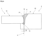
- FIG. 4 illustrates a weld 6 in a butt joint formed by the main and auxiliary beams 41, 51.
- FIG. 4 shows the situation after the melting, while FIGS. 3A and 3B above show the situation prior to the melting.
- the portion including the step 73 is melted by the main and auxiliary beams 41, 51.
- the molten metal moves toward the first member 1 and enters the gap 72, thereby filling the gap 72, including the space expanded by the chamfered portion 14, to form the weld 6 in the butt j oint.
- the gap 72 is filled by the melting of both the first and second members 1, 2.
- the molten amount of the second member 2 filling the gap 72 is greater than that of the first member 1.
- the above welding method in which the focal point of the main beam 41 is shifted by a predetermined amount in the direction toward the face 22, which is the face closer to the irradiation head 4, of the second member 2 for welding rather than locating the focal point at the butting plane 3, allows for forming the weld 6 by filling the gap 72, if any.
- this method eliminates the need for beveling and tapering processes when welding the first and second members 1, 2 in a butt joint.
- the second embodiment includes common features to those in the first embodiment described above. Accordingly, the same reference numerals are used in the drawings to identify such common features. However, descriptions of such features may be omitted from the description.
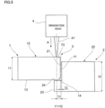
- FIG. 5 illustrates a welding method according to the second embodiment, corresponding to FIG. 1 illustrating the first embodiment.
- the second embodiment shown in FIG. 5 illustrates a welding method of welding the first and second members 1, 2 in a butt joint.
- the irradiation head 4 is the same as that in the first embodiment (see FIG. 1 ) in that it delivers the high-energy beam 41.
- the thickness t1 of the first member 1 is smaller than the thickness t2 of the second member 2 (t1 ⁇ t2).
- the face 12 of the first member 1 is located closer to the irradiation head 4 than the face 22 of the second member 2 is.
- the high-energy beam 41 from the irradiation head 4 is focused on the face 12 of the first member 1, which is the face closer to the irradiation head 4, and the focal point of the high-energy beam 41 is shifted in the direction toward the face 12 of the first member 1, which is the face closer to the irradiation head 4, rather than in the direction toward the face 22 of the second member 2, which is the face farther from the irradiation head 4.
- the second embodiment differs from the first embodiment (see FIG. 1 ) in these respects.
- first and second members 1, 2 may be planar or cylindrical.
- FIGS. 6A and 6B an application example according to the second embodiment is described.
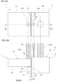
- FIGS. 6A and 6B illustrate an application example using multiple high-energy beams 41, 51, where FIG. 6A illustrates the first and second members 1, 2 as viewed from the high-energy beams 41, 51, and FIG. 6B illustrates a cross-section along line VIb-Vib in FIG. 6A.
- FIGS. 6A and 6B correspond to FIGS. 3A and 3B illustrating the first embodiment.
- the application example according to the second embodiment shown in FIG. 6A is similar to the first embodiment in that the high-energy beam 51 is provided around the high-energy beam 41 and moves with the high-energy beam 41 in the welding direction B.
- this application example differs from the first embodiment in that the main beam 41 is delivered onto the face 12 of the first member 1 and the auxiliary beam 51 is delivered onto both the face 12 of the first member 1 and the face 22 of the second member 2.
- auxiliary beam 51 is delivered onto the face 12 of the first member 1 than on the face 22 of the second member 2 due to the main beam 41 being shifted.
- this application example differs from the first embodiment in that the high-energy beams 41, 51 with higher energy can be delivered onto the first member 1 than on the second member 2.
- FIG. 7 illustrates a weld 6 in a butt joint formed by the main and auxiliary beams 41, 51, corresponding to FIG. 4 illustrating the first embodiment.
- the portion including the step 73 is melted by the main and auxiliary beams 41, 51.
- the molten metal moves toward the second member 2 and enters the gap 72, thereby filling the gap 72, including the space expanded by the chamfered portion 14, to form the weld 6 in the butt joint.
- the third embodiment includes common features to those in the first embodiment described above. Accordingly, the same reference numerals are used in the drawings to identify such common features. However, descriptions of such features may be omitted from the description.
- FIG. 8 illustrates a welding method according to the third embodiment, corresponding to FIG. 1 illustrating the first embodiment.
- the third embodiment shown in FIG. 8 illustrates a welding method of welding the first and second members 1, 2 in a butt joint.
- the irradiation head 4 is the same as that in the first embodiment (see FIG. 1 ) in that it delivers the high-energy beam 41.
- the thickness t1 of the first member 1 is greater than the thickness t2 of the second member 2 (11 > t2).
- the face 12 of the first member 1 is located closer to the irradiation head 4 than the face 22 of the second member 2 is.
- the high-energy beam 41 from the irradiation head 4 is focused on the face 12 of the first member 1, which is the face closer to the irradiation head 4, rather than on the face 22 of the second member 2 farther from the irradiation head 4.
- the focal point of the high-energy beam 41 is shifted in the direction toward the face 12 of the first member 1, which is the face closer to the irradiation head 4, rather than in the direction toward the face 22 of the second member 2, which is the face farther from the irradiation head 4.
- the third embodiment differs from the first embodiment (see FIG. 1 ) and is similar to the second embodiment (see FIG. 5 ).
- application examples according to the third embodiment may employ similar configurations as those in the application examples according to the first and second embodiments (see FIGS. 3A-3B and 6A-6B ).
- FIGS. 9A and 9B illustrate the high-energy beams 41, 51, where FIG. 9A is a plan view of the high-energy beams 41, 51 according to the first and second embodiments, and FIG. 9B is a plan view of high-energy beams 41, 51A, 51B according to a first variant.
- a single, circumferential high-energy beam 51 is provided to continuously surround the high-energy beam 41. This is the same as the application examples according to the first and second embodiments described above ( FIG. 3A and FIG. 6A ).
- the high-energy beam 41 is surrounded by two high-energy beams 51A, 51B.
- two high-energy beams 51A, 51B with different outer diameters are provided around the high-energy beam 41.
- the high-energy beam 51A has a larger diameter and the high-energy beam 51B has a smaller diameter.
- the high-energy beam 51B is located between the high-energy beam 41 and the high-energy beam 51A.
- the high-energy beams delivered from the high-energy beams 51A, 51B may have the same width or different widths.
- the first variant is applicable to any of the first, second, and third embodiments described above.
- FIGS. 10A and 10B illustrate a welding method according to a second variant, where FIG. 10A illustrates the first and second members 1, 2 as viewed from the high-energy beams 41, 51, and FIG. 10B illustrates a cross-section along line Xb-Xb in FIG. 10A .
- the high-energy beam 41 is shifted in the direction toward the face 22 of the second member 2, which is the face closer to the irradiation head 4, by a predetermined amount 71 with respect to the butting plane 3. This feature is common to the first embodiment described above.
- high-energy beams 51C, 51D are provided in addition to the high-energy beam 41.
- the high-energy beams 51C, 51D are located with the high-energy beam 41 therebetween.
- the high-energy beam 41 is located between the high-energy beams 51C, 51D.
- the high-energy beam 51C is delivered onto the face 12 of the first member 1, while the high-energy beam 51D is delivered onto the face 22 of the second member 2.
- the high-energy beams 51C, 51D are not of a donut shape but of a circular shape having the center portion.
- the irradiation zones of the high-energy beams 51C, 51D have different outer diameters; the irradiation zone of the high-energy beam 51D is larger in diameter and wider than that of the high-energy beam 51C. Accordingly, more high-energy is input to the second member 2 with the step 73, resulting in an increased molten amount of the second member 2.
- the second member which is the thicker one, can be irradiated with the energy with higher power or wider range.
- the high-energy beam 41 and the high-energy beams 51, 51C-51D are illustrated as being delivered vertically to the faces 12, 22.
- this is not limiting. That is, in addition to welding methods using a vertical irradiation, an oblique irradiation may also be employed.
- FIGS. 11A-11C illustrate welding conditions, where FIG. 11A illustrates the first and second members 1, 2 as viewed from the irradiation head 4, FIG. 11B illustrates a cross-section along line XIb-XIb in FIG. 11A, and FIG. 11C illustrates a weld 6 made using keyhole welding.
- FIG. 11A corresponds to FIG. 5
- FIG. 11B corresponds to FIG. 6B
- FIG. 11C corresponds to FIG. 7 .
- the first member 1, which is the thinner one of the first and second members 1,2, has a thickness t
- its chamfered portion 14 has a chamfer length c
- the main beam 41 is located at the position corresponding to a correction amount p, as shown in FIG. 11B .
- the main beam 41 has a beam power w.
- the penetration depth Y shown in FIG. 11C can then be calculated by the following formula.
- Y 0.648t + 2.979p - 0.001s + 0.004p(s - 2000) + 0.001c(s - 2000) +0.844p(t - 7.7) + 0.25w - 0.231c + 0.778p(c - 2) + 3.789
- t is the thickness
- p is the correction amount
- s is the speed
- w the beam power
- c is the chamfer length.
- a gap margin range GAP which represents allowable values of the gap 72 when the gap 72 is filled by the melt of the molten first and second members 1, 2, can be calculated by the following formula.
- the filled weld 6 (see FIG. 4 , for example) is unlikely to be formed.
- GAP ⁇ D 2 8 t ⁇ where D is the focus diameter, and t is the thickness.
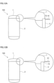
- FIGS. 12A and 12B illustrate applications of the present embodiments to a pressure vessel 100, each showing an example of the pressure vessel 100 with dividing walls of different thicknesses.
- the pressure vessel 100 is configured as having a body pipe and a top plate, and for convenience of illustration, the top plate and the body pipe are referred to hereinafter as the first member 1 and the second member 2, respectively.
- the second member 2 has a larger outer diameter than the first member 1, so that the second member 2 includes the step 73.
- the welding method according to the first embodiment described above is applied. That is, the focal point of the high-energy beam 41 is shifted toward the second member 2. This allows for making the pressure vessel 100 using keyhole welding.
- the second member 2 has a smaller outer diameter than the first member 1, so that the first member 1 includes the step 73.
- the welding method according to the second embodiment described above is applied. That is, the focal point of the high-energy beam 41 is shifted toward the first member 1. This allows for making the pressure vessel 100 using keyhole welding.
Landscapes
- Physics & Mathematics (AREA)
- Optics & Photonics (AREA)
- Engineering & Computer Science (AREA)
- Mechanical Engineering (AREA)
- Plasma & Fusion (AREA)
- Laser Beam Processing (AREA)
- Welding Or Cutting Using Electron Beams (AREA)
Abstract
Description
- The present disclosure relates to a welding method and a method for manufacturing pressure vessel.
- For example,
Patent Literature 1 discloses a method for joining by welding thickwalled metal workpieces joined by at least two welding layers and having a wall thickness of greater than 6 mm, the method including providing seam preparations in the cross-sections of the welded portions for a full-area connection before welding in weld zones for the at least two welding layers. - Patent Literature 1:
Japanese Patent No. 5519494 - When welding workpieces with different thicknesses in a butt joint, tapering the edges of the workpieces in conjunction with beveling them requires precision control of the machined areas, making it difficult to reduce manufacturing costs. In addition, if any postprocessing is performed to improve appearance, such as additional welding or cutting of the welded portions, it becomes even more difficult to reduce manufacturing costs.
- It is an object of the present disclosure to reduce manufacturing costs when welding workpieces with different thicknesses in a butt joint.
- The present disclosure provides a welding method for welding a first member and a second member with different thicknesses in a butt joint. The method includes: correcting a focal point of a high-energy beam for keyhole welding from a butting plane between a face of the first member and a face of the second member toward one of the faces by a predetermined amount for the welding, the one of the faces having a step created by butting together the face of the first member and the face of the second member and being closer to an irradiation head of the high-energy beam. This welding method can reduce manufacturing costs when welding workpieces with different thicknesses in a butt joint.
- The predetermined amount may be less than or equal to 90% of a focus diameter at the focal point. This can increase the molten amount of the member including the face closer to the irradiation head.
- The predetermined amount may be less than or equal to 50% of a focus diameter at the focal point. This can increase the molten amount of the member including the face closer to the irradiation head.
- A molten amount by the keyhole welding may be greater on one of the faces of the first member and the second member than the other, the one being closer to the irradiation head than the other. This more reliably ensures that the gap between the first member and the second member is filled.
- The keyhole welding may be performed by a main laser having the focal point to be corrected and an auxiliary laser provided around the main laser. This allows for melting over a wider area.
- The keyhole welding may be laser welding or electron beam welding. This allows for welding with high energy.
- Welding conditions for a penetration depth Y of the keyhole welding may be expressed by the following formula:
Y = 0.648t + 2.979p - 0.001s + 0.004p(s - 2000) + 0.001c(s - 2000) +0.844p(t - 7.7) + 0.25w - 0.231c + 0.778p(c - 2) + 3.789 - A gap margin range GAP between the first member and the second member may be expressed by the following formula:

- In another aspect, the present disclosure provides a method for manufacturing a pressure vessel. The method includes: making a pressure vessel by keyhole welding using the welding method described above.
-
-
FIG. 1 illustrates a welding method according to a first embodiment. -
FIGS. 2A to 2C illustrate correction amounts, whereFIG. 2A illustrates a case where the correction amount is 0%,FIG. 2B illustrates a case where the correction amount is 50%, andFIG. 2C illustrates a case where the correction amount is 90%. -
FIGS. 3A and 3B illustrate an application example using multiple high-energy beams, whereFIG. 3A illustrates first and second members as viewed from multiple high-energy beams, andFIG. 3B illustrates a cross-section along line IIIb-IIIb inFIG. 3A . -
FIG. 4 illustrates a weld in a butt joint formed by main and auxiliary beams. -
FIG. 5 illustrates a welding method according to a second embodiment. -
FIGS. 6A and 6B illustrate an application example using multiple high-energy beams, whereFIG. 6A illustrates the first and second members as viewed from multiple high-energy beams, andFIG. 6B illustrates a cross-section along line VIb-VIb inFIG. 6A . -
FIG. 7 illustrates a weld in a butt joint formed by main and auxiliary beams. -
FIG. 8 illustrates a welding method according to a third embodiment. -
FIGS. 9A and 9B illustrate irradiation heads, whereFIG. 9A illustrates the irradiation head according to the first and second embodiments, andFIG. 9B illustrates an irradiation head according to a first variant. -
FIGS. 10A and 10B illustrate a welding method according to a second variant, whereFIG. 10A illustrates the first and second members as viewed from the irradiation head, andFIG. 10B illustrates a cross-section along line Xb-Xb inFIG. 10A . -
FIGS. 11A-11C illustrate welding conditions, whereFIG. 11A illustrates the first and second members as viewed from the irradiation head,FIG. 11B illustrates a cross-section along line XIb-XIb inFIG. 11A, and FIG. 11C illustrates a weld made using keyhole welding. -
FIGS. 12A and 12B illustrate applications of the present embodiments to a pressure vessel, each showing an example of the pressure vessel with dividing walls of different thicknesses. - Exemplary embodiments are now detailed with reference to the appended drawings.
-
FIG. 1 illustrates a welding method according to a first embodiment. - The first embodiment shown in
FIG. 1 relates to a case of welding afirst member 1 and asecond member 2 in a butt j oint. In this case, the welding is keyhole welding, which uses high energy densities to generate metal vapor and advantageously create cavities on the surface. - An
irradiation head 4 for laser welding is located opposite anend face 11 of thefirst member 1 and anend face 21 of thesecond member 2. Theirradiation head 4 includes a focusing lens (not shown) that focuses the laser light output from anoscillator 8 through anoptical fiber 81 and delivers a high-energy beam 41 for the keyhole welding in the irradiation direction A. - To further illustrate, an
imaginary butting plane 3, indicated by a dash-dotted line, is located at the interface between theend face 11 of thefirst member 1 and theend face 21 of thesecond member 2. In other words, the buttingplane 3 is located between theend face 11 of thefirst member 1 and theend face 21 of thesecond member 2. - The
first member 1 has a thickness t1 and thesecond member 2 has a thickness t2. The values of thethicknesses 11, t2 are not the same, so that there is a thickness difference between the first andsecond members first member 1 is smaller than the thickness t2 of the second member 2 (t1 < t2). - The
second member 2 includes astep 23 extending toward thefirst member 1. Thestep 23 includes abottom face 24 facing aninner face 13 of thefirst member 1. Thus, thestep 23 includes a portion with a generally L-shaped cross-section defined by theend face 21 and thebottom face 24. Theinner face 13 as referred to herein is opposite aface 12 of thefirst member 1. A chamferedportion 14 is formed at a connection between theend face 11 and theinner face 13 of thefirst member 1. - To further illustrate, the
step 23 of thesecond member 2 is situated away from aface 22 of thesecond member 2 with respect to the irradiation direction A. - The first and
second members - Now, a description is given of the positional relationship between the
face 12 of thefirst member 1 and theface 22 of thesecond member 2 with respect to theirradiation head 4 when thefirst member 1 and thesecond member 2 are butted together. - The
face 12 of thefirst member 1 and theface 22 of thesecond member 2 are at different positions relative to theirradiation head 4 with respect to the irradiation direction A. In other words, butting together theend face 11 of thefirst member 1 and theend face 21 of thesecond member 2 creates astep 73 in thesecond member 2. Such astep 73 defines a corner that connects theend face 21 and theface 22 of thesecond member 2. - More specifically, in the first embodiment, the
face 22 of thesecond member 2 is closer to theirradiation head 4 than theface 12 of thefirst member 1 is. In other words, theface 22 of the thickersecond member 2 is closer to theirradiation head 4, and theface 12 of the thinnerfirst member 1 is farther from theirradiation head 4. - The high-
energy beam 41 from theirradiation head 4 is focused on theface 22 of thesecond member 2, which is closer to theirradiation head 4, rather than on theface 12 of thefirst member 2, which is farther from theirradiation head 4. - The focal point of such a high-
energy beam 41 is not located on the buttingplane 3 but is shifted toward theface 22 of thesecond member 2, which is the face closer to theirradiation head 4. - The amount of shift of the focal point is a
predetermined amount 71. Such an amount of shift is used to correct the focal point of the high-energy beam 41 from the position of the buttingplane 3 toward thesecond member 2 in order to accommodate the step created by the first andsecond members - Thus, in the first embodiment, the focal point of the high-
energy beam 41 for keyhole welding is shifted by thepredetermined amount 71 from the buttingplane 3 toward theface 22 of thesecond member 2 for the welding. - A
gap 72 at the interface between theend face 11 of thefirst member 1 and theend face 21 of thesecond member 2 is within a predetermined range. Such a range is referred to as a gap margin, which is detailed below. - Note that
FIG. 1 shows an example schematic configuration in which keyhole welding is performed by laser welding using high-power laser light. Instead of the laser welding described above, which is one of beam welding techniques, keyhole welding may be performed by electron beam welding. - Such electron beam welding, for example, uses the high energy of accelerated electrons released from a vacuum tube. An example schematic configuration for electron beam welding includes an electron gun with a filament (negative electrode), an anode (positive electrode), and a Wehnelt electrode (grid). Under high vacuum, thermoelectrons released from the tip end of the filament heated by a heating power supply are restricted by the Wehnelt electrode and accelerated by the anode. The thermoelectrons are then focused by an electromagnetic focusing coil utilizing the effect of the electromagnetic field, resulting in the generation of an electron beam, which is the high-
energy beam 41. -
FIGS. 2A to 2C illustrate the correction amounts, whereFIG. 2A illustrates a case where the correction amount is 0%,FIG. 2B illustrates a case where the correction amount is 50%, andFIG. 2C illustrates a case where the correction amount is 90%. - In the example shown in
FIG. 2A , the focal point of the high-energy beam 41 is located at the buttingplane 3 and is thus not corrected. More specifically, the high-energy beam 41 (seeFIG. 1 ) is focused at afocus region 91 centered around thefocus position 90, with afocus diameter 70. - In the example shown in
FIG. 2B , the focal point of the high-energy beam 41 is shifted by thepredetermined amount 71 from the buttingplane 3 toward thesecond member 2, where the correction amount is 50%. More specifically, inFIG. 2B , the high-energy beam 41 is focused at afocus region 92 centered around thefocus position 90, with the focus diameter being the same as that inFIG. 2A . - For the purpose of illustrating the correction amount,
FIG. 2B shows thefocus region 91 shown inFIG. 2A in dashed lines, in contrast to thefocus region 92 shifted by thepredetermined amount 71. Thepredetermined amount 71 is a percentage of thefocus diameter 70 and is 50% as the correction amount. In other words, thefocus region 92 inFIG. 2B corresponds to thefocus region 91 inFIG. 2A shifted by half the amount of thefocus diameter 70 in the direction toward thesecond member 2. - In the example shown in
FIG. 2C , the focal point of the high-energy beam 41 is shifted by thepredetermined amount 71 from the buttingplane 3 toward thesecond member 2, where the focal point is further shifted in the direction toward thesecond member 2 than the example ofFIG. 2B , with the correction amount being 90%. More specifically, inFIG. 2C , the high-energy beam 41 is focused at afocus region 93 centered around thefocus position 90 on theface 22 of thesecond member 2, with the focus diameter being the same as those inFIGS. 2A and 2B . -
FIG. 2C also shows thefocus region 91 shown inFIG. 2A in dashed lines, in contrast to thefocus region 93 shifted by thepredetermined amount 71. Thefocus region 93 inFIG. 2C corresponds to thefocus region 91 shifted by 90% of thefocus diameter 70 of thefocus region 91 in the direction toward thesecond member 2. - As the
predetermined amount 71 as the correction amount is increased in this manner, the amount of high-energy beam 41 delivered onto theface 22 of thesecond member 2 increases, which in turn leads to a wider molten region in thesecond member 2 and an increased molten amount of thesecond member 2 including the step 73 (seeFIG. 1 ). Thepredetermined amount 71 is less than or equal to 90% of the focus diameter at the focal point. - On the other hand, if the
predetermined amount 71 as the correction amount is excessively large, the amount of high-energy beam 41 delivered onto theface 12 of thefirst member 1 will decrease, which in turn leads to a reduced molten amount of thefirst member 1 and may thus reduce the weld strength. Therefore, thepredetermined amount 71 is more preferably 50% or less. - Referring now to
FIGS. 3A and 3B , an application example according to the first embodiment is described. -
FIGS. 3A and 3B illustrate an application example using multiple high-energy beams FIG. 3A illustrates the first andsecond members energy beams FIG. 3B illustrates a cross-section along line IIIb-IIIb inFIG. 3A. FIG. 3B corresponds toFIG. 1 . A dash-dotted line representing the buttingplane 3 is shown acrossFIGS. 3A and 3B to clarify the positional correspondences. - As shown in
FIG. 3A , in this application example according to the first embodiment, an additional high-energy beam 51 is provided around the high-energy beam 41. - The high-
energy beams - As shown in
FIG. 3B , theirradiation head 4 delivers the high-energy beam 41 and also delivers the additional high-energy beam 51. The irradiation zone of the high-energy beam 51 is provided around the high-energy beam 41 excluding the irradiation region of the high-energy beam 41 and is of a so-called donut shape. - The high-
energy beam 41 and the high-energy beam 51 from theirradiation head 4 may be referred to hereinafter as themain beam 41 and theauxiliary beam 51, respectively. Themain beam 41 has a higher power than theauxiliary beam 51. - As shown in
FIG. 3B , themain beam 41 is delivered onto theface 22 of thesecond member 2, and theauxiliary beam 51 is delivered onto both theface 12 of thefirst member 1 and theface 22 of thesecond member 2. A more amount of theauxiliary beam 51 is delivered onto theface 22 of thesecond member 2 than on theface 12 of thefirst member 1 due to theirradiation head 4 being shifted. - By focusing the high-
energy beams face 22 of thesecond member 2, the high-energy beams second member 2 than on thefirst member 1. -
FIG. 4 illustrates aweld 6 in a butt joint formed by the main andauxiliary beams FIG. 4 shows the situation after the melting, whileFIGS. 3A and 3B above show the situation prior to the melting. - As shown in
FIG. 4 , the portion including thestep 73 is melted by the main andauxiliary beams first member 1 and enters thegap 72, thereby filling thegap 72, including the space expanded by the chamferedportion 14, to form theweld 6 in the butt j oint. Thegap 72 is filled by the melting of both the first andsecond members second member 2 filling thegap 72 is greater than that of thefirst member 1. - The above welding method, in which the focal point of the
main beam 41 is shifted by a predetermined amount in the direction toward theface 22, which is the face closer to theirradiation head 4, of thesecond member 2 for welding rather than locating the focal point at the buttingplane 3, allows for forming theweld 6 by filling thegap 72, if any. In addition, this method eliminates the need for beveling and tapering processes when welding the first andsecond members - While an example of keyhole welding using the main and
auxiliary beams main beam 41 alone without theauxiliary beam 51, so that the illustration and detailed description of such welding is omitted. - A second embodiment is now described. The second embodiment includes common features to those in the first embodiment described above. Accordingly, the same reference numerals are used in the drawings to identify such common features. However, descriptions of such features may be omitted from the description.
-
FIG. 5 illustrates a welding method according to the second embodiment, corresponding toFIG. 1 illustrating the first embodiment. - The second embodiment shown in
FIG. 5 illustrates a welding method of welding the first andsecond members irradiation head 4 is the same as that in the first embodiment (seeFIG. 1 ) in that it delivers the high-energy beam 41. - Similarly to the first embodiment (see
FIG. 1 ), the thickness t1 of thefirst member 1 is smaller than the thickness t2 of the second member 2 (t1 < t2). - On the other hand, unlike the first embodiment (see
FIG. 1 ), in which theface 22 of thesecond member 2 is located closer to the irradiation head 4 (seeFIG. 1 ), theface 12 of thefirst member 1 is located closer to theirradiation head 4 than theface 22 of thesecond member 2 is. - In the second embodiment, the high-
energy beam 41 from theirradiation head 4 is focused on theface 12 of thefirst member 1, which is the face closer to theirradiation head 4, and the focal point of the high-energy beam 41 is shifted in the direction toward theface 12 of thefirst member 1, which is the face closer to theirradiation head 4, rather than in the direction toward theface 22 of thesecond member 2, which is the face farther from theirradiation head 4. The second embodiment differs from the first embodiment (seeFIG. 1 ) in these respects. - Similarly to the first embodiment, the first and
second members - Referring now to
FIGS. 6A and 6B , an application example according to the second embodiment is described. -
FIGS. 6A and 6B illustrate an application example using multiple high-energy beams FIG. 6A illustrates the first andsecond members energy beams FIG. 6B illustrates a cross-section along line VIb-Vib inFIG. 6A. FIGS. 6A and 6B correspond toFIGS. 3A and 3B illustrating the first embodiment. - The application example according to the second embodiment shown in
FIG. 6A is similar to the first embodiment in that the high-energy beam 51 is provided around the high-energy beam 41 and moves with the high-energy beam 41 in the welding direction B. - As shown in
FIG. 6B , this application example differs from the first embodiment in that themain beam 41 is delivered onto theface 12 of thefirst member 1 and theauxiliary beam 51 is delivered onto both theface 12 of thefirst member 1 and theface 22 of thesecond member 2. - Another distinction from the first embodiment is that a more amount of the
auxiliary beam 51 is delivered onto theface 12 of thefirst member 1 than on theface 22 of thesecond member 2 due to themain beam 41 being shifted. - As such, this application example differs from the first embodiment in that the high-
energy beams first member 1 than on thesecond member 2. -
FIG. 7 illustrates aweld 6 in a butt joint formed by the main andauxiliary beams FIG. 4 illustrating the first embodiment. - As shown in
FIG. 7 , the portion including thestep 73 is melted by the main andauxiliary beams second member 2 and enters thegap 72, thereby filling thegap 72, including the space expanded by the chamferedportion 14, to form theweld 6 in the butt joint. - A third embodiment is now described. The third embodiment includes common features to those in the first embodiment described above. Accordingly, the same reference numerals are used in the drawings to identify such common features. However, descriptions of such features may be omitted from the description.
-
FIG. 8 illustrates a welding method according to the third embodiment, corresponding toFIG. 1 illustrating the first embodiment. - The third embodiment shown in
FIG. 8 illustrates a welding method of welding the first andsecond members irradiation head 4 is the same as that in the first embodiment (seeFIG. 1 ) in that it delivers the high-energy beam 41. - Unlike both the first embodiment (see
FIG. 1 ) and the second embodiment (seeFIG. 5 ), the thickness t1 of thefirst member 1 is greater than the thickness t2 of the second member 2 (11 > t2). - On the other hand, unlike the first embodiment (see
FIG. 1 ) and similarly to the second embodiment (seeFIG. 5 ), theface 12 of thefirst member 1 is located closer to theirradiation head 4 than theface 22 of thesecond member 2 is. - In the third embodiment, the high-
energy beam 41 from theirradiation head 4 is focused on theface 12 of thefirst member 1, which is the face closer to theirradiation head 4, rather than on theface 22 of thesecond member 2 farther from theirradiation head 4. Additionally, in the third embodiment, the focal point of the high-energy beam 41 is shifted in the direction toward theface 12 of thefirst member 1, which is the face closer to theirradiation head 4, rather than in the direction toward theface 22 of thesecond member 2, which is the face farther from theirradiation head 4. In these respects, the third embodiment differs from the first embodiment (seeFIG. 1 ) and is similar to the second embodiment (seeFIG. 5 ). - Although not illustrated and described herein, application examples according to the third embodiment may employ similar configurations as those in the application examples according to the first and second embodiments (see
FIGS. 3A-3B and6A-6B ). -
FIGS. 9A and 9B illustrate the high-energy beams FIG. 9A is a plan view of the high-energy beams FIG. 9B is a plan view of high-energy beams - As shown in
FIG. 9A , a single, circumferential high-energy beam 51 is provided to continuously surround the high-energy beam 41. This is the same as the application examples according to the first and second embodiments described above (FIG. 3A andFIG. 6A ). - In the first variant shown in
FIG. 9B , unlike the case ofFIG. 9A , the high-energy beam 41 is surrounded by two high-energy beams energy beams energy beam 41. The high-energy beam 51A has a larger diameter and the high-energy beam 51B has a smaller diameter. In other words, the high-energy beam 51B is located between the high-energy beam 41 and the high-energy beam 51A. - The high-energy beams delivered from the high-
energy beams -
FIGS. 10A and 10B illustrate a welding method according to a second variant, whereFIG. 10A illustrates the first andsecond members energy beams FIG. 10B illustrates a cross-section along line Xb-Xb inFIG. 10A . - In the second variant shown in
FIGS. 10A and 10B , the high-energy beam 41 is shifted in the direction toward theface 22 of thesecond member 2, which is the face closer to theirradiation head 4, by apredetermined amount 71 with respect to the buttingplane 3. This feature is common to the first embodiment described above. - In the second variant, on the other hand, high-
energy beams energy beam 41. The high-energy beams energy beam 41 therebetween. In other words, the high-energy beam 41 is located between the high-energy beams - The high-
energy beam 51C is delivered onto theface 12 of thefirst member 1, while the high-energy beam 51D is delivered onto theface 22 of thesecond member 2. - To further illustrate, unlike the
auxiliary beam 51 shown in the application examples described above (seeFIG. 3B andFIG. 6B ), the high-energy beams - The irradiation zones of the high-
energy beams energy beam 51D is larger in diameter and wider than that of the high-energy beam 51C. Accordingly, more high-energy is input to thesecond member 2 with thestep 73, resulting in an increased molten amount of thesecond member 2. - Thus, according to the second variant, the second member, which is the thicker one, can be irradiated with the energy with higher power or wider range.
- In the first and other embodiments described above, the high-
energy beam 41 and the high-energy beams faces -
FIGS. 11A-11C illustrate welding conditions, whereFIG. 11A illustrates the first andsecond members irradiation head 4,FIG. 11B illustrates a cross-section along line XIb-XIb inFIG. 11A, and FIG. 11C illustrates aweld 6 made using keyhole welding. For example,FIG. 11A corresponds toFIG. 5 ,FIG. 11B corresponds toFIG. 6B , andFIG. 11C corresponds toFIG. 7 . - Assume that the
first member 1, which is the thinner one of the first andsecond members portion 14 has a chamfer length c, and themain beam 41 is located at the position corresponding to a correction amount p, as shown inFIG. 11B . Also, assume that themain beam 41 has a beam power w. - Also, assume that the
main beam 41 moves at a speed s in the welding direction B during welding, as shown inFIG. 11A . - The penetration depth Y shown in
FIG. 11C can then be calculated by the following formula.Y = 0.648t + 2.979p - 0.001s + 0.004p(s - 2000) + 0.001c(s - 2000) +0.844p(t - 7.7) + 0.25w - 0.231c + 0.778p(c - 2) + 3.789 - Also, assume that the
main beam 41 has a focus diameter D, as shown inFIG. 11B . Then, a gap margin range GAP, which represents allowable values of thegap 72 when thegap 72 is filled by the melt of the molten first andsecond members - If the
gap 72 is greater than the gap margin range GAP, the filled weld 6 (seeFIG. 4 , for example) is unlikely to be formed.
-
FIGS. 12A and 12B illustrate applications of the present embodiments to apressure vessel 100, each showing an example of thepressure vessel 100 with dividing walls of different thicknesses. Thepressure vessel 100 is configured as having a body pipe and a top plate, and for convenience of illustration, the top plate and the body pipe are referred to hereinafter as thefirst member 1 and thesecond member 2, respectively. - In the
pressure vessel 100 shown inFIG. 12A , thesecond member 2 has a larger outer diameter than thefirst member 1, so that thesecond member 2 includes thestep 73. Thus, the welding method according to the first embodiment described above (see, for example,FIG. 1 ) is applied. That is, the focal point of the high-energy beam 41 is shifted toward thesecond member 2. This allows for making thepressure vessel 100 using keyhole welding. - In the
pressure vessel 100 shown inFIG. 12B , thesecond member 2 has a smaller outer diameter than thefirst member 1, so that thefirst member 1 includes thestep 73. Thus, the welding method according to the second embodiment described above (see, for example,FIG. 5 ) is applied. That is, the focal point of the high-energy beam 41 is shifted toward thefirst member 1. This allows for making thepressure vessel 100 using keyhole welding. - While some embodiments have been described above, it will be understood that various modifications may be made to the embodiments and details without departing from the spirit and scope of the appended claims.
-
- 1 First member
- 11, 21 End surface
- 12, 22 Face
- 2 Second member
- 3 Butting plane
- 4, 5 Irradiation head
- 41, 51 High-energy beam
- 6 Weld
- 70 Focus diameter
- 73 Step
- 71 Predetermined amount
- 100 Pressure vessel
Claims (9)
- A welding method for welding a first member and a second member with different thicknesses in a butt joint, the method comprising:
correcting a focal point of a high-energy beam for keyhole welding from a butting plane between a face of the first member and a face of the second member toward one of the faces by a predetermined amount for the welding, the one of the faces having a step created by butting together the face of the first member and the face of the second member and being closer to an irradiation head of the high-energy beam. - The welding method according to claim 1, wherein the predetermined amount is less than or equal to 90% of a focus diameter at the focal point.
- The welding method according to claim 2, wherein the predetermined amount is less than or equal to 50% of the focus diameter at the focal point.
- The welding method according to claim 1, wherein a molten amount by the keyhole welding is greater on one of the faces of the first member and the second member than the other, the one being closer to the irradiation head than the other.
- The welding method according to claim 1, wherein the keyhole welding is performed by a main laser having the focal point to be corrected and an auxiliary laser provided around the main laser.
- The welding method according to claim 1, wherein the keyhole welding is laser welding or electron beam welding.
- The welding method according to claim 1, wherein welding conditions for a penetration depth Y of the keyhole welding are expressed by the following formula:
Y = 0.648t + 2.979p - 0.001s + 0.004p(s - 2000) + 0.001c(s - 2000) +0.844p(t - 7.7) + 0.25w - 0.231c + 0.778p(c - 2) + 3.789 - The welding method according to claim 1, wherein a gap margin range GAP between the first member and the second member is expressed by the following formula:

- A method for manufacturing a pressure vessel, the method comprising:
making a pressure vessel by keyhole welding using the welding method according to claim 1.
Applications Claiming Priority (2)
| Application Number | Priority Date | Filing Date | Title |
|---|---|---|---|
| JP2023058411A JP7667480B2 (en) | 2023-03-31 | 2023-03-31 | Welding method and manufacturing method for pressure vessel |
| PCT/JP2024/011240 WO2024203819A1 (en) | 2023-03-31 | 2024-03-22 | Welding method and method for manufacturing pressure container |
Publications (2)
| Publication Number | Publication Date |
|---|---|
| EP4464453A1 true EP4464453A1 (en) | 2024-11-20 |
| EP4464453A4 EP4464453A4 (en) | 2025-05-07 |
Family
ID=91070322
Family Applications (1)
| Application Number | Title | Priority Date | Filing Date |
|---|---|---|---|
| EP24719448.3A Pending EP4464453A4 (en) | 2023-03-31 | 2024-03-22 | WELDING PROCESS AND PROCESS FOR MANUFACTURING A PRESSURE VESSEL |
Country Status (3)
| Country | Link |
|---|---|
| EP (1) | EP4464453A4 (en) |
| JP (1) | JP7667480B2 (en) |
| WO (1) | WO2024203819A1 (en) |
Family Cites Families (11)
| Publication number | Priority date | Publication date | Assignee | Title |
|---|---|---|---|---|
| JPH0313289A (en) * | 1989-06-09 | 1991-01-22 | Kawasaki Steel Corp | Method and device for laser welding for metallic belt or the like |
| JPH0557467A (en) * | 1991-09-05 | 1993-03-09 | Toyota Motor Corp | Laser welding method for stocks with different plate thickness |
| FR2694713B1 (en) * | 1992-08-14 | 1994-11-04 | Lorraine Laminage | Welding process for at least two sheets of different thicknesses. |
| JPH07132386A (en) * | 1993-11-11 | 1995-05-23 | Nissan Motor Co Ltd | Butt welding method for plates with different plate thickness |
| JP2750293B2 (en) * | 1994-09-26 | 1998-05-13 | トヨタ自動車株式会社 | Manufacturing method of molded article and molded article |
| CA2335546A1 (en) * | 1998-06-29 | 2000-01-06 | Automated Welding Systems Inc. | Method of laser welding tailored blanks |
| DE19948013A1 (en) * | 1999-10-06 | 2001-05-17 | Thyssenkrupp Stahl Ag | Joining metal sheet with beam welding involves inclining axis of weld beam guided along butt joint to surface of sheet towards thick sheet side to pass only through thick sheet |
| JP2006218497A (en) * | 2005-02-09 | 2006-08-24 | Nippon Steel Corp | Laser welding method for plate material |
| DE102008029724B4 (en) | 2007-06-26 | 2010-09-30 | V&M Deutschland Gmbh | Method for joining thick-walled metallic pieces by means of welding |
| JP5153368B2 (en) * | 2008-01-31 | 2013-02-27 | 日立Geニュークリア・エナジー株式会社 | T-type joint penetration welding method and penetration welded structure |
| JP7420768B2 (en) * | 2021-07-01 | 2024-01-23 | フタバ産業株式会社 | Method for manufacturing tailored blanks and manufacturing method for automobile parts |
-
2023
- 2023-03-31 JP JP2023058411A patent/JP7667480B2/en active Active
-
2024
- 2024-03-22 WO PCT/JP2024/011240 patent/WO2024203819A1/en not_active Ceased
- 2024-03-22 EP EP24719448.3A patent/EP4464453A4/en active Pending
Also Published As
| Publication number | Publication date |
|---|---|
| EP4464453A4 (en) | 2025-05-07 |
| JP2024145866A (en) | 2024-10-15 |
| WO2024203819A1 (en) | 2024-10-03 |
| JP7667480B2 (en) | 2025-04-23 |
Similar Documents
| Publication | Publication Date | Title |
|---|---|---|
| JP5609632B2 (en) | Laser lap welding method | |
| KR101554800B1 (en) | Method of manufacturing laser welded steel pipe | |
| US20220234139A1 (en) | Laser welding for corner joins of workpiece parts | |
| US20140124489A1 (en) | Hybrid Welding Method of Laser Welding and Arc Welding for T-Joint | |
| US20120211474A1 (en) | Laser lap welding method | |
| US11110547B2 (en) | Laser welding method | |
| US11786989B2 (en) | Method for splash-free welding, in particular using a solid-state laser | |
| EP0098306A1 (en) | Welding method using laser beam | |
| CN103476535B (en) | laser welding method | |
| JP5866790B2 (en) | Laser welded steel pipe manufacturing method | |
| US20140021176A1 (en) | Method of joining two components using a welding process | |
| WO2011102295A1 (en) | Welding method and superconducting accelerator | |
| KR20160013260A (en) | Method for manufacturing laser welded steel pipe | |
| JP5954009B2 (en) | Manufacturing method of welded steel pipe | |
| CN118695919A (en) | Method for laser welding of bipolar plates for fuel cells with a power density distribution in the region of a molten pool that varies over time and in cycles | |
| JP3767369B2 (en) | Method of lap welding of thin steel plates and welded thin steel plates | |
| JP7667480B2 (en) | Welding method and manufacturing method for pressure vessel | |
| CN113039037B (en) | Joining method | |
| JP2003001453A (en) | Combined heat source welding method | |
| CN114434009A (en) | Method for manufacturing bonded body | |
| KR940011261B1 (en) | Laser welding method for c-crt electron gun | |
| JP3767374B2 (en) | Butt welding method and welded thin steel plate | |
| US20230001510A1 (en) | Manufacturing method of tailored blank and manufacturing method of automobile part | |
| JP5803160B2 (en) | Laser welded steel pipe manufacturing method | |
| EP4609982A1 (en) | Thick steel plate assembly welded by laser welding and laser welding method thereof |
Legal Events
| Date | Code | Title | Description |
|---|---|---|---|
| STAA | Information on the status of an ep patent application or granted ep patent |
Free format text: STATUS: UNKNOWN |
|
| STAA | Information on the status of an ep patent application or granted ep patent |
Free format text: STATUS: THE INTERNATIONAL PUBLICATION HAS BEEN MADE |
|
| PUAI | Public reference made under article 153(3) epc to a published international application that has entered the european phase |
Free format text: ORIGINAL CODE: 0009012 |
|
| STAA | Information on the status of an ep patent application or granted ep patent |
Free format text: STATUS: REQUEST FOR EXAMINATION WAS MADE |
|
| 17P | Request for examination filed |
Effective date: 20240425 |
|
| AK | Designated contracting states |
Kind code of ref document: A1 Designated state(s): AL AT BE BG CH CY CZ DE DK EE ES FI FR GB GR HR HU IE IS IT LI LT LU LV MC ME MK MT NL NO PL PT RO RS SE SI SK SM TR |
|
| P01 | Opt-out of the competence of the unified patent court (upc) registered |
Free format text: CASE NUMBER: APP_1126/2025 Effective date: 20250108 |
|
| REG | Reference to a national code |
Ref country code: DE Ref legal event code: R079 Free format text: PREVIOUS MAIN CLASS: B23K0026210000 Ipc: B23K0015000000 |
|
| A4 | Supplementary search report drawn up and despatched |
Effective date: 20250403 |
|
| RIC1 | Information provided on ipc code assigned before grant |
Ipc: B23K 33/00 20060101ALI20250328BHEP Ipc: B23K 26/24 20140101ALI20250328BHEP Ipc: B23K 26/042 20140101ALI20250328BHEP Ipc: B23K 26/06 20140101ALI20250328BHEP Ipc: B23K 101/12 20060101ALI20250328BHEP Ipc: B23K 15/00 20060101AFI20250328BHEP |