EP4464431A1 - High-pressure washing device - Google Patents
High-pressure washing device Download PDFInfo
- Publication number
- EP4464431A1 EP4464431A1 EP23920287.2A EP23920287A EP4464431A1 EP 4464431 A1 EP4464431 A1 EP 4464431A1 EP 23920287 A EP23920287 A EP 23920287A EP 4464431 A1 EP4464431 A1 EP 4464431A1
- Authority
- EP
- European Patent Office
- Prior art keywords
- washing
- water
- pressure washer
- disposed
- tank
- Prior art date
- Legal status (The legal status is an assumption and is not a legal conclusion. Google has not performed a legal analysis and makes no representation as to the accuracy of the status listed.)
- Pending
Links
Images



Classifications
-
- B—PERFORMING OPERATIONS; TRANSPORTING
- B08—CLEANING
- B08B—CLEANING IN GENERAL; PREVENTION OF FOULING IN GENERAL
- B08B3/00—Cleaning by methods involving the use or presence of liquid or steam
- B08B3/02—Cleaning by the force of jets or sprays
-
- B—PERFORMING OPERATIONS; TRANSPORTING
- B05—SPRAYING OR ATOMISING IN GENERAL; APPLYING FLUENT MATERIALS TO SURFACES, IN GENERAL
- B05B—SPRAYING APPARATUS; ATOMISING APPARATUS; NOZZLES
- B05B13/00—Machines or plants for applying liquids or other fluent materials to surfaces of objects or other work by spraying, not covered by groups B05B1/00 - B05B11/00
- B05B13/06—Machines or plants for applying liquids or other fluent materials to surfaces of objects or other work by spraying, not covered by groups B05B1/00 - B05B11/00 specially designed for treating the inside of hollow bodies
- B05B13/0645—Machines or plants for applying liquids or other fluent materials to surfaces of objects or other work by spraying, not covered by groups B05B1/00 - B05B11/00 specially designed for treating the inside of hollow bodies the hollow bodies being rotated during treatment operation
- B05B13/0681—Machines or plants for applying liquids or other fluent materials to surfaces of objects or other work by spraying, not covered by groups B05B1/00 - B05B11/00 specially designed for treating the inside of hollow bodies the hollow bodies being rotated during treatment operation the hollow bodies comprising a closed end to be treated
-
- B—PERFORMING OPERATIONS; TRANSPORTING
- B05—SPRAYING OR ATOMISING IN GENERAL; APPLYING FLUENT MATERIALS TO SURFACES, IN GENERAL
- B05B—SPRAYING APPARATUS; ATOMISING APPARATUS; NOZZLES
- B05B14/00—Arrangements for collecting, re-using or eliminating excess spraying material
- B05B14/40—Arrangements for collecting, re-using or eliminating excess spraying material for use in spray booths
-
- B—PERFORMING OPERATIONS; TRANSPORTING
- B05—SPRAYING OR ATOMISING IN GENERAL; APPLYING FLUENT MATERIALS TO SURFACES, IN GENERAL
- B05B—SPRAYING APPARATUS; ATOMISING APPARATUS; NOZZLES
- B05B15/00—Details of spraying plant or spraying apparatus not otherwise provided for; Accessories
- B05B15/40—Filters located upstream of the spraying outlets
-
- B—PERFORMING OPERATIONS; TRANSPORTING
- B05—SPRAYING OR ATOMISING IN GENERAL; APPLYING FLUENT MATERIALS TO SURFACES, IN GENERAL
- B05B—SPRAYING APPARATUS; ATOMISING APPARATUS; NOZZLES
- B05B9/00—Spraying apparatus for discharge of liquids or other fluent material, without essentially mixing with gas or vapour
- B05B9/002—Spraying apparatus for discharge of liquids or other fluent material, without essentially mixing with gas or vapour incorporating means for heating or cooling, e.g. the material to be sprayed
-
- B—PERFORMING OPERATIONS; TRANSPORTING
- B08—CLEANING
- B08B—CLEANING IN GENERAL; PREVENTION OF FOULING IN GENERAL
- B08B11/00—Cleaning flexible or delicate articles by methods or apparatus specially adapted thereto
- B08B11/02—Devices for holding articles during cleaning
-
- B—PERFORMING OPERATIONS; TRANSPORTING
- B08—CLEANING
- B08B—CLEANING IN GENERAL; PREVENTION OF FOULING IN GENERAL
- B08B3/00—Cleaning by methods involving the use or presence of liquid or steam
- B08B3/04—Cleaning involving contact with liquid
- B08B3/10—Cleaning involving contact with liquid with additional treatment of the liquid or of the object being cleaned, e.g. by heat, by electricity or by vibration
- B08B3/106—Cleaning involving contact with liquid with additional treatment of the liquid or of the object being cleaned, e.g. by heat, by electricity or by vibration by boiling the liquid
-
- B—PERFORMING OPERATIONS; TRANSPORTING
- B05—SPRAYING OR ATOMISING IN GENERAL; APPLYING FLUENT MATERIALS TO SURFACES, IN GENERAL
- B05B—SPRAYING APPARATUS; ATOMISING APPARATUS; NOZZLES
- B05B1/00—Nozzles, spray heads or other outlets, with or without auxiliary devices such as valves, heating means
- B05B1/14—Nozzles, spray heads or other outlets, with or without auxiliary devices such as valves, heating means with multiple outlet openings; with strainers in or outside the outlet opening
- B05B1/20—Perforated pipes or troughs, e.g. spray booms; Outlet elements therefor
- B05B1/202—Perforated pipes or troughs, e.g. spray booms; Outlet elements therefor comprising inserted outlet elements
-
- B—PERFORMING OPERATIONS; TRANSPORTING
- B05—SPRAYING OR ATOMISING IN GENERAL; APPLYING FLUENT MATERIALS TO SURFACES, IN GENERAL
- B05B—SPRAYING APPARATUS; ATOMISING APPARATUS; NOZZLES
- B05B1/00—Nozzles, spray heads or other outlets, with or without auxiliary devices such as valves, heating means
- B05B1/14—Nozzles, spray heads or other outlets, with or without auxiliary devices such as valves, heating means with multiple outlet openings; with strainers in or outside the outlet opening
- B05B1/20—Perforated pipes or troughs, e.g. spray booms; Outlet elements therefor
- B05B1/205—Perforated pipes or troughs, e.g. spray booms; Outlet elements therefor characterised by the longitudinal shape of the elongated body
-
- B—PERFORMING OPERATIONS; TRANSPORTING
- B05—SPRAYING OR ATOMISING IN GENERAL; APPLYING FLUENT MATERIALS TO SURFACES, IN GENERAL
- B05B—SPRAYING APPARATUS; ATOMISING APPARATUS; NOZZLES
- B05B13/00—Machines or plants for applying liquids or other fluent materials to surfaces of objects or other work by spraying, not covered by groups B05B1/00 - B05B11/00
- B05B13/02—Means for supporting work; Arrangement or mounting of spray heads; Adaptation or arrangement of means for feeding work
- B05B13/04—Means for supporting work; Arrangement or mounting of spray heads; Adaptation or arrangement of means for feeding work the spray heads being moved during spraying operation
- B05B13/0421—Means for supporting work; Arrangement or mounting of spray heads; Adaptation or arrangement of means for feeding work the spray heads being moved during spraying operation with rotating spray heads
-
- B—PERFORMING OPERATIONS; TRANSPORTING
- B05—SPRAYING OR ATOMISING IN GENERAL; APPLYING FLUENT MATERIALS TO SURFACES, IN GENERAL
- B05B—SPRAYING APPARATUS; ATOMISING APPARATUS; NOZZLES
- B05B9/00—Spraying apparatus for discharge of liquids or other fluent material, without essentially mixing with gas or vapour
- B05B9/03—Spraying apparatus for discharge of liquids or other fluent material, without essentially mixing with gas or vapour characterised by means for supplying liquid or other fluent material
- B05B9/04—Spraying apparatus for discharge of liquids or other fluent material, without essentially mixing with gas or vapour characterised by means for supplying liquid or other fluent material with pressurised or compressible container; with pump
- B05B9/0403—Spraying apparatus for discharge of liquids or other fluent material, without essentially mixing with gas or vapour characterised by means for supplying liquid or other fluent material with pressurised or compressible container; with pump with pumps for liquids or other fluent material
- B05B9/0423—Spraying apparatus for discharge of liquids or other fluent material, without essentially mixing with gas or vapour characterised by means for supplying liquid or other fluent material with pressurised or compressible container; with pump with pumps for liquids or other fluent material for supplying liquid or other fluent material to several spraying apparatus
-
- B—PERFORMING OPERATIONS; TRANSPORTING
- B08—CLEANING
- B08B—CLEANING IN GENERAL; PREVENTION OF FOULING IN GENERAL
- B08B2203/00—Details of cleaning machines or methods involving the use or presence of liquid or steam
- B08B2203/02—Details of machines or methods for cleaning by the force of jets or sprays
- B08B2203/0264—Splash guards
-
- B—PERFORMING OPERATIONS; TRANSPORTING
- B08—CLEANING
- B08B—CLEANING IN GENERAL; PREVENTION OF FOULING IN GENERAL
- B08B3/00—Cleaning by methods involving the use or presence of liquid or steam
- B08B3/02—Cleaning by the force of jets or sprays
- B08B3/022—Cleaning travelling work
-
- B—PERFORMING OPERATIONS; TRANSPORTING
- B08—CLEANING
- B08B—CLEANING IN GENERAL; PREVENTION OF FOULING IN GENERAL
- B08B3/00—Cleaning by methods involving the use or presence of liquid or steam
- B08B3/04—Cleaning involving contact with liquid
- B08B3/10—Cleaning involving contact with liquid with additional treatment of the liquid or of the object being cleaned, e.g. by heat, by electricity or by vibration
-
- B—PERFORMING OPERATIONS; TRANSPORTING
- B08—CLEANING
- B08B—CLEANING IN GENERAL; PREVENTION OF FOULING IN GENERAL
- B08B3/00—Cleaning by methods involving the use or presence of liquid or steam
- B08B3/04—Cleaning involving contact with liquid
- B08B3/10—Cleaning involving contact with liquid with additional treatment of the liquid or of the object being cleaned, e.g. by heat, by electricity or by vibration
- B08B3/14—Removing waste, e.g. labels, from cleaning liquid
Definitions
- the following embodiments relate to a high-pressure washer.
- cigarette machines, packaging machines, and low ignition propensity (LIP) coating units which frequently use adhesives in industrial settings, utilize the adhesive supply nozzles of the adhesive application device to supply glue-type adhesives, thereby adhesively packaging objects to be packaged.
- Drums used for storing adhesives in adhesive application devices are prone to contamination due to various substances scattering during the production process, so the drums need to be cleaned at regular intervals.
- adhesives have strong adhesive properties and solidifies over time, simply impregnating a drum in cleaning water is not enough to keep the drum clean. Therefore, cleaning requires using powerful cleaning water.
- the adhesive stuck to a drum is softened by continuously supplying hot water, and then the packaging machine is cleaned manually by workers.
- This method results in high consumption of cleaning water, requires a lot of cleaning time, and leads to significant energy waste due to the use of gas for heating the water.
- An embodiment provides a high-pressure washer that reduces contamination and other issues caused by solidified adhesives by cleaning parts to which adhesive materials are applied at regular intervals.
- An embodiment provides a high-pressure washer that filters cleaning water sucked from a water tank in a filtration device and then circulates it as cleaning water, thereby reducing the waste of the cleaning water by allowing the water in the water tank to be used repeatedly.
- a high-pressure washer includes a main body, a cover configured to cover an upper portion of the main body, a washing tank formed between the main body and the cover, a washing assembly disposed in the washing tank, wherein the washing assembly includes a washing module configured to clean a washing object, and wherein the washing module includes a first washing element disposed outside the washing object and configured to spray washing water and a second washing element disposed in the washing object and configured to spray washing water.
- the washing assembly may further include a rotating module configured to rotate the washing object.
- the high-pressure washer may further include a jig configured to fix the washing object to the rotating module.
- the first washing element and the second washing element may include a spray stem extending upward in the washing tank and through which washing water moves, a spray branch extending outward from the spray stem, and a spray nozzle disposed at an end of the spray branch.
- the spray branch may extend in a direction traversing a longitudinal direction of the spray stem, and the spray nozzle may face the washing object.
- the high-pressure washer may further include a water storage tank formed on a bottom of the washing tank, wherein washing water that washes the washing object may be returned to the water storage tank, filtered, and reused.
- the washing assembly may further include a rotating module configured to rotate the washing object, the rotating module may be rotated by a motor disposed to be spaced apart from the washing tank and the water storage tank, and the motor may be connected to the rotating module by a power transmission unit.
- the high-pressure washer may further include a water cleaning module disposed in the water storage tank, wherein the water cleaning module may include a suction port formed at a height corresponding to a water surface level of the washing water stored in the water storage tank and a discharge port configured to discharge floating matter introduced into the suction port to outside.
- the water cleaning module may include a suction port formed at a height corresponding to a water surface level of the washing water stored in the water storage tank and a discharge port configured to discharge floating matter introduced into the suction port to outside.
- the high-pressure washer may further include a circulation port in fluid communication with the water storage tank, wherein the circulation port may be configured to transport the washing water returned to the water storage tank to a filter device.
- the high-pressure washer may further include a heater disposed in the water storage tank and configured to heat the washing water.
- two or more of the washing assemblies may be disposed in the washing tank.
- the second washing element may be disposed on a central upper portion of the rotating module.
- a high-pressure washer includes a main body, a cover configured to cover the main body, a washing tank formed between the main body and the cover, and a washing assembly disposed in the washing tank, wherein the washing assembly may include a rotating module configured to rotate a washing object, and a washing module configured to clean the washing object, and wherein the washing module may include a first washing element disposed to be spaced apart from the rotating module and a second washing element disposed at a center of the rotating module.
- the first washing element may include a first nozzle facing an outer portion of the washing object
- the second washing element may include a second nozzle disposed to face an inner portion of the washing object
- a high-pressure washer according to an embodiment may reduce contamination and other issues caused by solidified adhesives by cleaning parts to which adhesive materials are applied at regular intervals.
- the high-pressure washer may filter cleaning water sucked from a water tank in a filtration device and then circulate it as cleaning water, thereby reducing the waste of the cleaning water by allowing the water in the water tank to be used repeatedly.
- an expression such as "at least one of' that precedes listed components modifies not each of the listed components but all the listed components.
- the expression "at least one of a, b, and c" should be construed as including a, b, c, a and b, a and c, b and c, or a, b, and c.
- the term "aerosol generating article” may refer to an article that accommodates a medium, in which an aerosol passes through the article and the medium is transferred.
- a representative example of the aerosol generating article may be a cigarette.
- the scope of the disclosure is not limited thereto.
- upward or “upper” refers to a direction (e.g., +Z direction in the drawing) away from the bottom surface or a portion located in that direction
- downward or “lower” refers to a direction (e.g., -Z direction in the drawing) toward the bottom surface or a portion located in that direction.
- the terms “upper” and “lower” may be used to describe relative positions of components of a high-pressure washer.
- An embodiment may be implemented in the form of a recording medium including instructions executable by a computer, such as a program module executable by the computer.
- a computer-readable medium may be any available medium that can be accessed by a computer and includes all of a volatile medium, a non-volatile medium, a removable medium, and a non-removable medium.
- the computer-readable medium may include both a computer storage medium and a communication medium.
- the computer storage medium includes all of a volatile medium, a non-volatile medium, a removable medium, and a non-removable medium implemented by any method or technology for storage of information such as computer-readable instructions, data structures, program modules or other data.
- the communication medium typically includes computer-readable instructions, data structures, other data in modulated data signals such as program modules, or other transmission mechanisms, and includes any information transfer medium.
- FIG. 1 is a schematic perspective view of a high-pressure washer 1, according to an embodiment.
- FIG. 2 is a schematic rear view of the high-pressure washer 1 according to an embodiment.
- the high-pressure washer 1 may include a main body 10, a cover 20, a washing tank 30, a washing assembly 40, a pump 60, and a filter device 70.
- the main body 10 may be formed of a sturdy material to protect some components included in the high-pressure washer 1.
- the main body 10 may be formed in a hexahedral shape.
- the main body 10 may include a water storage tank (e.g., a water storage tank 50 of FIG. 3 ).
- the main body 10 may include a wheel 11 on the bottom. The wheel 11 may facilitate the movement of the heavy high-pressure washer 1.
- the main body 10 may include a screen 12.
- the screen 12 may display the operational status and monitoring control alarms of the high-pressure washer 1, such as washing water pressure, washing water temperature, filter pressure, washing time, water level control, and the number of washing water replacements.
- the screen 12 may include a touch panel, so a user may control the operational status through the touch panel.
- the cover 20 may be disposed to cover the upper portion of the main body 10.
- the cover 20 may be hinged to the upper portion of the main body 10 and may be open and closed.
- a side surface of the cover 20 may be connected to the main body 10 by a hydraulic or pneumatic cylinder 21.
- the cover 20 may further include a window 22.
- the window 22 may be formed of a transparent material such as glass or acrylic. The user may easily check the washing situation of the interior of the washing tank 30 through the window 22.
- the cover 20 may further include a handle 23. The user may easily open and close the cover 20 by holding the handle 23.
- the washing tank 30 may include a space formed between the main body 10 and the cover 20.
- the washing tank 30 is a space in which actual washing of a washing object (WO) occurs.
- the WO may be a drum-shaped unit including a bottom and a side wall extending from the bottom to one side and forming a cavity.
- a washing assembly 40 may be disposed in the washing tank 30. Two or more washing assemblies 40 may be disposed in the washing tank 30.
- the washing tank 30 may further include a drainage hole (not shown) in the bottom surface of the washing tank 30. Washing water sprayed onto the WO by the washing assembly 40 may be returned to a water storage tank (e.g., the water storage tank 50 of FIG. 3 ) in the main body through the drainage hole.
- a water storage tank e.g., the water storage tank 50 of FIG. 3
- the washing assembly 40 may include a rotating module 42 and a washing module 44.
- the rotating module 42 may be disposed on the bottom of the washing tank 30 and may rotate about an axis perpendicular to the bottom.
- the WO is coupled to the rotating module 42 and may rotate together with the rotating module 42.
- the washing module 44 may be formed to extend upward from the bottom surface of the washing tank 30. Washing water is sprayed from a nozzle included in the washing module 44 toward the WO to clean the WO.
- the washing module 44 may include a first washing element 441 and a second washing element 442.
- the first washing element 441 may be disposed to be spaced apart from the WO and may wash the outer surface of the WO.
- the second washing element 442 may be disposed in the WO and may wash the inner surface of the WO.
- the washing assembly 40 is described in detail below with reference to FIGS. 4 and 5 .
- the pump 60 may suck washing water from the water storage tank (e.g., the water storage tank 50 of FIG. 3 ) through a circulation port 62 and transport the washing water to the filter device 70.
- the circulation port 62 may be in fluid communication with the water storage tank 50.
- the pump 60 may supply the washing water purified by the filter device 70 back to the washing assembly 40.
- the filter device 70 may filter washing water used to wash a WO (e.g., the WO of FIG. 1 ) in a washing tank (e.g., the washing tank 30 of FIG. 1 ).
- the washing water filtered by the filter device 70 may be sprayed back into the washing tank 30 through the washing assembly 40.
- the filter device 70 may include at least one filtering element, such as a filter screen, a sedimentation filter, an activated carbon filter, an osmotic pressure filter, and a high efficiency particulate air (HEPA) filter.
- the filtering element included in the filter device 70 may be replaced after being used approximately 1,000 times.
- the washing water may be repeatedly reused while being circulated through the water storage tank 50 and the filter device 70 by the pump 60.
- the number of repeated uses of the washing water may be determined depending on the type and shape of a glue part. For example, when a drum-shaped WO 100 is washed, the washing water may be reused approximately 100 times.
- FIG. 3 is a schematic cross-sectional view of the high-pressure washer 1 of FIG. 1 taken along line 3-3', according to an embodiment.
- the high-pressure washer 1 may further include the water storage tank 50, a heater 80, and a water cleaning module 90.
- the water storage tank 50 may be formed on the bottom of the washing tank 30.
- the water storage tank 50 may store the washing water supplied to the washing module 44.
- the heater 80 may be disposed in the inner space of the water storage tank 50.
- the heater 80 may be an electrically operated heater.
- the heater 80 may heat washing water.
- the heater 80 may further include a temperature sensor (not shown), and the temperature sensor may detect the temperature of the washing water inside the water storage tank 50 to ensure a constant temperature is maintained.
- the water storage tank 50 may be partitioned from other components (e.g., the pump 60, the filter device 70, and a motor 72) of the high-pressure washer 1.
- the water storage tank 50 is a space for storing washing water, it is desirable that electronic components sensitive to water or foreign substances are placed away from the water storage tank 50.
- the washing water sprayed by the washing module 44 may wash the WO, and the contaminated washing water resulting from washing the WO may be returned to the water storage tank 50.
- the contaminated washing water in the water storage tank 50 may be moved to the filter device 70 and filtered.
- the motor 72 may generate driving force necessary to rotate the rotating module 42.
- the motor 72 may be spaced apart from the washing tank 30 and the water storage tank 50. Since the washing water and foreign substances washed by high-pressure washing water are dispersed in all directions, the motor 72 may be disposed to be spaced apart from the washing tank 30 and the water storage tank 50 to prevent the motor 72 from breaking down.
- the high-pressure washer 1 may further include a power transmission unit 74.
- the power transmission unit 74 is an element for transmitting the rotational force of the motor 72 to the rotating module 42 and may include a chain, a conveyor belt, a timing belt, a worm gear, a gear box, and the like.
- the power transmission unit 74 may be disposed to connect the motor 72 to all passive power transmission parts (not shown) formed at the bottom of the two or more rotating modules 42.
- the water cleaning module 90 may be disposed in the water storage tank 50.
- the water cleaning module 90 may include a suction port 92 and a discharge port 94.
- the height of the suction port 92 may be disposed to correspond to the water surface level of the washing water stored in the water storage tank 50.
- waves may be formed on the surface of the washing water stored in the water storage tank 50. Due to the waves of the washing water, floating matters may overflow into the suction port 92 of the water cleaning module 90.
- the floating matters (e.g., glue product residue, foreign substances, etc.) introduced into the suction port 92 may move along the discharge port 94 connected to the suction port 92 and may be discharged to the outside of a high-pressure washer (e.g., the high-pressure washer 1 of FIG. 1 ).
- the water cleaning module 90 may operate automatically at predetermined time intervals.
- the water cleaning module 90 may operate only when the WO is not coupled to a jig 421 of the rotating module 42.
- the cycle, duration, and the like of the automatic operation of the water cleaning module 90 may be viewed and controlled through a screen (e.g., the screen 12 of FIG. 1 ) of the high-pressure washer (e.g., the high-pressure washer 1 of FIG. 1 ).
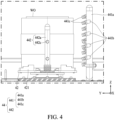
- FIG. 4 is an enlarged view of the washing tank 30 according to the cross-sectional view of the high-pressure washer 1 illustrated in FIG. 3 .
- FIG. 5 is a schematic perspective view of the washing tank 30 of the high-pressure washer 1, according to an embodiment.
- the washing assembly 40 disposed in the washing tank 30 may include the rotating module 42 and the washing module 44.
- the washing assembly 40 may wash the WO.
- the WO may be a drum-shaped unit including a bottom and a side wall extending from the bottom to one side and forming a cavity.
- the rotating module 42 may be disposed on the bottom surface of the washing tank 30 and may rotate around the axis perpendicular to the bottom surface.
- the WO is coupled to the rotating module 42 and may rotate together with the rotating module 42.
- the jig 421 may be disposed on the upper portion of the rotating module 42.
- the jig 421 may securely fix the WO to the rotating module 42 such that even when washing water with high spraying pressure is sprayed onto the WO from the washing module 44 the WO may rotate along with the rotating module 42.
- the jig 421 may fix the WO using an interference fit method, a coupling method, a magnetic coupling method, an electromagnetic coupling method, and the like, and commonly used fixing methods may be used.
- Two or more jigs 421 may be disposed on one rotating module 42.
- the spacing between the jigs 421 may be constantly formed.
- an angle formed between two adjacent jigs 421 may be constant surrounding the second washing element 442.
- the washing module 44 may include the first washing element 441 and the second washing element 442.
- the first washing element 441 may be disposed to be spaced apart from the rotating module 42 and may wash the outer surface of the WO.
- the second washing element 442 may be disposed to correspond to the rotation shaft of the rotating module 42. That is, the second washing element 442 may extend upward from the center of the rotating module 42.
- the inner surface of the WO may be washed.
- the first washing element 441 and the second washing element 442 may each include a spray stem 441a, 442a, a spray branch 441b, 442b, and a spray nozzle 441c, 442c.
- the spray stem 441a, 442a may be formed to extend upward from the bottom surface of the washing tank.
- the spray stem 441a, 442a may move washing water required for washing and transfer the washing water to the spray branch 441b, 442b.
- the spray branch 441b, 442b may be formed to extend outward from the spray stem 441a, 442a.
- the spray branch 441b, 442b may be formed to extend in the direction traversing the longitudinal direction of the spray stem 441a, 442a.
- the spray branch 441b, 442b may be formed to be perpendicular to the longitudinal direction of the spray stem 441a, 442a.
- the spray branch 441b, 442b may not necessarily have to be formed in a straight line and may include a curved shape.
- a plurality of spray branches 441b and 442b may extend from one spray stem 441a, 442a.
- the plurality of spray branches 441b and 442b may be formed with the same or different lengths/shapes.
- the spray nozzle 441c, 442c may be disposed at an end of the spray branch 441b, 442b.
- the spray nozzle 441c, 442c may include a nozzle having a diameter much less than the inner diameter of the spray branch 441b, 442b, thereby enabling high-pressure spraying of washing water. As illustrated in FIG. 4 , all spray nozzles 441c according to an embodiment may be disposed to face the WO. However, the plurality of spray nozzles 441c may not all spray washing water in parallel directions. The plurality of spray nozzles 441c may wash the outer surface of a wider range of the WO by having different spray angles, thus achieving improved washing efficiency.
- each spray nozzle 441c, 442c may spray washing water in the direction in which the spray nozzle 441c, 442c is arranged, and as the WO coupled to the rotating module 42 by the jig 421 rotates, washing of all surfaces of the WO may be achieved.
- a first washing assembly 40A and a second washing assembly 40B may each include a rotating module 42 and a washing module 44 including the first washing element 441 and the second washing element 442.
- the rotating module 42 included in the first washing assembly 40A and a rotating module (not shown) included in the second washing assembly 40B may be driven by a single motor (e.g., the motor 72 of FIG. 3 ) by a power transmission unit (e.g., the power transmission unit 74 of FIG. 4 ).
- the first washing element 441 included in the first washing assembly 40A and the second washing element (not shown) included in the second washing assembly 40B may be formed to branch out from a single spray root 440.
- the high-pressure washer 1 may start operating when the cover 20 is closed after the WO is attached to the jig 421 of the rotating module 42.
- the pump 60 may pull the washing water stored in the water storage tank 50 and transport the washing water to the washing assembly 40.
- the washing water transported to the washing assembly 40 may be sprayed onto the WO by the first washing element 441 and the second washing element 442 of the washing module 44. While the washing water is sprayed onto the WO, the WO may be easily washed on all sides by rotating around a single axis by the rotating module 42.
- the washing water used to wash the WO may fall downward due to gravity and may be returned to the water storage tank 50.
- the washing water returned to the water storage tank 50 may contain glue residue and other contaminants, and these contaminants may be self-cleaned by being discharged to the outside of the high-pressure washer 1 by the water cleaning module 90.
- the washing water in the water storage tank 50 may be moved to the filter device 70 by the pump 60, filtered, and then transferred to the washing assembly 40.
- the high-pressure washer 1 using reusable washing water may operate.
- the series of operations of the high-pressure washer 1 may be controlled by a user through a touch panel included in the screen 12 according to FIG. 1 .
Landscapes
- Cleaning By Liquid Or Steam (AREA)
Abstract
Description
- The following embodiments relate to a high-pressure washer.
- In general, cigarette machines, packaging machines, and low ignition propensity (LIP) coating units, which frequently use adhesives in industrial settings, utilize the adhesive supply nozzles of the adhesive application device to supply glue-type adhesives, thereby adhesively packaging objects to be packaged. Drums used for storing adhesives in adhesive application devices are prone to contamination due to various substances scattering during the production process, so the drums need to be cleaned at regular intervals. In particular, because adhesives have strong adhesive properties and solidifies over time, simply impregnating a drum in cleaning water is not enough to keep the drum clean. Therefore, cleaning requires using powerful cleaning water.
- Conventionally, the adhesive stuck to a drum is softened by continuously supplying hot water, and then the packaging machine is cleaned manually by workers. This method results in high consumption of cleaning water, requires a lot of cleaning time, and leads to significant energy waste due to the use of gas for heating the water.
- An embodiment provides a high-pressure washer that reduces contamination and other issues caused by solidified adhesives by cleaning parts to which adhesive materials are applied at regular intervals.
- An embodiment provides a high-pressure washer that filters cleaning water sucked from a water tank in a filtration device and then circulates it as cleaning water, thereby reducing the waste of the cleaning water by allowing the water in the water tank to be used repeatedly.
- A high-pressure washer according to various embodiments includes a main body, a cover configured to cover an upper portion of the main body, a washing tank formed between the main body and the cover, a washing assembly disposed in the washing tank, wherein the washing assembly includes a washing module configured to clean a washing object, and wherein the washing module includes a first washing element disposed outside the washing object and configured to spray washing water and a second washing element disposed in the washing object and configured to spray washing water.
- In an embodiment, the washing assembly may further include a rotating module configured to rotate the washing object.
- In an embodiment, the high-pressure washer may further include a jig configured to fix the washing object to the rotating module.
- In an embodiment, the first washing element and the second washing element may include a spray stem extending upward in the washing tank and through which washing water moves, a spray branch extending outward from the spray stem, and a spray nozzle disposed at an end of the spray branch.
- In an embodiment, the spray branch may extend in a direction traversing a longitudinal direction of the spray stem, and the spray nozzle may face the washing object.
- In an embodiment, the high-pressure washer may further include a water storage tank formed on a bottom of the washing tank, wherein washing water that washes the washing object may be returned to the water storage tank, filtered, and reused.
- In an embodiment, the washing assembly may further include a rotating module configured to rotate the washing object, the rotating module may be rotated by a motor disposed to be spaced apart from the washing tank and the water storage tank, and the motor may be connected to the rotating module by a power transmission unit.
- In an embodiment, the high-pressure washer may further include a water cleaning module disposed in the water storage tank, wherein the water cleaning module may include a suction port formed at a height corresponding to a water surface level of the washing water stored in the water storage tank and a discharge port configured to discharge floating matter introduced into the suction port to outside.
- In an embodiment, the high-pressure washer may further include a circulation port in fluid communication with the water storage tank, wherein the circulation port may be configured to transport the washing water returned to the water storage tank to a filter device.
- In an embodiment, the high-pressure washer may further include a heater disposed in the water storage tank and configured to heat the washing water.
- In an embodiment, two or more of the washing assemblies may be disposed in the washing tank.
- In an embodiment, the second washing element may be disposed on a central upper portion of the rotating module.
- A high-pressure washer according to various embodiments includes a main body, a cover configured to cover the main body, a washing tank formed between the main body and the cover, and a washing assembly disposed in the washing tank, wherein the washing assembly may include a rotating module configured to rotate a washing object, and a washing module configured to clean the washing object, and wherein the washing module may include a first washing element disposed to be spaced apart from the rotating module and a second washing element disposed at a center of the rotating module.
- In an embodiment, the first washing element may include a first nozzle facing an outer portion of the washing object, and the second washing element may include a second nozzle disposed to face an inner portion of the washing object.
- A high-pressure washer according to an embodiment may reduce contamination and other issues caused by solidified adhesives by cleaning parts to which adhesive materials are applied at regular intervals.
- The high-pressure washer according to an embodiment may filter cleaning water sucked from a water tank in a filtration device and then circulate it as cleaning water, thereby reducing the waste of the cleaning water by allowing the water in the water tank to be used repeatedly.
- The effects of the high-pressure washer according to an embodiment are not limited to the above-mentioned effects, and other unmentioned effects can be clearly understood from the above description by those having ordinary skill in the technical field to which the present disclosure pertains.
-
-
FIG. 1 is a schematic perspective view of a high-pressure washer according to an embodiment. -
FIG. 2 is a schematic rear view of a high-pressure washer according to an embodiment. -
FIG. 3 is a schematic cross-sectional view of a high-pressure washer according to an embodiment. -
FIG. 4 is an enlarged view of a region X of the high-pressure washer illustrated inFIG. 3 , according to an embodiment. -
FIG. 5 is a schematic perspective view of a washing tank of a high-pressure washer, according to an embodiment. - The terms used to describe the embodiments are selected from among common terms that are currently widely used, in consideration of their function in the disclosure. However, different terms may be used depending on an intention of one of ordinary skill in the art, a precedent, or the advent of new technology. Also, in particular cases, the terms are discretionally selected by the applicant of the disclosure, and the meaning of those terms will be described in detail in the corresponding part of the detailed description. Therefore, the terms used in the disclosure are not merely designations of the terms, but the terms are defined based on the meaning of the terms and content throughout the disclosure.
- It will be understood that when a certain part "includes" a certain component, the part does not exclude another component but may further include another component, unless the context clearly dictates otherwise. Also, terms such as "unit," "module," etc., as used in the specification may refer to a part for processing at least one function or operation and which may be implemented as hardware, software, or a combination of hardware and software.
- As used herein, an expression such as "at least one of' that precedes listed components modifies not each of the listed components but all the listed components. For example, the expression "at least one of a, b, and c" should be construed as including a, b, c, a and b, a and c, b and c, or a, b, and c.
- In the following embodiments, the term "aerosol generating article" may refer to an article that accommodates a medium, in which an aerosol passes through the article and the medium is transferred. A representative example of the aerosol generating article may be a cigarette. However, the scope of the disclosure is not limited thereto.
- In the following embodiments, "upward" or "upper" refers to a direction (e.g., +Z direction in the drawing) away from the bottom surface or a portion located in that direction, and "downward" or "lower" refers to a direction (e.g., -Z direction in the drawing) toward the bottom surface or a portion located in that direction. The terms "upper" and "lower" may be used to describe relative positions of components of a high-pressure washer.
- An embodiment may be implemented in the form of a recording medium including instructions executable by a computer, such as a program module executable by the computer. A computer-readable medium may be any available medium that can be accessed by a computer and includes all of a volatile medium, a non-volatile medium, a removable medium, and a non-removable medium. In addition, the computer-readable medium may include both a computer storage medium and a communication medium. The computer storage medium includes all of a volatile medium, a non-volatile medium, a removable medium, and a non-removable medium implemented by any method or technology for storage of information such as computer-readable instructions, data structures, program modules or other data. The communication medium typically includes computer-readable instructions, data structures, other data in modulated data signals such as program modules, or other transmission mechanisms, and includes any information transfer medium.
-
FIG. 1 is a schematic perspective view of a high-pressure washer 1, according to an embodiment.FIG. 2 is a schematic rear view of the high-pressure washer 1 according to an embodiment. - Referring to
FIGS. 1 and2 , the high-pressure washer 1 may include amain body 10, acover 20, awashing tank 30, awashing assembly 40, apump 60, and afilter device 70. - In an embodiment, the
main body 10 may be formed of a sturdy material to protect some components included in the high-pressure washer 1. Themain body 10 according to an embodiment may be formed in a hexahedral shape. Themain body 10 may include a water storage tank (e.g., awater storage tank 50 ofFIG. 3 ). Themain body 10 according to an embodiment may include awheel 11 on the bottom. Thewheel 11 may facilitate the movement of the heavy high-pressure washer 1. Themain body 10 according to an embodiment may include ascreen 12. Thescreen 12 may display the operational status and monitoring control alarms of the high-pressure washer 1, such as washing water pressure, washing water temperature, filter pressure, washing time, water level control, and the number of washing water replacements. Thescreen 12 may include a touch panel, so a user may control the operational status through the touch panel. - In an embodiment, the
cover 20 may be disposed to cover the upper portion of themain body 10. Thecover 20 may be hinged to the upper portion of themain body 10 and may be open and closed. A side surface of thecover 20 may be connected to themain body 10 by a hydraulic orpneumatic cylinder 21. In an embodiment, thecover 20 may further include awindow 22. Thewindow 22 may be formed of a transparent material such as glass or acrylic. The user may easily check the washing situation of the interior of thewashing tank 30 through thewindow 22. In an embodiment, thecover 20 may further include ahandle 23. The user may easily open and close thecover 20 by holding thehandle 23. - In an embodiment, the
washing tank 30 may include a space formed between themain body 10 and thecover 20. Thewashing tank 30 is a space in which actual washing of a washing object (WO) occurs. In an embodiment, the WO may be a drum-shaped unit including a bottom and a side wall extending from the bottom to one side and forming a cavity. Awashing assembly 40 may be disposed in thewashing tank 30. Two ormore washing assemblies 40 may be disposed in thewashing tank 30. Thewashing tank 30 may further include a drainage hole (not shown) in the bottom surface of thewashing tank 30. Washing water sprayed onto the WO by thewashing assembly 40 may be returned to a water storage tank (e.g., thewater storage tank 50 ofFIG. 3 ) in the main body through the drainage hole. - In an embodiment, the
washing assembly 40 may include arotating module 42 and awashing module 44. The rotatingmodule 42 may be disposed on the bottom of thewashing tank 30 and may rotate about an axis perpendicular to the bottom. The WO is coupled to therotating module 42 and may rotate together with the rotatingmodule 42. Thewashing module 44 may be formed to extend upward from the bottom surface of thewashing tank 30. Washing water is sprayed from a nozzle included in thewashing module 44 toward the WO to clean the WO. Thewashing module 44 may include afirst washing element 441 and asecond washing element 442. Thefirst washing element 441 may be disposed to be spaced apart from the WO and may wash the outer surface of the WO. Thesecond washing element 442 may be disposed in the WO and may wash the inner surface of the WO. Thewashing assembly 40 is described in detail below with reference toFIGS. 4 and5 . - In an embodiment, the
pump 60 may suck washing water from the water storage tank (e.g., thewater storage tank 50 ofFIG. 3 ) through acirculation port 62 and transport the washing water to thefilter device 70. Thecirculation port 62 may be in fluid communication with thewater storage tank 50. Thepump 60 may supply the washing water purified by thefilter device 70 back to thewashing assembly 40. - In an embodiment, the
filter device 70 may filter washing water used to wash a WO (e.g., the WO ofFIG. 1 ) in a washing tank (e.g., thewashing tank 30 ofFIG. 1 ). The washing water filtered by thefilter device 70 may be sprayed back into thewashing tank 30 through thewashing assembly 40. Thefilter device 70 may include at least one filtering element, such as a filter screen, a sedimentation filter, an activated carbon filter, an osmotic pressure filter, and a high efficiency particulate air (HEPA) filter. The filtering element included in thefilter device 70 according to an embodiment may be replaced after being used approximately 1,000 times. - In an embodiment, the washing water may be repeatedly reused while being circulated through the
water storage tank 50 and thefilter device 70 by thepump 60. In this case, the number of repeated uses of the washing water may be determined depending on the type and shape of a glue part. For example, when a drum-shaped WO 100 is washed, the washing water may be reused approximately 100 times. -
FIG. 3 is a schematic cross-sectional view of the high-pressure washer 1 ofFIG. 1 taken along line 3-3', according to an embodiment. Referring toFIG. 3 , the high-pressure washer 1 according to an embodiment may further include thewater storage tank 50, aheater 80, and awater cleaning module 90. - In an embodiment, the
water storage tank 50 may be formed on the bottom of thewashing tank 30. Thewater storage tank 50 may store the washing water supplied to thewashing module 44. Theheater 80 may be disposed in the inner space of thewater storage tank 50. Theheater 80 may be an electrically operated heater. Theheater 80 may heat washing water. Theheater 80 may further include a temperature sensor (not shown), and the temperature sensor may detect the temperature of the washing water inside thewater storage tank 50 to ensure a constant temperature is maintained. In an embodiment, thewater storage tank 50 may be partitioned from other components (e.g., thepump 60, thefilter device 70, and a motor 72) of the high-pressure washer 1. Since thewater storage tank 50 is a space for storing washing water, it is desirable that electronic components sensitive to water or foreign substances are placed away from thewater storage tank 50. In an embodiment, the washing water sprayed by thewashing module 44 may wash the WO, and the contaminated washing water resulting from washing the WO may be returned to thewater storage tank 50. The contaminated washing water in thewater storage tank 50 may be moved to thefilter device 70 and filtered. - In an embodiment, the
motor 72 may generate driving force necessary to rotate therotating module 42. Themotor 72 may be spaced apart from thewashing tank 30 and thewater storage tank 50. Since the washing water and foreign substances washed by high-pressure washing water are dispersed in all directions, themotor 72 may be disposed to be spaced apart from thewashing tank 30 and thewater storage tank 50 to prevent themotor 72 from breaking down. In order to easily transfer the power of themotor 72 to therotating module 42, the high-pressure washer 1 may further include apower transmission unit 74. Thepower transmission unit 74 is an element for transmitting the rotational force of themotor 72 to therotating module 42 and may include a chain, a conveyor belt, a timing belt, a worm gear, a gear box, and the like. When the high-pressure washer 1 according to an embodiment includes two or more rotating modules 42 (e.g., the high-pressure washer ofFIG. 5 includes two rotating modules 42), thepower transmission unit 74 may be disposed to connect themotor 72 to all passive power transmission parts (not shown) formed at the bottom of the two or morerotating modules 42. - Continuously referring to
FIG. 3 , thewater cleaning module 90 may be disposed in thewater storage tank 50. Thewater cleaning module 90 may include asuction port 92 and adischarge port 94. The height of thesuction port 92 may be disposed to correspond to the water surface level of the washing water stored in thewater storage tank 50. As the washing water used to wash the WO falls from thewashing tank 30 to thewater storage tank 50 by gravity, waves may be formed on the surface of the washing water stored in thewater storage tank 50. Due to the waves of the washing water, floating matters may overflow into thesuction port 92 of thewater cleaning module 90. The floating matters (e.g., glue product residue, foreign substances, etc.) introduced into thesuction port 92 may move along thedischarge port 94 connected to thesuction port 92 and may be discharged to the outside of a high-pressure washer (e.g., the high-pressure washer 1 ofFIG. 1 ). In an embodiment, thewater cleaning module 90 may operate automatically at predetermined time intervals. In an embodiment, thewater cleaning module 90 may operate only when the WO is not coupled to ajig 421 of therotating module 42. The cycle, duration, and the like of the automatic operation of thewater cleaning module 90 may be viewed and controlled through a screen (e.g., thescreen 12 ofFIG. 1 ) of the high-pressure washer (e.g., the high-pressure washer 1 ofFIG. 1 ). -
FIG. 4 is an enlarged view of thewashing tank 30 according to the cross-sectional view of the high-pressure washer 1 illustrated inFIG. 3 .FIG. 5 is a schematic perspective view of thewashing tank 30 of the high-pressure washer 1, according to an embodiment. - Referring to
FIGS. 4 and5 , thewashing assembly 40 disposed in thewashing tank 30 may include the rotatingmodule 42 and thewashing module 44. Thewashing assembly 40 may wash the WO. In an embodiment, the WO may be a drum-shaped unit including a bottom and a side wall extending from the bottom to one side and forming a cavity. - In an embodiment, the rotating
module 42 may be disposed on the bottom surface of thewashing tank 30 and may rotate around the axis perpendicular to the bottom surface. The WO is coupled to therotating module 42 and may rotate together with the rotatingmodule 42. Thejig 421 may be disposed on the upper portion of therotating module 42. Thejig 421 may securely fix the WO to therotating module 42 such that even when washing water with high spraying pressure is sprayed onto the WO from thewashing module 44 the WO may rotate along with the rotatingmodule 42. Thejig 421 may fix the WO using an interference fit method, a coupling method, a magnetic coupling method, an electromagnetic coupling method, and the like, and commonly used fixing methods may be used. Two ormore jigs 421 may be disposed on one rotatingmodule 42. When two ormore jigs 421 are included in one rotatingmodule 42, the spacing between thejigs 421 may be constantly formed. For example, an angle formed between twoadjacent jigs 421 may be constant surrounding thesecond washing element 442. - In an embodiment, the
washing module 44 may include thefirst washing element 441 and thesecond washing element 442. Thefirst washing element 441 may be disposed to be spaced apart from the rotatingmodule 42 and may wash the outer surface of the WO. Thesecond washing element 442 may be disposed to correspond to the rotation shaft of therotating module 42. That is, thesecond washing element 442 may extend upward from the center of therotating module 42. The inner surface of the WO may be washed. - In an embodiment, the
first washing element 441 and thesecond washing element 442 may each include aspray stem spray branch spray nozzle spray stem spray stem spray branch spray branch spray stem spray branch spray stem spray branch spray stem spray branch spray branches spray stem spray branches spray nozzle spray branch spray nozzle spray branch FIG. 4 , all spraynozzles 441c according to an embodiment may be disposed to face the WO. However, the plurality ofspray nozzles 441c may not all spray washing water in parallel directions. The plurality ofspray nozzles 441c may wash the outer surface of a wider range of the WO by having different spray angles, thus achieving improved washing efficiency. - In an embodiment, each
spray nozzle spray nozzle rotating module 42 by thejig 421 rotates, washing of all surfaces of the WO may be achieved. - Continuously referring to
FIG. 5 , two ormore washing assemblies 40 may be disposed in thewashing tank 30. Afirst washing assembly 40A and asecond washing assembly 40B may each include arotating module 42 and awashing module 44 including thefirst washing element 441 and thesecond washing element 442. The rotatingmodule 42 included in thefirst washing assembly 40A and a rotating module (not shown) included in thesecond washing assembly 40B may be driven by a single motor (e.g., themotor 72 ofFIG. 3 ) by a power transmission unit (e.g., thepower transmission unit 74 ofFIG. 4 ). Thefirst washing element 441 included in thefirst washing assembly 40A and the second washing element (not shown) included in thesecond washing assembly 40B may be formed to branch out from asingle spray root 440. - Hereinafter, a method of operating the high-
pressure washer 1 according to an embodiment is described as an example with reference toFIGS. 1 to 5 . The high-pressure washer 1 may start operating when thecover 20 is closed after the WO is attached to thejig 421 of therotating module 42. Thepump 60 according to an embodiment may pull the washing water stored in thewater storage tank 50 and transport the washing water to thewashing assembly 40. The washing water transported to thewashing assembly 40 may be sprayed onto the WO by thefirst washing element 441 and thesecond washing element 442 of thewashing module 44. While the washing water is sprayed onto the WO, the WO may be easily washed on all sides by rotating around a single axis by the rotatingmodule 42. The washing water used to wash the WO may fall downward due to gravity and may be returned to thewater storage tank 50. The washing water returned to thewater storage tank 50 may contain glue residue and other contaminants, and these contaminants may be self-cleaned by being discharged to the outside of the high-pressure washer 1 by thewater cleaning module 90. The washing water in thewater storage tank 50 may be moved to thefilter device 70 by thepump 60, filtered, and then transferred to thewashing assembly 40. Through the above series of processes, the high-pressure washer 1 using reusable washing water may operate. The series of operations of the high-pressure washer 1 may be controlled by a user through a touch panel included in thescreen 12 according toFIG. 1 . - Although the embodiments have been described with reference to the limited drawings, one of ordinary skill in the art may apply various technical modifications and variations based thereon. For example, suitable results may be achieved if the described techniques are performed in a different order, and/or if components in a described system, architecture, device, or circuit are combined in a different manner, and/or replaced or supplemented by other components or their equivalents.
- Therefore, other implementations, other embodiments, and equivalents of the claims are within the scope of the following claims.
Claims (14)
- A high-pressure washer comprising:a main body;a cover configured to cover an upper portion of the main body;a washing tank formed between the main body and the cover;a washing assembly disposed in the washing tank,wherein the washing assembly comprises a washing module configured to clean a washing object, andwherein the washing module comprises a first washing element disposed outside the washing object and configured to spray washing water and a second washing element disposed in the washing object and configured to spray washing water.
- The high-pressure washer of claim 1, wherein the washing assembly further comprises a rotating module configured to rotate the washing object.
- The high-pressure washer of claim 2, further comprising a jig configured to fix the washing object to the rotating module.
- The high-pressure washer of claim 1, wherein the first washing element and the second washing element comprise:a spray stem extending upward in the washing tank and through which washing water moves;a spray branch extending outward from the spray stem; anda spray nozzle disposed at an end of the spray branch.
- The high-pressure washer of claim 4, wherein the spray branch extends in a direction traversing a longitudinal direction of the spray stem, and the spray nozzle faces the washing obj ect.
- The high-pressure washer of claim 1, further comprising:a water storage tank formed on a bottom of the washing tank,wherein washing water that washes the washing object is returned to the water storage tank, filtered, and reused.
- The high-pressure washer of claim 6, whereinthe washing assembly further comprises a rotating module configured to rotate the washing object, andthe rotating module is rotated by a motor disposed to be spaced apart from the washing tank and the water storage tank, and the motor is connected to the rotating module by a power transmission unit.
- The high-pressure washer of claim 6, further comprising:a water cleaning module disposed in the water storage tank,wherein the water cleaning module comprises a suction port formed at a height corresponding to a water surface level of the washing water stored in the water storage tank and a discharge port configured to discharge floating matter introduced into the suction port to outside.
- The high-pressure washer of claim 8, further comprising:a circulation port in fluid communication with the water storage tank,wherein the circulation port is configured to transport the washing water returned to the water storage tank to a filter device.
- The high-pressure washer of claim 6, further comprising:
a heater disposed in the water storage tank and configured to heat the washing water. - The high-pressure washer of claim 1, wherein two or more of the washing assemblies are disposed in the washing tank.
- The high-pressure washer of claim 2, wherein the second washing element is disposed on a central upper portion of the rotating module.
- A high-pressure washer comprising:a main body;a cover configured to cover the main body;a washing tank formed between the main body and the cover; anda washing assembly disposed in the washing tank,wherein the washing assembly comprises:a rotating module configured to rotate a washing object; anda washing module configured to clean the washing object, andwherein the washing module comprises a first washing element disposed to be spaced apart from the rotating module and a second washing element disposed at a center of the rotating module.
- The high-pressure washer of claim 13, wherein the first washing element comprises a first nozzle facing an outer portion of the washing object, and the second washing element comprises a second nozzle disposed to face an inner portion of the washing object.
Applications Claiming Priority (2)
| Application Number | Priority Date | Filing Date | Title |
|---|---|---|---|
| KR1020230038682A KR102929713B1 (en) | 2023-03-24 | 2023-03-24 | High pressure washer |
| PCT/KR2023/004251 WO2024204888A1 (en) | 2023-03-24 | 2023-03-30 | High-pressure washing device |
Publications (2)
| Publication Number | Publication Date |
|---|---|
| EP4464431A1 true EP4464431A1 (en) | 2024-11-20 |
| EP4464431A4 EP4464431A4 (en) | 2025-09-03 |
Family
ID=92459091
Family Applications (1)
| Application Number | Title | Priority Date | Filing Date |
|---|---|---|---|
| EP23920287.2A Pending EP4464431A4 (en) | 2023-03-24 | 2023-03-30 | HIGH-PRESSURE WASHING DEVICE |
Country Status (4)
| Country | Link |
|---|---|
| EP (1) | EP4464431A4 (en) |
| KR (1) | KR102929713B1 (en) |
| CN (1) | CN121646513A (en) |
| WO (1) | WO2024204888A1 (en) |
Families Citing this family (1)
| Publication number | Priority date | Publication date | Assignee | Title |
|---|---|---|---|---|
| CN120243580B (en) * | 2025-05-30 | 2025-08-22 | 杭州腾励传动科技股份有限公司 | A device for detecting internal and external damage of the cylindrical shell of a high-speed transmission shaft |
Family Cites Families (9)
| Publication number | Priority date | Publication date | Assignee | Title |
|---|---|---|---|---|
| US7520288B2 (en) * | 2004-08-18 | 2009-04-21 | Rhodes Laurence M | Cleaning machine |
| KR101139035B1 (en) | 2009-09-15 | 2012-05-08 | 박정곤 | Apparatus for ionized cleaning bottles |
| JP5046417B1 (en) * | 2011-11-21 | 2012-10-10 | 小嶺機械株式会社 | Water washing method and water washing apparatus for dehydrated basket for food washing |
| KR20150093375A (en) * | 2014-02-07 | 2015-08-18 | 김연일 | washimg apparatus for machinery part |
| WO2017090505A1 (en) * | 2015-11-24 | 2017-06-01 | 東京エレクトロン株式会社 | Substrate liquid treatment device, substrate liquid treatment method, and memory medium |
| CN111408589A (en) * | 2020-03-24 | 2020-07-14 | 湖南鑫源缸套有限责任公司 | Full self-cleaning system of cylinder jacket |
| KR102505998B1 (en) | 2020-09-24 | 2023-03-06 | 이종선 | Apparatus for washing drink container |
| KR102252781B1 (en) * | 2020-12-18 | 2021-05-17 | 비오티 주식회사 | Golf club washing apparatus |
| CN113522860B (en) * | 2021-09-14 | 2021-12-07 | 盛吉盛(宁波)半导体科技有限公司 | Semiconductor quartz component cleaning equipment |
-
2023
- 2023-03-24 KR KR1020230038682A patent/KR102929713B1/en active Active
- 2023-03-30 EP EP23920287.2A patent/EP4464431A4/en active Pending
- 2023-03-30 WO PCT/KR2023/004251 patent/WO2024204888A1/en not_active Ceased
- 2023-03-30 CN CN202380019645.7A patent/CN121646513A/en active Pending
Also Published As
| Publication number | Publication date |
|---|---|
| EP4464431A4 (en) | 2025-09-03 |
| KR20240143411A (en) | 2024-10-02 |
| CN121646513A (en) | 2026-03-10 |
| WO2024204888A1 (en) | 2024-10-03 |
| KR102929713B1 (en) | 2026-02-24 |
Similar Documents
| Publication | Publication Date | Title |
|---|---|---|
| EP4442376A1 (en) | High-pressure washer | |
| JP3131149B2 (en) | Flow liquid scrubber cleaning method and apparatus | |
| EP4467251A1 (en) | High-pressure cleaning device | |
| US8958064B2 (en) | Inspection device with rotatable lighting element housing | |
| CA2940006C (en) | Inkjet-head cleaning device and method | |
| FI90355B (en) | Process and apparatus for cleaning objects with solvents which are hazardous to the environment, especially halogenated hydrocarbons | |
| KR102929713B1 (en) | High pressure washer | |
| KR102949986B1 (en) | High pressure washer | |
| KR100764573B1 (en) | Drum Washer | |
| CN118613336A (en) | High pressure cleaner | |
| RU2845851C2 (en) | High pressure washer | |
| KR101113272B1 (en) | Filter cleaner | |
| CN212370686U (en) | Cleaning equipment | |
| RU2846194C2 (en) | High pressure cleaning device | |
| KR20230165420A (en) | Do drum washing chapter | |
| CN212883826U (en) | cleaning device | |
| CN118613337A (en) | High pressure cleaner | |
| JP4482304B2 (en) | Cleaning device for battery metal cans | |
| CN117139307B (en) | Paint waste liquid treater | |
| JP2005087804A (en) | Method of washing vessel and tubular body | |
| KR20170115673A (en) | a apparatus polishing surface of machine part processing and method using the apparatus | |
| CN215354944U (en) | Cleaning equipment for automobile parts | |
| KR102965575B1 (en) | PCB cleaning device using robot | |
| KR100856081B1 (en) | Cleaning equipment | |
| KR100719867B1 (en) | Wood coating device using masking band |
Legal Events
| Date | Code | Title | Description |
|---|---|---|---|
| STAA | Information on the status of an ep patent application or granted ep patent |
Free format text: STATUS: UNKNOWN |
|
| STAA | Information on the status of an ep patent application or granted ep patent |
Free format text: STATUS: THE INTERNATIONAL PUBLICATION HAS BEEN MADE |
|
| PUAI | Public reference made under article 153(3) epc to a published international application that has entered the european phase |
Free format text: ORIGINAL CODE: 0009012 |
|
| STAA | Information on the status of an ep patent application or granted ep patent |
Free format text: STATUS: REQUEST FOR EXAMINATION WAS MADE |
|
| 17P | Request for examination filed |
Effective date: 20240814 |
|
| AK | Designated contracting states |
Kind code of ref document: A1 Designated state(s): AL AT BE BG CH CY CZ DE DK EE ES FI FR GB GR HR HU IE IS IT LI LT LU LV MC ME MK MT NL NO PL PT RO RS SE SI SK SM TR |
|
| RIC1 | Information provided on ipc code assigned before grant |
Ipc: B05B 3/02 20060101ALN20250508BHEP Ipc: B05B 1/14 20060101ALN20250508BHEP Ipc: B05B 14/40 20180101ALI20250508BHEP Ipc: B05B 9/04 20060101ALI20250508BHEP Ipc: B08B 3/02 20060101ALI20250508BHEP Ipc: B08B 3/10 20060101ALI20250508BHEP Ipc: B08B 3/14 20060101ALI20250508BHEP Ipc: B08B 9/28 20060101AFI20250508BHEP |
|
| A4 | Supplementary search report drawn up and despatched |
Effective date: 20250804 |
|
| RIC1 | Information provided on ipc code assigned before grant |
Ipc: B08B 9/28 20060101AFI20250729BHEP Ipc: B08B 3/14 20060101ALI20250729BHEP Ipc: B08B 3/10 20060101ALI20250729BHEP Ipc: B08B 3/02 20060101ALI20250729BHEP Ipc: B05B 9/04 20060101ALI20250729BHEP Ipc: B05B 14/40 20180101ALI20250729BHEP Ipc: B05B 1/14 20060101ALN20250729BHEP Ipc: B05B 3/02 20060101ALN20250729BHEP |