EP4464222A1 - Cleaning brush and smart cleaning apparatus - Google Patents
Cleaning brush and smart cleaning apparatus Download PDFInfo
- Publication number
- EP4464222A1 EP4464222A1 EP22918191.2A EP22918191A EP4464222A1 EP 4464222 A1 EP4464222 A1 EP 4464222A1 EP 22918191 A EP22918191 A EP 22918191A EP 4464222 A1 EP4464222 A1 EP 4464222A1
- Authority
- EP
- European Patent Office
- Prior art keywords
- end portion
- limiting
- guide sleeve
- cleaning brush
- brush according
- Prior art date
- Legal status (The legal status is an assumption and is not a legal conclusion. Google has not performed a legal analysis and makes no representation as to the accuracy of the status listed.)
- Pending
Links
Images


Classifications
-
- B—PERFORMING OPERATIONS; TRANSPORTING
- B08—CLEANING
- B08B—CLEANING IN GENERAL; PREVENTION OF FOULING IN GENERAL
- B08B1/00—Cleaning by methods involving the use of tools
- B08B1/10—Cleaning by methods involving the use of tools characterised by the type of cleaning tool
- B08B1/12—Brushes
-
- A—HUMAN NECESSITIES
- A46—BRUSHWARE
- A46B—BRUSHES
- A46B13/00—Brushes with driven brush bodies or carriers
- A46B13/001—Cylindrical or annular brush bodies
-
- A—HUMAN NECESSITIES
- A46—BRUSHWARE
- A46B—BRUSHES
- A46B13/00—Brushes with driven brush bodies or carriers
- A46B13/001—Cylindrical or annular brush bodies
- A46B13/005—Cylindrical or annular brush bodies made up of a series of longitudinal strips or segments
-
- A—HUMAN NECESSITIES
- A46—BRUSHWARE
- A46B—BRUSHES
- A46B13/00—Brushes with driven brush bodies or carriers
- A46B13/02—Brushes with driven brush bodies or carriers power-driven carriers
-
- A—HUMAN NECESSITIES
- A46—BRUSHWARE
- A46D—MANUFACTURE OF BRUSHES
- A46D3/00—Preparing, i.e. Manufacturing brush bodies
-
- A—HUMAN NECESSITIES
- A47—FURNITURE; DOMESTIC ARTICLES OR APPLIANCES; COFFEE MILLS; SPICE MILLS; SUCTION CLEANERS IN GENERAL
- A47L—DOMESTIC WASHING OR CLEANING; SUCTION CLEANERS IN GENERAL
- A47L11/00—Machines for cleaning floors, carpets, furniture, walls, or wall coverings
- A47L11/24—Floor-sweeping machines, motor-driven
-
- A—HUMAN NECESSITIES
- A47—FURNITURE; DOMESTIC ARTICLES OR APPLIANCES; COFFEE MILLS; SPICE MILLS; SUCTION CLEANERS IN GENERAL
- A47L—DOMESTIC WASHING OR CLEANING; SUCTION CLEANERS IN GENERAL
- A47L11/00—Machines for cleaning floors, carpets, furniture, walls, or wall coverings
- A47L11/40—Parts or details of machines not provided for in groups A47L11/02 - A47L11/38, or not restricted to one of these groups, e.g. handles, arrangements of switches, skirts, buffers, levers
- A47L11/4036—Parts or details of the surface treating tools
- A47L11/4041—Roll shaped surface treating tools
-
- A—HUMAN NECESSITIES
- A47—FURNITURE; DOMESTIC ARTICLES OR APPLIANCES; COFFEE MILLS; SPICE MILLS; SUCTION CLEANERS IN GENERAL
- A47L—DOMESTIC WASHING OR CLEANING; SUCTION CLEANERS IN GENERAL
- A47L9/00—Details or accessories of suction cleaners, e.g. mechanical means for controlling the suction or for effecting pulsating action; Storing devices specially adapted to suction cleaners or parts thereof; Carrying-vehicles specially adapted for suction cleaners
- A47L9/02—Nozzles
- A47L9/04—Nozzles with driven brushes or agitators
-
- A—HUMAN NECESSITIES
- A47—FURNITURE; DOMESTIC ARTICLES OR APPLIANCES; COFFEE MILLS; SPICE MILLS; SUCTION CLEANERS IN GENERAL
- A47L—DOMESTIC WASHING OR CLEANING; SUCTION CLEANERS IN GENERAL
- A47L9/00—Details or accessories of suction cleaners, e.g. mechanical means for controlling the suction or for effecting pulsating action; Storing devices specially adapted to suction cleaners or parts thereof; Carrying-vehicles specially adapted for suction cleaners
- A47L9/02—Nozzles
- A47L9/04—Nozzles with driven brushes or agitators
- A47L9/0455—Bearing means therefor
-
- A—HUMAN NECESSITIES
- A47—FURNITURE; DOMESTIC ARTICLES OR APPLIANCES; COFFEE MILLS; SPICE MILLS; SUCTION CLEANERS IN GENERAL
- A47L—DOMESTIC WASHING OR CLEANING; SUCTION CLEANERS IN GENERAL
- A47L9/00—Details or accessories of suction cleaners, e.g. mechanical means for controlling the suction or for effecting pulsating action; Storing devices specially adapted to suction cleaners or parts thereof; Carrying-vehicles specially adapted for suction cleaners
- A47L9/02—Nozzles
- A47L9/04—Nozzles with driven brushes or agitators
- A47L9/0461—Dust-loosening tools, e.g. agitators, brushes
- A47L9/0466—Rotating tools
- A47L9/0477—Rolls
-
- B—PERFORMING OPERATIONS; TRANSPORTING
- B08—CLEANING
- B08B—CLEANING IN GENERAL; PREVENTION OF FOULING IN GENERAL
- B08B1/00—Cleaning by methods involving the use of tools
- B08B1/30—Cleaning by methods involving the use of tools by movement of cleaning members over a surface
- B08B1/32—Cleaning by methods involving the use of tools by movement of cleaning members over a surface using rotary cleaning members
- B08B1/34—Cleaning by methods involving the use of tools by movement of cleaning members over a surface using rotary cleaning members rotating about an axis parallel to the surface
-
- A—HUMAN NECESSITIES
- A46—BRUSHWARE
- A46B—BRUSHES
- A46B2200/00—Brushes characterized by their functions, uses or applications
- A46B2200/30—Brushes for cleaning or polishing
-
- A—HUMAN NECESSITIES
- A46—BRUSHWARE
- A46B—BRUSHES
- A46B2200/00—Brushes characterized by their functions, uses or applications
- A46B2200/30—Brushes for cleaning or polishing
- A46B2200/3033—Household brush, i.e. brushes for cleaning in the house or dishes
-
- A—HUMAN NECESSITIES
- A47—FURNITURE; DOMESTIC ARTICLES OR APPLIANCES; COFFEE MILLS; SPICE MILLS; SUCTION CLEANERS IN GENERAL
- A47L—DOMESTIC WASHING OR CLEANING; SUCTION CLEANERS IN GENERAL
- A47L2201/00—Robotic cleaning machines, i.e. with automatic control of the travelling movement or the cleaning operation
Definitions
- This application relates to the field of cleaning devices, and in particular, to a cleaning brush and an intelligent cleaning device.
- a cleaning brush is an important functional component of a cleaning device. End caps of the cleaning brush are used for blocking entanglements such as hair or silk threads that are wound around the cleaning device during a working process, so as to avoid the phenomenon that the entanglements extend excessively to end portions of the cleaning brush to be wound around a power output end and a bearing end of a motor so that the power output end and the bearing end of the motor are stuck.
- End caps of an existing cleaning brush are small in size, longer end portions of a shaft lever of the cleaning brush are exposed outside the end caps, and the end caps are located outside a cylindrical member that sleeves the shaft lever of the cleaning brush, so that entanglements wound around the cylindrical member are easily wound from end portions of the cylindrical member to the end portions of the shaft lever to deeper positions, and the end caps have to be disassembled to take the entanglements out of the cylindrical member, wasting time and energy. Furthermore, since the end caps of the existing cleaning brush are small in size, an omission of the end caps is difficult to be found if it happens during an assembling process of the cleaning brush, and thus it is necessary to set up an additional omission prevention structure.
- a main purpose of the present disclosure is to overcome at least one of above defects of the prior art by providing a cleaning brush that can prevent entanglements from being wound to a shaft lever to a limited extent and allows the entanglements to be removed more conveniently.
- Another main purpose of the present disclosure is to overcome at least one of above defects of the prior art by providing an intelligent cleaning device using the cleaning brush.
- a cleaning brush is provided, wherein the cleaning brush includes a shaft lever, a cylindrical member and at least one end portion member; the shaft lever has two first end portions that are opposite in an axial direction, and at least one first limiting structure is arranged on a side wall of the first end portion; the cylindrical member is coaxial with and sleeved onto the shaft lever, and has two second end portions that are opposite in the axial direction, and a brush part is arranged on the outer surface of the cylindrical member; the at least one end portion member is mounted on at least one of the two first end portions, the end portion member has a blocking structure for preventing entanglements from excessively extending away from the cleaning brush, the end portion member and the first end portion have mounting structures respectively, the mounting structures being mutually matched, the mounting structure includes a guide sleeve arranged at one end of the end portion member facing the shaft lever, and configured to be sleeved onto the first end
- the second end portion of the cylindrical member corresponding to the end portion member covers the first end portion on which the corresponding end portion member is mounted.
- the blocking structure of the end portion member is disposed outside the second end portion of the cylindrical member corresponding to the end portion member.
- the mounting structure further includes a guide hole and a guide shaft; the guide hole is coaxial with the first end portion and formed in an end face of the first end portion; and the guide shaft is connected to the end portion member, and the guide shaft is used to be inserted in the guide hole.
- the at least one first limiting structure is arranged on the side wall of the first end portion, and at least one second limiting structure matched with the at least one first limiting structure is arranged on an inner wall of the guide sleeve, wherein one of the first limiting structure and the second limiting structure is a limiting rib, and the other one of the first limiting structure and the second limiting structure is a limiting groove; and the limiting rib is matched with the limiting groove in shape.
- At least one third limiting structure is arranged on the side wall of the first end portion, and at least one fourth limiting structure matched with the at least one third limiting structure is arranged on the inner wall of the guide sleeve, wherein one of the third limiting structure and the fourth limiting structure is a bump fastener, and the other one of the third limiting structure and the fourth limiting structure is a fastening groove in fastening fit with the bump fastener.
- At least one second assembly mark is arranged on an outer wall of the guide sleeve; and a position of the at least one second assembly mark corresponds to a position of the at least one second limiting structure to mark the position of the at least one second limiting structure.
- each of the two first end portions of the shaft lever is mounted with the end portion member; and one of the two end portion members is provided with a transmission structure, and the other one of the two end portion members is configured for mounting a bearing structure.
- one end of the guide shaft of one end portion member facing away from the shaft lever stretches out of the end portion member to serve as a matching section matched with the bearing structure; and the bearing structure is detachably arranged on the matching section of the guide shaft.
- a positioning groove is formed in the matching section in a circumferential direction; the positioning groove is in positioning fit with the bearing structure to prevent displacement of the bearing structure.
- the cylindrical member is a flexible member or a rigid member.
- an intelligent cleaning device is provided, wherein the intelligent cleaning device includes the cleaning brush proposed by this application and described in the above embodiments.
- the cleaning brush proposed by this application includes the shaft lever, the cylindrical member and the end portion member.
- the end portion member is mounted at a first end portion of the shaft lever and has a blocking structure.
- the blocking structure is used to prevent entanglements from excessively extending away from the cleaning brush.
- the end portion member is provided with a guide sleeve, and the guide sleeve is used to be sleeved onto the first end portion.
- a second end portion of the cylindrical member corresponding to the end portion member covers at least a portion of the guide sleeve arranged at one end of the end portion member facing the shaft lever.
- this application allows at least a portion of the guide sleeve to intervene between the shaft lever and the corresponding end portion of the cylindrical member to make entanglements wound around the cylindrical member be wound around the guide sleeve rather than being directly wound around the shaft lever, so that the entanglements can be removed along with the disassembly of the end portion member, and cleaning is more convenient.
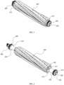
- FIG. 1 which representatively shows a three-dimensional schematic structural diagram of a cleaning brush proposed by the present application.
- the cleaning brush proposed by the present application is illustrated by taking application to an intelligent cleaning robot as an example. It is easy for those skilled in the art to understand that various modifications, additions, substitutions, deletions or other changes made to the following specific embodiments in order to apply relevant designs of the present application to other types of cleaning devices are still within the scope of the principle of the cleaning brush proposed by the present application.
- the cleaning brush proposed by the present application mainly includes a shaft lever (the shaft lever 100 shown in FIG. 2 ), the cylindrical member 200 and two end portion members 300.
- FIG. 2 representatively shows a three-dimensional exploded schematic diagram of the cleaning brush
- FIG. 3 representatively shows a front view of FIG. 1
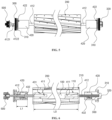
- FIG. 4 representatively shows a shaft-side section view of FIG. 3
- FIG. 5 representatively shows a front view of FIG. 2
- FIG. 6 representatively shows a shaft-side section view of FIG. 5
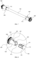
- FIG. 7 representatively shows a three-dimensional schematic structural diagram of the shaft lever 100 and the end portion members 300; and
- FIG. 1 representatively shows a three-dimensional exploded schematic diagram of the cleaning brush
- FIG. 3 representatively shows a front view of FIG. 1
- FIG. 4 representatively shows a shaft-side section view of FIG. 3
- FIG. 5 representatively shows a front view of FIG. 2
- FIG. 6 representatively shows a shaft-side section view of FIG. 5
- FIG. 7
- FIG. 8 representatively shows an enlarged exploded schematic diagram of part of the structure shown in FIG. 7 , which specifically shows an exploded state of one end portion member 300 and one first end portion 110 of the shaft lever.
- the shaft lever 100 has two first end portions 110 that are opposite in an axial direction, that is, two ends of the shaft lever 100 are the first end portions 110 respectively.
- the cylindrical member 200 is sleeved onto the shaft lever 100 coaxially; and the cylindrical member 200 has two second end portions 210 that are opposite in an axial direction, that is, two ends of the cylindrical member 200 are the second end portions 210 respectively.
- a brush part is arranged on the outer surface of the cylindrical member 200.
- the two end portion members 300 are mounted at the two first end portions 110 of the shaft lever 100 respectively.
- Each end portion member 300 has a blocking structure 310.
- the blocking structure 310 may prevent entanglements such as hair or silk threads from excessively extending away from the cleaning brush.
- the end portion member 300 and the corresponding first end portion 110 respectively have mutually matched mounting structures 400.
- the mounting structure 400 includes a guide sleeve 420 arranged at one end of the end portion member 300 facing the shaft lever 100, and the guide sleeve 420 may be sleeved onto the first end portion 110 of the shaft lever 100 corresponding to the end portion member 300.
- the second end portion 210 of the cylindrical member 200 corresponding to the end portion member 300 covers at least a portion of the guide sleeve.
- a coverage area A shown in FIG. 4 For details, reference may be made to a coverage area A shown in FIG. 4 .
- the present application allows at least a portion of the guide sleeve 420 to intervene between the shaft lever 100 and the corresponding end portion of the cylindrical member 200 to make entanglements wound around the cylindrical member 200 be mainly wound around the guide sleeve 420 rather than being directly wound around the shaft lever 100, so that the entanglements can be removed along with the disassembly of the end portion member 300, and cleaning is more convenient. Furthermore, during an assembling process of the cleaning brush, when the end portion members 300 are not assembled, component missing of the cleaning brush is apparent and is easier to be found.
- the embodiments in this specification are illustrated respectively with each of the two first end portions 110 of the shaft lever 100 being provided with the end portion member 300 as an example. It should be understood that the present application may also allow the end portion member 300 to be mounted on only one first end portion 110 of the shaft lever 100 in some embodiments. In other words, in various possible embodiments that conform to the design conception of the present application, the cleaning brush proposed by the present application includes at least one end portion member 300, and the at least one end member 300 is mounted on at least one first end portion 110 of the shaft lever 100.
- the second end portion 210 of the cylindrical member 200 corresponding to the end portion member 300 may cover the first end portion 110 on which the corresponding end portion member 300 is mounted.
- the first end portion 110, on which the end portion member 300 is mounted is entirely disposed within the coverage of the second end portion 210 corresponding to the first end portion 110, that is, the first end portion 110 do not stretch out of the second end portion 210, that is, the shaft lever 100 is shorter than the cylindrical member 200.
- the first end portion 110 on which the end portion member 300 is mounted, may also partially stretch out of the coverage of the corresponding second end portion 210, that is, the first end portion 110 may stretch out of the coverage area A shown in FIG. 4 .
- the configuration of the first end portion is not limited to this embodiment, and it is only needed to ensure that the second end portion 210 covers at least a portion of the end portion member 300.
- the blocking structure 310 of the end portion member 300 may be disposed outside the second end portion 210 of the cylindrical member 200 corresponding to the end portion member 300. In other words, the blocking structure 310 of the end portion member 300 may be disposed outside the coverage area A shown in FIG. 4 .
- the mounting structure 400 may include a guide hole 411 and a guide shaft 412.
- the guide hole 411 is coaxial with the first end portion 110 and is formed in an end face of the first end portion 110.
- the guide shaft 412 is connected with the end portion member 300, and used to be inserted in the guide hole 411.
- the present application may provide an axial guiding function and a radial limiting function in the mounting of the end portion member 300 and the shaft lever 100 by using the guide shaft 412 and the guide hole 411, which are in plug-in fit with each other.
- the mounting structures 400 may also include a guide sleeve 420.
- the guide sleeve 420 is arranged at one end of the end portion member 300 facing the shaft lever 100 and may be sleeved onto the first end portion 110.
- a first limiting structure is arranged on a side wall of the first end portion, and a second limiting structure matched with the first limiting structure is arranged on an inner wall of the guide sleeve 420. Accordingly, the cleaning brush may avoid relative rotation between the shaft lever 100 and the end portion member 300 through the matching of the first limiting structure and the second limiting structure.
- the mounting structure 400 may include the guide hole 411, the guide shaft 412 and the guide sleeve 420 at the same time.
- the guide sleeve 420 may be arranged around at least partial sections of the guide shaft 412 with one or more gaps.
- the mounting structure 400 may only include the guide hole 411 and the guide shaft 412, or may only include the guide sleeve 420. The mounting and fixing of the end portion member 300 and the first end portion 110 of the shaft lever 100 may be achieved through other structures.
- a distance L1 between one end of the guide sleeve 420 far away from a main body and the blocking structure 310 corresponding to the same first end portion 110 as the guide sleeve 420 may be greater than 5% (for example, 5%, 8%, 10%, 15%, etc.) of a length L0 of the shaft lever 100.
- the design in the present application that the guide sleeve 420 partially intervenes between the first end portion 110 and the second end portion 210 can make the end portion member 300 has a larger size (including the size of the guide sleeve 420), so as to enlarge the space of the end portion member 300 for winding of the entanglements, and further prevent the entanglements from winding around the shaft lever 100.
- the present application adopts the design of the length relationship of the above related members, so that the part of the end portion member 300 matched with the shaft lever 100 is prolonged, the size is increased, and the processing and production are easy.
- the first limiting structure may be a limiting groove 431, and the second limiting structure may be a limiting rib 432, and the limiting groove 431 is matched with the limiting rib 432 in shape. Accordingly, in a process of sleeving the first end portion 110 of the shaft lever 100 with the guide sleeve 420, the limiting rib 432 is matched with the limiting groove 431 and may provide guiding and limiting functions in the above mounting process.
- the first limiting structure may also be the limiting rib 432, and the second limiting structure may also be the limiting groove 431.
- one of the first limiting structure and the second limiting structure may be the limiting rib 432, while the other may be the limiting groove 431 matched with the limiting rib 432 in shape.
- the first limiting structure and the second limiting structure may also adopt limiting fit structures in other forms, and are not limited to the above embodiments.
- the limiting rib 432 and the limiting groove 431 may have matched spiral shapes. Accordingly, the end portion member 300 and the shaft lever 100 are relatively displaced in the axial direction and relatively rotated in the circumferential direction during dismounting and mounting of the end portion member 300 and the shaft lever 100.
- the spiral directions of the spiral limiting rib 432 and the spiral limiting groove 431 may be opposite to the rotation direction of the shaft lever 100.
- the spiral directions of the limiting rib 432 and the limiting groove 431 are opposite to the rotation direction of the shaft lever 100, when the shaft lever 100 rotates in the cleaning device in the rotation direction, looseness of the limiting rib 432 and the limiting groove 431 may be further avoided to ensure the mounting stability and reliability of the shaft lever 100 and the end portion member 300.
- the outer wall of the guide sleeve 420 may be provided with at least one first assembly mark 421.
- the first assembly mark 421 may mark the rotation direction of the end portion member 300 when assembling with the shaft lever 100 (i.e., the spiral directions of the limiting rib 432 and the limiting groove 431).
- FIG. 9 representatively shows an enlarged exploded schematic diagram of part of the structure of a cleaning brush proposed by the present application according to another embodiment, and specifically shows an exploded state of one end portion member 300 and one first end portion 110 of the shaft lever.
- the present application can provide a good feel in disassembly and assembly and a function of judging whether the assembly is in place through the fastening of the bump fastener 441 and the fastening groove 442, simplify the difficulty of disassembly and assembly, provide a certain fool-proofing effect, and further improve the user experience.
- the plurality of second limiting structures and the plurality of fourth limiting structures may be arranged uniformly at intervals in the circumferential direction of the shaft lever 100.
- the present application can make the limiting structures be stressed more uniformly during the process that the end portion member 300 transmits torque to the shaft lever 100.
- the bump fastener 441 when the fourth limiting structure is the bump fastener 441, the bump fastener 441 may be arranged on the inner wall of the guide sleeve 420 by an integral forming process. In some embodiments, the bump fastener 441 may also be arranged on the inner wall of the guide sleeve 420 by other processes, for example, by welding, or by stamping a partial structure of the guide sleeve 420. Furthermore, when the fourth limiting structure is the limiting groove 442, the limiting groove 442 may be a groove formed in the inner wall of the guide sleeve 420 or a through groove penetrating through the guide sleeve 420.
- the blocking structure 310 of the end portion member 300 may be a blocking ring, and the blocking ring may surround the end portion member 300 and forms a closed-ring structure.
- both first end portions 110 of the shaft lever 100 are provided with the end portion members 300.
- one of the two end portion members 300 is provided with the transmission structure 320 which is used for transmitting torque, and the other of the two end portion members 300 is used for mounting the bearing structure 500.
- the end portion member 300 provided with the transmission structure 320 is used to be connected with a driving mechanism of the cleaning device through the transmission structure 320
- the end portion member 300 provided with the bearing structure 500 is used to be connected rotatably with other structures (for example, a machine body) of the cleaning device through the bearing structure 500.
- the end portion member 300 i.e., a driving-side end cap
- the driving-side end cap rotates around the guide hole 411, and the driving-side end cap may move in the axial direction while rotating due to the spiral limiting groove 431 and the spiral limiting rib 432, so as to complete the assembly and disassembly of the entire end cap.
- the end portion member 300 i.e., a bearing-side end cap
- the bearing-side end cap can be mounted and dismounted according to the same movement logic.
- the transmission structure 320 may include a columnar structure with a regular polygonal cross section, the axis of the columnar structure coincides with those of the end portion member 300 and the shaft lever 100, and accordingly the transmission structure 320 may be used to be matched with an output end of a driving mechanism, for example, a final output gear of a gearbox.
- the matching section 4121 of the guide shaft 412 may be provided with a positioning groove 4122 in a circumferential direction, for example, the outer diameter of the matching section 4121 is designed to be smaller than those of other sections of the guide shaft 412 to make the matching section 4121 form the positioning groove 4122. Based on this, the positioning groove 4122 is in positioning fit with the bearing structure 500 to prevent displacement of the bearing structure 500.
- the cylindrical member 200 may be a flexible member or a rigid member.
- the brush part may be arranged on the outer surface of the cylindrical member 200 by bonding, inserting or the like.
- the brush part may also be integrally formed with the cylindrical member 200.
- the brush part may also be in other forms, for example, in the form of blades or bristles.
- the limiting rib and the limiting groove may be matched in shape, and each of the limiting rib and the limiting groove may have a linear shape or a spiral shape.
- the second limiting structure is the limiting rib; and the limiting rib is arranged on the inner wall of the guide sleeve by a welding or integral forming process, or is formed by a partial structure of the guide sleeve by a stamping process.
- the second limiting structure is the limiting groove, and the limiting groove is a groove formed in the inner wall of the guide sleeve or a through groove penetrating through the guide sleeve.
- the first end portion is provided with a plurality of first limiting structures, and the plurality of first limiting structures are arranged uniformly at intervals in the circumferential direction of the shaft lever.
- the guide sleeve is provided with a plurality of second limiting structures, and the plurality of second limiting structures are arranged uniformly at intervals in the circumferential direction of the guide sleeve.
- the first end portion is provided with a plurality of first limiting structures and a plurality of third limiting structures, of which the numbers are equal, wherein the plurality of first limiting structures and the plurality of third limiting structures are arranged alternately in sequence at intervals in the circumferential direction of the shaft lever.
- the plurality of first limiting structures and the plurality of third limiting structures are arranged uniformly at intervals in the circumferential direction of the shaft lever.
- the guide sleeve is provided with a plurality of second limiting structures and a plurality of fourth limiting structures, of which the numbers are equal, wherein the plurality of second limiting structures and the plurality of fourth limiting structures are arranged alternately in sequence at intervals in the circumferential direction of the guide sleeve.
- the plurality of second limiting structures and the plurality of fourth limiting structures are arranged uniformly at intervals in the circumferential direction of the guide sleeve.
- the fourth limiting structure is a bump fastener; and the bump fastener is arranged on the inner wall of the guide sleeve by a welding or integral forming process, or is formed by a partial structure of the guide sleeve by a stamping process.
- the fourth limiting structure is a fastening groove, and the fastening groove is a groove formed in the inner wall of the guide sleeve or a through groove penetrating through the guide sleeve.
- the transmission structure includes a columnar structure with a regular polygonal cross section, the axis of the columnar structure coincides with those of the end portion member and the shaft lever, and the transmission structure is used to be matched with an output end of a driving mechanism.
- one end of the guide shaft of one end portion member facing away from the shaft lever stretches out of the end portion member to serve as a matching section matched with the bearing structure; and the bearing structure is detachably arranged on the matching section of the guide shaft.
- a positioning groove is formed in the matching section in a circumferential direction; the positioning groove is in positioning fit with the bearing structure to prevent displacement of the bearing structure.
- the cylindrical member may be a flexible member or a rigid member.
- the intelligent cleaning device proposed by the present application includes the cleaning brush proposed by the present application and described in the above embodiments.
- the cleaning brush proposed by the present application includes the shaft lever 100, the cylindrical member 200 and the end portion member 300.
- the end portion member 300 is mounted at the first end portion 110 of the shaft lever 100 and has the blocking structure 310 used to prevent the entanglements from excessively extending away from the cleaning brush.
- the end portion member 300 and the first end portion 110 have mutually matched mounting structures 400 respectively.
- the mounting structure 400 includes the guide sleeve 420 arranged at one end of the end portion member 300 facing the shaft lever 100.
- the guide sleeve 420 is used to be sleeved onto the first end portion 110 of the shaft lever 100.
- the second end portion 210 of the cylindrical member 200 corresponding to the end portion member 300 covers at least a portion of the guide sleeve 420.
- the present application allows at least a portion of the guide sleeve 420 to intervene between the shaft lever 100 and the corresponding end portion of the cylindrical member 200 to make the entanglements wound around the cylindrical member 200 be wound around the guide sleeve 420 rather than being directly wound around the shaft lever 100, so that the entanglements can be removed along with the disassembly of the end portion member 300, and cleaning is more convenient.
Landscapes
- Engineering & Computer Science (AREA)
- Mechanical Engineering (AREA)
- Manufacturing & Machinery (AREA)
- Mutual Connection Of Rods And Tubes (AREA)
- Cleaning In General (AREA)
- Brushes (AREA)
Abstract
Description
- This application is based on and claims priority of the
Chinese Patent Application No. 202220052838.5, filed on January 10, 2022 - This application relates to the field of cleaning devices, and in particular, to a cleaning brush and an intelligent cleaning device.
- A cleaning brush is an important functional component of a cleaning device. End caps of the cleaning brush are used for blocking entanglements such as hair or silk threads that are wound around the cleaning device during a working process, so as to avoid the phenomenon that the entanglements extend excessively to end portions of the cleaning brush to be wound around a power output end and a bearing end of a motor so that the power output end and the bearing end of the motor are stuck.
- End caps of an existing cleaning brush are small in size, longer end portions of a shaft lever of the cleaning brush are exposed outside the end caps, and the end caps are located outside a cylindrical member that sleeves the shaft lever of the cleaning brush, so that entanglements wound around the cylindrical member are easily wound from end portions of the cylindrical member to the end portions of the shaft lever to deeper positions, and the end caps have to be disassembled to take the entanglements out of the cylindrical member, wasting time and energy. Furthermore, since the end caps of the existing cleaning brush are small in size, an omission of the end caps is difficult to be found if it happens during an assembling process of the cleaning brush, and thus it is necessary to set up an additional omission prevention structure.
- A main purpose of the present disclosure is to overcome at least one of above defects of the prior art by providing a cleaning brush that can prevent entanglements from being wound to a shaft lever to a limited extent and allows the entanglements to be removed more conveniently.
- Another main purpose of the present disclosure is to overcome at least one of above defects of the prior art by providing an intelligent cleaning device using the cleaning brush.
- To achieve the above purposes, the present disclosure adopts the following technical schemes:
according to an aspect of this application, a cleaning brush is provided, wherein the cleaning brush includes a shaft lever, a cylindrical member and at least one end portion member; the shaft lever has two first end portions that are opposite in an axial direction, and at least one first limiting structure is arranged on a side wall of the first end portion; the cylindrical member is coaxial with and sleeved onto the shaft lever, and has two second end portions that are opposite in the axial direction, and a brush part is arranged on the outer surface of the cylindrical member; the at least one end portion member is mounted on at least one of the two first end portions, the end portion member has a blocking structure for preventing entanglements from excessively extending away from the cleaning brush, the end portion member and the first end portion have mounting structures respectively, the mounting structures being mutually matched, the mounting structure includes a guide sleeve arranged at one end of the end portion member facing the shaft lever, and configured to be sleeved onto the first end portion; and the second end portion of the cylindrical member corresponding to the end portion member covers at least a portion of the guide sleeve arranged at the one end of the corresponding end portion member facing the shaft lever. - According to an embodiment of this application, the second end portion of the cylindrical member corresponding to the end portion member covers the first end portion on which the corresponding end portion member is mounted.
- According to an embodiment of the present disclosure, the blocking structure of the end portion member is disposed outside the second end portion of the cylindrical member corresponding to the end portion member.
- According to an embodiment of this application, the mounting structure further includes a guide hole and a guide shaft; the guide hole is coaxial with the first end portion and formed in an end face of the first end portion; and the guide shaft is connected to the end portion member, and the guide shaft is used to be inserted in the guide hole.
- According to an embodiment of this application, in the axial direction of the shaft lever, a distance between one end of the guide sleeve far away from a main body and the blocking structure is greater than 5% of the length of the shaft lever, the guide sleeve and the blocking structure corresponding to a same first end portion.
- According to an embodiment of this application, the at least one first limiting structure is arranged on the side wall of the first end portion, and at least one second limiting structure matched with the at least one first limiting structure is arranged on an inner wall of the guide sleeve, wherein one of the first limiting structure and the second limiting structure is a limiting rib, and the other one of the first limiting structure and the second limiting structure is a limiting groove; and the limiting rib is matched with the limiting groove in shape.
- According to an embodiment of this application, at least one third limiting structure is arranged on the side wall of the first end portion, and at least one fourth limiting structure matched with the at least one third limiting structure is arranged on the inner wall of the guide sleeve, wherein one of the third limiting structure and the fourth limiting structure is a bump fastener, and the other one of the third limiting structure and the fourth limiting structure is a fastening groove in fastening fit with the bump fastener.
- According to an embodiment of this application, the limiting rib and the limiting groove are matched in shape, and each of the limiting rib and the limiting groove has a linear shape or a spiral shape.
- According to an embodiment of this application, the second limiting structure is the limiting rib; and the limiting rib is arranged on the inner wall of the guide sleeve by a welding or integral forming process, or is formed by a partial structure of the guide sleeve by a stamping process. Alternatively, the second limiting structure is the limiting groove, and the limiting groove is a groove formed in the inner wall of the guide sleeve or a through groove penetrating through the guide sleeve.
- According to an embodiment of this application, the first end portion is provided with a plurality of first limiting structures arranged uniformly at intervals in a circumferential direction of the shaft lever.
- According to an embodiment of this application, the guide sleeve is provided with a plurality of second limiting structures arranged uniformly at intervals in a circumferential direction of the guide sleeve.
- According to an embodiment of this application, the end portion member and the guide sleeve are integrally formed.
- According to an embodiment of this application, the first end portion is provided with a plurality of first limiting structures and a plurality of third limiting structures, of which the numbers are equal, wherein the plurality of first limiting structures and the plurality of third limiting structures are arranged alternately in sequence at intervals in the circumferential direction of the shaft lever.
- According to an embodiment of this application, the plurality of first limiting structures and the plurality of third limiting structures are arranged uniformly at intervals in the circumferential direction of the shaft lever.
- According to an embodiment of this application, the guide sleeve is provided with a plurality of second limiting structures and a plurality of fourth limiting structures, of which the numbers are equal, wherein the plurality of second limiting structures and the plurality of fourth limiting structures are arranged alternately in sequence at intervals in the circumferential direction of the guide sleeve.
- According to an embodiment of this application, the plurality of second limiting structures and the plurality of fourth limiting structures are arranged uniformly at intervals in the circumferential direction of the guide sleeve.
- According to an embodiment of this application, the fourth limiting structure is a bump fastener; and the bump fastener is arranged on the inner wall of the guide sleeve by a welding or integral forming process, or is formed by a partial structure of the guide sleeve by a stamping process. Alternatively, the fourth limiting structure is a fastening groove, and the fastening groove is a groove formed in the inner wall of the guide sleeve or a through groove penetrating through the guide sleeve.
- According to an embodiment of this application, at least one second assembly mark is arranged on an outer wall of the guide sleeve; and a position of the at least one second assembly mark corresponds to a position of the at least one second limiting structure to mark the position of the at least one second limiting structure.
- According to an embodiment of this application, the blocking structure is a blocking ring, and the blocking ring surrounds the end portion member and forms a closed-ring structure.
- According to an embodiment of this application, each of the two first end portions of the shaft lever is mounted with the end portion member; and one of the two end portion members is provided with a transmission structure, and the other one of the two end portion members is configured for mounting a bearing structure.
- According to an embodiment of this application, the transmission structure includes a columnar structure with a regular polygonal cross section, an axis of the columnar structure coincides with axis of the end portion member and the shaft lever, and the transmission structure is used to be matched with an output end of a driving mechanism.
- According to an embodiment of this application, one end of the guide shaft of one end portion member facing away from the shaft lever stretches out of the end portion member to serve as a matching section matched with the bearing structure; and the bearing structure is detachably arranged on the matching section of the guide shaft.
- According to an embodiment of this application, a positioning groove is formed in the matching section in a circumferential direction; the positioning groove is in positioning fit with the bearing structure to prevent displacement of the bearing structure.
- According to an embodiment of this application, the cylindrical member is a flexible member or a rigid member.
- According to another aspect of this application, an intelligent cleaning device is provided, wherein the intelligent cleaning device includes the cleaning brush proposed by this application and described in the above embodiments.
- The cleaning brush proposed by this application includes the shaft lever, the cylindrical member and the end portion member. The end portion member is mounted at a first end portion of the shaft lever and has a blocking structure. The blocking structure is used to prevent entanglements from excessively extending away from the cleaning brush. The end portion member is provided with a guide sleeve, and the guide sleeve is used to be sleeved onto the first end portion. A second end portion of the cylindrical member corresponding to the end portion member covers at least a portion of the guide sleeve arranged at one end of the end portion member facing the shaft lever. Through the above design, this application allows at least a portion of the guide sleeve to intervene between the shaft lever and the corresponding end portion of the cylindrical member to make entanglements wound around the cylindrical member be wound around the guide sleeve rather than being directly wound around the shaft lever, so that the entanglements can be removed along with the disassembly of the end portion member, and cleaning is more convenient.
- The various objectives, features and advantages of this application will become more apparent by considering the following detailed description of preferred embodiments of the present disclosure with reference to the accompanying drawings. The accompanying drawings are merely exemplary illustrations of the present disclosure and are not necessarily drawn to scale. In the accompanying drawings, the same reference numerals always indicate the same or similar components.
-
FIG. 1 shows a three-dimensional schematic structural diagram of a cleaning brush according to an exemplary embodiment. -
FIG. 2 shows a three-dimensional exploded schematic diagram of the cleaning brush shown inFIG. 1 . -
FIG. 3 is a front view ofFIG. 1 . -
FIG. 4 is a shaft-side section view ofFIG. 3 . -
FIG. 5 is a front view ofFIG. 2 . -
FIG. 6 is a shaft-side section view ofFIG. 5 . -
FIG. 7 shows a three-dimensional schematic structural diagram of a shaft lever and end portion members of a cleaning brush shown inFIG. 1 . -
FIG. 8 is an enlarged exploded schematic diagram of part of the structure shown inFIG. 7 . -
FIG. 9 is an enlarged exploded schematic diagram of part of a structure of a cleaning brush according to an exemplary embodiment. - Exemplary embodiments embodying the features and advantages of this application are described in detail in the following descriptions. It should be understood that the present disclosure may have various changes in different embodiments, which are all included within the scope of the present disclosure, and that the descriptions and accompanying drawings therein are intended to illustrate rather than limit this application.
- In the following description of different exemplary implementations of the present application, reference is made to the accompanying drawings, which form part of the present disclosure, and in which different exemplary structures, systems, and steps that may implement aspects of the present application are shown by way of examples. It should be understood that other specific schemes of components, structures, exemplary devices, systems and steps may be used, and structural and functional modifications may be made without departing from the scope of the present disclosure. Moreover, although the terms "above", "between", "within" and the like may be used in this specification to describe different exemplary features and elements of the present application, these terms are used herein for convenience only, for example, according to the directions of the examples described in the accompanying drawings. Anything in this specification should not be construed as requiring a particular three-dimensional orientation of a structure to fall within the scope of the present disclosure.
- Referring to
FIG. 1 , which representatively shows a three-dimensional schematic structural diagram of a cleaning brush proposed by the present application. In this exemplary embodiment, the cleaning brush proposed by the present application is illustrated by taking application to an intelligent cleaning robot as an example. It is easy for those skilled in the art to understand that various modifications, additions, substitutions, deletions or other changes made to the following specific embodiments in order to apply relevant designs of the present application to other types of cleaning devices are still within the scope of the principle of the cleaning brush proposed by the present application. - As shown in
FIG. 1 , in this embodiment, the cleaning brush proposed by the present application mainly includes a shaft lever (theshaft lever 100 shown inFIG. 2 ), thecylindrical member 200 and twoend portion members 300. With reference toFIGS. 2-8 ,FIG. 2 representatively shows a three-dimensional exploded schematic diagram of the cleaning brush;FIG. 3 representatively shows a front view ofFIG. 1 ;FIG. 4 representatively shows a shaft-side section view ofFIG. 3 ;FIG. 5 representatively shows a front view ofFIG. 2 ;FIG. 6 representatively shows a shaft-side section view ofFIG. 5 ;FIG. 7 representatively shows a three-dimensional schematic structural diagram of theshaft lever 100 and theend portion members 300; andFIG. 8 representatively shows an enlarged exploded schematic diagram of part of the structure shown inFIG. 7 , which specifically shows an exploded state of oneend portion member 300 and onefirst end portion 110 of the shaft lever. Structures, connection ways and functional relationships of main components of the cleaning brush proposed by the present application are described in detail hereinafter with reference to the accompanying drawings. - As shown in
FIGS. 1-4 , in an embodiment of the present application, theshaft lever 100 has twofirst end portions 110 that are opposite in an axial direction, that is, two ends of theshaft lever 100 are thefirst end portions 110 respectively. Thecylindrical member 200 is sleeved onto theshaft lever 100 coaxially; and thecylindrical member 200 has twosecond end portions 210 that are opposite in an axial direction, that is, two ends of thecylindrical member 200 are thesecond end portions 210 respectively. A brush part is arranged on the outer surface of thecylindrical member 200. The twoend portion members 300 are mounted at the twofirst end portions 110 of theshaft lever 100 respectively. Eachend portion member 300 has a blockingstructure 310. The blockingstructure 310 may prevent entanglements such as hair or silk threads from excessively extending away from the cleaning brush. Moreover, theend portion member 300 and the correspondingfirst end portion 110 respectively have mutually matched mountingstructures 400. The mountingstructure 400 includes aguide sleeve 420 arranged at one end of theend portion member 300 facing theshaft lever 100, and theguide sleeve 420 may be sleeved onto thefirst end portion 110 of theshaft lever 100 corresponding to theend portion member 300. On this basis, thesecond end portion 210 of thecylindrical member 200 corresponding to theend portion member 300 covers at least a portion of the guide sleeve. For details, reference may be made to a coverage area A shown inFIG. 4 . Through the above design, the present application allows at least a portion of theguide sleeve 420 to intervene between theshaft lever 100 and the corresponding end portion of thecylindrical member 200 to make entanglements wound around thecylindrical member 200 be mainly wound around theguide sleeve 420 rather than being directly wound around theshaft lever 100, so that the entanglements can be removed along with the disassembly of theend portion member 300, and cleaning is more convenient. Furthermore, during an assembling process of the cleaning brush, when theend portion members 300 are not assembled, component missing of the cleaning brush is apparent and is easier to be found. - It should be noted that the embodiments in this specification are illustrated respectively with each of the two
first end portions 110 of theshaft lever 100 being provided with theend portion member 300 as an example. It should be understood that the present application may also allow theend portion member 300 to be mounted on only onefirst end portion 110 of theshaft lever 100 in some embodiments. In other words, in various possible embodiments that conform to the design conception of the present application, the cleaning brush proposed by the present application includes at least oneend portion member 300, and the at least oneend member 300 is mounted on at least onefirst end portion 110 of theshaft lever 100. - As shown in
FIGS. 2 ,4 and6 , in an embodiment of the present application, thesecond end portion 210 of thecylindrical member 200 corresponding to theend portion member 300 may cover thefirst end portion 110 on which the correspondingend portion member 300 is mounted. In other words, thefirst end portion 110, on which theend portion member 300 is mounted, is entirely disposed within the coverage of thesecond end portion 210 corresponding to thefirst end portion 110, that is, thefirst end portion 110 do not stretch out of thesecond end portion 210, that is, theshaft lever 100 is shorter than thecylindrical member 200. In some embodiments, thefirst end portion 110, on which theend portion member 300 is mounted, may also partially stretch out of the coverage of the correspondingsecond end portion 210, that is, thefirst end portion 110 may stretch out of the coverage area A shown inFIG. 4 . Thus, the configuration of the first end portion is not limited to this embodiment, and it is only needed to ensure that thesecond end portion 210 covers at least a portion of theend portion member 300. - As shown in
FIGS. 1-6 , in an embodiment of the present application, the blockingstructure 310 of theend portion member 300 may be disposed outside thesecond end portion 210 of thecylindrical member 200 corresponding to theend portion member 300. In other words, the blockingstructure 310 of theend portion member 300 may be disposed outside the coverage area A shown inFIG. 4 . - As shown in
FIGS. 2 ,4 and6 , in an embodiment of the present application, the mountingstructure 400 may include aguide hole 411 and aguide shaft 412. Specifically, theguide hole 411 is coaxial with thefirst end portion 110 and is formed in an end face of thefirst end portion 110. Theguide shaft 412 is connected with theend portion member 300, and used to be inserted in theguide hole 411. Through the above design, the present application may provide an axial guiding function and a radial limiting function in the mounting of theend portion member 300 and theshaft lever 100 by using theguide shaft 412 and theguide hole 411, which are in plug-in fit with each other. - As shown in
FIGS. 1-6 , in an embodiment of the present application, the mountingstructures 400 may also include aguide sleeve 420. Specifically, theguide sleeve 420 is arranged at one end of theend portion member 300 facing theshaft lever 100 and may be sleeved onto thefirst end portion 110. On this basis, a first limiting structure is arranged on a side wall of the first end portion, and a second limiting structure matched with the first limiting structure is arranged on an inner wall of theguide sleeve 420. Accordingly, the cleaning brush may avoid relative rotation between theshaft lever 100 and theend portion member 300 through the matching of the first limiting structure and the second limiting structure. - Furthermore, as shown in
FIGS. 2 ,4 and6 , in an embodiment of the present application, the mountingstructure 400 may include theguide hole 411, theguide shaft 412 and theguide sleeve 420 at the same time. On this basis, theguide sleeve 420 may be arranged around at least partial sections of theguide shaft 412 with one or more gaps. In some embodiments, the mountingstructure 400 may only include theguide hole 411 and theguide shaft 412, or may only include theguide sleeve 420. The mounting and fixing of theend portion member 300 and thefirst end portion 110 of theshaft lever 100 may be achieved through other structures. - As shown in
FIG. 6 , according to an embodiment of the present application, in the axial direction of theshaft lever 100, a distance L1 between one end of theguide sleeve 420 far away from a main body and the blockingstructure 310 corresponding to the samefirst end portion 110 as theguide sleeve 420 may be greater than 5% (for example, 5%, 8%, 10%, 15%, etc.) of a length L0 of theshaft lever 100. Accordingly, compared with the design that the end caps of the existing cleaning brush are smaller in size, the design in the present application that theguide sleeve 420 partially intervenes between thefirst end portion 110 and thesecond end portion 210 can make theend portion member 300 has a larger size (including the size of the guide sleeve 420), so as to enlarge the space of theend portion member 300 for winding of the entanglements, and further prevent the entanglements from winding around theshaft lever 100. In other words, the present application adopts the design of the length relationship of the above related members, so that the part of theend portion member 300 matched with theshaft lever 100 is prolonged, the size is increased, and the processing and production are easy. - As shown in
FIGS. 6 and8 , in an embodiment of the present application, the first limiting structure may be a limitinggroove 431, and the second limiting structure may be a limitingrib 432, and the limitinggroove 431 is matched with the limitingrib 432 in shape. Accordingly, in a process of sleeving thefirst end portion 110 of theshaft lever 100 with theguide sleeve 420, the limitingrib 432 is matched with the limitinggroove 431 and may provide guiding and limiting functions in the above mounting process. In some embodiments, the first limiting structure may also be the limitingrib 432, and the second limiting structure may also be the limitinggroove 431. In other words, in various possible embodiments that conform to the design conception of the present application, one of the first limiting structure and the second limiting structure may be the limitingrib 432, while the other may be the limitinggroove 431 matched with the limitingrib 432 in shape. Furthermore, the first limiting structure and the second limiting structure may also adopt limiting fit structures in other forms, and are not limited to the above embodiments. - As shown in
FIGS. 6 and8 , in an embodiment of the present application, the limitingrib 432 and the limitinggroove 431 may have matched spiral shapes. Accordingly, theend portion member 300 and theshaft lever 100 are relatively displaced in the axial direction and relatively rotated in the circumferential direction during dismounting and mounting of theend portion member 300 and theshaft lever 100. - Based on the design that the limiting
rib 432 and the limitinggroove 431 have spiral shapes, in an embodiment of the present application, the spiral directions of thespiral limiting rib 432 and thespiral limiting groove 431 may be opposite to the rotation direction of theshaft lever 100. Through the above design, since the spiral directions of the limitingrib 432 and the limitinggroove 431 are opposite to the rotation direction of theshaft lever 100, when theshaft lever 100 rotates in the cleaning device in the rotation direction, looseness of the limitingrib 432 and the limitinggroove 431 may be further avoided to ensure the mounting stability and reliability of theshaft lever 100 and theend portion member 300. - As shown in
FIGS. 7 and 8 , based on the design that the limitingrib 432 and the limitinggroove 431 have spiral shapes, in an embodiment of the present application, the outer wall of theguide sleeve 420 may be provided with at least onefirst assembly mark 421. Thefirst assembly mark 421 may mark the rotation direction of theend portion member 300 when assembling with the shaft lever 100 (i.e., the spiral directions of the limitingrib 432 and the limiting groove 431). - As shown in
FIGS. 7 and 8 , based on the design that theguide sleeve 420 is provided with thefirst assembly mark 421, in an embodiment of the present application, the outer wall of theguide sleeve 420 may be provided with a deformation groove; and the deformation groove may prevent shrinkage deformation of injection molded parts such as theguide sleeve 420 and theend portion member 300. Based on this, the deformation groove may take a special shape (approximately a triangle shape or arrowhead shape, for example) to serve as thefirst assembly mark 421, so as to mark the rotation direction of theend portion member 300 when assembling with theshaft lever 100 while preventing shrinkage deformation. - Reference is made to
FIG. 9 , which representatively shows an enlarged exploded schematic diagram of part of the structure of a cleaning brush proposed by the present application according to another embodiment, and specifically shows an exploded state of oneend portion member 300 and onefirst end portion 110 of the shaft lever. - As shown in
FIG. 9 , in an embodiment of the present application, one of the first limiting structure and the second limiting structure may be the limitingrib 432, while the other may be the limitinggroove 431. Based on this, the limitingrib 432 and the limitinggroove 431 may have linear shapes matched with each other. - As shown in
FIGS. 4 and6 , in an embodiment of the present application, when the second limiting structure is the limitingrib 432, the limitingrib 432 may be arranged on the inner wall of theguide sleeve 420 by an integral forming process. In some embodiments, the limitingrib 432 may also be arranged on the inner wall of theguide sleeve 420 by other processes, for example, by welding, or by stamping a partial structure of theguide sleeve 420. Furthermore, when the second limiting structure is the limitinggroove 431, the limitinggroove 431 may be a groove formed in the inner wall of theguide sleeve 420 or a through groove penetrating through theguide sleeve 420. - In an embodiment of the present application, the
first end portion 110 may be provided with a plurality of first limiting structures, which are arranged uniformly at intervals in the circumferential direction of theshaft lever 100. - In an embodiment of the present application, the
guide sleeve 420 may be provided with a plurality of second limiting structures, which are arranged uniformly at intervals in the circumferential direction of theguide sleeve 420. - As described above, with the first limiting structure and the second limiting structure being the limiting
groove 431 and the limitingrib 432 respectively as an example, there may be one or more limitingribs 432 in case of a plurality of limitinggrooves 431, and the number of the limitingribs 432 is not greater than but may be less than that of the limitinggrooves 431. - As shown in
FIGS. 7 and 8 , in an embodiment of the present application, a third limiting structure may be arranged on the side wall of thefirst end portion 110, and a fourth limiting structure matched with the third limiting structure may be arranged on the inner wall of theguide sleeve 420. Based on this, one of the third limiting structure and the fourth limiting structure may be abump fastener 441, while the other may be afastening groove 442 in fastening fit with thebump fastener 441. Through the above design, the present application can provide a good feel in disassembly and assembly and a function of judging whether the assembly is in place through the fastening of thebump fastener 441 and thefastening groove 442, simplify the difficulty of disassembly and assembly, provide a certain fool-proofing effect, and further improve the user experience. - In an embodiment of the present application, the
first end portion 110 of theshaft lever 100 may be provided with a plurality of first limiting structures and a plurality of third limiting structures, of which the numbers may be equal. Based on this, the plurality of first limiting structures and the plurality of third limiting structures may be arranged alternately in sequence at intervals in the circumferential direction of theshaft lever 100. - Based on the design that the
first end portion 110 of theshaft lever 100 is provided with the plurality of first limiting structures and the plurality of third limiting structures, of which the numbers are equal, in an embodiment of the present application, the plurality of first limiting structures and the plurality of third limiting structures may be arranged uniformly at intervals in the circumferential direction of theshaft lever 100. Through the above design, the present application can make the limiting structures be stressed more uniformly during a process that theend portion member 300 transmits torque to theshaft lever 100. - In an embodiment of the present application, the
guide sleeve 420 may be provided with a plurality of second limiting structures and a plurality of fourth limiting structures, of which the numbers may be equal. Based on this, the plurality of second limiting structures and the plurality of fourth limiting structures may be arranged alternately in sequence at intervals in the circumferential direction of theshaft lever 100. - Based on the design that the
guide sleeve 420 is provided with the plurality of second limiting structures and the plurality of fourth limiting structures, of which the numbers are equal, in an embodiment of the present application, the plurality of second limiting structures and the plurality of fourth limiting structures may be arranged uniformly at intervals in the circumferential direction of theshaft lever 100. Through the above design, the present application can make the limiting structures be stressed more uniformly during the process that theend portion member 300 transmits torque to theshaft lever 100. - As shown in
FIG. 8 , in an embodiment of the present application, when the fourth limiting structure is thebump fastener 441, thebump fastener 441 may be arranged on the inner wall of theguide sleeve 420 by an integral forming process. In some embodiments, thebump fastener 441 may also be arranged on the inner wall of theguide sleeve 420 by other processes, for example, by welding, or by stamping a partial structure of theguide sleeve 420. Furthermore, when the fourth limiting structure is the limitinggroove 442, the limitinggroove 442 may be a groove formed in the inner wall of theguide sleeve 420 or a through groove penetrating through theguide sleeve 420. - As shown in
FIGS. 5 and8 , in an embodiment of the present application, at least onesecond assembly mark 422 may be arranged on the outer wall of theguide sleeve 420; and the position of the at least onesecond assembly mark 422 may correspond to that of at least one second limiting structure to mark the position of the at least one second limiting structure. In some embodiments, when a plurality of second limiting structures are arranged on the inner wall of theguide sleeve 420, only onesecond assembly mark 422 corresponding to any second limiting structure may be arranged on the outer wall of theguide sleeve 420, or a plurality of second assembly marks 422 corresponding to the second limiting structures respectively may be arranged on the outer wall of theguide sleeve 420. - As shown in
FIGS. 1-6 , in an embodiment of the present application, the blockingstructure 310 of theend portion member 300 may be a blocking ring, and the blocking ring may surround theend portion member 300 and forms a closed-ring structure. - As shown in
FIGS. 1-7 , in an embodiment of the present application, bothfirst end portions 110 of theshaft lever 100 are provided with theend portion members 300. Based on this, one of the twoend portion members 300 is provided with thetransmission structure 320 which is used for transmitting torque, and the other of the twoend portion members 300 is used for mounting the bearingstructure 500. Based on this, theend portion member 300 provided with thetransmission structure 320 is used to be connected with a driving mechanism of the cleaning device through thetransmission structure 320, and theend portion member 300 provided with the bearingstructure 500 is used to be connected rotatably with other structures (for example, a machine body) of the cleaning device through the bearingstructure 500. Accordingly, when the end portion member 300 (i.e., a driving-side end cap) provided with thetransmission structure 320 is mounted, the driving-side end cap rotates around theguide hole 411, and the driving-side end cap may move in the axial direction while rotating due to thespiral limiting groove 431 and thespiral limiting rib 432, so as to complete the assembly and disassembly of the entire end cap. Similarly, when the end portion member 300 (i.e., a bearing-side end cap) for mounting the bearingstructure 500 is mounted, the bearing-side end cap can be mounted and dismounted according to the same movement logic. Meanwhile, since the spiral directions of thespiral limiting rib 432 and thespiral limiting groove 431 are opposite to the rotation direction (i.e., an operation direction of a main brush) of theshaft lever 100, spiral loosening is avoided during operation. Through the above design, during an assembling process of the cleaning brush, when theend portion members 300 are not assembled, matching structures (such as a laminated structure and the bearing structure 500 ) mounted or arranged on the twoend portion members 300 are not arranged, so that main brush parts (such as theshaft lever 100 and the cylindrical member 200) cannot be assembled in place when theend portion members 300 are omitted, and accordingly a more complete omission prevention function can be achieved. Furthermore, when bothfirst end portions 110 of theshaft lever 100 are provided with theend portion members 300, the same mountingstructures 400 are adopted between the twofirst end portions 110 of theshaft lever 100 and the twoend portion members 300, which facilitates error prevention during production, is beneficial to reducing the error rate of processing, and increases the production yield. - As shown in
FIGS. 1 and 2 , based on the design that oneend portion member 300 is provided with thetransmission structure 320, in an embodiment of the present application, thetransmission structure 320 may include a columnar structure with a regular polygonal cross section, the axis of the columnar structure coincides with those of theend portion member 300 and theshaft lever 100, and accordingly thetransmission structure 320 may be used to be matched with an output end of a driving mechanism, for example, a final output gear of a gearbox. - As shown in
FIGS. 2 and6 , based on the design that the otherend portion member 300 is provided with the bearingstructure 500, in an embodiment of the present application, one end of theguide shaft 412 of theend portion member 300 facing away from theshaft lever 100 stretches out of theend portion member 300 to serve as amatching section 4121 matched with the bearingstructure 500; and thebearing structure 500 is detachably arranged on thematching section 4121 of theguide shaft 412. - As shown in
FIGS. 5 and 6 , based on the design that theguide shaft 412 has thematching section 4121, in an embodiment of the present application, thematching section 4121 of theguide shaft 412 may be provided with apositioning groove 4122 in a circumferential direction, for example, the outer diameter of thematching section 4121 is designed to be smaller than those of other sections of theguide shaft 412 to make thematching section 4121 form thepositioning groove 4122. Based on this, thepositioning groove 4122 is in positioning fit with the bearingstructure 500 to prevent displacement of thebearing structure 500. - As shown in
FIGS. 8 and9 , in an embodiment of the present application, theend portion member 300 may be provided with afriction structure 330, such as, but not limited to, friction patterns, friction protrusions, etc., which makes theend portion member 300 be easier to be screwed in the assembling process. - In an embodiment of the present application, the
cylindrical member 200 may be a flexible member or a rigid member. Furthermore, the brush part may be arranged on the outer surface of thecylindrical member 200 by bonding, inserting or the like. When thecylindrical member 200 is the flexible member, the brush part may also be integrally formed with thecylindrical member 200. In some embodiments, the brush part may also be in other forms, for example, in the form of blades or bristles. - It should be noted here that the cleaning brush shown in the accompanying drawings and described in this specification are only a few examples of a number of kinds of cleaning brushes that may apply the principles of the present application. It should be clearly understood that the principles of the present application are not limited to any detail or any component of the cleaning brush shown in the accompanying drawings or described in this specification.
- In an embodiment of the present application, the limiting rib and the limiting groove may be matched in shape, and each of the limiting rib and the limiting groove may have a linear shape or a spiral shape.
- In an embodiment of the present application, the second limiting structure is the limiting rib; and the limiting rib is arranged on the inner wall of the guide sleeve by a welding or integral forming process, or is formed by a partial structure of the guide sleeve by a stamping process. Alternatively, the second limiting structure is the limiting groove, and the limiting groove is a groove formed in the inner wall of the guide sleeve or a through groove penetrating through the guide sleeve.
- In an embodiment of the present application, the first end portion is provided with a plurality of first limiting structures, and the plurality of first limiting structures are arranged uniformly at intervals in the circumferential direction of the shaft lever.
- In an embodiment of the present application, the guide sleeve is provided with a plurality of second limiting structures, and the plurality of second limiting structures are arranged uniformly at intervals in the circumferential direction of the guide sleeve.
- In an embodiment of the present application, the first end portion is provided with a plurality of first limiting structures and a plurality of third limiting structures, of which the numbers are equal, wherein the plurality of first limiting structures and the plurality of third limiting structures are arranged alternately in sequence at intervals in the circumferential direction of the shaft lever.
- In an embodiment of the present application, the plurality of first limiting structures and the plurality of third limiting structures are arranged uniformly at intervals in the circumferential direction of the shaft lever.
- In an embodiment of the present application, the guide sleeve is provided with a plurality of second limiting structures and a plurality of fourth limiting structures, of which the numbers are equal, wherein the plurality of second limiting structures and the plurality of fourth limiting structures are arranged alternately in sequence at intervals in the circumferential direction of the guide sleeve.
- In an embodiment of the present application, the plurality of second limiting structures and the plurality of fourth limiting structures are arranged uniformly at intervals in the circumferential direction of the guide sleeve.
- In an embodiment of the present application, the fourth limiting structure is a bump fastener; and the bump fastener is arranged on the inner wall of the guide sleeve by a welding or integral forming process, or is formed by a partial structure of the guide sleeve by a stamping process. Alternatively, the fourth limiting structure is a fastening groove, and the fastening groove is a groove formed in the inner wall of the guide sleeve or a through groove penetrating through the guide sleeve.
- In an embodiment of the present application, the transmission structure includes a columnar structure with a regular polygonal cross section, the axis of the columnar structure coincides with those of the end portion member and the shaft lever, and the transmission structure is used to be matched with an output end of a driving mechanism.
- In an embodiment of the present application, one end of the guide shaft of one end portion member facing away from the shaft lever stretches out of the end portion member to serve as a matching section matched with the bearing structure; and the bearing structure is detachably arranged on the matching section of the guide shaft.
- In an embodiment of the present application, a positioning groove is formed in the matching section in a circumferential direction; the positioning groove is in positioning fit with the bearing structure to prevent displacement of the bearing structure.
- In an embodiment of the present application, the cylindrical member may be a flexible member or a rigid member.
- Based on the above detailed description of the exemplary embodiments of the cleaning brush proposed by the present application, an exemplary embodiment of the intelligent cleaning device proposed by the present application will be described below.
- In an embodiment of the present application, the intelligent cleaning device proposed by the present application includes the cleaning brush proposed by the present application and described in the above embodiments.
- It should be noted here that the intelligent cleaning device shown in the accompanying drawings and described in this specification are only a few examples of a number of kinds of intelligent cleaning devices that may apply the principles of the present application. It should be clearly understood that the principles of the present application are not limited to any detail or any component of the intelligent cleaning device shown in the accompanying drawings or described in this specification.
- In conclusion, the cleaning brush proposed by the present application includes the
shaft lever 100, thecylindrical member 200 and theend portion member 300. Theend portion member 300 is mounted at thefirst end portion 110 of theshaft lever 100 and has the blockingstructure 310 used to prevent the entanglements from excessively extending away from the cleaning brush. Theend portion member 300 and thefirst end portion 110 have mutually matched mountingstructures 400 respectively. The mountingstructure 400 includes theguide sleeve 420 arranged at one end of theend portion member 300 facing theshaft lever 100. Theguide sleeve 420 is used to be sleeved onto thefirst end portion 110 of theshaft lever 100. Thesecond end portion 210 of thecylindrical member 200 corresponding to theend portion member 300 covers at least a portion of theguide sleeve 420. Through the above design, the present application allows at least a portion of theguide sleeve 420 to intervene between theshaft lever 100 and the corresponding end portion of thecylindrical member 200 to make the entanglements wound around thecylindrical member 200 be wound around theguide sleeve 420 rather than being directly wound around theshaft lever 100, so that the entanglements can be removed along with the disassembly of theend portion member 300, and cleaning is more convenient. - The exemplary embodiments of the cleaning brush and intelligent cleaning device proposed by the present application are described and/or illustrated above in detail. However, the embodiments of the present application are not limited to the specific embodiments described herein. On the contrary, the components and/or steps of each embodiment can be used independently and separately from the other components and/or steps described herein. Each component and/or step of one embodiment can also be used in conjunction with other components and/or steps of other embodiments. In the description of elements, components and the like described and/or illustrated herein, the terms "one", "a/an" and "above" are used to indicate the existence of one or more elements, components and the like. The terms "include/comprise", "including/comprising" and "have/has" are used to mean open-ended inclusion and mean that there may be other elements, components and the like in addition to those listed. Furthermore, the terms "first" and "second" in the claims and the specification are used only as marks and are not numerical restrictions on their objects.
- Although the cleaning brush and intelligent cleaning device proposed by the present application are described according to different specific embodiments, those skilled in the art will recognize that modifications can be made to implementations of the present application within the spirit and scope of the claims.
Claims (24)
- A cleaning brush, comprising:a shaft lever having two first end portions that are opposite in an axial direction, wherein at least one first limiting structure is arranged on a side wall of the first end portion;at least one end portion member mounted on at least one of the two first end portions, wherein the end portion member has a blocking structure for preventing entanglements from excessively extending away from the cleaning brush; the end portion member and the first end portion have mounting structures respectively, the mounting structures being mutually matched; and the mounting structure comprises a guide sleeve arranged at one end of the end portion member facing the shaft lever, and configured to be sleeved onto the first end portion; anda cylindrical member coaxial with and sleeved onto the shaft lever, wherein the cylindrical member has two second end portions that are opposite in the axial direction; and a brush part is arranged on an outer surface of the cylindrical member;wherein the second end portion of the cylindrical member corresponding to the end portion member covers at least a portion of the guide sleeve arranged at the one end of the corresponding end portion member facing the shaft lever.
- The cleaning brush according to claim 1, wherein
the second end portion of the cylindrical member corresponding to the end portion member covers the first end portion on which the corresponding end portion member is mounted. - The cleaning brush according to claim 1, wherein
the blocking structure of the end portion member is disposed outside the second end portion of the cylindrical member corresponding to the end portion member. - The cleaning brush according to claim 1, wherein the mounting structure further comprises:a guide hole coaxial with the first end portion, formed in an end face of the first end portion; anda guide shaft connected with the end portion member and configured to be inserted in the guide hole.
- The cleaning brush according to claim 1, wherein in the axial direction of the shaft lever, a distance, between one end of the guide sleeve far away from a main body and the blocking structure, is greater than 5% of a length of the shaft lever, the guide sleeve and the blocking structure corresponding to a same first end portion.
- The cleaning brush according to claim 1, wherein the end portion member and the guide sleeve are integrally formed.
- The cleaning brush according to any one of claims 1 to 6, whereinthe at least one first limiting structure is arranged on the side wall of the first end portion, and at least one second limiting structure matched with the at least one first limiting structure is arranged on an inner wall of the guide sleeve, wherein one of the first limiting structure and the second limiting structure is a limiting rib, and the other one of the first limiting structure and the second limiting structure is a limiting groove, the limiting rib being matched with the limiting groove in shape; and/orat least one third limiting structure is arranged on the side wall of the first end portion, at least one fourth limiting structure matched with the at least one third limiting structure is arranged on the inner wall of the guide sleeve, wherein one of the third limiting structure and the fourth limiting structure is a bump fastener, and the other one of the third limiting structure and the fourth limiting structure is a fastening groove in fastening fit with the bump fastener.
- The cleaning brush according to any one of claims 1 to 6, wherein at least one second assembly mark is arranged on an outer wall of the guide sleeve; and a position of the at least one second assembly mark corresponds to a position of the at least one second limiting structure to mark the position of the at least one second limiting structure.
- The cleaning brush according to any one of claims 1 to 6, wherein the blocking structure is a blocking ring, and the blocking ring surrounds the end portion member and forms a closed-ring structure.
- The cleaning brush according to any one of claims 1 to 6, wherein each of the two first end portions of the shaft lever is mounted with the end portion member; and one of the two end portion members is provided with a transmission structure, and the other one of the two end portion members is configured for mounting a bearing structure.
- The cleaning brush according to claim 7, wherein the limiting rib and the limiting groove are matched in shape, and each of the limiting rib and the limiting groove has a linear shape or a spiral shape.
- The cleaning brush according to claim 7, whereinthe second limiting structure is the limiting rib; and the limiting rib is arranged on the inner wall of the guide sleeve by a welding or integral forming process, or is formed by a partial structure of the guide sleeve by a stamping process; orthe second limiting structure is the limiting groove; and the limiting groove is a groove formed in the inner wall of the guide sleeve or a through groove penetrating through the guide sleeve.
- The cleaning brush according to claim 1, wherein the first end portion is provided with a plurality of the first limiting structures arranged uniformly at intervals in a circumferential direction of the shaft lever.
- The cleaning brush according to claim 1, wherein the guide sleeve is provided with a plurality of second limiting structures arranged uniformly at intervals in a circumferential direction of the guide sleeve.
- The cleaning brush according to claim 7, wherein the first end portion is provided with a plurality of the first limiting structures and a plurality of the third limiting structures, of which the numbers are equal; and the plurality of first limiting structures and the plurality of third limiting structures are arranged alternately in sequence at intervals in a circumferential direction of the shaft lever.
- The cleaning brush according to claim 15, wherein the plurality of first limiting structures and the plurality of third limiting structures are arranged uniformly at intervals in the circumferential direction of the shaft lever.
- The cleaning brush according to claim 7, wherein the guide sleeve is provided with a plurality of the second limiting structures and a plurality of the fourth limiting structures, of which the numbers are equal; and the plurality of second limiting structures and the plurality of fourth limiting structures are arranged alternately in sequence at intervals in a circumferential direction of the guide sleeve.
- The cleaning brush according to claim 17, wherein the plurality of second limiting structures and the plurality of fourth limiting structures are arranged uniformly at intervals in the circumferential direction of the guide sleeve.
- The cleaning brush according to claim 7, whereinthe fourth limiting structure is a bump fastener; and the bump fastener is arranged on the inner wall of the guide sleeve by a welding or integral forming process, or is formed by a partial structure of the guide sleeve by a stamping process; orthe fourth limiting structure is a fastening groove; and the fastening groove is a groove formed in the inner wall of the guide sleeve or a through groove penetrating through the guide sleeve.
- The cleaning brush according to claim 10, wherein the transmission structure comprises a columnar structure with a regular polygonal cross section, an axis of the columnar structure coincides with axis of the end portion member and the shaft lever, and the transmission structure is configured to be matched with an output end of a driving mechanism.
- The cleaning brush according to claim 10, wherein one end, facing away from the shaft lever, of the guide shaft of one end portion member stretches out of the end portion member to serve as a matching section matched with the bearing structure; and the bearing structure is detachably arranged on the matching section of the guide shaft.
- The cleaning brush according to claim 21, wherein a positioning groove is formed in the matching section in a circumferential direction; and the positioning groove is in positioning fit with the bearing structure to prevent displacement of the bearing structure.
- The cleaning brush according to claim 1, wherein the cylindrical member is a flexible member or a rigid member.
- An intelligent cleaning device, wherein the intelligent cleaning device comprises the cleaning brush according to any one of claims 1 to 23.
Applications Claiming Priority (2)
| Application Number | Priority Date | Filing Date | Title |
|---|---|---|---|
| CN202220052838.5U CN217411582U (en) | 2022-01-10 | 2022-01-10 | Cleaning brush and intelligent cleaning equipment |
| PCT/CN2022/114213 WO2023130735A1 (en) | 2022-01-10 | 2022-08-23 | Cleaning brush and smart cleaning apparatus |
Publications (2)
| Publication Number | Publication Date |
|---|---|
| EP4464222A1 true EP4464222A1 (en) | 2024-11-20 |
| EP4464222A4 EP4464222A4 (en) | 2025-12-17 |
Family
ID=83175635
Family Applications (1)
| Application Number | Title | Priority Date | Filing Date |
|---|---|---|---|
| EP22918191.2A Pending EP4464222A4 (en) | 2022-01-10 | 2022-08-23 | CLEANING BRUSH AND SMART CLEANING DEVICE |
Country Status (7)
| Country | Link |
|---|---|
| US (1) | US20250151889A1 (en) |
| EP (1) | EP4464222A4 (en) |
| JP (1) | JP2025504408A (en) |
| KR (1) | KR20240129024A (en) |
| CN (1) | CN217411582U (en) |
| AU (1) | AU2022431363B2 (en) |
| WO (1) | WO2023130735A1 (en) |
Cited By (1)
| Publication number | Priority date | Publication date | Assignee | Title |
|---|---|---|---|---|
| EP4464221A4 (en) * | 2022-01-10 | 2025-12-17 | Beijing Roborock Technology Co Ltd | CLEANING BRUSH AND SMART CLEANING DEVICE |
Families Citing this family (8)
| Publication number | Priority date | Publication date | Assignee | Title |
|---|---|---|---|---|
| CN219331512U (en) * | 2022-12-30 | 2023-07-14 | 北京石头世纪科技股份有限公司 | Cleaning brush and automatic cleaning device |
| CN220069620U (en) * | 2022-12-30 | 2023-11-24 | 北京石头世纪科技股份有限公司 | Cleaning brushes and automatic cleaning equipment |
| CN220327406U (en) * | 2022-12-30 | 2024-01-12 | 北京石头世纪科技股份有限公司 | Cleaning brush and automatic cleaning device |
| WO2024139709A1 (en) * | 2022-12-30 | 2024-07-04 | 北京石头世纪科技股份有限公司 | Automatic cleaning device |
| CN116919269B (en) * | 2023-08-08 | 2026-01-02 | 科沃斯机器人股份有限公司 | Cleaning equipment, cleaning components and locking structure |
| CA232209S (en) * | 2024-01-05 | 2025-09-25 | Beijing Roborock Technology Co Ltd | Hair collector of rolling brush for cleaning robot |
| USD1123279S1 (en) * | 2024-08-08 | 2026-04-21 | Beijing Roborock Technology Co., Ltd. | Rolling brush for cleaning appliance |
| USD1123280S1 (en) * | 2024-08-08 | 2026-04-21 | Beijing Roborock Technology Co., Ltd. | Rolling brush for cleaning appliance |
Family Cites Families (14)
| Publication number | Priority date | Publication date | Assignee | Title |
|---|---|---|---|---|
| GB2505127B (en) * | 2011-04-29 | 2015-02-11 | Irobot Corp | An autonomous mobile robot |
| JP6047824B2 (en) * | 2012-08-13 | 2016-12-21 | ダイソン テクノロジー リミテッド | Vacuum cleaner head |
| EP2934268B8 (en) * | 2012-12-18 | 2019-03-27 | Alfred Kärcher SE & Co. KG | Cleaning brush for a ground surface cleaning device and ground surface cleaning device with a cleaning brush |
| CN105361809B (en) * | 2014-08-22 | 2018-03-09 | 莱克电气股份有限公司 | Vacuum cleaner roller brush device |
| US10568483B2 (en) * | 2014-12-12 | 2020-02-25 | Irobot Corporation | Cleaning system for autonomous robot |
| WO2016191522A1 (en) * | 2015-05-28 | 2016-12-01 | Neato Robotics, Inc. | Brush entanglement prevention apparatus in autonomous robotic vacuum cleaner |
| US10512384B2 (en) * | 2016-12-15 | 2019-12-24 | Irobot Corporation | Cleaning roller for cleaning robots |
| JP7400288B2 (en) * | 2019-09-23 | 2023-12-19 | 株式会社プロテリアル | How to remove pipe fittings and pipes |
| KR102308662B1 (en) * | 2020-07-23 | 2021-10-05 | 엘지전자 주식회사 | Nozzle part and robot cleaner include the same |
| CN112587037B (en) * | 2020-12-24 | 2025-08-08 | 珠海格力电器股份有限公司 | Roller brush assembly and sweeping robot |
| CN113229744B (en) * | 2021-05-10 | 2022-03-22 | 江苏美的清洁电器股份有限公司 | A ground brush assembly and dust catcher for dust catcher |
| CN113876270A (en) * | 2021-10-20 | 2022-01-04 | 永州雅力德科技有限公司 | Novel rolling brush for cleaning equipment |
| CN113876271A (en) * | 2021-10-20 | 2022-01-04 | 永州雅力德科技有限公司 | Integrated roller brush for cleaning equipment |
| CN116602593A (en) * | 2022-01-10 | 2023-08-18 | 北京石头世纪科技股份有限公司 | Cleaning brush and intelligent cleaning equipment |
-
2022
- 2022-01-10 CN CN202220052838.5U patent/CN217411582U/en active Active
- 2022-08-23 US US18/727,766 patent/US20250151889A1/en active Pending
- 2022-08-23 KR KR1020247025701A patent/KR20240129024A/en active Pending
- 2022-08-23 JP JP2024541762A patent/JP2025504408A/en active Pending
- 2022-08-23 WO PCT/CN2022/114213 patent/WO2023130735A1/en not_active Ceased
- 2022-08-23 AU AU2022431363A patent/AU2022431363B2/en active Active
- 2022-08-23 EP EP22918191.2A patent/EP4464222A4/en active Pending
Cited By (1)
| Publication number | Priority date | Publication date | Assignee | Title |
|---|---|---|---|---|
| EP4464221A4 (en) * | 2022-01-10 | 2025-12-17 | Beijing Roborock Technology Co Ltd | CLEANING BRUSH AND SMART CLEANING DEVICE |
Also Published As
| Publication number | Publication date |
|---|---|
| WO2023130735A1 (en) | 2023-07-13 |
| AU2022431363B2 (en) | 2025-11-13 |
| CN217411582U (en) | 2022-09-13 |
| AU2022431363A1 (en) | 2024-08-29 |
| US20250151889A1 (en) | 2025-05-15 |
| JP2025504408A (en) | 2025-02-12 |
| EP4464222A4 (en) | 2025-12-17 |
| KR20240129024A (en) | 2024-08-27 |
Similar Documents
| Publication | Publication Date | Title |
|---|---|---|
| AU2022431363B2 (en) | Cleaning brush and smart cleaning apparatus | |
| EP4464221A1 (en) | Cleaning brush and intelligent cleaning apparatus | |
| CN217338427U (en) | Cleaning brush and intelligent cleaning equipment | |
| RU2466525C2 (en) | Head for grass mowing with line | |
| US20230277022A1 (en) | Cleaning brush and intelligent cleaning device having the same | |
| EP2539108B1 (en) | Roller bearing ratchet tool | |
| JP5252279B2 (en) | Ball screw mechanism | |
| CN104868691A (en) | Step actuator | |
| US9776310B2 (en) | Driving head-changeable tool and sleeve assembly thereof | |
| CN104920316B (en) | Rotary extrusion type spinning winder is used in fishing | |
| ATE423744T1 (en) | DRIVE DEVICE FOR A GRIPPER DEVICE | |
| EP4524428A1 (en) | Transmission assembly of lifting column, and lifting column | |
| US6845689B2 (en) | Silk hat shaped wave gear device | |
| EP3376644A1 (en) | Geared motor | |
| KR20110066860A (en) | Linear actuator | |
| US20060040750A1 (en) | Shaft coupling assembly | |
| CN216122069U (en) | Linear synchronous motor | |
| JP6488250B2 (en) | Rotating electric machine stator | |
| JP2009261368A (en) | Fishing spinning reel and sleeve-like bearing | |
| CN221562697U (en) | Bicycle hub driving device | |
| JP2007196784A (en) | Steering wheel lock device | |
| JP7201504B2 (en) | fishing spinning reel | |
| CN223958215U (en) | A collision-proof transmission mechanism for a spinning reel | |
| CN214227998U (en) | Split type motor housing | |
| CN217168302U (en) | Torque wrench assembly |
Legal Events
| Date | Code | Title | Description |
|---|---|---|---|
| STAA | Information on the status of an ep patent application or granted ep patent |
Free format text: STATUS: THE INTERNATIONAL PUBLICATION HAS BEEN MADE |
|
| PUAI | Public reference made under article 153(3) epc to a published international application that has entered the european phase |
Free format text: ORIGINAL CODE: 0009012 |
|
| STAA | Information on the status of an ep patent application or granted ep patent |
Free format text: STATUS: REQUEST FOR EXAMINATION WAS MADE |
|
| 17P | Request for examination filed |
Effective date: 20240729 |
|
| AK | Designated contracting states |
Kind code of ref document: A1 Designated state(s): AL AT BE BG CH CY CZ DE DK EE ES FI FR GB GR HR HU IE IS IT LI LT LU LV MC MK MT NL NO PL PT RO RS SE SI SK SM TR |
|
| DAV | Request for validation of the european patent (deleted) | ||
| DAX | Request for extension of the european patent (deleted) | ||
| A4 | Supplementary search report drawn up and despatched |
Effective date: 20251114 |
|
| RIC1 | Information provided on ipc code assigned before grant |
Ipc: A47L 11/24 20060101AFI20251110BHEP Ipc: A47L 9/04 20060101ALI20251110BHEP Ipc: B08B 1/00 20240101ALI20251110BHEP Ipc: A46B 13/00 20060101ALI20251110BHEP Ipc: A47L 11/40 20060101ALI20251110BHEP Ipc: B08B 1/12 20240101ALI20251110BHEP Ipc: B08B 1/34 20240101ALI20251110BHEP |