EP4462969A1 - Systems, devices, and methods for improving heat dissipation - Google Patents
Systems, devices, and methods for improving heat dissipation Download PDFInfo
- Publication number
- EP4462969A1 EP4462969A1 EP24175042.1A EP24175042A EP4462969A1 EP 4462969 A1 EP4462969 A1 EP 4462969A1 EP 24175042 A EP24175042 A EP 24175042A EP 4462969 A1 EP4462969 A1 EP 4462969A1
- Authority
- EP
- European Patent Office
- Prior art keywords
- diverter
- heat sink
- air flow
- heat
- direct
- Prior art date
- Legal status (The legal status is an assumption and is not a legal conclusion. Google has not performed a legal analysis and makes no representation as to the accuracy of the status listed.)
- Pending
Links
Images










Classifications
-
- H—ELECTRICITY
- H05—ELECTRIC TECHNIQUES NOT OTHERWISE PROVIDED FOR
- H05K—PRINTED CIRCUITS; CASINGS OR CONSTRUCTIONAL DETAILS OF ELECTRIC APPARATUS; MANUFACTURE OF ASSEMBLAGES OF ELECTRICAL COMPONENTS
- H05K7/00—Constructional details common to different types of electric apparatus
- H05K7/20—Modifications to facilitate cooling, ventilating, or heating
- H05K7/20009—Modifications to facilitate cooling, ventilating, or heating using a gaseous coolant in electronic enclosures
- H05K7/20136—Forced ventilation, e.g. by fans
-
- H—ELECTRICITY
- H05—ELECTRIC TECHNIQUES NOT OTHERWISE PROVIDED FOR
- H05K—PRINTED CIRCUITS; CASINGS OR CONSTRUCTIONAL DETAILS OF ELECTRIC APPARATUS; MANUFACTURE OF ASSEMBLAGES OF ELECTRICAL COMPONENTS
- H05K7/00—Constructional details common to different types of electric apparatus
- H05K7/20—Modifications to facilitate cooling, ventilating, or heating
- H05K7/20009—Modifications to facilitate cooling, ventilating, or heating using a gaseous coolant in electronic enclosures
- H05K7/20136—Forced ventilation, e.g. by fans
- H05K7/20145—Means for directing air flow, e.g. ducts, deflectors, plenum or guides
-
- H—ELECTRICITY
- H05—ELECTRIC TECHNIQUES NOT OTHERWISE PROVIDED FOR
- H05K—PRINTED CIRCUITS; CASINGS OR CONSTRUCTIONAL DETAILS OF ELECTRIC APPARATUS; MANUFACTURE OF ASSEMBLAGES OF ELECTRICAL COMPONENTS
- H05K7/00—Constructional details common to different types of electric apparatus
- H05K7/20—Modifications to facilitate cooling, ventilating, or heating
- H05K7/20009—Modifications to facilitate cooling, ventilating, or heating using a gaseous coolant in electronic enclosures
- H05K7/20136—Forced ventilation, e.g. by fans
- H05K7/20154—Heat dissipaters coupled to components
-
- H—ELECTRICITY
- H05—ELECTRIC TECHNIQUES NOT OTHERWISE PROVIDED FOR
- H05K—PRINTED CIRCUITS; CASINGS OR CONSTRUCTIONAL DETAILS OF ELECTRIC APPARATUS; MANUFACTURE OF ASSEMBLAGES OF ELECTRICAL COMPONENTS
- H05K7/00—Constructional details common to different types of electric apparatus
- H05K7/20—Modifications to facilitate cooling, ventilating, or heating
- H05K7/20009—Modifications to facilitate cooling, ventilating, or heating using a gaseous coolant in electronic enclosures
- H05K7/20209—Thermal management, e.g. fan control
-
- H—ELECTRICITY
- H05—ELECTRIC TECHNIQUES NOT OTHERWISE PROVIDED FOR
- H05K—PRINTED CIRCUITS; CASINGS OR CONSTRUCTIONAL DETAILS OF ELECTRIC APPARATUS; MANUFACTURE OF ASSEMBLAGES OF ELECTRICAL COMPONENTS
- H05K7/00—Constructional details common to different types of electric apparatus
- H05K7/20—Modifications to facilitate cooling, ventilating, or heating
- H05K7/2039—Modifications to facilitate cooling, ventilating, or heating characterised by the heat transfer by conduction from the heat generating element to a dissipating body
-
- H—ELECTRICITY
- H05—ELECTRIC TECHNIQUES NOT OTHERWISE PROVIDED FOR
- H05K—PRINTED CIRCUITS; CASINGS OR CONSTRUCTIONAL DETAILS OF ELECTRIC APPARATUS; MANUFACTURE OF ASSEMBLAGES OF ELECTRICAL COMPONENTS
- H05K7/00—Constructional details common to different types of electric apparatus
- H05K7/20—Modifications to facilitate cooling, ventilating, or heating
- H05K7/20709—Modifications to facilitate cooling, ventilating, or heating for server racks or cabinets; for data centers, e.g. 19-inch computer racks
- H05K7/20718—Forced ventilation of a gaseous coolant
- H05K7/20727—Forced ventilation of a gaseous coolant within server blades for removing heat from heat source
Definitions
- the present disclosure relates generally to electronic equipment cabinets and more specifically relates to heat dissipation in electronic equipment cabinets.
- Typical electronic equipment includes internal components that generate significant heat, and therefore have fans to draw cooling air through their housings.
- typical rack mounted computer equipment includes central processing units (CPUs) and/or graphics processing units (GPUs).
- CPUs central processing units
- GPUs graphics processing units
- Particularly hot, and/or heat sensitive, devices may have heat sinks to better dissipate heat.
- cooling air may only thermally couple with a portion of these heat sinks and/or a portion of the cooling air may disperse or otherwise traverse the housing without thermally coupling with a heat sink, thereby leading to inefficiencies.
- a system for improved heat dissipation can include an electronic equipment housing having a heat generating device therein, a fan configured to induce air flow through the housing, a heat sink thermally coupled to the heat generating device, and a diverter positioned to direct at least a portion of the air flow into the heat sink.
- the diverter can be V-shaped and/or have a V-shaped cross-section.
- the diverter can be vertically or horizontally oriented.
- the diverter can be oriented at an angle with respect to a vertical and/or horizontal axis of the housing.
- a system for improved heat dissipation can include a second heat generating device within the housing and a second heat sink thermally coupled to the second heat generating device.
- the diverter can also direct at least a second portion of the air flow into the second heat sink.
- a system for improved heat dissipation can include a second and/or third diverter positioned between the first heat sink and the second heat sink.
- the first diverter can be positioned upstream, in the air flow, from the second diverter.
- the second diverter can be positioned upstream, in the air flow, from the third diverter.
- the second diverter can be longer than the first diverter.
- the third diverter can be longer than the second diverter.
- the second diverter can be configured to direct at least a third portion of the air flow into the first heat sink and direct at least a fourth portion of the air flow into the second heat sink. In at least one example, the second diverter can be configured to direct the first portion of the air flow along the first heat sink. In at least one example, the third diverter can be configured to direct the second portion of the air flow along the second heat sink.
- a system for improved heat dissipation can include a second heat sink thermally coupled to the first heat generating device.
- a system for improved heat dissipation can include a second heat generating device within the housing, with a third heat sink thermally coupled to the second heat generating device and/or a fourth heat sink thermally coupled to the second heat generating device.
- the first diverter can be configured to also direct at least a second portion of the air flow into the third heat sink.
- a system for improved heat dissipation can include a second diverter positioned between the first heat sink and the third heat sink. In at least one example, a system for improved heat dissipation can include a third diverter configured to direct at least a third portion of the air flow into the second heat sink. In at least one example, a system for improved heat dissipation can include a fourth diverter configured to direct at least a fourth portion of the air flow into the fourth heat sink.
- Couple can include any method or device for securing, binding, bonding, fastening, attaching, joining, inserting therein, forming thereon or therein, communicating, or otherwise associating, for example, mechanically, magnetically, electrically, chemically, operably, directly or indirectly with intermediate elements, one or more pieces of members together and can further include without limitation integrally forming one functional member with another in a unity fashion.
- the coupling can occur in any direction, including rotationally.
- all parts and components of the disclosure that are capable of being physically embodied inherently include imaginary and real characteristics regardless of whether such characteristics are expressly described herein, including but not limited to characteristics such as axes, ends, inner and outer surfaces, interior spaces, tops, bottoms, sides, boundaries, dimensions (e.g., height, length, width, thickness), mass, weight, volume and density, among others.
- each block in a flowchart may represent a module, segment, or portion of code, which can comprise one or more executable instructions for implementing the specified logical function(s).
- the function(s) noted in the block(s) might occur out of the order depicted in the figures.
- blocks shown in succession may, in fact, be executed substantially concurrently.
- each block of flowchart illustration can be implemented by special purpose hardware-based systems that perform the specified functions or acts, or combinations of special purpose hardware and computer instructions.
- a system for improved heat dissipation can include an electronic equipment housing having one or more heat generating device(s) therein, at least one fan configured to induce airflow through the housing, one or more heat sink(s) thermally coupled to the heat generating device(s), and at least one diverter positioned to direct at least a portion of the air flow into or otherwise relative to the heat sink(s) for supporting efficient and effective heat transfer.
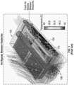
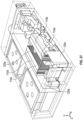
- FIG. 1 is a perspective view of one of many electronic equipment modules that can benefit from the present disclosure.
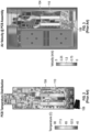
- FIG. 2 is a temperature distribution map of a portion of the module of FIG. 1 .
- FIG. 3 is an air velocity distribution map of the module of FIG. 1 .
- FIG. 4 is a perspective view of one of many examples of an air flow diverter arrangement according to the disclosure.
- FIG. 5 is a cut-away plan view of one of many examples of a system for improved heat dissipation according to the disclosure.
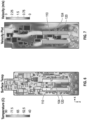
- FIG. 6 is a temperature distribution map of a portion of the system of FIG. 5 .
- FIG. 7 is an air velocity distribution map of the system of FIG. 5 .
- FIG. 8 is a perspective view of one of many examples of an air flow diverter according to the disclosure.
- FIG. 9 is a cut-away perspective view of another one of many examples of a system for improved heat dissipation according to the disclosure.
- FIG. 10 is a cut-away perspective view of the system of FIG. 9 , showing air flow therethrough.
- FIG. 11 is a temperature distribution map of a portion of the system of FIG. 9 .
- FIG. 12 is an air velocity distribution map of a portion of the system of FIG. 9 .
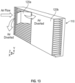
- FIG. 13 is a perspective view of one of many examples of an air flow diverter arrangement according to the disclosure.
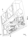
- FIG. 14 is a cut-away perspective view of still another one of many examples of a system for improved heat dissipation according to the disclosure.
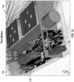
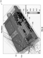
- FIG. 15 is a cut-away perspective view of the system of FIG. 14 , showing air flow therethrough.
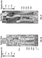
- FIG. 16 is a temperature distribution map of a portion of the system of FIG. 14 .
- FIG. 17 is an air velocity distribution map of a portion of the system of FIG. 14 .
- FIG. 18 is a perspective view of another one of many examples of an air flow diverter arrangement according to the disclosure.
- FIG. 19 is a cut-away plan view of yet another one of many examples of a system for improved heat dissipation according to the disclosure.
- FIG. 20 is a temperature distribution map of a portion of the system of FIG. 19 .
- FIG. 21 is an air velocity distribution map of a portion of the system of FIG. 19 .
- FIG. 22 is a perspective view of another one of many examples of an air flow diverter and heat sink arrangement according to the disclosure.
- FIG. 23 is a cut-away perspective view of another one of many examples of a system for improved heat dissipation according to the disclosure.
- FIG. 24 is a cut-away perspective view of the system of FIG. 23 , showing air flow therethrough.
- FIG. 25 is a temperature distribution map of a portion of the system of FIG. 23 .
- FIG. 26 is an air velocity distribution map of a portion of the system of FIG. 23 .
- FIG. 27 is a cut-away perspective view of yet another one of many examples of a system for improved heat dissipation according to the disclosure.
- FIG. 28 is a perspective view of select components of the system of FIG. 27 .
- FIG. 29 is a cut-away perspective view of the system of FIG. 27 , showing air flow therethrough.
- FIGS. 1-29 are described in conjunction with one another.
- a system according to the disclosure can include one or more electronic equipment housings 102 having one or more heat generating devices 104 therein, one or more fans 106 configured to induce air flow through the housing 102, one or more heat sinks 110 thermally coupled to the heat generating device 104, and one or more diverters 120 positioned to direct at least a portion of the air flow into or towards thermal communication with one or more of the heat sinks 110 or a portion(s) thereof.
- one or more diverters 120 can be advantageously shaped and arranged relative to one or more heat sinks 110 for biasing air flow into channels between fins of a heat sink 110 or otherwise towards heat transfer surfaces of a heat sink 110 for supporting efficient and effective heat transfer or cooling performance.
- the housing 102 can include a rack mounted system, such as for use with rack mounted computer and/or power equipment, such as a server or an uninterruptible power supply (UPS).
- the heat generating device 104 can be a central processing unit (CPU), a graphics processing unit (GPU), an insulated-gate bipolar transistor (IGBT), a field effect transistor (FET), another heat generating device, or any combination thereof.
- one heat sink 110 can be thermally coupled to multiple heat generating devices 104, multiple heat sinks 110 can be thermally coupled to one heat generating device 104, or any combination thereof.
- one heat sink 110 can be thermally coupled to multiple heat generating devices 104, while another heat sink 110 is thermally coupled to some of those heat generating devices 104.
- the diverter 120 can be V-shaped and/or have a V-shaped cross-section. In at least one example, the diverter 120 can present a 120-degree angle. In at least one example, the diverter 120 can present a 90-degree angle. In at least one example, the diverter 120 can present a 60-degree angle. In at least one example, the diverter 120 can present any angle between 0 and 180 degrees. In at least one example, the diverter 120 can be another shape, such as L-shaped, flat, or rounded.
- the diverter 120 can be vertically or horizontally oriented. In at least one example, the diverter 120 can be oriented at an angle with respect to a vertical and/or horizontal axis of the housing 102. In at least one example, the diverter 120 can be thermally conductive and thereby provide some heat sink/dissipation itself. In at least one example, the diverter 120 can be electrically insulative. In at least one example, the diverter 120 can be made of metal or plastic.
- a system 100 for improved heat dissipation can include multiple diverters 120.
- one diverter 120 can direct at least a portion of the air flow into multiple heat sinks 110, multiple diverters 120 can direct at least a portion of the air flow into the same heat sink 110, or any combination thereof.
- one diverter 120 can direct at least a portion of the air flow into multiple heat sinks 110, while another diverter 120 directs at least a portion of the air flow into one or more of those heat sinks 110.
- a system 100 for improved heat dissipation can include a first heat generating device 104a within the housing 102 and a first heat sink 110a thermally coupled to the first heat generating device 104a, a second heat generating device 104b within the housing 102 and a second heat sink 110b thermally coupled to the second heat generating device 104b, a first diverter 120a positioned between the first heat sink 110a and the second heat sink 110b, or any combination thereof.
- the first diverter 120a can direct at least a first portion of the air flow into the first heat sink 110a and at least a second portion of the air flow into the second heat sink 110b.
- a system 100 for improved heat dissipation can include a second and/or third diverter 120b, 120c positioned between the first heat sink 110a and the second heat sink 110b.
- the first diverter 120a can be positioned upstream or downstream, in the air flow, from the second diverter 120b.
- the second diverter 120b can be positioned upstream or downstream, in the air flow, from the third diverter 120c.
- one diverter 120 can be positioned adjacent to (and/or at essentially the same position in the air flow as) another diverter 120.
- the second diverter 120b can be longer or shorter than the first diverter 120a.
- the third diverter 120c can be longer or shorter than the second diverter 120b.
- one diverter 120 can be essentially the same length as another diverter 120.
- one diverter 120 can be positioned at an angle with respect to another diverter 120.
- one diverter 120 can be different than another diverter 120.
- one diverter 120 can be configured to channel air into a heat sink 110, and another diverter can be configured to retain air within that, or another, heat sink 110.
- the second diverter 120b can be configured to direct the first portion of the air flow along the first heat sink 110a.
- the third diverter 120c can be configured to direct the second portion of the air flow along the second heat sink 110b.
- the second diverter 120b can be configured to direct at least a third portion of the air flow into the first heat sink 110a and direct at least a fourth portion of the air flow into the second heat sink 110b.
- downstream of the first diverter 120 the air flow that was diverted into the first and/or second heat sinks 110a, 110b may begin to escape those heat sinks 110a, 110b.
- a second diverter 120b positioned downstream from the first diverter 120 can redivert all or a portion of the air flow that was diverted into the first and/or second heat sinks 110a, 110b by the first diverter 120a.
- a second diverter 120b positioned downstream from the first diverter 120 can divert even more of the air flow that was diverted into the first and/or second heat sinks 110a, 110b by the first diverter 120a.
- a system 100 for improved heat dissipation can include a first heat sink 110a and a second heat sink 110b thermally coupled to the first heat generating device 104a.
- a system 100 for improved heat dissipation can include a second heat generating device 104b within the housing 102, with a third heat sink 110c thermally coupled to the second heat generating device 104b and/or a fourth heat sink 110d thermally coupled to the second heat generating device 104b.
- a first diverter 120a can be configured to direct at least a first portion of the air flow into the first heat sink 110a and/or direct at least a second portion of the air flow into the third heat sink 110c.
- a system 100 for improved heat dissipation can include a second diverter 120b positioned between the first heat sink 110a and the third heat sink 110c.
- a system 100 for improved heat dissipation can include a third diverter 120c configured to direct at least a third portion of the air flow into the second heat sink 110b and/or the first heat sink 110a.
- a system 100 for improved heat dissipation can include a fourth diverter 120d configured to direct at least a fourth portion of the air flow into the fourth heat sink 110d and/or the third heat sink 110c.
- a system 100 for improved heat dissipation can include a fifth diverter 120e configured to retain the first portion of the air flow within the first heat sink 110a.
- a system 100 for improved heat dissipation can include a sixth diverter 120f configured to retain the second portion of the air flow within the third heat sink 110c.
- a system 100 for improved heat dissipation can include any one or more, including all, of the heat sinks 110 and/or diverters 120 described herein.
- a diverter 120 can be or include one or more plates for supporting the diversion or channeling of air into or through one or more heat sinks 110 or portions thereof.
- diverter 120d can be one or more plates for channeling air into both the fourth heat sink 110d and the third heat sink 110c.
- diverter 120e can be one or more plates for retaining, or rediverting, air into heat sink 110a.
- diverter 120a and/or diverter 120b can be one or more plates for channeling air into both the first heat sink 110a and the third heat sink 110c.
- a system for improved heat dissipation can include an electronic equipment housing having a heat generating device therein, a fan configured to induce air flow through the housing, a heat sink thermally coupled to the heat generating device, and a diverter positioned to direct at least a portion of the air flow into the heat sink.
- the diverter can be V-shaped and/or have a V-shaped cross-section.
- the diverter can be vertically or horizontally oriented.
- the diverter can be oriented at an angle with respect to a vertical and/or horizontal axis of the housing.
- a system for improved heat dissipation can include a second heat generating device within the housing and a second heat sink thermally coupled to the second heat generating device.
- the diverter can also direct at least a second portion of the air flow into the second heat sink.
- a system for improved heat dissipation can include a second and/or third diverter positioned between the first heat sink and the second heat sink.
- the first diverter can be positioned upstream, in the air flow, from the second diverter.
- the second diverter can be positioned upstream, in the air flow, from the third diverter.
- the second diverter can be longer than the first diverter.
- the third diverter can be longer than the second diverter.
- the second diverter can be configured to direct at least a third portion of the air flow into the first heat sink and direct at least a fourth portion of the air flow into the second heat sink. In at least one example, the second diverter can be configured to direct the first portion of the air flow along the first heat sink. In at least one example, the third diverter can be configured to direct the second portion of the air flow along the second heat sink.
- a system for improved heat dissipation can include a second heat sink thermally coupled to the first heat generating device.
- a system for improved heat dissipation can include a second heat generating device within the housing, with a third heat sink thermally coupled to the second heat generating device and/or a fourth heat sink thermally coupled to the second heat generating device.
- the first diverter can be configured to also direct at least a second portion of the air flow into the third heat sink.
- a system for improved heat dissipation can include a second diverter positioned between the first heat sink and the third heat sink. In at least one example, a system for improved heat dissipation can include a third diverter configured to direct at least a third portion of the air flow into the second heat sink. In at least one example, a system for improved heat dissipation can include a fourth diverter configured to direct at least a fourth portion of the air flow into the fourth heat sink.
Landscapes
- Engineering & Computer Science (AREA)
- Microelectronics & Electronic Packaging (AREA)
- Physics & Mathematics (AREA)
- Thermal Sciences (AREA)
- Computer Hardware Design (AREA)
- General Engineering & Computer Science (AREA)
- Cooling Or The Like Of Electrical Apparatus (AREA)
Abstract
A system for heat dissipation in an electronic equipment housing having a heat generating device therein can include a fan configured to induce air flow through the housing, a heat sink thermally coupled to the heat generating device, and a diverter positioned to direct at least a portion of the air flow into the heat sink.
Description
- This application claims the benefit of
Indian Provisional Patent Application No. 202321033033 filed May 10, 2023 - Field of the Invention. The present disclosure relates generally to electronic equipment cabinets and more specifically relates to heat dissipation in electronic equipment cabinets.
- Description of the Related Art. Typical electronic equipment includes internal components that generate significant heat, and therefore have fans to draw cooling air through their housings. For example, typical rack mounted computer equipment includes central processing units (CPUs) and/or graphics processing units (GPUs). Particularly hot, and/or heat sensitive, devices may have heat sinks to better dissipate heat. However, cooling air may only thermally couple with a portion of these heat sinks and/or a portion of the cooling air may disperse or otherwise traverse the housing without thermally coupling with a heat sink, thereby leading to inefficiencies.
- Applicants have created new and useful devices, systems and methods for improving heat dissipation. In at least one example, a system for improved heat dissipation can include an electronic equipment housing having a heat generating device therein, a fan configured to induce air flow through the housing, a heat sink thermally coupled to the heat generating device, and a diverter positioned to direct at least a portion of the air flow into the heat sink. In at least one example, the diverter can be V-shaped and/or have a V-shaped cross-section. In at least one example, the diverter can be vertically or horizontally oriented. In at least one example, the diverter can be oriented at an angle with respect to a vertical and/or horizontal axis of the housing.
- In at least one example, a system for improved heat dissipation can include a second heat generating device within the housing and a second heat sink thermally coupled to the second heat generating device. In at least one example, the diverter can also direct at least a second portion of the air flow into the second heat sink.
- In at least one example, a system for improved heat dissipation can include a second and/or third diverter positioned between the first heat sink and the second heat sink. In at least one example, the first diverter can be positioned upstream, in the air flow, from the second diverter. In at least one example, the second diverter can be positioned upstream, in the air flow, from the third diverter. In at least one example, the second diverter can be longer than the first diverter. In at least one example, the third diverter can be longer than the second diverter.
- In at least one example, the second diverter can be configured to direct at least a third portion of the air flow into the first heat sink and direct at least a fourth portion of the air flow into the second heat sink. In at least one example, the second diverter can be configured to direct the first portion of the air flow along the first heat sink. In at least one example, the third diverter can be configured to direct the second portion of the air flow along the second heat sink.
- In at least one example, a system for improved heat dissipation can include a second heat sink thermally coupled to the first heat generating device. In at least one example, a system for improved heat dissipation can include a second heat generating device within the housing, with a third heat sink thermally coupled to the second heat generating device and/or a fourth heat sink thermally coupled to the second heat generating device. In at least one example, the first diverter can be configured to also direct at least a second portion of the air flow into the third heat sink.
- In at least one example, a system for improved heat dissipation can include a second diverter positioned between the first heat sink and the third heat sink. In at least one example, a system for improved heat dissipation can include a third diverter configured to direct at least a third portion of the air flow into the second heat sink. In at least one example, a system for improved heat dissipation can include a fourth diverter configured to direct at least a fourth portion of the air flow into the fourth heat sink.
-
-
FIG. 1 is a perspective view of one of many electronic equipment modules that can benefit from the present disclosure. -
FIG. 2 is a temperature distribution map of a portion of the module ofFIG. 1 . -
FIG. 3 is an air velocity distribution map of the module ofFIG. 1 . -
FIG. 4 is a perspective view of one of many examples of an air flow diverter arrangement according to the disclosure. -
FIG. 5 is a cut-away plan view of one of many examples of a system for improved heat dissipation according to the disclosure. -
FIG. 6 is a temperature distribution map of a portion of the system ofFIG. 5 . -
FIG. 7 is an air velocity distribution map of the system ofFIG. 5 . -
FIG. 8 is a perspective view of one of many examples of an air flow diverter according to the disclosure. -
FIG. 9 is a cut-away perspective view of another one of many examples of a system for improved heat dissipation according to the disclosure. -
FIG. 10 is a cut-away perspective view of the system ofFIG. 9 , showing air flow therethrough. -
FIG. 11 is a temperature distribution map of a portion of the system ofFIG. 9 . -
FIG. 12 is an air velocity distribution map of a portion of the system ofFIG. 9 . -
FIG. 13 is a perspective view of one of many examples of an air flow diverter arrangement according to the disclosure. -
FIG. 14 is a cut-away perspective view of still another one of many examples of a system for improved heat dissipation according to the disclosure. -
FIG. 15 is a cut-away perspective view of the system ofFIG. 14 , showing air flow therethrough. -
FIG. 16 is a temperature distribution map of a portion of the system ofFIG. 14 . -
FIG. 17 is an air velocity distribution map of a portion of the system ofFIG. 14 . -
FIG. 18 is a perspective view of another one of many examples of an air flow diverter arrangement according to the disclosure. -
FIG. 19 is a cut-away plan view of yet another one of many examples of a system for improved heat dissipation according to the disclosure. -
FIG. 20 is a temperature distribution map of a portion of the system ofFIG. 19 . -
FIG. 21 is an air velocity distribution map of a portion of the system ofFIG. 19 . -
FIG. 22 is a perspective view of another one of many examples of an air flow diverter and heat sink arrangement according to the disclosure. -
FIG. 23 is a cut-away perspective view of another one of many examples of a system for improved heat dissipation according to the disclosure. -
FIG. 24 is a cut-away perspective view of the system ofFIG. 23 , showing air flow therethrough. -
FIG. 25 is a temperature distribution map of a portion of the system ofFIG. 23 . -
FIG. 26 is an air velocity distribution map of a portion of the system ofFIG. 23 . -
FIG. 27 is a cut-away perspective view of yet another one of many examples of a system for improved heat dissipation according to the disclosure. -
FIG. 28 is a perspective view of select components of the system ofFIG. 27 . -
FIG. 29 is a cut-away perspective view of the system ofFIG. 27 , showing air flow therethrough. - The figures described above and the written description of specific structures and functions below are not presented to limit the scope of what Applicants have invented or the scope of the appended claims. Rather, the figures and written description are provided to teach any person skilled in the art to make and use the inventions for which patent protection is sought. Those skilled in the art will appreciate that not all features of a commercial example of the inventions are described or shown for the sake of clarity and understanding. Persons of skill in this art will also appreciate that the development of an actual commercial example incorporating aspects of the present inventions will require numerous implementation-specific decisions to achieve the developer's ultimate goal for the commercial example. Such implementation-specific decisions may include, and likely are not limited to, compliance with system-related, business-related, government-related and other constraints, which may vary by specific implementation, location and from time to time. While a developer's efforts might be complex and time-consuming in an absolute sense, such efforts would be, nevertheless, a routine undertaking for those of skill in this art having benefit of this disclosure. It must be understood that the inventions disclosed and taught herein are susceptible to numerous and various modifications and alternative forms.
- The use of a singular term, such as, but not limited to, "a," is not intended as limiting of the number of items. Also, the use of relational terms, such as, but not limited to, "top," "bottom," "left," "right," "upper," "lower," "down," "up," "side," and the like are used in the written description for clarity in specific reference to the figures. The terms "including" and "such as" are illustrative and not limitative. The terms "couple," "coupled," "coupling," "coupler," and like terms are used broadly herein and can include any method or device for securing, binding, bonding, fastening, attaching, joining, inserting therein, forming thereon or therein, communicating, or otherwise associating, for example, mechanically, magnetically, electrically, chemically, operably, directly or indirectly with intermediate elements, one or more pieces of members together and can further include without limitation integrally forming one functional member with another in a unity fashion. The coupling can occur in any direction, including rotationally. Further, all parts and components of the disclosure that are capable of being physically embodied inherently include imaginary and real characteristics regardless of whether such characteristics are expressly described herein, including but not limited to characteristics such as axes, ends, inner and outer surfaces, interior spaces, tops, bottoms, sides, boundaries, dimensions (e.g., height, length, width, thickness), mass, weight, volume and density, among others.
- Any process flowcharts discussed herein illustrate the operation of possible implementations of systems, methods, and computer program products according to various examples of the present disclosure. In this regard, each block in a flowchart may represent a module, segment, or portion of code, which can comprise one or more executable instructions for implementing the specified logical function(s). It should also be noted that, in some implementations, the function(s) noted in the block(s) might occur out of the order depicted in the figures. For example, blocks shown in succession may, in fact, be executed substantially concurrently. It will also be noted that each block of flowchart illustration can be implemented by special purpose hardware-based systems that perform the specified functions or acts, or combinations of special purpose hardware and computer instructions.
- Applicants have created new and useful devices, systems and methods for improving heat dissipation. In at least one example, a system for improved heat dissipation can include an electronic equipment housing having one or more heat generating device(s) therein, at least one fan configured to induce airflow through the housing, one or more heat sink(s) thermally coupled to the heat generating device(s), and at least one diverter positioned to direct at least a portion of the air flow into or otherwise relative to the heat sink(s) for supporting efficient and effective heat transfer.
-
FIG. 1 is a perspective view of one of many electronic equipment modules that can benefit from the present disclosure.FIG. 2 is a temperature distribution map of a portion of the module ofFIG. 1 .FIG. 3 is an air velocity distribution map of the module ofFIG. 1 .FIG. 4 is a perspective view of one of many examples of an air flow diverter arrangement according to the disclosure.FIG. 5 is a cut-away plan view of one of many examples of a system for improved heat dissipation according to the disclosure.FIG. 6 is a temperature distribution map of a portion of the system ofFIG. 5 .FIG. 7 is an air velocity distribution map of the system ofFIG. 5 .FIG. 8 is a perspective view of one of many examples of an air flow diverter according to the disclosure.FIG. 9 is a cut-away perspective view of another one of many examples of a system for improved heat dissipation according to the disclosure.FIG. 10 is a cut-away perspective view of the system ofFIG. 9 , showing air flow therethrough.FIG. 11 is a temperature distribution map of a portion of the system ofFIG. 9 .FIG. 12 is an air velocity distribution map of a portion of the system ofFIG. 9 .FIG. 13 is a perspective view of one of many examples of an air flow diverter arrangement according to the disclosure.FIG. 14 is a cut-away perspective view of still another one of many examples of a system for improved heat dissipation according to the disclosure.FIG. 15 is a cut-away perspective view of the system ofFIG. 14 , showing air flow therethrough.FIG. 16 is a temperature distribution map of a portion of the system ofFIG. 14 .FIG. 17 is an air velocity distribution map of a portion of the system ofFIG. 14 .FIG. 18 is a perspective view of another one of many examples of an air flow diverter arrangement according to the disclosure.FIG. 19 is a cut-away plan view of yet another one of many examples of a system for improved heat dissipation according to the disclosure.FIG. 20 is a temperature distribution map of a portion of the system ofFIG. 19 .FIG. 21 is an air velocity distribution map of a portion of the system ofFIG. 19 .FIG. 22 is a perspective view of another one of many examples of an air flow diverter and heat sink arrangement according to the disclosure.FIG. 23 is a cut-away perspective view of another one of many examples of a system for improved heat dissipation according to the disclosure.FIG. 24 is a cut-away perspective view of the system ofFIG. 23 , showing air flow therethrough.FIG. 25 is a temperature distribution map of a portion of the system ofFIG. 23 .FIG. 26 is an air velocity distribution map of a portion of the system ofFIG. 23 .FIG. 27 is a cut-away perspective view of yet another one of many examples of a system for improved heat dissipation according to the disclosure.FIG. 28 is a perspective view of select components of the system ofFIG. 27 .FIG. 29 is a cut-away perspective view of the system ofFIG. 27 , showing air flow therethrough.FIGS. 1-29 are described in conjunction with one another. - In at least one example, a system according to the disclosure, such as a
system 100 for improved heat dissipation, can include one or moreelectronic equipment housings 102 having one or moreheat generating devices 104 therein, one ormore fans 106 configured to induce air flow through thehousing 102, one ormore heat sinks 110 thermally coupled to theheat generating device 104, and one ormore diverters 120 positioned to direct at least a portion of the air flow into or towards thermal communication with one or more of theheat sinks 110 or a portion(s) thereof. For example, one ormore diverters 120 can be advantageously shaped and arranged relative to one ormore heat sinks 110 for biasing air flow into channels between fins of aheat sink 110 or otherwise towards heat transfer surfaces of aheat sink 110 for supporting efficient and effective heat transfer or cooling performance. In at least one example, thehousing 102 can include a rack mounted system, such as for use with rack mounted computer and/or power equipment, such as a server or an uninterruptible power supply (UPS). In at least one example, theheat generating device 104 can be a central processing unit (CPU), a graphics processing unit (GPU), an insulated-gate bipolar transistor (IGBT), a field effect transistor (FET), another heat generating device, or any combination thereof. In at least one example, oneheat sink 110 can be thermally coupled to multipleheat generating devices 104,multiple heat sinks 110 can be thermally coupled to oneheat generating device 104, or any combination thereof. For example, oneheat sink 110 can be thermally coupled to multipleheat generating devices 104, while anotherheat sink 110 is thermally coupled to some of thoseheat generating devices 104. - In at least one example, the
diverter 120 can be V-shaped and/or have a V-shaped cross-section. In at least one example, thediverter 120 can present a 120-degree angle. In at least one example, thediverter 120 can present a 90-degree angle. In at least one example, thediverter 120 can present a 60-degree angle. In at least one example, thediverter 120 can present any angle between 0 and 180 degrees. In at least one example, thediverter 120 can be another shape, such as L-shaped, flat, or rounded. - In at least one example, the
diverter 120 can be vertically or horizontally oriented. In at least one example, thediverter 120 can be oriented at an angle with respect to a vertical and/or horizontal axis of thehousing 102. In at least one example, thediverter 120 can be thermally conductive and thereby provide some heat sink/dissipation itself. In at least one example, thediverter 120 can be electrically insulative. In at least one example, thediverter 120 can be made of metal or plastic. - In at least one example, a
system 100 for improved heat dissipation can includemultiple diverters 120. In at least one example, onediverter 120 can direct at least a portion of the air flow intomultiple heat sinks 110,multiple diverters 120 can direct at least a portion of the air flow into thesame heat sink 110, or any combination thereof. For example, onediverter 120 can direct at least a portion of the air flow intomultiple heat sinks 110, while anotherdiverter 120 directs at least a portion of the air flow into one or more of those heat sinks 110. - In at least one example, a
system 100 for improved heat dissipation can include a firstheat generating device 104a within thehousing 102 and afirst heat sink 110a thermally coupled to the firstheat generating device 104a, a secondheat generating device 104b within thehousing 102 and asecond heat sink 110b thermally coupled to the secondheat generating device 104b, afirst diverter 120a positioned between thefirst heat sink 110a and thesecond heat sink 110b, or any combination thereof. In at least one example, thefirst diverter 120a can direct at least a first portion of the air flow into thefirst heat sink 110a and at least a second portion of the air flow into thesecond heat sink 110b. - In at least one example, a
system 100 for improved heat dissipation can include a second and/orthird diverter first heat sink 110a and thesecond heat sink 110b. In at least one example, thefirst diverter 120a can be positioned upstream or downstream, in the air flow, from thesecond diverter 120b. In at least one example, thesecond diverter 120b can be positioned upstream or downstream, in the air flow, from thethird diverter 120c. In at least one example, onediverter 120 can be positioned adjacent to (and/or at essentially the same position in the air flow as) anotherdiverter 120. - In at least one example, the
second diverter 120b can be longer or shorter than thefirst diverter 120a. In at least one example, thethird diverter 120c can be longer or shorter than thesecond diverter 120b. In at least one example, onediverter 120 can be essentially the same length as anotherdiverter 120. In at least one example, onediverter 120 can be positioned at an angle with respect to anotherdiverter 120. In at least one example, onediverter 120 can be different than anotherdiverter 120. For example, onediverter 120 can be configured to channel air into aheat sink 110, and another diverter can be configured to retain air within that, or another,heat sink 110. In at least one example, thesecond diverter 120b can be configured to direct the first portion of the air flow along thefirst heat sink 110a. In at least one example, thethird diverter 120c can be configured to direct the second portion of the air flow along thesecond heat sink 110b. - In at least one example, the
second diverter 120b can be configured to direct at least a third portion of the air flow into thefirst heat sink 110a and direct at least a fourth portion of the air flow into thesecond heat sink 110b. For example, downstream of thefirst diverter 120 the air flow that was diverted into the first and/orsecond heat sinks heat sinks second diverter 120b positioned downstream from thefirst diverter 120 can redivert all or a portion of the air flow that was diverted into the first and/orsecond heat sinks first diverter 120a. In at least one example, asecond diverter 120b positioned downstream from thefirst diverter 120 can divert even more of the air flow that was diverted into the first and/orsecond heat sinks first diverter 120a. - In at least one example, a
system 100 for improved heat dissipation can include afirst heat sink 110a and asecond heat sink 110b thermally coupled to the firstheat generating device 104a. In at least one example, asystem 100 for improved heat dissipation can include a secondheat generating device 104b within thehousing 102, with athird heat sink 110c thermally coupled to the secondheat generating device 104b and/or afourth heat sink 110d thermally coupled to the secondheat generating device 104b. In at least one example, afirst diverter 120a can be configured to direct at least a first portion of the air flow into thefirst heat sink 110a and/or direct at least a second portion of the air flow into thethird heat sink 110c. - In at least one example, a
system 100 for improved heat dissipation can include asecond diverter 120b positioned between thefirst heat sink 110a and thethird heat sink 110c. In at least one example, asystem 100 for improved heat dissipation can include athird diverter 120c configured to direct at least a third portion of the air flow into thesecond heat sink 110b and/or thefirst heat sink 110a. In at least one example, asystem 100 for improved heat dissipation can include afourth diverter 120d configured to direct at least a fourth portion of the air flow into thefourth heat sink 110d and/or thethird heat sink 110c. In at least one example, asystem 100 for improved heat dissipation can include afifth diverter 120e configured to retain the first portion of the air flow within thefirst heat sink 110a. In at least one example, asystem 100 for improved heat dissipation can include asixth diverter 120f configured to retain the second portion of the air flow within thethird heat sink 110c. In at least one example, asystem 100 for improved heat dissipation can include any one or more, including all, of theheat sinks 110 and/ordiverters 120 described herein. - In at least one example, a
diverter 120 can be or include one or more plates for supporting the diversion or channeling of air into or through one ormore heat sinks 110 or portions thereof. As shown inFIGS. 28 and29 , for example,diverter 120d can be one or more plates for channeling air into both thefourth heat sink 110d and thethird heat sink 110c. As shown inFIGS. 25 and 26 , for example, diverter 120e can be one or more plates for retaining, or rediverting, air intoheat sink 110a. As also shown inFIGS. 25 and 26 , for example, diverter 120a and/ordiverter 120b can be one or more plates for channeling air into both thefirst heat sink 110a and thethird heat sink 110c. - In at least one example, a system for improved heat dissipation can include an electronic equipment housing having a heat generating device therein, a fan configured to induce air flow through the housing, a heat sink thermally coupled to the heat generating device, and a diverter positioned to direct at least a portion of the air flow into the heat sink. In at least one example, the diverter can be V-shaped and/or have a V-shaped cross-section. In at least one example, the diverter can be vertically or horizontally oriented. In at least one example, the diverter can be oriented at an angle with respect to a vertical and/or horizontal axis of the housing.
- In at least one example, a system for improved heat dissipation can include a second heat generating device within the housing and a second heat sink thermally coupled to the second heat generating device. In at least one example, the diverter can also direct at least a second portion of the air flow into the second heat sink.
- In at least one example, a system for improved heat dissipation can include a second and/or third diverter positioned between the first heat sink and the second heat sink. In at least one example, the first diverter can be positioned upstream, in the air flow, from the second diverter. In at least one example, the second diverter can be positioned upstream, in the air flow, from the third diverter. In at least one example, the second diverter can be longer than the first diverter. In at least one example, the third diverter can be longer than the second diverter.
- In at least one example, the second diverter can be configured to direct at least a third portion of the air flow into the first heat sink and direct at least a fourth portion of the air flow into the second heat sink. In at least one example, the second diverter can be configured to direct the first portion of the air flow along the first heat sink. In at least one example, the third diverter can be configured to direct the second portion of the air flow along the second heat sink.
- In at least one example, a system for improved heat dissipation can include a second heat sink thermally coupled to the first heat generating device. In at least one example, a system for improved heat dissipation can include a second heat generating device within the housing, with a third heat sink thermally coupled to the second heat generating device and/or a fourth heat sink thermally coupled to the second heat generating device. In at least one example, the first diverter can be configured to also direct at least a second portion of the air flow into the third heat sink.
- In at least one example, a system for improved heat dissipation can include a second diverter positioned between the first heat sink and the third heat sink. In at least one example, a system for improved heat dissipation can include a third diverter configured to direct at least a third portion of the air flow into the second heat sink. In at least one example, a system for improved heat dissipation can include a fourth diverter configured to direct at least a fourth portion of the air flow into the fourth heat sink.
- Other and further examples utilizing one or more aspects of the disclosure can be devised without departing from the spirit of Applicants' disclosure. For example, the devices, systems and methods can be implemented for numerous different types and sizes in numerous different industries. Further, the various methods and examples of the devices, systems and methods can be included in combination with each other to produce variations of the disclosed methods and examples. Discussion of singular elements can include plural elements and vice versa. The order of steps can occur in a variety of sequences unless otherwise specifically limited. The various steps described herein can be combined with other steps, interlineated with the stated steps, and/or split into multiple steps. Similarly, elements have been described functionally and can be embodied as separate components or can be combined into components having multiple functions.
- Further examples are set out in the clauses below:
- 1. A system comprising: an electronic equipment housing having a first heat generating device therein; a fan configured to induce air flow through the housing; a first heat sink thermally coupled to the first heat generating device; and a first diverter positioned to direct at least a first portion of the air flow into the first heat sink.
- 2. The system of clause 1, further comprising a second heat generating device within the housing and a second heat sink thermally coupled to the second heat generating device, and wherein the first diverter is configured to also direct at least a second portion of the air flow into the second heat sink.
- 3. The system of clause 1 or 2, wherein the first diverter is V-shaped.
- 4. The system of any one of clauses 1-3, wherein the first diverter has a V-shaped cross-section.
- 5. The system of clause any one of clauses 1-4, wherein the first diverter is vertically oriented.
- 6. The system of any one of clauses 1-5, wherein the first diverter is oriented at a first angle with respect to a vertical axis.
- 7. The system of any one of clauses 1-4, wherein the first diverter is horizontally oriented.
- 8. The system of any one of clauses 1-7, wherein the first diverter is oriented at a first angle with respect to a horizontal axis.
- 9. The system of any one of clauses 2-8, further comprising a second diverter positioned between the first heat sink and the second heat sink.
- 10. The system of clause 9, wherein the first diverter is positioned upstream, in the air flow, from the second diverter.
- 11. The system of clause 9 or 10, wherein the second diverter is configured to direct at least a third portion of the air flow into the first heat sink and to direct at least a fourth portion of the air flow into the second heat sink.
- 12. The system of any one of clauses 9-11, further comprising a third diverter positioned between the first heat sink and the second heat sink, wherein the second diverter is configured to direct the first portion of the air flow along the first heat sink and the third diverter is configured to direct the second portion of the air flow along the second heat sink.
- 13. The system of any one of clauses 9-12, wherein the second diverter is longer than the first diverter.
- 14. The system of clause 1, further comprising a second heat sink thermally coupled to the first heat generating device.
- 15. The system of clause 14, further comprising a second heat generating device within the housing, a third heat sink thermally coupled to the second heat generating device, and a fourth heat sink thermally coupled to the second heat generating device.
- 16. The system of clause 14 or 15, wherein the first diverter is configured to also direct at least a second portion of the air flow into the third heat sink.
- 17. The system of any one of clauses 14 -16, further comprising a second diverter configured to direct at least a third portion of the air flow into the second heat sink.
- 18. The system of any one of clauses 15 or 17, further comprising a third diverter configured to direct at least a fourth portion of the air flow into the fourth heat sink.
- 19. The system of clause 16, further comprising a second diverter positioned between the first heat sink and the third heat sink.
- 20. The system of clause 18 or 19, further comprising a fourth diverter positioned between the first heat sink and the third heat sink.
- Obvious modifications and alterations to the described examples are available to those of ordinary skill in the art having the benefits of the present disclosure. The disclosed and undisclosed examples are not intended to limit or restrict the scope or applicability of the inventions conceived of by the Applicants, but rather, in conformity with the patent laws, Applicants intend to fully protect all such modifications and improvements that come within the scope or range of equivalents of the following claims.
Claims (15)
- A system comprising:an electronic equipment housing having a first heat generating device therein;a fan configured to induce air flow through the housing;a first heat sink thermally coupled to the first heat generating device; anda first diverter positioned to direct at least a first portion of the air flow into the first heat sink.
- The system of claim 1, further comprising a second heat generating device within the housing and a second heat sink thermally coupled to the second heat generating device, and wherein the first diverter is configured to also direct at least a second portion of the air flow into the second heat sink.
- The system of claim 1 or 2, wherein the first diverter is V-shaped; or optionallywherein the first diverter has a V-shaped cross-section; or optionallywherein the first diverter is vertically oriented.
- The system of any one of claims 1-3, wherein the first diverter is oriented at a first angle with respect to a vertical axis.
- The system of claim 1 or 2, wherein the first diverter is horizontally oriented.
- The system of any one of the preceding claims, wherein the first diverter is oriented at a first angle with respect to a horizontal axis.
- The system of any one of claims 2-6, further comprising a second diverter positioned between the first heat sink and the second heat sink.
- The system of claim 7, wherein the first diverter is positioned upstream, in the air flow, from the second diverter; or optionallywherein the second diverter is configured to direct at least a third portion of the air flow into the first heat sink and to direct at least a fourth portion of the air flow into the second heat sink; or optionallyfurther comprising a third diverter positioned between the first heat sink and the second heat sink, wherein the second diverter is configured to direct the first portion of the air flow along the first heat sink and the third diverter is configured to direct the second portion of the air flow along the second heat sink; or optionallywherein the second diverter is longer than the first diverter.
- The system of claim 1, further comprising a second heat sink thermally coupled to the first heat generating device.
- The system of claim 9, further comprising a second heat generating device within the housing, a third heat sink thermally coupled to the second heat generating device, and a fourth heat sink thermally coupled to the second heat generating device.
- The system of claim 10, wherein the first diverter is configured to also direct at least a second portion of the air flow into the third heat sink.
- The system of any one of claims 10-11, further comprising a second diverter configured to direct at least a third portion of the air flow into the second heat sink.
- The system of any one of claims 10 -12, further comprising a third diverter configured to direct at least a fourth portion of the air flow into the fourth heat sink.
- The system of claim 11, further comprising a second diverter positioned between the first heat sink and the third heat sink.
- The system of any one of claims 10-14, further comprising a fourth diverter positioned between the first heat sink and the third heat sink.
Applications Claiming Priority (1)
| Application Number | Priority Date | Filing Date | Title |
|---|---|---|---|
| IN202321033033 | 2023-05-10 |
Publications (1)
| Publication Number | Publication Date |
|---|---|
| EP4462969A1 true EP4462969A1 (en) | 2024-11-13 |
Family
ID=91070294
Family Applications (1)
| Application Number | Title | Priority Date | Filing Date |
|---|---|---|---|
| EP24175042.1A Pending EP4462969A1 (en) | 2023-05-10 | 2024-05-09 | Systems, devices, and methods for improving heat dissipation |
Country Status (3)
| Country | Link |
|---|---|
| US (1) | US20250351291A1 (en) |
| EP (1) | EP4462969A1 (en) |
| CN (1) | CN118946077A (en) |
Citations (4)
| Publication number | Priority date | Publication date | Assignee | Title |
|---|---|---|---|---|
| US20020071250A1 (en) * | 2000-12-11 | 2002-06-13 | Shoei-Yuan Shih | Fan flow guide |
| US20070235168A1 (en) * | 2006-04-10 | 2007-10-11 | Super Micro Computer, Inc. | Air flow diversion device for dissipating heat from electronic components |
| US20080041562A1 (en) * | 2006-08-18 | 2008-02-21 | Sun Microsystems, Inc. | Airflow bypass and cooling of processors in series |
| US20190053401A1 (en) * | 2016-04-15 | 2019-02-14 | Hewlett Packard Enterprise Development Lp | Extension portion of heatsink above a processing component |
-
2024
- 2024-05-09 EP EP24175042.1A patent/EP4462969A1/en active Pending
- 2024-05-10 CN CN202410577421.4A patent/CN118946077A/en active Pending
- 2024-05-10 US US18/661,559 patent/US20250351291A1/en active Pending
Patent Citations (4)
| Publication number | Priority date | Publication date | Assignee | Title |
|---|---|---|---|---|
| US20020071250A1 (en) * | 2000-12-11 | 2002-06-13 | Shoei-Yuan Shih | Fan flow guide |
| US20070235168A1 (en) * | 2006-04-10 | 2007-10-11 | Super Micro Computer, Inc. | Air flow diversion device for dissipating heat from electronic components |
| US20080041562A1 (en) * | 2006-08-18 | 2008-02-21 | Sun Microsystems, Inc. | Airflow bypass and cooling of processors in series |
| US20190053401A1 (en) * | 2016-04-15 | 2019-02-14 | Hewlett Packard Enterprise Development Lp | Extension portion of heatsink above a processing component |
Also Published As
| Publication number | Publication date |
|---|---|
| CN118946077A (en) | 2024-11-12 |
| US20250351291A1 (en) | 2025-11-13 |
Similar Documents
| Publication | Publication Date | Title |
|---|---|---|
| US11713927B2 (en) | Heat dissipation device | |
| US7345873B2 (en) | System and method for cooling electronic systems | |
| US20060102322A1 (en) | Integrated heat exchangers in a rack for verticle board style computer systems | |
| US9474187B2 (en) | Systems and methods for thermal management for telecommunications enclosures using heat pipes | |
| US20090000768A1 (en) | Heat dissipation device | |
| US12439551B2 (en) | Liquid cooling plate assembly and server | |
| US20040256085A1 (en) | Finned device for removing heat from an electronic component | |
| US7312992B2 (en) | Apparatus and method for transferring heat from processors | |
| US9192077B2 (en) | Baffle for air flow redirection | |
| CN101902895A (en) | cooling system | |
| US10822096B2 (en) | Avionics cooling module | |
| US11672101B2 (en) | Sealed communications module with multi-path thermal management system | |
| CN111107732A (en) | Method and cooling system for maintaining a server rack within a predetermined temperature range | |
| US20110149504A1 (en) | Fan casing integrated heat spreader for active cooling of computing system skins | |
| CN107024967A (en) | Industrial service device and its Multi-path radiating structure | |
| KR101474616B1 (en) | Cooling system of power semiconductor device | |
| EP3273471A1 (en) | Method, system, and electronic assembly for thermal management | |
| US20250351291A1 (en) | Systems, devices, and methods for improving heat dissipation | |
| US10212847B1 (en) | Air guiding duct, casing, and electronic device using the same | |
| US20100139892A1 (en) | Heat dissipation device | |
| US20230200001A1 (en) | Power supply device | |
| US11467638B2 (en) | Water-cooling head adjustment structure for computer water cooling | |
| US11259442B2 (en) | Adjustment structure for computer water cooling | |
| CN102592686A (en) | Heat exchanger | |
| CN2899392Y (en) | Telecommunicating equipment cabinet |
Legal Events
| Date | Code | Title | Description |
|---|---|---|---|
| PUAI | Public reference made under article 153(3) epc to a published international application that has entered the european phase |
Free format text: ORIGINAL CODE: 0009012 |
|
| STAA | Information on the status of an ep patent application or granted ep patent |
Free format text: STATUS: THE APPLICATION HAS BEEN PUBLISHED |
|
| AK | Designated contracting states |
Kind code of ref document: A1 Designated state(s): AL AT BE BG CH CY CZ DE DK EE ES FI FR GB GR HR HU IE IS IT LI LT LU LV MC ME MK MT NL NO PL PT RO RS SE SI SK SM TR |
|
| STAA | Information on the status of an ep patent application or granted ep patent |
Free format text: STATUS: REQUEST FOR EXAMINATION WAS MADE |
|
| 17P | Request for examination filed |
Effective date: 20250506 |