EP4462950A1 - Heating device - Google Patents
Heating device Download PDFInfo
- Publication number
- EP4462950A1 EP4462950A1 EP23172379.2A EP23172379A EP4462950A1 EP 4462950 A1 EP4462950 A1 EP 4462950A1 EP 23172379 A EP23172379 A EP 23172379A EP 4462950 A1 EP4462950 A1 EP 4462950A1
- Authority
- EP
- European Patent Office
- Prior art keywords
- heating
- transistor switch
- heating device
- resistors
- negative terminal
- Prior art date
- Legal status (The legal status is an assumption and is not a legal conclusion. Google has not performed a legal analysis and makes no representation as to the accuracy of the status listed.)
- Granted
Links
Images



Classifications
-
- F—MECHANICAL ENGINEERING; LIGHTING; HEATING; WEAPONS; BLASTING
- F24—HEATING; RANGES; VENTILATING
- F24H—FLUID HEATERS, e.g. WATER OR AIR HEATERS, HAVING HEAT-GENERATING MEANS, e.g. HEAT PUMPS, IN GENERAL
- F24H1/00—Water heaters, e.g. boilers, continuous-flow heaters or water-storage heaters
- F24H1/0072—Special adaptations
- F24H1/009—Special adaptations for vehicle systems
-
- H—ELECTRICITY
- H05—ELECTRIC TECHNIQUES NOT OTHERWISE PROVIDED FOR
- H05B—ELECTRIC HEATING; ELECTRIC LIGHT SOURCES NOT OTHERWISE PROVIDED FOR; CIRCUIT ARRANGEMENTS FOR ELECTRIC LIGHT SOURCES, IN GENERAL
- H05B3/00—Ohmic-resistance heating
- H05B3/02—Details
-
- B—PERFORMING OPERATIONS; TRANSPORTING
- B60—VEHICLES IN GENERAL
- B60H—ARRANGEMENTS OF HEATING, COOLING, VENTILATING OR OTHER AIR-TREATING DEVICES SPECIALLY ADAPTED FOR PASSENGER OR GOODS SPACES OF VEHICLES
- B60H1/00—Heating, cooling or ventilating devices
- B60H1/22—Heating, cooling or ventilating devices the heat source being other than the propulsion plant
- B60H1/2215—Heating, cooling or ventilating devices the heat source being other than the propulsion plant the heat being derived from electric heaters
- B60H1/2221—Heating, cooling or ventilating devices the heat source being other than the propulsion plant the heat being derived from electric heaters arrangements of electric heaters for heating an intermediate liquid
-
- F—MECHANICAL ENGINEERING; LIGHTING; HEATING; WEAPONS; BLASTING
- F24—HEATING; RANGES; VENTILATING
- F24H—FLUID HEATERS, e.g. WATER OR AIR HEATERS, HAVING HEAT-GENERATING MEANS, e.g. HEAT PUMPS, IN GENERAL
- F24H1/00—Water heaters, e.g. boilers, continuous-flow heaters or water-storage heaters
- F24H1/10—Continuous-flow heaters, i.e. heaters in which heat is generated only while the water is flowing, e.g. with direct contact of the water with the heating medium
- F24H1/12—Continuous-flow heaters, i.e. heaters in which heat is generated only while the water is flowing, e.g. with direct contact of the water with the heating medium in which the water is kept separate from the heating medium
- F24H1/121—Continuous-flow heaters, i.e. heaters in which heat is generated only while the water is flowing, e.g. with direct contact of the water with the heating medium in which the water is kept separate from the heating medium using electric energy supply
-
- F—MECHANICAL ENGINEERING; LIGHTING; HEATING; WEAPONS; BLASTING
- F24—HEATING; RANGES; VENTILATING
- F24H—FLUID HEATERS, e.g. WATER OR AIR HEATERS, HAVING HEAT-GENERATING MEANS, e.g. HEAT PUMPS, IN GENERAL
- F24H9/00—Details
- F24H9/18—Arrangement or mounting of grates or heating means
- F24H9/1809—Arrangement or mounting of grates or heating means for water heaters
- F24H9/1818—Arrangement or mounting of electric heating means
-
- H—ELECTRICITY
- H05—ELECTRIC TECHNIQUES NOT OTHERWISE PROVIDED FOR
- H05B—ELECTRIC HEATING; ELECTRIC LIGHT SOURCES NOT OTHERWISE PROVIDED FOR; CIRCUIT ARRANGEMENTS FOR ELECTRIC LIGHT SOURCES, IN GENERAL
- H05B1/00—Details of electric heating devices
- H05B1/02—Automatic switching arrangements specially adapted to apparatus ; Control of heating devices
- H05B1/0202—Switches
-
- H—ELECTRICITY
- H05—ELECTRIC TECHNIQUES NOT OTHERWISE PROVIDED FOR
- H05B—ELECTRIC HEATING; ELECTRIC LIGHT SOURCES NOT OTHERWISE PROVIDED FOR; CIRCUIT ARRANGEMENTS FOR ELECTRIC LIGHT SOURCES, IN GENERAL
- H05B1/00—Details of electric heating devices
- H05B1/02—Automatic switching arrangements specially adapted to apparatus ; Control of heating devices
- H05B1/0227—Applications
- H05B1/023—Industrial applications
- H05B1/0236—Industrial applications for vehicles
-
- H—ELECTRICITY
- H05—ELECTRIC TECHNIQUES NOT OTHERWISE PROVIDED FOR
- H05B—ELECTRIC HEATING; ELECTRIC LIGHT SOURCES NOT OTHERWISE PROVIDED FOR; CIRCUIT ARRANGEMENTS FOR ELECTRIC LIGHT SOURCES, IN GENERAL
- H05B3/00—Ohmic-resistance heating
- H05B3/02—Details
- H05B3/03—Electrodes
-
- H—ELECTRICITY
- H05—ELECTRIC TECHNIQUES NOT OTHERWISE PROVIDED FOR
- H05B—ELECTRIC HEATING; ELECTRIC LIGHT SOURCES NOT OTHERWISE PROVIDED FOR; CIRCUIT ARRANGEMENTS FOR ELECTRIC LIGHT SOURCES, IN GENERAL
- H05B3/00—Ohmic-resistance heating
- H05B3/10—Heating elements characterised by the composition or nature of the materials or by the arrangement of the conductor
- H05B3/16—Heating elements characterised by the composition or nature of the materials or by the arrangement of the conductor the conductor being mounted on an insulating base
-
- H—ELECTRICITY
- H05—ELECTRIC TECHNIQUES NOT OTHERWISE PROVIDED FOR
- H05B—ELECTRIC HEATING; ELECTRIC LIGHT SOURCES NOT OTHERWISE PROVIDED FOR; CIRCUIT ARRANGEMENTS FOR ELECTRIC LIGHT SOURCES, IN GENERAL
- H05B3/00—Ohmic-resistance heating
- H05B3/20—Heating elements having extended surface area substantially in a two-dimensional [2D] plane, e.g. plate-heater
-
- H—ELECTRICITY
- H05—ELECTRIC TECHNIQUES NOT OTHERWISE PROVIDED FOR
- H05B—ELECTRIC HEATING; ELECTRIC LIGHT SOURCES NOT OTHERWISE PROVIDED FOR; CIRCUIT ARRANGEMENTS FOR ELECTRIC LIGHT SOURCES, IN GENERAL
- H05B3/00—Ohmic-resistance heating
- H05B3/20—Heating elements having extended surface area substantially in a two-dimensional [2D] plane, e.g. plate-heater
- H05B3/22—Heating elements having extended surface area substantially in a two-dimensional [2D] plane, e.g. plate-heater non-flexible
-
- H—ELECTRICITY
- H05—ELECTRIC TECHNIQUES NOT OTHERWISE PROVIDED FOR
- H05B—ELECTRIC HEATING; ELECTRIC LIGHT SOURCES NOT OTHERWISE PROVIDED FOR; CIRCUIT ARRANGEMENTS FOR ELECTRIC LIGHT SOURCES, IN GENERAL
- H05B3/00—Ohmic-resistance heating
- H05B3/20—Heating elements having extended surface area substantially in a two-dimensional [2D] plane, e.g. plate-heater
- H05B3/22—Heating elements having extended surface area substantially in a two-dimensional [2D] plane, e.g. plate-heater non-flexible
- H05B3/26—Heating elements having extended surface area substantially in a two-dimensional [2D] plane, e.g. plate-heater non-flexible heating conductor mounted on insulating base
- H05B3/262—Heating elements having extended surface area substantially in a two-dimensional [2D] plane, e.g. plate-heater non-flexible heating conductor mounted on insulating base the insulating base being an insulated metal plate
-
- H—ELECTRICITY
- H05—ELECTRIC TECHNIQUES NOT OTHERWISE PROVIDED FOR
- H05B—ELECTRIC HEATING; ELECTRIC LIGHT SOURCES NOT OTHERWISE PROVIDED FOR; CIRCUIT ARRANGEMENTS FOR ELECTRIC LIGHT SOURCES, IN GENERAL
- H05B2203/00—Aspects relating to Ohmic resistive heating covered by group H05B3/00
- H05B2203/002—Heaters using a particular layout for the resistive material or resistive elements
- H05B2203/007—Heaters using a particular layout for the resistive material or resistive elements using multiple electrically connected resistive elements or resistive zones
-
- H—ELECTRICITY
- H05—ELECTRIC TECHNIQUES NOT OTHERWISE PROVIDED FOR
- H05B—ELECTRIC HEATING; ELECTRIC LIGHT SOURCES NOT OTHERWISE PROVIDED FOR; CIRCUIT ARRANGEMENTS FOR ELECTRIC LIGHT SOURCES, IN GENERAL
- H05B2203/00—Aspects relating to Ohmic resistive heating covered by group H05B3/00
- H05B2203/021—Heaters specially adapted for heating liquids
Definitions
- the invention refers to a heating device, especially for an automobile.
- a heating device according to the preamble of claim 1 is known from US 2022/0082297 A1 .
- Heating devices like flow heaters, comprising a heating resistor assembly, e.g. a metallic heating plate with a resistive track, are used in automobiles for heating various fluids, e.g. air, water or aqueous solutions.
- a heating resistor assembly e.g. a metallic heating plate with a resistive track
- various fluids e.g. air, water or aqueous solutions.
- An object of the invention is to show how electromagnetic compatibility of a heating device for high voltage applications can be improved at low cost.
- a heating device comprises a heating resistor assembly which comprises a positive terminal, a negative terminal, and heating resistors connected in series between the positive terminal and the negative terminal.
- electromagnetic emissions are minimized in such a way that a first half of the heating resistors connects a positive terminal of the heating resistor assembly to a transistor switch and a second half of the heating resistors connects the transistor switch to a negative terminal of the heating resistor assembly.
- the heating load is split into a first half and a second half arranged on a high side and a low side of the transistor switch, respectively. Parasitic capacitances of the heating load are thereby separated into parasitic capacitances of the first and the second half of the heating resistors and are thereby balanced.
- the heating resistor assembly is a heating plate comprising a metal sheet, on which the heating resistors are arranged as resistive tracks, and an insulation layer insulating the resistive tracks from the metal sheet.
- a first half of the resistive tracks then connects the positive terminal to the transistor switch and a second half of the resistive tracks connects the transistor switch to the negative terminal.
- Parasitic capacitances of the heating load are thereby separated into parasitic capacitances between the first half of the resistive tracks and the metal plate and parasitic capacitances between the second half of the tracks and the metal plate.
- both halves of the resistive tracks load are physically or geometrically symmetrical. Thereby electrical symmetry can be achieved more easily to a larger extent.
- the heating resistor assembly may be a heating plate with resistive tracks.
- the heating resistor assembly may comprise PTC resistor plates or blocks, e.g. in heating rods of an air heater.
- the heating device shown in Figures 1 and 2 is a flow heater for an automobile.
- the flow heater has a housing 1 with an inlet 2 and an outlet 3 as well as electrical connectors 4, 5 and a heating resistor assembly provided as a heating plate 6.
- a flow channel for liquid to be heated extends in the housing 1 from the inlet 2 to the outlet 3.
- the flow channel runs along a heating plate 6.
- the metal plate 6 may carry a corrugated sheet 7, which protrudes into the flow channel.
- the heating plate 6 shown in fig. 4 comprises heating resistors 10 provided in the as resistive tracks. In operation, heating current flows through these resistive tracks 10 of the heating plate 6.
- control circuitry 8 for controlling heating power by pulse with modulation of heating current.
- the heating resistors 10 of the heating plate 6 may be electrically connected to the control circuitry by means of press-fit contacts that are pressed into openings of a circuit board and soldered to the heating plate 6.
- Fig. 3 shows schematically a circuit diagram of the flow heater that is configured to be operated at high voltage, e.g. voltage in the rage of 100 V to 1 kV.
- the control circuitry comprises a driver 20 that operates a transistor switch 21 for pulse width modulation.
- Switch 21 is a high side switch. While it is closed, a duty cycle of pulse width modulation is applied and heating current flows through a heating resistor provided as a resistive track of the heating plate 6.
- the high side switch 21 splits the resistive tracks and thereby the heating resistors 10 into a first half 10a and a second half 10b.
- the first half 10a of the heating resistors 10 When switch 21 is open, the first half 10a of the heating resistors 10 is on positive potential and the second half of the heating resistors 10 is on negative potential. Both halves 10a, 10b form a capacitance with a metallic substrate 11 of the resistive tracks, e.g. a plate made of steel or aluminum.
- the metallic substrate 11 may be grounded by an electrical connection to mass.
- Parasitic capacitances of the first half 10a of the resistive tracks and parasitic capacitances of the second half 10b of the resistive tracks are therefore charged with opposite polarity. Therefore, any radiated and conducted emissions caused by these parasitic capacitances are canceled to a large extent, especially if the heating plate 6 is designed symmetrically on both side of the transistor switch 21.
- Fig. 4 shows an illustrative embodiment of the heating plate 6.
- the heating plate 6 comprises a metal sheet 11, e.g. a steel or aluminum sheet, as a substrate and heating resistors 10 provided as resistive tracks that are electrically insulated from the metal sheet 11 by means of an insulating layer 12 arranged between the metal sheet 11 and the resistive tracks.
- the resistive tracks might be printed onto the insulating layer 12 or deposited on it by other means, e.g. physical or chemical vapor deposition.
- the heating plate 6 has a positive terminal 13 for connection to positive potential and a negative terminal 14 for connection to negative potential of a high voltage source.
- the positive terminal 13 and the negative terminal 14 are provided as solder pads at the ends of the resistive tracks such that a connection to circuit board 8 may be made by soldering a connector pin to the terminals 13, 14, e.g. as a surface mounted device.
- the transistor switch 21 shown in fig. 3 is electrically connected to solder pads 15, 16, e.g. by means of connector pins soldered to solder pads 15, 16 and may be arranged on printed circuit board 8.
- a first half 10a of the resistive tracks runs from the positive terminal 13 to solder pad 15 and thereby electrically connects the positive terminal 13 to transistor switch 21 of fig. 3 .
- a second half 10b of the resistive tracks runs from solder pad 16 to the negative terminal 14 and thereby electrically connects the transistor switch 21 to the negative terminal 14.
- the heating plate 6 may have a symmetrical design as shown in fig. 4 to have electrical symmetry. Then the parasitic capacitances of the first half 10a and the second half 10b of the resistive tracks are balanced to the largest extent possible and emissions can thus be minimized.
- control circuitry may comprise a safety switch 22, e.g. a low side switch, that is operated by a driver 23, e.g. if overheating is detected.
- a safety switch 22 e.g. a low side switch
Landscapes
- Engineering & Computer Science (AREA)
- Physics & Mathematics (AREA)
- Thermal Sciences (AREA)
- Mechanical Engineering (AREA)
- Chemical & Material Sciences (AREA)
- Combustion & Propulsion (AREA)
- General Engineering & Computer Science (AREA)
- Air-Conditioning For Vehicles (AREA)
Abstract
Description
- The invention refers to a heating device, especially for an automobile. A heating device according to the preamble of
claim 1 is known fromUS 2022/0082297 A1 . - Heating devices, like flow heaters, comprising a heating resistor assembly, e.g. a metallic heating plate with a resistive track, are used in automobiles for heating various fluids, e.g. air, water or aqueous solutions. As the on-board supply voltage of automobiles has been increased to several hundred volts, it is becoming more difficult to meet stringent requirements for electromagnetic compatibility, especially if the heating device is operated with a pulse width modulated voltage.
- An object of the invention is to show how electromagnetic compatibility of a heating device for high voltage applications can be improved at low cost.
- This object is achieved with a heating device according to
claim 1. Advantageous refinements of the invention are the matter of dependent claims. - A heating device according to the present invention comprises a heating resistor assembly which comprises a positive terminal, a negative terminal, and heating resistors connected in series between the positive terminal and the negative terminal.
- According to the present invention, electromagnetic emissions are minimized in such a way that a first half of the heating resistors connects a positive terminal of the heating resistor assembly to a transistor switch and a second half of the heating resistors connects the transistor switch to a negative terminal of the heating resistor assembly. The heating load is split into a first half and a second half arranged on a high side and a low side of the transistor switch, respectively. Parasitic capacitances of the heating load are thereby separated into parasitic capacitances of the first and the second half of the heating resistors and are thereby balanced.
- When the transistor switch is open, parasitic capacitances between the first half of the heating load and the parasitic capacitances of the second half of the heating load are of opposite polarity so they are charged in opposite direction. When the transistor switch closes, the parasitic capacitances are discharged between them. The system is thereby balanced and currents charging and discharging the parasitic capacitances of each half of the heating load cancel each other to a large extent, reducing the common mode current generated by the system, especially if both halves of the heating load are electrically symmetrical. Radiated and conducted emissions are thereby greatly reduced and electromagnetic compatibility improved, which is especially important for heating devices in automobiles.
- In a refinement of the invention, the heating resistor assembly is a heating plate comprising a metal sheet, on which the heating resistors are arranged as resistive tracks, and an insulation layer insulating the resistive tracks from the metal sheet. A first half of the resistive tracks then connects the positive terminal to the transistor switch and a second half of the resistive tracks connects the transistor switch to the negative terminal. Parasitic capacitances of the heating load are thereby separated into parasitic capacitances between the first half of the resistive tracks and the metal plate and parasitic capacitances between the second half of the tracks and the metal plate.
- When the transistor switch is open, the parasitic capacitances between the first half of the tracks and the metal plate and the parasitic capacitances between the second half of the tracks and the metal plate are of opposite polarity so they are charged in opposite direction. When the transistor switch closes, the parasitic capacitances are discharged between them. The system is thereby balanced and the currents both charging and discharging of the parasitic capacitances of each half of the resistive tracks cancel each other to a large extent, reducing the common mode current generated by the system, especially if both halves of the resistive tracks are electrically symmetrical. Radiated and conducted emissions are thereby greatly reduced and electromagnetic compatibility improved. In a refinement of the invention, both halves of the resistive tracks load are physically or geometrically symmetrical. Thereby electrical symmetry can be achieved more easily to a larger extent.
- As described above, the heating resistor assembly may be a heating plate with resistive tracks. In another embodiment of the invention, the heating resistor assembly may comprise PTC resistor plates or blocks, e.g. in heating rods of an air heater.
- The above-mentioned aspects of exemplary embodiments will become more apparent and will be better understood by reference to the following description of an illustrative embodiment of the invention taken in conjunction with the accompanying drawings, wherein:
-
Fig. 1 shows an illustrative embodiment of a flow heater; -
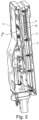
Fig. 2 shows a cross-sectional view offig. 1 ; -
Fig. 3 shows a circuit diagram of the flow heater; and -
Fig. 4 shows an example of a heating plate of the flow heater. - The heating device shown in
Figures 1 and2 is a flow heater for an automobile. The flow heater has ahousing 1 with aninlet 2 and anoutlet 3 as well aselectrical connectors 4, 5 and a heating resistor assembly provided as aheating plate 6. A flow channel for liquid to be heated extends in thehousing 1 from theinlet 2 to theoutlet 3. - The flow channel runs along a
heating plate 6. In order to improve heat dissipation to the liquid in the flow channel, themetal plate 6 may carry acorrugated sheet 7, which protrudes into the flow channel. On its dry side theheating plate 6 shown infig. 4 comprisesheating resistors 10 provided in the as resistive tracks. In operation, heating current flows through theseresistive tracks 10 of theheating plate 6. In a dry compartment of thehousing 1 iscontrol circuitry 8 for controlling heating power by pulse with modulation of heating current. - The
heating resistors 10 of theheating plate 6 may be electrically connected to the control circuitry by means of press-fit contacts that are pressed into openings of a circuit board and soldered to theheating plate 6. -
Fig. 3 shows schematically a circuit diagram of the flow heater that is configured to be operated at high voltage, e.g. voltage in the rage of 100 V to 1 kV. The control circuitry comprises adriver 20 that operates a transistor switch 21 for pulse width modulation. Switch 21 is a high side switch. While it is closed, a duty cycle of pulse width modulation is applied and heating current flows through a heating resistor provided as a resistive track of theheating plate 6. As can be seen infig. 3 , the high side switch 21 splits the resistive tracks and thereby theheating resistors 10 into a first half 10a and a second half 10b. When switch 21 is open, the first half 10a of theheating resistors 10 is on positive potential and the second half of theheating resistors 10 is on negative potential. Both halves 10a, 10b form a capacitance with ametallic substrate 11 of the resistive tracks, e.g. a plate made of steel or aluminum. Themetallic substrate 11 may be grounded by an electrical connection to mass. - Parasitic capacitances of the first half 10a of the resistive tracks and parasitic capacitances of the second half 10b of the resistive tracks are therefore charged with opposite polarity. Therefore, any radiated and conducted emissions caused by these parasitic capacitances are canceled to a large extent, especially if the
heating plate 6 is designed symmetrically on both side of the transistor switch 21. -
Fig. 4 shows an illustrative embodiment of theheating plate 6. Theheating plate 6 comprises ametal sheet 11, e.g. a steel or aluminum sheet, as a substrate andheating resistors 10 provided as resistive tracks that are electrically insulated from themetal sheet 11 by means of aninsulating layer 12 arranged between themetal sheet 11 and the resistive tracks. The resistive tracks might be printed onto theinsulating layer 12 or deposited on it by other means, e.g. physical or chemical vapor deposition. - The
heating plate 6 has a positive terminal 13 for connection to positive potential and anegative terminal 14 for connection to negative potential of a high voltage source. The positive terminal 13 and thenegative terminal 14 are provided as solder pads at the ends of the resistive tracks such that a connection tocircuit board 8 may be made by soldering a connector pin to theterminals 13, 14, e.g. as a surface mounted device. - The transistor switch 21 shown in
fig. 3 is electrically connected tosolder pads solder pads circuit board 8. As can be seen infig. 4 , a first half 10a of the resistive tracks runs from the positive terminal 13 tosolder pad 15 and thereby electrically connects the positive terminal 13 to transistor switch 21 offig. 3 . A second half 10b of the resistive tracks runs fromsolder pad 16 to thenegative terminal 14 and thereby electrically connects the transistor switch 21 to thenegative terminal 14. - The
heating plate 6 may have a symmetrical design as shown infig. 4 to have electrical symmetry. Then the parasitic capacitances of the first half 10a and the second half 10b of the resistive tracks are balanced to the largest extent possible and emissions can thus be minimized. - In addition to the transistor switch 21 for pulse width modulation, the control circuitry may comprise a
safety switch 22, e.g. a low side switch, that is operated by adriver 23, e.g. if overheating is detected. -
- 1
- housing
- 2
- inlet
- 3
- outlet
- 4
- electrical connector
- 5
- electrical connector
- 6
- heating plate
- 7
- corrugated sheet
- 8
- control circuitry
- 10
- heating resistors
- 10a
- first half of heating resistors
- 10b
- second half of heating resistors
- 11
- metal sheet
- 12
- insulating layer
- 13
- positive terminal
- 14
- negative terminal
- 15
- solder pad
- 16
- solder pad
- 20
- driver
- 21
- transistor switch
- 22
- safety switch
- 23
- driver
Claims (9)
- Heating device comprisinga heating resistor assembly comprising a positive terminal (13), a negative terminal (14), and heating resistors (10, 10a, 10b) connected in series between the positive terminal (13) and the negative terminal (14), anda transistor switch (21) connected in series with the heating resistors (10), characterized in thata first half (10a) of the heating resistors connects the positive terminal (13) to the transistor switch (21) and a second half (10b) of the heating resistors connects the transistor switch (21) to the negative terminal (14).
- Heating device according to claim 1, wherein the heating resistor assembly is a heating plate (6) comprising a metal sheet (11), on which the heating resistors (10, 10a, 10b) are arranged as resistive tracks, and an insulation layer (12) insulating the resistive tracks from the metal sheet (11).
- Heating device according to claim 2, further comprising
a housing (1) with an inlet (2) and an outlet (3), wherein the heating plate (6) is arranged inside the housing (1) for heating liquid flowing from the inlet (2) to the outlet (3). - Heating device according to claim 2 or 3, wherein the transistor switch (21) is arranged inside the housing at a distance from the heating plate (6).
- Heating device according to any one of claims 2 to 4, wherein the heating resistors (10, 10a, 10b) are a resistive layer printed onto the insulation layer (12).
- Heating device according to any one of the preceding claims, wherein the transistor switch (21) is a high-side switch (21).
- Heating device according to any one of the preceding claims, wherein the first half (10a) of the heating resistors (10) is electrically symmetrical to the second half (10b) of the heating resistors (10).
- Heating device according to any one of the preceding claims, further comprising control circuitry (8) operating the transistor switch (21) for controlling heating power by pulse with modulation.
- Heating device according to any one of the preceding claims comprising a low side switch (22) between the negative terminal (14) heating resistor assembly and a negative terminal of the flow heater.
Priority Applications (3)
| Application Number | Priority Date | Filing Date | Title |
|---|---|---|---|
| EP23172379.2A EP4462950B1 (en) | 2023-05-09 | 2023-05-09 | Heating device |
| US18/654,602 US20240381492A1 (en) | 2023-05-09 | 2024-05-03 | Heating device |
| CN202410562905.1A CN118945914A (en) | 2023-05-09 | 2024-05-08 | Heating equipment |
Applications Claiming Priority (1)
| Application Number | Priority Date | Filing Date | Title |
|---|---|---|---|
| EP23172379.2A EP4462950B1 (en) | 2023-05-09 | 2023-05-09 | Heating device |
Publications (2)
| Publication Number | Publication Date |
|---|---|
| EP4462950A1 true EP4462950A1 (en) | 2024-11-13 |
| EP4462950B1 EP4462950B1 (en) | 2025-10-08 |
Family
ID=86330736
Family Applications (1)
| Application Number | Title | Priority Date | Filing Date |
|---|---|---|---|
| EP23172379.2A Active EP4462950B1 (en) | 2023-05-09 | 2023-05-09 | Heating device |
Country Status (3)
| Country | Link |
|---|---|
| US (1) | US20240381492A1 (en) |
| EP (1) | EP4462950B1 (en) |
| CN (1) | CN118945914A (en) |
Citations (4)
| Publication number | Priority date | Publication date | Assignee | Title |
|---|---|---|---|---|
| WO2013030048A1 (en) * | 2011-08-30 | 2013-03-07 | Webasto SE | Electrical heating unit, heating device for a vehicle and method for producing a heating unit |
| US20200146110A1 (en) * | 2017-06-30 | 2020-05-07 | Webasto SE | Arrangement for switching a resistor |
| US20210227631A1 (en) * | 2016-04-29 | 2021-07-22 | Webasto SE | Assembly for switching a resistor |
| US20220082297A1 (en) | 2020-09-15 | 2022-03-17 | Borgwarner Ludwigsburg Gmbh | Flow heater with corrugations |
-
2023
- 2023-05-09 EP EP23172379.2A patent/EP4462950B1/en active Active
-
2024
- 2024-05-03 US US18/654,602 patent/US20240381492A1/en active Pending
- 2024-05-08 CN CN202410562905.1A patent/CN118945914A/en active Pending
Patent Citations (4)
| Publication number | Priority date | Publication date | Assignee | Title |
|---|---|---|---|---|
| WO2013030048A1 (en) * | 2011-08-30 | 2013-03-07 | Webasto SE | Electrical heating unit, heating device for a vehicle and method for producing a heating unit |
| US20210227631A1 (en) * | 2016-04-29 | 2021-07-22 | Webasto SE | Assembly for switching a resistor |
| US20200146110A1 (en) * | 2017-06-30 | 2020-05-07 | Webasto SE | Arrangement for switching a resistor |
| US20220082297A1 (en) | 2020-09-15 | 2022-03-17 | Borgwarner Ludwigsburg Gmbh | Flow heater with corrugations |
Also Published As
| Publication number | Publication date |
|---|---|
| CN118945914A (en) | 2024-11-12 |
| US20240381492A1 (en) | 2024-11-14 |
| EP4462950B1 (en) | 2025-10-08 |
Similar Documents
| Publication | Publication Date | Title |
|---|---|---|
| US11721456B2 (en) | PTC heating element and an electric heating device | |
| CN107535016B (en) | Individually controlled PTC heaters and units | |
| US8481899B2 (en) | PTC rod assembly and preheater incorporating the same | |
| CN100567843C (en) | Electric heating device | |
| CN109506358B (en) | Flow heater | |
| ATE276892T1 (en) | ELECTRIC HEATER FOR A MOTOR VEHICLE | |
| CN110617620A (en) | PTC heating module for heating fluid | |
| CN109693514B (en) | Electric heater for motor vehicle | |
| CN110887220A (en) | Electric heating device | |
| KR20190052177A (en) | Heating device with integrated temperature sensor | |
| CN102022235A (en) | Filter device with heater and water sensor | |
| CN105164862A (en) | Control modules for electrical equipment | |
| CN103797892B (en) | There is the heat exchanger of electrical heating elements | |
| EP4462950B1 (en) | Heating device | |
| JP6133488B2 (en) | Appliance control module | |
| CN112648740A (en) | Heating plate and fluid heater having the same | |
| CN117167976A (en) | Electric heating devices for heating systems | |
| JP2017533862A (en) | Heating device for air conditioning units for motor vehicles | |
| ATE453306T1 (en) | HEATING ARRANGEMENT WITH PTC ELEMENT, PARTICULARLY FOR A MOTOR VEHICLE | |
| US20180328622A1 (en) | Electric heating device | |
| GB1587856A (en) | Electronic control devices especially for travel speed regulators in motor vehicles | |
| EP4407250A1 (en) | Flow heater | |
| CN120153764A (en) | Electric heating device for vehicle | |
| US20210221197A1 (en) | Heating element assembly for a heating device of a vehicle | |
| EP3789692A1 (en) | Heating element, heating assembly and motor vehicle |
Legal Events
| Date | Code | Title | Description |
|---|---|---|---|
| PUAI | Public reference made under article 153(3) epc to a published international application that has entered the european phase |
Free format text: ORIGINAL CODE: 0009012 |
|
| STAA | Information on the status of an ep patent application or granted ep patent |
Free format text: STATUS: THE APPLICATION HAS BEEN PUBLISHED |
|
| AK | Designated contracting states |
Kind code of ref document: A1 Designated state(s): AL AT BE BG CH CY CZ DE DK EE ES FI FR GB GR HR HU IE IS IT LI LT LU LV MC ME MK MT NL NO PL PT RO RS SE SI SK SM TR |
|
| STAA | Information on the status of an ep patent application or granted ep patent |
Free format text: STATUS: REQUEST FOR EXAMINATION WAS MADE |
|
| 17P | Request for examination filed |
Effective date: 20250130 |
|
| GRAP | Despatch of communication of intention to grant a patent |
Free format text: ORIGINAL CODE: EPIDOSNIGR1 |
|
| STAA | Information on the status of an ep patent application or granted ep patent |
Free format text: STATUS: GRANT OF PATENT IS INTENDED |
|
| INTG | Intention to grant announced |
Effective date: 20250526 |
|
| GRAS | Grant fee paid |
Free format text: ORIGINAL CODE: EPIDOSNIGR3 |
|
| GRAA | (expected) grant |
Free format text: ORIGINAL CODE: 0009210 |
|
| STAA | Information on the status of an ep patent application or granted ep patent |
Free format text: STATUS: THE PATENT HAS BEEN GRANTED |
|
| AK | Designated contracting states |
Kind code of ref document: B1 Designated state(s): AL AT BE BG CH CY CZ DE DK EE ES FI FR GB GR HR HU IE IS IT LI LT LU LV MC ME MK MT NL NO PL PT RO RS SE SI SK SM TR |
|
| REG | Reference to a national code |
Ref country code: GB Ref legal event code: FG4D Ref country code: CH Ref legal event code: F10 Free format text: ST27 STATUS EVENT CODE: U-0-0-F10-F00 (AS PROVIDED BY THE NATIONAL OFFICE) Effective date: 20251008 |
|
| REG | Reference to a national code |
Ref country code: DE Ref legal event code: R096 Ref document number: 602023007245 Country of ref document: DE |
|
| REG | Reference to a national code |
Ref country code: IE Ref legal event code: FG4D |
|
| REG | Reference to a national code |
Ref country code: NL Ref legal event code: MP Effective date: 20251008 |
|
| REG | Reference to a national code |
Ref country code: AT Ref legal event code: MK05 Ref document number: 1846003 Country of ref document: AT Kind code of ref document: T Effective date: 20251008 |
|
| PG25 | Lapsed in a contracting state [announced via postgrant information from national office to epo] |
Ref country code: NL Free format text: LAPSE BECAUSE OF FAILURE TO SUBMIT A TRANSLATION OF THE DESCRIPTION OR TO PAY THE FEE WITHIN THE PRESCRIBED TIME-LIMIT Effective date: 20251008 |
|
| PG25 | Lapsed in a contracting state [announced via postgrant information from national office to epo] |
Ref country code: ES Free format text: LAPSE BECAUSE OF FAILURE TO SUBMIT A TRANSLATION OF THE DESCRIPTION OR TO PAY THE FEE WITHIN THE PRESCRIBED TIME-LIMIT Effective date: 20251008 |
|
| REG | Reference to a national code |
Ref country code: LT Ref legal event code: MG9D |
|
| PG25 | Lapsed in a contracting state [announced via postgrant information from national office to epo] |
Ref country code: NO Free format text: LAPSE BECAUSE OF FAILURE TO SUBMIT A TRANSLATION OF THE DESCRIPTION OR TO PAY THE FEE WITHIN THE PRESCRIBED TIME-LIMIT Effective date: 20260108 |
|
| PG25 | Lapsed in a contracting state [announced via postgrant information from national office to epo] |
Ref country code: AT Free format text: LAPSE BECAUSE OF FAILURE TO SUBMIT A TRANSLATION OF THE DESCRIPTION OR TO PAY THE FEE WITHIN THE PRESCRIBED TIME-LIMIT Effective date: 20251008 Ref country code: HR Free format text: LAPSE BECAUSE OF FAILURE TO SUBMIT A TRANSLATION OF THE DESCRIPTION OR TO PAY THE FEE WITHIN THE PRESCRIBED TIME-LIMIT Effective date: 20251008 Ref country code: FI Free format text: LAPSE BECAUSE OF FAILURE TO SUBMIT A TRANSLATION OF THE DESCRIPTION OR TO PAY THE FEE WITHIN THE PRESCRIBED TIME-LIMIT Effective date: 20251008 |
|
| PG25 | Lapsed in a contracting state [announced via postgrant information from national office to epo] |
Ref country code: RS Free format text: LAPSE BECAUSE OF FAILURE TO SUBMIT A TRANSLATION OF THE DESCRIPTION OR TO PAY THE FEE WITHIN THE PRESCRIBED TIME-LIMIT Effective date: 20260108 |
|
| PG25 | Lapsed in a contracting state [announced via postgrant information from national office to epo] |
Ref country code: IS Free format text: LAPSE BECAUSE OF FAILURE TO SUBMIT A TRANSLATION OF THE DESCRIPTION OR TO PAY THE FEE WITHIN THE PRESCRIBED TIME-LIMIT Effective date: 20260208 |
|
| PG25 | Lapsed in a contracting state [announced via postgrant information from national office to epo] |
Ref country code: PT Free format text: LAPSE BECAUSE OF FAILURE TO SUBMIT A TRANSLATION OF THE DESCRIPTION OR TO PAY THE FEE WITHIN THE PRESCRIBED TIME-LIMIT Effective date: 20260209 |
|
| PG25 | Lapsed in a contracting state [announced via postgrant information from national office to epo] |
Ref country code: PL Free format text: LAPSE BECAUSE OF FAILURE TO SUBMIT A TRANSLATION OF THE DESCRIPTION OR TO PAY THE FEE WITHIN THE PRESCRIBED TIME-LIMIT Effective date: 20251008 |
|
| PG25 | Lapsed in a contracting state [announced via postgrant information from national office to epo] |
Ref country code: LV Free format text: LAPSE BECAUSE OF FAILURE TO SUBMIT A TRANSLATION OF THE DESCRIPTION OR TO PAY THE FEE WITHIN THE PRESCRIBED TIME-LIMIT Effective date: 20251008 |
|
| PG25 | Lapsed in a contracting state [announced via postgrant information from national office to epo] |
Ref country code: BG Free format text: LAPSE BECAUSE OF FAILURE TO SUBMIT A TRANSLATION OF THE DESCRIPTION OR TO PAY THE FEE WITHIN THE PRESCRIBED TIME-LIMIT Effective date: 20251008 |