EP4462608A1 - High-speed data connector assembly - Google Patents
High-speed data connector assembly Download PDFInfo
- Publication number
- EP4462608A1 EP4462608A1 EP23172632.4A EP23172632A EP4462608A1 EP 4462608 A1 EP4462608 A1 EP 4462608A1 EP 23172632 A EP23172632 A EP 23172632A EP 4462608 A1 EP4462608 A1 EP 4462608A1
- Authority
- EP
- European Patent Office
- Prior art keywords
- half shell
- insulating half
- insulating
- connector assembly
- speed data
- Prior art date
- Legal status (The legal status is an assumption and is not a legal conclusion. Google has not performed a legal analysis and makes no representation as to the accuracy of the status listed.)
- Granted
Links
Images






Classifications
-
- H—ELECTRICITY
- H01—ELECTRIC ELEMENTS
- H01R—ELECTRICALLY-CONDUCTIVE CONNECTIONS; STRUCTURAL ASSOCIATIONS OF A PLURALITY OF MUTUALLY-INSULATED ELECTRICAL CONNECTING ELEMENTS; COUPLING DEVICES; CURRENT COLLECTORS
- H01R13/00—Details of coupling devices of the kinds covered by groups H01R12/70 or H01R24/00 - H01R33/00
- H01R13/46—Bases; Cases
- H01R13/502—Bases; Cases composed of different pieces
- H01R13/506—Bases; Cases composed of different pieces assembled by snap action of the parts
-
- H—ELECTRICITY
- H01—ELECTRIC ELEMENTS
- H01R—ELECTRICALLY-CONDUCTIVE CONNECTIONS; STRUCTURAL ASSOCIATIONS OF A PLURALITY OF MUTUALLY-INSULATED ELECTRICAL CONNECTING ELEMENTS; COUPLING DEVICES; CURRENT COLLECTORS
- H01R13/00—Details of coupling devices of the kinds covered by groups H01R12/70 or H01R24/00 - H01R33/00
- H01R13/46—Bases; Cases
- H01R13/502—Bases; Cases composed of different pieces
-
- H—ELECTRICITY
- H01—ELECTRIC ELEMENTS
- H01R—ELECTRICALLY-CONDUCTIVE CONNECTIONS; STRUCTURAL ASSOCIATIONS OF A PLURALITY OF MUTUALLY-INSULATED ELECTRICAL CONNECTING ELEMENTS; COUPLING DEVICES; CURRENT COLLECTORS
- H01R13/00—Details of coupling devices of the kinds covered by groups H01R12/70 or H01R24/00 - H01R33/00
- H01R13/02—Contact members
-
- H—ELECTRICITY
- H01—ELECTRIC ELEMENTS
- H01R—ELECTRICALLY-CONDUCTIVE CONNECTIONS; STRUCTURAL ASSOCIATIONS OF A PLURALITY OF MUTUALLY-INSULATED ELECTRICAL CONNECTING ELEMENTS; COUPLING DEVICES; CURRENT COLLECTORS
- H01R13/00—Details of coupling devices of the kinds covered by groups H01R12/70 or H01R24/00 - H01R33/00
- H01R13/40—Securing contact members in or to a base or case; Insulating of contact members
-
- H—ELECTRICITY
- H01—ELECTRIC ELEMENTS
- H01R—ELECTRICALLY-CONDUCTIVE CONNECTIONS; STRUCTURAL ASSOCIATIONS OF A PLURALITY OF MUTUALLY-INSULATED ELECTRICAL CONNECTING ELEMENTS; COUPLING DEVICES; CURRENT COLLECTORS
- H01R13/00—Details of coupling devices of the kinds covered by groups H01R12/70 or H01R24/00 - H01R33/00
- H01R13/46—Bases; Cases
- H01R13/514—Bases; Cases composed as a modular blocks or assembly, i.e. composed of co-operating parts provided with contact members or holding contact members between them
-
- H—ELECTRICITY
- H01—ELECTRIC ELEMENTS
- H01R—ELECTRICALLY-CONDUCTIVE CONNECTIONS; STRUCTURAL ASSOCIATIONS OF A PLURALITY OF MUTUALLY-INSULATED ELECTRICAL CONNECTING ELEMENTS; COUPLING DEVICES; CURRENT COLLECTORS
- H01R13/00—Details of coupling devices of the kinds covered by groups H01R12/70 or H01R24/00 - H01R33/00
- H01R13/46—Bases; Cases
- H01R13/516—Means for holding or embracing insulating body, e.g. casing, hoods
-
- H—ELECTRICITY
- H01—ELECTRIC ELEMENTS
- H01R—ELECTRICALLY-CONDUCTIVE CONNECTIONS; STRUCTURAL ASSOCIATIONS OF A PLURALITY OF MUTUALLY-INSULATED ELECTRICAL CONNECTING ELEMENTS; COUPLING DEVICES; CURRENT COLLECTORS
- H01R13/00—Details of coupling devices of the kinds covered by groups H01R12/70 or H01R24/00 - H01R33/00
- H01R13/646—Details of coupling devices of the kinds covered by groups H01R12/70 or H01R24/00 - H01R33/00 specially adapted for high-frequency, e.g. structures providing an impedance match or phase match
-
- H—ELECTRICITY
- H01—ELECTRIC ELEMENTS
- H01R—ELECTRICALLY-CONDUCTIVE CONNECTIONS; STRUCTURAL ASSOCIATIONS OF A PLURALITY OF MUTUALLY-INSULATED ELECTRICAL CONNECTING ELEMENTS; COUPLING DEVICES; CURRENT COLLECTORS
- H01R43/00—Apparatus or processes specially adapted for manufacturing, assembling, maintaining, or repairing of line connectors or current collectors or for joining electric conductors
- H01R43/20—Apparatus or processes specially adapted for manufacturing, assembling, maintaining, or repairing of line connectors or current collectors or for joining electric conductors for assembling or disassembling contact members with insulating base, case or sleeve
-
- H—ELECTRICITY
- H01—ELECTRIC ELEMENTS
- H01R—ELECTRICALLY-CONDUCTIVE CONNECTIONS; STRUCTURAL ASSOCIATIONS OF A PLURALITY OF MUTUALLY-INSULATED ELECTRICAL CONNECTING ELEMENTS; COUPLING DEVICES; CURRENT COLLECTORS
- H01R13/00—Details of coupling devices of the kinds covered by groups H01R12/70 or H01R24/00 - H01R33/00
- H01R13/40—Securing contact members in or to a base or case; Insulating of contact members
- H01R13/405—Securing in non-demountable manner, e.g. moulding, riveting
- H01R13/41—Securing in non-demountable manner, e.g. moulding, riveting by frictional grip in grommet, panel or base
Definitions
- the present disclosure relates to a high-speed data connector assembly and a method for assembling the high-speed data connector assembly.
- every tenth of a millimeter of the interconnection channel and of the signal connectors should be within a certain data transmission (differential) impedance bandwidth (typical 100 +/- 5 ⁇ ) and should be matched to preceding and succeeding sections.
- metal portions of an inner contact or signal contact and an outer contact or shielding, insulating material of an insulating element and any air gaps should be balanced in size and position with respect to each other.
- these components there is also a need for these components to meet other non-signal-integrity requirements, in particular mechanical requirements. For example, it has to be ensured that the high-speed data connector assembly will be securely closed during assembly and remains securely closed during operation. In particular, the closure has to be resistant to any vibrations. To achieve a secure closure of the high-speed data connector assembly, an easy and trustable assembling process has to be provided.
- the present disclosure provides a high-speed data connector assembly according to claim 1 and a method for assembling the high-speed data connector assembly according to claim 15. Embodiments are given in the dependent claims, the description and the drawings.
- the present disclosure is directed at a high-speed data connector assembly, wherein the connector assembly comprises a first insulating half shell having at least two clamping receptacles, at least two electrical terminals inserted in the clamping receptacles, a second insulating half shell complementary to the first half shell, snap means configured to snap the first insulating half shell onto the second insulating half shell in a first direction while still allowing a shifting of the second insulating half shell relative to the first insulating half shell in a second direction transverse to the first direction, and locking means configured to lock the first insulating half shell and the second insulating half shell against a movement in the second direction.
- the high-speed data connector assembly described herein may be a female connector assembly, i.e. the electrical terminals may be female signal contacts.
- Each of the at least two electrical terminals may have a funnel-shaped end section allowing for pin movement, i.e. allowing insertion of a male signal contact pin.
- the first insulating half shell and the second insulating half shell entirely enclose the electrical terminals in an assembled state of the connector assembly, wherein the first insulating half shell and the second insulating half shell are securely locked in the assembled state. Further, the first insulating half shell and the second insulating half shell are configured to isolate the electrical terminals from each other.
- the first insulating half shell and the second insulating half shell are manufactured from an insulating material, e.g. plastic.
- Each of the at least two clamping receptacles of the first insulating half shell is configured to receive one of the at least two electrical terminals.
- the clamping receptacles are configured such that the electrical terminals can be clamped into the clamping receptacles.
- Each of the clamping receptacles may comprise a tube-like section and two walls extending from the tube-like section and forming an opening.
- the opening is configured to receive the electrical terminal and the walls are configured to enclose the electrical terminal when it is inserted into the clamping receptacle.
- the first insulating half shell and the second insulating half shell can be connected using the snap means and the locking means, wherein each of the first insulating half shell and the second insulating half shell comprises snap means and locking means.
- the snap means of the first insulating half shell and the snap means of the second insulating half shell may be complementary, i.e. the snap means of the first insulating half shell may be configured to engage with the snap means of the second insulating half shell to snap the first insulating half shell onto the second insulating half shell in the first direction.
- the locking means of the first insulating half shell and the locking means of the second insulating half shell may be complementary, i.e. the locking means of the first insulating half shell may be configured to engage with the locking means of the second insulating half shell to lock the first insulating half shell and the second insulating half shell in the against a movement in the second direction.
- the second direction may be an axial direction of the electrical terminals when inserted in the clamping receptacles of the first insulating half shell.
- a movement or a shifting of the second insulating half shell relative to the first insulating half shell in the second direction may be a movement or a shifting of the second insulating half shell in the axial direction of the electrical terminals.
- the first direction is perpendicular or transverse to the second direction.
- the electrical terminals may be inserted into the clamping receptacles of the first insulating half shell in the first direction, i.e. in the same direction as the first insulating half shell is snapped onto the second insulating half shell.
- the snap means are located at an outer circumferential wall of the first insulating half shell and the second insulating half shell.
- the snap means of the first insulating half shell are located at an outer surface of the first insulating half shell.
- the snap means of the second insulating half shell are located at an outer surface of the second insulating half shell.
- the snap means comprises at least one hook and at least one ledge configured to define an overlap between the at least one hook and the at least one ledge when snapped in place, wherein the overlap increases when shifting the second insulating half shell relative to the first insulating half shell in the second direction.
- the at least one hook and the at least one ledge may be elongated in the second direction, i.e. the at least one hook and the at least one ledge may extend in the second direction.
- the at least one hook may be the snap means of the second insulating half shell.
- the at least one ledge may be the snap means of the first insulating half shell.
- the at least one ledge of the first insulating half shell and the at least one hook of the second insulating half shell may be located complementary on the outer surface of the first insulating half shell and the outer surface of the second insulating half shell such that the at least one hook may engage to the at least one ledge when the first insulting half shell is snapped onto the second insulating half shell.
- the first insulating half shell may comprise two oppositely arranged ledges at the outer surface of the first insulating half shell.
- the second insulating half shell may comprise two oppositely arranged hooks at the outer surface of the second insulating half shell.
- the first insulating half shell may preferably comprise four ledges, two of the four ledges being arranged opposite each other.
- the second insulating half shell may preferably comprise four hooks, two of the four hooks being arranged opposite each other.
- Two oppositely arranged ledges are located at a distance from the other two oppositely arranged ledges in the second direction.
- Two oppositely arranged hooks are located at a distance from the other two oppositely arranged hooks in the second direction.
- a secure snapping of the first insulating half shell onto the second insulating half shell can be achieved by multiple snap means arranged at different locations on the outer surface of the first insulating half shell and the second insulating half shell.
- the at least one hook comprises a first section and a second section connected by means of a sliding ramp.
- the first section of the at least one hook and the second section of the at least one hook may comprise a different elongation in a third direction, wherein the third direction is perpendicular to the first direction and to the second direction.
- the sliding ramp arranged between the first section and the second section of the at least one hook connects the first section and the second section.
- the sliding ramp is configured to enable a movement of the second insulating half shell relative to the first insulating half shell in the second direction from a pre-locked state of the connector assembly into the assembled state of the connector assembly as will be described below.
- the different elongation of the first section and the second section may allow to increase an overlap between the at least one hook and the at least one ledge when the second insulating half shell is shifted relative to the first insulating half shell in the second direction.
- a minimum overlap between the at least one hook of the second insulating half shell and the at least one ledge of the first insulating half shell in the pre-locked state may be necessary in order to generate sufficient retention force between the first insulating half shell and the second insulating half shell and on the other hand not to cause extended stress during an assembly process of the first insulating half shell and the second insulating half shell.
- the minimum overlap between the at least one hook of the second insulating half shell and the at least one ledge of the first insulating half shell in the pre-locked state may allow the first insulating half shell and the second insulating half shell to separate from one another.
- the overlap may be sufficient to have proper retention between the first insulating half shell and the second insulating half shell.
- no further deflection of the at least one hook in a radial direction may be required.
- a connection between the first insulating half shell and the second insulating half shell in the assembled state is safe and stable.
- the locking means are integrated in the at least one hook.
- the at least one hook may be configured to snap the first insulating half shell onto the second insulating half shell in the first direction while still allowing a shifting of the second insulating half shell relative to the first insulating half shell in the second direction transverse to the first direction, and the at least one hook may be configured to lock the first insulating half shell and the second insulating half shell against a movement in the second direction. Snap means and locking means integrated in the at least one hook may allow a compact construction of the high-speed data connector assembly.
- the locking means are located at an outer circumferential wall of the first insulating half shell and the second insulating half shell.
- the locking means of the first insulating half shell are located at an outer surface of the first insulating half shell.
- the locking means of the second insulating half shell are located at an outer surface of the second insulating half shell.
- electrical conductors are connected to the electrical terminals and the first insulating half shell and/or the second insulating half shell comprise a rib configured to separate the electrical conductors, wherein the rib substantially completely fills a space between the two electrical conductors in an assembled state of the high-speed data connector assembly.
- the electrical conductors may be uninsulated wires of a cable connected to the high-speed data connector assembly.
- the electrical conductors may be connected to the electrical terminals by crimping, welding, soldering, or the like.
- the rib may be of an insulating material, preferable of the same material as the first insulating half shell and/or the second insulating half shell.
- the rib may protrude from an inner surface of the first insulating half shell and/or the second insulating half shell in a direction parallel to the first direction.
- the rib may be configured to balance metal portions of the electrical terminals and insulating material of the first insulating half shell and/or the second insulating half shell and any space or air gaps in size and position with respect to each other.
- the space between the two electrical conductors is completely filled by the rib in that the rib of the second insulating half shell is aligned with the rib of the first insulating half shell when the high-speed data connector assembly is in the assembled state.
- Shifting the second insulating half shell relative to the first insulating half shell in the second direction may shift the rib of the second insulating half shell relative to the rib of the first insulating half shell.
- a substantially completely filled space between the two electrical conductors may improve data transmission.
- each of the at least two electrical terminals comprises a fixing element configured to fix the respective electrical terminal in the first insulating half shell against a movement in the second direction.
- the fixing element may also be configured to reduce or to fix the respective electrical terminal in the first insulating half shell against a rotational movement around an axis in the second direction.
- the fixing element may also be configured to compensate different crimping diameters of the electrical conductors.
- the fixing element may be configured to be the same for a plurality of different electrical terminals or to have the same dimensions for a plurality of different electrical terminals.
- the electrical terminals in particular a crimp portion of the electrical terminals, may have different sizes depending on a size of a cable or depending on the crimping diameter of the electrical conductors connected to the electrical terminals, wherein the size of the fixing element is constant for each of the different electrical terminals.
- the electrical terminals are securely located in the first insulating half shell.
- each of the at least two clamping receptacles and/or each of the at least two electrical terminals and/or each of the fixing elements comprise guiding surfaces configured to align the electrical terminals and the fixing elements in the clamping receptacles.
- the guiding surfaces of the at least two clamping receptacles may be inner surfaces of the respective two walls extending from the tube-like section of each clamping receptacle.
- the guiding surfaces of the at least two electrical terminals and/or the fixing elements may be an outer surface of the at least two electrical terminals and/or the fixing elements.
- An alignment of the electrical terminal and the fixing elements in the clamping receptacles may be provided in that the outer surfaces of the electrical terminal and the fixing elements adapt to the inner surfaces of the clamping receptacles when the electrical terminals and the fixing elements are inserted in the clamping receptacles. This may facilitate an assembly of the high-speed data connector assembly since the electrical terminals can be inserted at an angle, for example between 0 and 40 degrees, to the respective clamping receptacles while self-aligning during assembly.
- the second insulating half shell comprises at least two protrusions arranged at an inner surface of the second insulating half shell and configured to press the fixing elements, and thus the at least two electrical terminals, into the at least two clamping receptacles when the second insulating half shell is moved in the first direction.
- the two protrusions may be of the same insulating material as the second insulating half shell. Further, the two protrusions may be located at the inner surface of the second insulating half shell corresponding to the respective fixing element of the electrical terminal such that each of the two protrusions can press the respective fixing element, and thus the respective electrical terminal, into the clamping receptacle.
- the electrical terminals may be inserted into the clamping receptacles of the first insulating half shell automatically by means of the protrusions when the first insulating half shell is snapped onto the second insulating half shell in the first direction.
- the protrusions may also assist to align the electrical terminals in the clamping receptacles.
- the second insulating half shell comprises at least one wedge arranged at the inner surface of the second insulating half shell and configured to press at least one wall of each clamping receptacle in a direction towards the electrical terminal inserted in the respective clamping receptacle when the second insulating half shell is moved in the first direction.
- the at least one wedge may be of the same insulating material as the second insulating half shell.
- the at least one wedge may be located at the inner surface of the second insulating half shell at a corresponding location to a space between the at least two clamping receptacles of the first insulating half shell such that the at least one wedge can press against at least one wall of each clamping receptacle in a direction towards the electrical terminal when the second insulating half shell is snapped onto the first insulating half shell.
- the electrical terminals may further be fixed in the clamping receptacles by pressing the at least one wedge against the walls of the clamping receptacles and/or by pressing the protrusions against the fixing element of the respective electrical terminal.
- each of the fixing elements comprises at least one clamping element arranged on an outer surface of each of the fixing elements and configured to fix each of the fixing elements, and thus each of the respective electrical terminal in the respective clamping receptacle.
- the at least one clamping element may protrude in the third direction, i.e. in a direction transverse to the second direction and perpendicular to the first direction.
- the at least one clamping element of each of the fixing elements is configured to clamp the fixing element against the walls and/or the tube-like section of the respective clamping receptacle.
- the at least one clamping element may form an outer metal edge of the respective fixing element. Further, the at least one clamping element may provide more grip and retention of the fixing element to the respective clamping receptacle.
- the at least one clamping element comprises a bent tongue or a bent edge.
- the bent tongue or the bent edge may comprise hooking or sharp features.
- the fixing element may comprise two clamping elements, wherein the two clamping elements are oppositely arranged at an outer surface of the fixing element.
- the fixing element may comprise four clamping elements, wherein respective two clamping elements are oppositely arranged at an outer front edge and/or an outer back edge of the fixing element.
- the high-speed data connector assembly comprises at least four snap means and at least six locking means.
- the present disclosure is directed at a method for assembling the high-speed data connector assembly according to any of the preceding claims, comprising: clamping the at least two electrical terminals into the at least two clamping receptacles of the first insulating half shell; snapping the first insulating half shell onto the second insulating half shell in the first direction using the snap means; shifting the second insulating half shell relative to the first insulating half shell in the second direction transverse to the first direction; and locking the first insulating half shell and the second insulating half shell against a movement in the second direction using the locking means.
- the first insulating half shell and the second insulating half shell may be fixed by shapes on portions of the first insulating half shell and by shapes on portions of the second insulating half shell, wherein the shapes engage during an assembly process of the connector assembly.
- the shapes may be snap means and/or locking means as described herein.
- the assembly process is done in two steps.
- the first assembly step is a pre-assembly stage, wherein the first insulating half shell is placed on the second insulating half shell perpendicular to a wire direction.
- the second assembly step is an assembly stage, wherein the second insulating half shell is slid relative to the first insulating half shell along the wire direction. During this move clamping shapes on portions of the first insulating half shell slide on clamping shapes on portions of the second insulating half shell.
- the characteristic for this design is that an overlapping between the clamping shapes of the first insulating half shell and the second insulating half shell at the first assembly step is relatively small. However, the overlapping becomes significant during the second assembly step of the assembly process.
- the features which lock the first insulating half shell to the second insulating half shell against a movement along the wire direction may be placed.
- a strong and robust connection between the first insulating half shell and the second insulating half shell may be achieved.
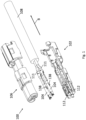
- Fig. 1 depicts an exploded view of a high-speed data connector assembly 100 according to an embodiment of the present disclosure.
- the connector assembly 100 in particular a female connector, includes a first insulating half shell 102, a second insulating half shell 106 and a pair of electrical terminals 104.
- the first insulating half shell 102 includes two clamping receptacles 112 configured to receive the two electrical terminals 104, wherein each of the two electrical terminals 104 may be pressed into a respective clamping receptacle 112 of the first insulating half shell 102.
- the two clamping receptacles 112 and the two electrical terminals 104 are elongated in an axial direction B.
- the second insulating half shell 106 is complementary to the first insulating half shell 102, i.e. the first insulating half shell 102 and the second insulating half shell 106 may be snapped together to form a shell that encloses the two electrical terminals 104 entirely in an assembled state of the connector assembly 100.
- Each of the two electrical terminals 104 may include a fixing element 138.
- the fixing element 138 may be configured to secure the respective electrical terminal 104 in the respective clamping receptacle 112 of the first insulating half shell 102 against a movement in the axial direction B when the respective electrical terminal 104 is inserted in the respective clamping receptacle 112.
- Wires 111 of a cable 108 are connected to the electrical terminals 104, in particular, electrical conductors 110 (not shown in Fig. 1 ) of the wires 111 are connected via crimping to the electrical terminals 104.
- Fig. 2 shows a perspective view of a first insulating half shell 102 according to an embodiment.
- the first insulating half shell 102 may include a first portion 103 and a second portion 105.
- the first portion 103 of the first insulating half shell 102 includes the two clamping receptacles 112.
- Each of the two clamping receptacles 112 includes a groove 113, wherein an elongated wall 136 protrudes at each side of the respective groove 113.
- the two elongated walls 136 of the respective clamping receptacle 112 form an opening to receive the respective electrical terminal 104.
- Each of the elongated walls 136 is curved in a radial direction such that the opening is smaller than a diameter of the electrical terminal 104.
- each of the clamping receptacles 112 includes a recess 134 configured to receive the fixing element 138 (see Fig. 1 ) of the respective electrical terminal 104.
- the first insulating half shell 102 further includes snap means 114 and locking means 118.
- the snap means 114 and the locking means 118 are located at an outer circumferential wall 116 of the first insulating half shell 102.
- the snap means 114 of the first insulating half shell 102 include at least one ledge 121 (see Fig. 6B ).
- the at least one ledge 121 extends in the axial direction B of the first insulating half shell 102.
- the first portion 103 of the first insulating half shell 102 includes two snap means 114 and two locking means 118.
- the respective two snap means 114 are oppositely arranged at the outer circumferential wall 116 of the first portion 103.
- the respective two locking means 118 are also oppositely arranged at the outer circumferential wall 116 of the first portion 103.
- the two locking means 118 of the first portion 103 are arranged in the axial direction B adjacent to the two snap means 114 of the first portion 103.
- the second portion 105 of the first insulating half shell 102 includes two snap means 114 and four locking means 118.
- the respective two snap means 114 are oppositely arranged at the outer circumferential wall 116 of the second portion 105.
- the respective two locking means 118 are also oppositely arranged at the outer circumferential wall 116 of the second portion 105, wherein the two other locking means 118 of the second portion 105 are arranged in the axial direction B adjacent to the two snap means 114 of the second portion 105 and the two other locking means 118 are arranged at an end of the second portion 105 of the first insulating half shell 102.
- the first insulating half shell 102 further includes a triangular rib 130.
- the rib 130 is located between the first portion 103 of the first insulating half shell 102 and the second portion 105 of the first insulating half shell 102 at an inner surface of the first insulating half shell 102.
- the rib 130 will be described in more detail further below.
- Fig. 3 shows a perspective view of the second insulating half shell 106 according to an embodiment.
- the second insulating half shell 106 may include a first portion 107 and a second portion 109.
- the second insulating half shell 106 includes snap means 114 and locking means 118.
- the snap means 114 and the locking means 118 are located at an outer circumferential wall 116 of the second insulating half shell 106.
- the snap means 114 and the locking means 118 of the second insulating half shell 106 may be complementary to the snap means 114 and the locking means 118 of the first insulating half shell 102.
- the first portion 107 of the second insulating half shell 106 includes two snap means 114 and two locking means 118.
- the respective two snap means 114 are oppositely arranged at the outer circumferential wall 116 of the first portion 107 of the second insulating half shell 106.
- the respective two locking means 118 are also oppositely arranged at the outer circumferential wall 116 of the first portion 107 of the second insulating half shell 106.
- the second portion 109 of the second insulating half shell 106 includes two snap means 114 and four locking means 118.
- the respective two snap means 114 are oppositely arranged at the outer circumferential wall 116 of the second portion 109 of the second insulating half shell 106.
- the respective two locking means 118 are also oppositely arranged at the outer circumferential wall 116 of the second portion 109 of the second insulating half shell 106.
- the two other locking means 118 of the second portion 109 are arranged at an end of the second portion 109 of the second insulating half shell 106.
- the snap means 114 of the second insulating half shell 106 includes a hook 120.
- the hook 120 includes a first section 122 and a second section 124 connected by means of a sliding ramp 126.
- Some of the locking means 118 of the second insulating half shell 106 may be integrated in the hook 120 of the snap means 114 of the second insulating half shell 106.
- each of the four snap means 114 of the second insulating half shell 106 includes a respective locking means 118.
- the locking means 118 of the respective snap means 114 may be a bulge 119 at an edge of the second section 124 of the hook 120.
- the hook 120 is configured to hook in the at least one ledge 121 (see Fig. 6B ) of the first insulating half shell 102 to lock the first insulating half shell 102 to the second insulating half shell 106 in a first direction A (see Fig. 4A ).
- the second insulating half shell 106 further includes a triangular rib 130.
- the rib 130 is located between the first portion 107 of the second insulating half shell 106 and the second portion 109 of the second insulating half shell 106 at an inner surface of the second insulating half shell 106.
- the rib 130 of the second insulating half shell 106 will be described in more detail together with the rib 130 of the first insulating half shell 102 further below.
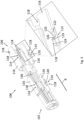
- Fig. 4A shows a perspective view of the high-speed data connector assembly 100 in a pre-assembled state according to an embodiment.
- a cable 108 including a pair of twisted wires 111 is inserted into the first insulating half shell 102 of the high-speed data connector assembly 100.
- One end of the cable 108 is clamped into the second portion 105 of the first insulating half shell 102.
- Each of the wires 111 is covered by a wire insulating.
- Each of the wires 111 includes an electrical conductor 110 that is connected to the respective electrical terminal 104.
- the two electrical terminals 104 are inserted in the clamping receptacles 112 of the first portion 103 of the first insulating half shell 102.
- the walls 136 of the clamping receptacles 112 hold the electrical terminals 104 in the clamping receptacles 112.
- the rib 130 of the first insulating half shell 102 is configured to separate the two electrical conductors 110, in particular the two isolated wires 111.
- the rib 130 substantially completely fills a space between the two electrical conductors 110 in an assembled state of the high-speed data connector assembly 100.
- the second insulating half shell 106 is not snapped on the first insulating half shell 102 in the pre-assembled state of the high-speed data connector assembly 100.
- the second insulating half shell 106 is moved in the first direction A to connect the second insulating half shell 106 with the first insulating half shell 102.
- Fig. 4B shows a perspective view of the high-speed data connector assembly 100 in a pre-locked state according to an embodiment.
- the snapping between the first insulating half shell 102 and the second insulating half shell 106 only locks a movement in the first direction A between the first insulating half shell 102 and the second insulating half shell 106 while still allowing a shifting of the second insulating half shell 106 relative to the first insulating half shell 102 in a second direction B.
- the second direction B is transverse to the first direction A, wherein the second direction B is the axial direction of the first insulating half shell 102 and the second insulating half shell 106.
- the first insulating half shell 102 and the second insulating half shell 106 are arranged axially offset in the second direction B in the pre-locked state of the high-speed data connector assembly 100.
- the second insulating half shell 106 is shifted relative to the first insulating half shell 102 in the second direction B.
- the triangular rib 130 of the second insulating half shell 106 slides in between the two wires 111 when shifting the second insulating half shell 106 relatively to the first insulating half shell 102 in the second direction B.
- a well-controlled and specific wire routing from a pitch between the wires 111 in the cable 108 to a pitch of a connection between the electrical conductors 110 and the electrical terminals 104 within the first insulating half shell 102 and the second insulating half shell 106 is achieved.
- An assembly of the cable 108 to the electrical terminals 104 with crimped electrical conductors 110 within the first insulating half shell 102 is not hindered and remains easy and risk free.
- a space around the wires 111 can be tightened in order to reduce clearances and/or tolerances which may be needed for or might come from a vertical mounting of the cable 108 with the crimped signal contacts inside the first insulating half shell 102.
- Fig. 4C shows a perspective view of the high-speed data connector assembly 100 in the assembled state according to an embodiment.
- the locking means 118 of the first insulating half shell 102 and the locking means 118 of the second insulating half shell 106 gear into each other and lock the first insulating half shell 102 and the second insulating half shell 106 against a movement in the second direction B. Details of the snapping and the locking between the first insulating half shell 102 and the second insulating half shell 106 are described in the following.
- the rib 130 of the first insulating half shell 102 and the rib 130 of the second insulating half shell 106 are aligned.
- the aligned rib 130 substantially completely fills a space between the two electrical conductors 110 (see Fig. 4A ), in particular a space between the two wires 111 of the cable 108, in the assembled state of the high-speed data connector assembly 100.
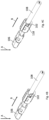
- Fig. 5A shows a side view of the high-speed data connector assembly 100 in the pre-locked state of Fig. 4B .
- the second insulating half shell 106 is snapped onto the first insulating half shell 102 by means of the snap means 114 of the first insulating half shell 102 and the snap means 114 of the second insulating half shell 106.
- the second insulating half shell 106 is shiftable relative to the first insulating half shell 102 in the second direction B.
- the locking means 118 of the first insulating half shell 102 and the locking means 118 of the second insulating half shell 106 are not interlocked in the pre-locked state of the high-speed data connector assembly 100.
- Fig. 5B shows a side cross-sectional view of the high-speed data connector assembly 100 in the pre-locked state of Fig. 4B .
- the snap means 114 of the first insulating half shell 102 and the snap means 114 of the second insulating half shell 106 are engaged.
- the snap means 114 of the first insulating half shell 102 includes a first gap 123.
- a part of the hook 120 in particular the bulge 119 of the locking means 118 (see Fig. 3 ) is located in the first gap 123 of the first insulating half shell 102 in the pre-locked state of the high-speed data connector assembly 100.
- the snap means 114 of the first portion 103 and the snap means 114 of the second portion 105 of the first insulating half shell 102 operate similarly. More details of the snap means 114 are shown in Fig. 6A to 6C .
- Fig. 6A shows a top view of the high-speed data connector assembly 100 in the pre-locked state of Fig. 4B .
- Fig. 6B shows a cross-sectional view of a sectional plane V-V passing through the snap means 114 of the first portions 103, 107 of the first insulating half shell 102 and the second insulating half shell 106, as indicated in Fig. 6A.
- Fig. 6C shows a cross-sectional view of a sectional plane U-U passing through the snap means 114 of the second portions 105, 109 of the first insulating half shell 102 and the second insulating half shell 106, as indicated in Fig. 6A .
- the hook 120 of the snap means 114 of the second insulating half shell 106 and the ledge 121 of the snap means 114 of the first insulating half shell 102 may define an overlap between the at least one hook 120 and the at least one ledge 121 when snapped in place.
- the overlap increases when the second insulating half shell 106 is shifted relative to the first insulating half shell 102 from the pre-locked state (see Fig. 4B ) to the assembled state (see Fig. 4C ) in the second direction B.
- Fig. 7A shows a side view of the high-speed data connector assembly 100 in the assembled state of Fig. 4C .
- the second insulating half shell 106 is snapped onto the first insulating half shell 102 by means of the snap means 114 of the first insulating half shell 102 and the snap means 114 of the second insulating half shell 106.
- the second insulating half shell 106 has been shifted relative to the first insulating half shell 102 in the second direction B from the pre-locked state (see Fig. 4B ) to the assembled state (see Fig. 4C ).
- the locking means 118 of the first insulating half shell 102 and the locking means 118 of the second insulating half shell 106 are interlocked.
- Fig. 7B shows a side cross-sectional view of the high-speed data connector assembly 100 in the assembled state of Fig. 4C .
- the snap means 114 of the first insulating half shell 102 and the snap means 114 of the second insulating half shell 106 are engaged.
- the snap means 114 of the first insulating half shell 102 includes a second gap 125. While moving the second insulating half shell 106 relative to the first insulating half shell 102 in the second direction B, the snap means 114 of the second insulating half shell 106, in particular the hook 120 (see Fig. 3 ) is moved from the first gap 123 into the second gap 125 of the first insulating half shell 102.
- the locking means 118 of the second insulating half shell 106 that are integrated in the hook 120 of the snap means 114 of the second insulating half shell 106, in particular the bulge 119, are shifted from the first gap 123 into the second gap 125 when moving the second insulating half shell 106 in the second direction B by the sliding ramp 126 between the first section 122 and the second section 124 of the hook 120.
- the sliding ramp 126 is moved over an edge of the first gap 123 and, thus, lifting the bulge 119 out of the first gap 123.
- the locking means 118 of the hook 120 is located in the second gap 125 of the first insulating half shell 102.
- the bulge 119 of the hook 120 is located in the second gap 125 of the first insulating half shell 102 in the assembled state of the high-speed data connector assembly 100.
- the other two of the locking means 118 of the first insulating half shell 102 that are arranged at an end of the second portion 105 of the first insulating half shell 102 are received by a slot 127 of the second insulating half shell 106 in the assembled state.
- the first insulating half shell 102 and the second insulating half shell 106 are locked in the first direction A and in the second direction, or axial direction A, in the assembled state.
- This locking means 118 of the first insulating half shell 102 and the respective slot 127 of the second insulating half shell 106 are configured to lock the first insulating half shell 102 to the second insulating half shell 106 in the second direction B when this locking means 118 of the first insulating half shell 102 is received by the slot 127 of the second insulating half shell 106.
- the first insulating half shell 102 and the second insulating half shell 106 are not moveable relatively to each other in the assembled state.
- first insulating half shell 102 and the second insulating half shell 106 are also not moveable in a third direction relatively to each other in the assembled state of the high-speed data connector assembly 100, wherein the third direction is a direction perpendicular to the first direction A and to the second direction B.
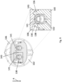
- Fig. 8A shows a cross-sectional view of the high-speed data connector assembly 100 according to an embodiment.
- Each of the at least two electrical terminals 104 includes a fixing element 138 configured to fix the respective electrical terminal 104 in the first insulating half shell 102 against a movement in the second direction B.
- the fixing element 138 is configured to be inserted in the recess 134 of the first insulating half shell 102, in particular, the fixing element 138 may be press-fitted into the recess of the first portion 103 of the first insulating half shell 102.
- the fixing element 138 may be configured to eliminate or to reduce a rotational motion of the electrical terminals 104 around an axis defined by the second direction B, which otherwise could be present due to remaining stress in the untwisted wires 111 of the cable 108.
- a SI common mode performance can be boosted and a damage of a lead-in tulip 137 of the electrical terminals 104 can be prevented during the assembly of the high-speed data connector assembly 100.
- the SI common mode performance may be a performance of common mode signals, wherein the signals flow through two cables 108 or two electrical conductors in the same direction and phase.
- the cable 108 connected to that electrical conductor 110 may be out of position. That may cause an unsymmetrical cable position and, consequently, a signal on one of the cables 108 may be faster than a signal on the respective other one of the cables 108 when the signals flow through the cables 108 (common mode, or differential mode). Since each signal creates an electromagnetic wave that affects the environment of the cable 108, the signal on one of the cables 108 creates a disturbance for the signal on the respective other one of the cables 108. When the cables 108 are symmetrically positioned as described herein, this disturbance effect may be annihilated.
- Fig. 8B shows a top view of electrical terminals 104 inserted in the clamping receptacles 112 of the first insulating half shell 102 of the high-speed data connector assembly 100 according to an embodiment.
- Fig. 8C shows a cross-sectional view of a sectional plane W-W passing through the fixing elements 138 of the electrical terminal 104, as indicated in Figs. 8A and 8B .
- the electrical terminals 104 which are connected to the electrical conductors 110 of the cable 108 (see Fig. 4A ), may be inserted at an angle 135 in the clamping receptacles 112 of the first insulating half shell 102 due to stress in the twisted pair of wires 111.
- the angle 135 may be 0° to 45° between a vertical axis of the clamping receptacles 112 and a tangent of an outer surface of the fixing element 138 as shown in Fig. 8C . In an embodiment, the angle 135 may be 5° to 35°, preferably 10° to 20°, between a vertical axis of the clamping receptacles 112 and a tangent of an outer surface of the fixing element 138.
- the fixing element 138 may include a gap 133. It is understood that in another embodiment the fixing element 138 may not include a gap 133.
- the electrical terminals 104 may be inserted in the clamping receptacles 112 of the first insulating half shell 102 either by pressing the fixing element 138 manually into the recess 134 of the clamping receptacle 112, for example, by hand, or by pressing the fixing element 134 automatically into the recess 134 of the clamping receptacle 112 using the second insulating half shell 106 when snapping the second insulating half shell 106 onto the first insulating half shell 102.
- the at least two clamping receptacles 112 and/or each of the at least two electrical terminals 104 and/or each of the fixing elements 138 may include guiding surfaces 132, 139 configured to align the electrical terminals 104 and the fixing elements 138 in the clamping receptacles 112. After pressing the fixing elements 138 into the recess 134 of the clamping receptacles 112, the fixing elements 138 are arranged aligned and therefore also the electrical terminals 104 are arranged aligned in the clamping receptacles 112 of the first insulating half shell 102.
- Fig. 9 shows a further cross-sectional view of the fixing elements 138 of the electrical terminals 104 in an assembled state of the high-speed data connector assembly 100 according to an embodiment.
- the second insulating half shell 106 includes at least two protrusions 141 arranged at an inner surface of the second insulating half shell 106.
- the protrusions 141 are configured to press the fixing elements 138, and thus the at least two electrical terminals 104, into the at least two clamping receptacles 112, in particular into the recesses 132 of the clamping receptacles 112, when the second insulating half shell 106 is moved in the first direction A.
- the second insulating half shell 106 further includes at least one wedge 143 arranged at the inner surface of the second insulating half shell 106.
- the wedge 143 is configured to press the at least one wall 136 of each clamping receptacle 112 in a direction towards the electrical terminal 104 or towards the fixing element 138 inserted in the respective clamping receptacle 112 when the second insulating half shell 106 is moved in the first direction A.
- Fig. 10A shows a perspective view of a fixing element 138 having clamping elements according to an embodiment.
- Fig. 10B shows a side view and Fig. 10C shows a top view of the fixing element of Fig. 10A .
- the fixing element 138 includes at least one clamping element arranged at an outer surface 144 of the fixing element 138.
- the clamping element may be a bent tongue 140.
- the tongue 140 is bent in a radial direction outwards the fixing element 138.
- the tongue is formed from the fixing element 138 itself, i.e. a part of the outer surface 144 of the fixing element 138 and is bent outwards such that this part forms the tongue 140.
- the tongue 140 is configured to fix the fixing element 138, and thus the respective electrical terminal 104 in the respective clamping receptacle 112.
- Fig. 11A shows a perspective view of a fixing element 138 having clamping elements according to another embodiment.
- Fig. 11B shows a side view and Fig. 11C shows a top view of the fixing element 138 of Fig. 11A .
- the fixing element 138 of this embodiment includes at least one clamping element arranged at an outer surface 144 of the fixing element 138.
- the clamping element may be a bent edge 142.
- the edge 142 is bent in a radial direction outwards the fixing element 138.
- the edge is formed from the fixing element 138 itself, i.e. a part of the outer surface 144 of the fixing element 138 is bent outwards such that this part forms the edge 142.
- the edge 142 is configured to fix the fixing element 138, and thus the respective electrical terminal 104 in the respective clamping receptacle 112.
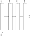
- Fig. 12 shows a flow diagram 200 illustrating a method for assembling a high-speed data connector assembly 100 according to various embodiments.
- at least two electrical terminals 104 may be clamped into at least two clamping receptacles 112 of a first insulating half shell 102.
- the first insulating half shell 102 may be snapped onto a second insulating half shell 106 in a first direction A using a snap means 114.
- the second insulating half shell 106 may be shifted relative to the first insulating half shell 102 in a second direction B transverse to the first direction A.
- the first insulating half shell 102 and the second insulating half shell 106 may be locked against a movement in the second direction B using locking means 118.
Landscapes
- Engineering & Computer Science (AREA)
- Manufacturing & Machinery (AREA)
- Details Of Connecting Devices For Male And Female Coupling (AREA)
Abstract
Description
- The present disclosure relates to a high-speed data connector assembly and a method for assembling the high-speed data connector assembly.
- Examples of high-speed data connector assemblies for differential pair signal transmission are sold by a company called "Rosenberger Hochfrequenztechnik GmbH & Co. KG" under the trademark H-MTD® - High-Speed Modular Twisted-Pair Data.
- Applications for such high-speed data connectors are 4K camera systems, autonomous driving, radar, lidar, high resolution displays and rear seat entertainment. Versions of such connectors are designed to operate at frequencies up to 20 GHz while having a small package size.
- In such high-speed applications, every tenth of a millimeter of the interconnection channel and of the signal connectors should be within a certain data transmission (differential) impedance bandwidth (typical 100 +/- 5 Ω) and should be matched to preceding and succeeding sections. To this end, in each of these sections, metal portions of an inner contact or signal contact and an outer contact or shielding, insulating material of an insulating element and any air gaps should be balanced in size and position with respect to each other. There is also a need for these components to meet other non-signal-integrity requirements, in particular mechanical requirements. For example, it has to be ensured that the high-speed data connector assembly will be securely closed during assembly and remains securely closed during operation. In particular, the closure has to be resistant to any vibrations. To achieve a secure closure of the high-speed data connector assembly, an easy and trustable assembling process has to be provided.
- Accordingly, there is a need to provide a high-speed data connector assembly that is easy and secure to assemble and that provides a secure closure during operation.
- This demand is satisfied by a high-speed data connector assembly according to
claim 1 and a method for assembling the high-speed data connector assembly according to claim 15. - The present disclosure provides a high-speed data connector assembly according to
claim 1 and a method for assembling the high-speed data connector assembly according to claim 15. Embodiments are given in the dependent claims, the description and the drawings. - In one aspect, the present disclosure is directed at a high-speed data connector assembly, wherein the connector assembly comprises a first insulating half shell having at least two clamping receptacles, at least two electrical terminals inserted in the clamping receptacles, a second insulating half shell complementary to the first half shell, snap means configured to snap the first insulating half shell onto the second insulating half shell in a first direction while still allowing a shifting of the second insulating half shell relative to the first insulating half shell in a second direction transverse to the first direction, and locking means configured to lock the first insulating half shell and the second insulating half shell against a movement in the second direction.
- The high-speed data connector assembly described herein may be a female connector assembly, i.e. the electrical terminals may be female signal contacts. Each of the at least two electrical terminals may have a funnel-shaped end section allowing for pin movement, i.e. allowing insertion of a male signal contact pin.
- The first insulating half shell and the second insulating half shell entirely enclose the electrical terminals in an assembled state of the connector assembly, wherein the first insulating half shell and the second insulating half shell are securely locked in the assembled state. Further, the first insulating half shell and the second insulating half shell are configured to isolate the electrical terminals from each other. Thus, the first insulating half shell and the second insulating half shell are manufactured from an insulating material, e.g. plastic. Each of the at least two clamping receptacles of the first insulating half shell is configured to receive one of the at least two electrical terminals. In particular, the clamping receptacles are configured such that the electrical terminals can be clamped into the clamping receptacles. Each of the clamping receptacles may comprise a tube-like section and two walls extending from the tube-like section and forming an opening. The opening is configured to receive the electrical terminal and the walls are configured to enclose the electrical terminal when it is inserted into the clamping receptacle.
- The first insulating half shell and the second insulating half shell can be connected using the snap means and the locking means, wherein each of the first insulating half shell and the second insulating half shell comprises snap means and locking means. The snap means of the first insulating half shell and the snap means of the second insulating half shell may be complementary, i.e. the snap means of the first insulating half shell may be configured to engage with the snap means of the second insulating half shell to snap the first insulating half shell onto the second insulating half shell in the first direction. The locking means of the first insulating half shell and the locking means of the second insulating half shell may be complementary, i.e. the locking means of the first insulating half shell may be configured to engage with the locking means of the second insulating half shell to lock the first insulating half shell and the second insulating half shell in the against a movement in the second direction.
- The second direction may be an axial direction of the electrical terminals when inserted in the clamping receptacles of the first insulating half shell. Thus, a movement or a shifting of the second insulating half shell relative to the first insulating half shell in the second direction may be a movement or a shifting of the second insulating half shell in the axial direction of the electrical terminals. The first direction is perpendicular or transverse to the second direction. The electrical terminals may be inserted into the clamping receptacles of the first insulating half shell in the first direction, i.e. in the same direction as the first insulating half shell is snapped onto the second insulating half shell.
- According to an embodiment, the snap means are located at an outer circumferential wall of the first insulating half shell and the second insulating half shell. The snap means of the first insulating half shell are located at an outer surface of the first insulating half shell. The snap means of the second insulating half shell are located at an outer surface of the second insulating half shell. Thus, after assembly of the first insulating half shell and the second insulating half shell, it can be seen from the outside whether the first insulating half shell has been correctly snapped onto the second insulating half shell.
- According to an embodiment, the snap means comprises at least one hook and at least one ledge configured to define an overlap between the at least one hook and the at least one ledge when snapped in place, wherein the overlap increases when shifting the second insulating half shell relative to the first insulating half shell in the second direction. The at least one hook and the at least one ledge may be elongated in the second direction, i.e. the at least one hook and the at least one ledge may extend in the second direction. The at least one hook may be the snap means of the second insulating half shell. The at least one ledge may be the snap means of the first insulating half shell. The at least one ledge of the first insulating half shell and the at least one hook of the second insulating half shell may be located complementary on the outer surface of the first insulating half shell and the outer surface of the second insulating half shell such that the at least one hook may engage to the at least one ledge when the first insulting half shell is snapped onto the second insulating half shell.
- The first insulating half shell may comprise two oppositely arranged ledges at the outer surface of the first insulating half shell. The second insulating half shell may comprise two oppositely arranged hooks at the outer surface of the second insulating half shell. The first insulating half shell may preferably comprise four ledges, two of the four ledges being arranged opposite each other. The second insulating half shell may preferably comprise four hooks, two of the four hooks being arranged opposite each other. Two oppositely arranged ledges are located at a distance from the other two oppositely arranged ledges in the second direction. Two oppositely arranged hooks are located at a distance from the other two oppositely arranged hooks in the second direction. A secure snapping of the first insulating half shell onto the second insulating half shell can be achieved by multiple snap means arranged at different locations on the outer surface of the first insulating half shell and the second insulating half shell.
- According to this embodiment, the at least one hook comprises a first section and a second section connected by means of a sliding ramp. The first section of the at least one hook and the second section of the at least one hook may comprise a different elongation in a third direction, wherein the third direction is perpendicular to the first direction and to the second direction. The sliding ramp arranged between the first section and the second section of the at least one hook connects the first section and the second section. The sliding ramp is configured to enable a movement of the second insulating half shell relative to the first insulating half shell in the second direction from a pre-locked state of the connector assembly into the assembled state of the connector assembly as will be described below. The different elongation of the first section and the second section may allow to increase an overlap between the at least one hook and the at least one ledge when the second insulating half shell is shifted relative to the first insulating half shell in the second direction. A minimum overlap between the at least one hook of the second insulating half shell and the at least one ledge of the first insulating half shell in the pre-locked state may be necessary in order to generate sufficient retention force between the first insulating half shell and the second insulating half shell and on the other hand not to cause extended stress during an assembly process of the first insulating half shell and the second insulating half shell. In addition, the minimum overlap between the at least one hook of the second insulating half shell and the at least one ledge of the first insulating half shell in the pre-locked state may allow the first insulating half shell and the second insulating half shell to separate from one another. After shifting the second insulating half shell relative to the first insulating half shell in the second direction into the assembled state, i.e. a locked position, the overlap may be sufficient to have proper retention between the first insulating half shell and the second insulating half shell. During shifting the second insulating half shell relative to the first insulating half shell in the second direction, no further deflection of the at least one hook in a radial direction may be required. Thus, a connection between the first insulating half shell and the second insulating half shell in the assembled state is safe and stable.
- According to an embodiment, the locking means are integrated in the at least one hook. Thus, the at least one hook may be configured to snap the first insulating half shell onto the second insulating half shell in the first direction while still allowing a shifting of the second insulating half shell relative to the first insulating half shell in the second direction transverse to the first direction, and the at least one hook may be configured to lock the first insulating half shell and the second insulating half shell against a movement in the second direction. Snap means and locking means integrated in the at least one hook may allow a compact construction of the high-speed data connector assembly.
- According to an embodiment, the locking means are located at an outer circumferential wall of the first insulating half shell and the second insulating half shell. The locking means of the first insulating half shell are located at an outer surface of the first insulating half shell. The locking means of the second insulating half shell are located at an outer surface of the second insulating half shell. Thus, after assembly of the first insulating half shell and the second insulating half shell, it can be seen from the outside whether the first insulating half shell and the second insulating half shell has been correctly locked against a movement in the second direction.
- According to an embodiment, electrical conductors are connected to the electrical terminals and the first insulating half shell and/or the second insulating half shell comprise a rib configured to separate the electrical conductors, wherein the rib substantially completely fills a space between the two electrical conductors in an assembled state of the high-speed data connector assembly. The electrical conductors may be uninsulated wires of a cable connected to the high-speed data connector assembly. The electrical conductors may be connected to the electrical terminals by crimping, welding, soldering, or the like.
- The rib may be of an insulating material, preferable of the same material as the first insulating half shell and/or the second insulating half shell. The rib may protrude from an inner surface of the first insulating half shell and/or the second insulating half shell in a direction parallel to the first direction. The rib may be configured to balance metal portions of the electrical terminals and insulating material of the first insulating half shell and/or the second insulating half shell and any space or air gaps in size and position with respect to each other. In particular, the space between the two electrical conductors is completely filled by the rib in that the rib of the second insulating half shell is aligned with the rib of the first insulating half shell when the high-speed data connector assembly is in the assembled state. Shifting the second insulating half shell relative to the first insulating half shell in the second direction may shift the rib of the second insulating half shell relative to the rib of the first insulating half shell. A substantially completely filled space between the two electrical conductors may improve data transmission.
- According to an embodiment, each of the at least two electrical terminals comprises a fixing element configured to fix the respective electrical terminal in the first insulating half shell against a movement in the second direction. The fixing element may also be configured to reduce or to fix the respective electrical terminal in the first insulating half shell against a rotational movement around an axis in the second direction. The fixing element may also be configured to compensate different crimping diameters of the electrical conductors. The fixing element may be configured to be the same for a plurality of different electrical terminals or to have the same dimensions for a plurality of different electrical terminals. In other words, the electrical terminals, in particular a crimp portion of the electrical terminals, may have different sizes depending on a size of a cable or depending on the crimping diameter of the electrical conductors connected to the electrical terminals, wherein the size of the fixing element is constant for each of the different electrical terminals. By means of the fixing element, the electrical terminals are securely located in the first insulating half shell. Thus, for example, an optimum electrical and mechanical connection between a male signal contact guided into a corresponding female signal contact, i.e. into the corresponding electrical terminal of the high-speed data connector assembly, can be achieved for high data transmission.
- According to this embodiment, each of the at least two clamping receptacles and/or each of the at least two electrical terminals and/or each of the fixing elements comprise guiding surfaces configured to align the electrical terminals and the fixing elements in the clamping receptacles. The guiding surfaces of the at least two clamping receptacles may be inner surfaces of the respective two walls extending from the tube-like section of each clamping receptacle. The guiding surfaces of the at least two electrical terminals and/or the fixing elements may be an outer surface of the at least two electrical terminals and/or the fixing elements. An alignment of the electrical terminal and the fixing elements in the clamping receptacles may be provided in that the outer surfaces of the electrical terminal and the fixing elements adapt to the inner surfaces of the clamping receptacles when the electrical terminals and the fixing elements are inserted in the clamping receptacles. This may facilitate an assembly of the high-speed data connector assembly since the electrical terminals can be inserted at an angle, for example between 0 and 40 degrees, to the respective clamping receptacles while self-aligning during assembly.
- According to an embodiment, the second insulating half shell comprises at least two protrusions arranged at an inner surface of the second insulating half shell and configured to press the fixing elements, and thus the at least two electrical terminals, into the at least two clamping receptacles when the second insulating half shell is moved in the first direction. The two protrusions may be of the same insulating material as the second insulating half shell. Further, the two protrusions may be located at the inner surface of the second insulating half shell corresponding to the respective fixing element of the electrical terminal such that each of the two protrusions can press the respective fixing element, and thus the respective electrical terminal, into the clamping receptacle. Thus, the electrical terminals may be inserted into the clamping receptacles of the first insulating half shell automatically by means of the protrusions when the first insulating half shell is snapped onto the second insulating half shell in the first direction. The protrusions may also assist to align the electrical terminals in the clamping receptacles.
- According to an embodiment, the second insulating half shell comprises at least one wedge arranged at the inner surface of the second insulating half shell and configured to press at least one wall of each clamping receptacle in a direction towards the electrical terminal inserted in the respective clamping receptacle when the second insulating half shell is moved in the first direction. The at least one wedge may be of the same insulating material as the second insulating half shell. Further, the at least one wedge may be located at the inner surface of the second insulating half shell at a corresponding location to a space between the at least two clamping receptacles of the first insulating half shell such that the at least one wedge can press against at least one wall of each clamping receptacle in a direction towards the electrical terminal when the second insulating half shell is snapped onto the first insulating half shell. Thus, the electrical terminals may further be fixed in the clamping receptacles by pressing the at least one wedge against the walls of the clamping receptacles and/or by pressing the protrusions against the fixing element of the respective electrical terminal.
- According to an embodiment, each of the fixing elements comprises at least one clamping element arranged on an outer surface of each of the fixing elements and configured to fix each of the fixing elements, and thus each of the respective electrical terminal in the respective clamping receptacle. The at least one clamping element may protrude in the third direction, i.e. in a direction transverse to the second direction and perpendicular to the first direction. The at least one clamping element of each of the fixing elements is configured to clamp the fixing element against the walls and/or the tube-like section of the respective clamping receptacle. The at least one clamping element may form an outer metal edge of the respective fixing element. Further, the at least one clamping element may provide more grip and retention of the fixing element to the respective clamping receptacle.
- According to an embodiment, the at least one clamping element comprises a bent tongue or a bent edge. The bent tongue or the bent edge may comprise hooking or sharp features. The fixing element may comprise two clamping elements, wherein the two clamping elements are oppositely arranged at an outer surface of the fixing element. In another embodiment, the fixing element may comprise four clamping elements, wherein respective two clamping elements are oppositely arranged at an outer front edge and/or an outer back edge of the fixing element.
- According to an embodiment, the high-speed data connector assembly comprises at least four snap means and at least six locking means.
- In another aspect, the present disclosure is directed at a method for assembling the high-speed data connector assembly according to any of the preceding claims, comprising: clamping the at least two electrical terminals into the at least two clamping receptacles of the first insulating half shell; snapping the first insulating half shell onto the second insulating half shell in the first direction using the snap means; shifting the second insulating half shell relative to the first insulating half shell in the second direction transverse to the first direction; and locking the first insulating half shell and the second insulating half shell against a movement in the second direction using the locking means.
- Exemplary embodiments and functions of the present disclosure are described herein in conjunction with the following drawings showing:
- Fig. 1
- an exploded view of a high-speed data connector assembly according to an embodiment;
- Fig. 2
- a perspective view of a first insulating half shell according to an embodiment;
- Fig. 3
- a perspective view of a second insulating half shell according to an embodiment;
- Fig. 4A
- a perspective view of the high-speed data connector assembly in a pre-assembled state according to an embodiment;
- Fig. 4B
- a perspective view of the high-speed data connector assembly in a pre-locked state according to an embodiment;
- Fig. 4C
- a perspective view of the high-speed data connector assembly in an assembled state according to an embodiment;
- Fig. 5A
- a side view of the high-speed data connector assembly in the prelocked state of
Fig. 4B ; - Fig. 5B
- a side cross-sectional view of the high-speed data connector assembly in the pre-locked state of
Fig. 4B ; - Fig. 6A
- a top view of the high-speed data connector assembly in the prelocked state of
Fig. 4B ; - Fig. 6B
- a cross-sectional view of the high-speed data connector assembly in the pre-locked state of
Fig. 6A ; - Fig. 6C
- a further cross-sectional view of the high-speed data connector assembly in the pre-locked state of
Fig. 6A ; - Fig. 7A
- a side view of the high-speed data connector assembly in the assembled state of
Fig. 4C ; - Fig. 7B
- a side cross-sectional view of the high-speed data connector assembly in the assembled state of
Fig. 4C ; - Fig. 8A
- a cross-sectional view of the high-speed data connector assembly according to an embodiment;
- Fig. 8B
- a top view of electrical terminals inserted in the clamping receptacles of the first insulating half shell of the high-speed data connector assembly according to an embodiment;
- Fig. 8C
- a cross-sectional view of fixing elements of the electrical terminals of
Fig. 8A ; - Fig. 9
- a further cross-sectional view of fixing elements of the electrical terminals in an assembled state of the high-speed data connector assembly according to an embodiment;
- Fig. 10A
- a perspective view of a fixing element having clamping elements according to an embodiment;
- Fig. 10B
- a side view of the fixing element of
Fig. 10A ; - Fig. 10C
- a top view of the fixing element of
Fig. 10A ; - Fig. 11A
- a perspective view of a fixing element having clamping elements according to another embodiment;
- Fig. 11B
- a side view of the fixing element of
Fig. 11A ; - Fig. 11C
- a top view of the fixing element of
Fig. 11A ; and - Fig. 12
- a flow diagram illustrating a method for assembling a high-speed data connector assembly according to various embodiments.
- Problems of assembling signal contacts (electrical terminals) in a connector assembly and cable fixation to the connector assembly when, for example, assembled on full auto line may be solved by a first insulating half shell, a second insulating half shell and electrical terminals having fixation features as described herein. The electrical terminals, together with crimped wires, may be assembled into the first insulating half shell and the second insulating half shell. In order to lower the cost of labour and production, both half shells may be clamped together without using any welding, jointing or any other additional process. The first insulating half shell and the second insulating half shell may be fixed by shapes on portions of the first insulating half shell and by shapes on portions of the second insulating half shell, wherein the shapes engage during an assembly process of the connector assembly. The shapes may be snap means and/or locking means as described herein.
- The assembly process is done in two steps. The first assembly step is a pre-assembly stage, wherein the first insulating half shell is placed on the second insulating half shell perpendicular to a wire direction. The second assembly step is an assembly stage, wherein the second insulating half shell is slid relative to the first insulating half shell along the wire direction. During this move clamping shapes on portions of the first insulating half shell slide on clamping shapes on portions of the second insulating half shell. The characteristic for this design is that an overlapping between the clamping shapes of the first insulating half shell and the second insulating half shell at the first assembly step is relatively small. However, the overlapping becomes significant during the second assembly step of the assembly process.
- Additionally, on the same portions of the first insulating half shell and the second insulating half shell, where clamping shapes are placed, the features which lock the first insulating half shell to the second insulating half shell against a movement along the wire direction may be placed. Thus, a strong and robust connection between the first insulating half shell and the second insulating half shell may be achieved.
-
Fig. 1 depicts an exploded view of a high-speeddata connector assembly 100 according to an embodiment of the present disclosure. Theconnector assembly 100, in particular a female connector, includes a first insulatinghalf shell 102, a secondinsulating half shell 106 and a pair ofelectrical terminals 104. The firstinsulating half shell 102 includes two clampingreceptacles 112 configured to receive the twoelectrical terminals 104, wherein each of the twoelectrical terminals 104 may be pressed into arespective clamping receptacle 112 of the first insulatinghalf shell 102. The two clampingreceptacles 112 and the twoelectrical terminals 104 are elongated in an axial direction B. The secondinsulating half shell 106 is complementary to the first insulatinghalf shell 102, i.e. the first insulatinghalf shell 102 and the second insulatinghalf shell 106 may be snapped together to form a shell that encloses the twoelectrical terminals 104 entirely in an assembled state of theconnector assembly 100. Each of the twoelectrical terminals 104 may include a fixingelement 138. The fixingelement 138 may be configured to secure the respectiveelectrical terminal 104 in therespective clamping receptacle 112 of the first insulatinghalf shell 102 against a movement in the axial direction B when the respectiveelectrical terminal 104 is inserted in therespective clamping receptacle 112.Wires 111 of acable 108 are connected to theelectrical terminals 104, in particular, electrical conductors 110 (not shown inFig. 1 ) of thewires 111 are connected via crimping to theelectrical terminals 104. -
Fig. 2 shows a perspective view of a first insulatinghalf shell 102 according to an embodiment. The firstinsulating half shell 102 may include afirst portion 103 and asecond portion 105. Thefirst portion 103 of the first insulatinghalf shell 102 includes the twoclamping receptacles 112. Each of the two clampingreceptacles 112 includes agroove 113, wherein anelongated wall 136 protrudes at each side of therespective groove 113. The twoelongated walls 136 of therespective clamping receptacle 112 form an opening to receive the respectiveelectrical terminal 104. Each of theelongated walls 136 is curved in a radial direction such that the opening is smaller than a diameter of theelectrical terminal 104. Further, each of the clampingreceptacles 112 includes arecess 134 configured to receive the fixing element 138 (seeFig. 1 ) of the respectiveelectrical terminal 104. - The first
insulating half shell 102 further includes snap means 114 and locking means 118. The snap means 114 and the locking means 118 are located at an outercircumferential wall 116 of the first insulatinghalf shell 102. There may be four snap means 114 and six locking means 118 arranged at the first insulatinghalf shell 102. The snap means 114 of the first insulatinghalf shell 102 include at least one ledge 121 (seeFig. 6B ). The at least oneledge 121 extends in the axial direction B of the first insulatinghalf shell 102. - The
first portion 103 of the first insulatinghalf shell 102 includes two snap means 114 and two locking means 118. The respective two snap means 114 are oppositely arranged at the outercircumferential wall 116 of thefirst portion 103. The respective two locking means 118 are also oppositely arranged at the outercircumferential wall 116 of thefirst portion 103. The two locking means 118 of thefirst portion 103 are arranged in the axial direction B adjacent to the two snap means 114 of thefirst portion 103. Thesecond portion 105 of the first insulatinghalf shell 102 includes two snap means 114 and four locking means 118. The respective two snap means 114 are oppositely arranged at the outercircumferential wall 116 of thesecond portion 105. The respective two locking means 118 are also oppositely arranged at the outercircumferential wall 116 of thesecond portion 105, wherein the two other locking means 118 of thesecond portion 105 are arranged in the axial direction B adjacent to the two snap means 114 of thesecond portion 105 and the two other locking means 118 are arranged at an end of thesecond portion 105 of the first insulatinghalf shell 102. - The first
insulating half shell 102 further includes atriangular rib 130. Therib 130 is located between thefirst portion 103 of the first insulatinghalf shell 102 and thesecond portion 105 of the first insulatinghalf shell 102 at an inner surface of the first insulatinghalf shell 102. Therib 130 will be described in more detail further below. -
Fig. 3 shows a perspective view of the second insulatinghalf shell 106 according to an embodiment. The secondinsulating half shell 106 may include afirst portion 107 and asecond portion 109. The secondinsulating half shell 106 includes snap means 114 and locking means 118. The snap means 114 and the locking means 118 are located at an outercircumferential wall 116 of the second insulatinghalf shell 106. There may be four snap means 114 and six locking means 118 arranged at the second insulatinghalf shell 106. The snap means 114 and the locking means 118 of the second insulatinghalf shell 106 may be complementary to the snap means 114 and the locking means 118 of the first insulatinghalf shell 102. - The
first portion 107 of the second insulatinghalf shell 106 includes two snap means 114 and two locking means 118. The respective two snap means 114 are oppositely arranged at the outercircumferential wall 116 of thefirst portion 107 of the second insulatinghalf shell 106. The respective two locking means 118 are also oppositely arranged at the outercircumferential wall 116 of thefirst portion 107 of the second insulatinghalf shell 106. Thesecond portion 109 of the second insulatinghalf shell 106 includes two snap means 114 and four locking means 118. The respective two snap means 114 are oppositely arranged at the outercircumferential wall 116 of thesecond portion 109 of the second insulatinghalf shell 106. The respective two locking means 118 are also oppositely arranged at the outercircumferential wall 116 of thesecond portion 109 of the second insulatinghalf shell 106. The two other locking means 118 of thesecond portion 109 are arranged at an end of thesecond portion 109 of the second insulatinghalf shell 106. - The snap means 114 of the second insulating
half shell 106 includes ahook 120. Thehook 120 includes afirst section 122 and asecond section 124 connected by means of a slidingramp 126. Some of the locking means 118 of the second insulatinghalf shell 106 may be integrated in thehook 120 of the snap means 114 of the second insulatinghalf shell 106. In particular, each of the four snap means 114 of the second insulatinghalf shell 106 includes a respective locking means 118. The locking means 118 of the respective snap means 114 may be abulge 119 at an edge of thesecond section 124 of thehook 120. Thehook 120 is configured to hook in the at least one ledge 121 (seeFig. 6B ) of the first insulatinghalf shell 102 to lock the first insulatinghalf shell 102 to the second insulatinghalf shell 106 in a first direction A (seeFig. 4A ). - The second
insulating half shell 106 further includes atriangular rib 130. Therib 130 is located between thefirst portion 107 of the second insulatinghalf shell 106 and thesecond portion 109 of the second insulatinghalf shell 106 at an inner surface of the second insulatinghalf shell 106. Therib 130 of the second insulatinghalf shell 106 will be described in more detail together with therib 130 of the first insulatinghalf shell 102 further below. -
Fig. 4A shows a perspective view of the high-speeddata connector assembly 100 in a pre-assembled state according to an embodiment. Acable 108 including a pair oftwisted wires 111 is inserted into the first insulatinghalf shell 102 of the high-speeddata connector assembly 100. One end of thecable 108 is clamped into thesecond portion 105 of the first insulatinghalf shell 102. Each of thewires 111 is covered by a wire insulating. Each of thewires 111 includes anelectrical conductor 110 that is connected to the respective electrical terminal 104.The twoelectrical terminals 104 are inserted in the clampingreceptacles 112 of thefirst portion 103 of the first insulatinghalf shell 102. Thewalls 136 of the clampingreceptacles 112 hold theelectrical terminals 104 in theclamping receptacles 112. Therib 130 of the first insulatinghalf shell 102 is configured to separate the twoelectrical conductors 110, in particular the twoisolated wires 111. Therib 130 substantially completely fills a space between the twoelectrical conductors 110 in an assembled state of the high-speeddata connector assembly 100. - The second
insulating half shell 106 is not snapped on the first insulatinghalf shell 102 in the pre-assembled state of the high-speeddata connector assembly 100. The secondinsulating half shell 106 is moved in the first direction A to connect the second insulatinghalf shell 106 with the first insulatinghalf shell 102. -
Fig. 4B shows a perspective view of the high-speeddata connector assembly 100 in a pre-locked state according to an embodiment. After moving the second insulatinghalf shell 106 in the first direction A, the first insulatinghalf shell 102 is snapped onto the second insulatinghalf shell 106 in the first direction A using the snap means 114 of the first insulatinghalf shell 102 and the snap means 114 of the second insulatinghalf shell 106. However, the snapping between the first insulatinghalf shell 102 and the second insulatinghalf shell 106 only locks a movement in the first direction A between the first insulatinghalf shell 102 and the second insulatinghalf shell 106 while still allowing a shifting of the second insulatinghalf shell 106 relative to the first insulatinghalf shell 102 in a second direction B. The second direction B is transverse to the first direction A, wherein the second direction B is the axial direction of the first insulatinghalf shell 102 and the second insulatinghalf shell 106. As shown inFig. 4B , the first insulatinghalf shell 102 and the second insulatinghalf shell 106 are arranged axially offset in the second direction B in the pre-locked state of the high-speeddata connector assembly 100. - To bring the high-speed
data connector assembly 100 into an assembled state, i.e. into a final locked position of the high-speeddata connector assembly 100, the second insulatinghalf shell 106 is shifted relative to the first insulatinghalf shell 102 in the second direction B. Thetriangular rib 130 of the second insulating half shell 106 (seeFig. 3 ) slides in between the twowires 111 when shifting the second insulatinghalf shell 106 relatively to the first insulatinghalf shell 102 in the second direction B. Thus, a well-controlled and specific wire routing from a pitch between thewires 111 in thecable 108 to a pitch of a connection between theelectrical conductors 110 and theelectrical terminals 104 within the first insulatinghalf shell 102 and the second insulatinghalf shell 106 is achieved. An assembly of thecable 108 to theelectrical terminals 104 with crimpedelectrical conductors 110 within the first insulatinghalf shell 102 is not hindered and remains easy and risk free. Also, a space around thewires 111 can be tightened in order to reduce clearances and/or tolerances which may be needed for or might come from a vertical mounting of thecable 108 with the crimped signal contacts inside the first insulatinghalf shell 102. Drive the wires in a specific and controlled routing from the pitch in thecable 108 to the pitch of the connection between theelectrical conductors 110 and theelectrical terminals 104 which may be favorable for a differential impedance match and thus, for return loss and/or signal integrity. Also, there may be more freedom to select a material of therib 130 for either differential impedance match and/or creepage distance and/or mechanical strength. -
Fig. 4C shows a perspective view of the high-speeddata connector assembly 100 in the assembled state according to an embodiment. In the assembled state, the locking means 118 of the first insulatinghalf shell 102 and the locking means 118 of the second insulatinghalf shell 106 gear into each other and lock the first insulatinghalf shell 102 and the second insulatinghalf shell 106 against a movement in the second direction B. Details of the snapping and the locking between the first insulatinghalf shell 102 and the second insulatinghalf shell 106 are described in the following. In the assembled state of the high-speeddata connector assembly 100, therib 130 of the first insulatinghalf shell 102 and therib 130 of the second insulatinghalf shell 106 are aligned. The alignedrib 130 substantially completely fills a space between the two electrical conductors 110 (seeFig. 4A ), in particular a space between the twowires 111 of thecable 108, in the assembled state of the high-speeddata connector assembly 100. -
Fig. 5A shows a side view of the high-speeddata connector assembly 100 in the pre-locked state ofFig. 4B . The secondinsulating half shell 106 is snapped onto the first insulatinghalf shell 102 by means of the snap means 114 of the first insulatinghalf shell 102 and the snap means 114 of the second insulatinghalf shell 106. The secondinsulating half shell 106 is shiftable relative to the first insulatinghalf shell 102 in the second direction B. Thus, the locking means 118 of the first insulatinghalf shell 102 and the locking means 118 of the second insulatinghalf shell 106 are not interlocked in the pre-locked state of the high-speeddata connector assembly 100. -
Fig. 5B shows a side cross-sectional view of the high-speeddata connector assembly 100 in the pre-locked state ofFig. 4B . The snap means 114 of the first insulatinghalf shell 102 and the snap means 114 of the second insulatinghalf shell 106 are engaged. The snap means 114 of the first insulatinghalf shell 102 includes afirst gap 123. As shown inFig. 5B , a part of thehook 120, in particular thebulge 119 of the locking means 118 (seeFig. 3 ), is located in thefirst gap 123 of the first insulatinghalf shell 102 in the pre-locked state of the high-speeddata connector assembly 100. The snap means 114 of thefirst portion 103 and the snap means 114 of thesecond portion 105 of the first insulatinghalf shell 102 operate similarly. More details of the snap means 114 are shown inFig. 6A to 6C . -
Fig. 6A shows a top view of the high-speeddata connector assembly 100 in the pre-locked state ofFig. 4B .Fig. 6B shows a cross-sectional view of a sectional plane V-V passing through the snap means 114 of thefirst portions half shell 102 and the second insulatinghalf shell 106, as indicated inFig. 6A. Fig. 6C shows a cross-sectional view of a sectional plane U-U passing through the snap means 114 of thesecond portions half shell 102 and the second insulatinghalf shell 106, as indicated inFig. 6A . Thehook 120 of the snap means 114 of the second insulatinghalf shell 106 and theledge 121 of the snap means 114 of the first insulatinghalf shell 102 may define an overlap between the at least onehook 120 and the at least oneledge 121 when snapped in place. The overlap increases when the second insulatinghalf shell 106 is shifted relative to the first insulatinghalf shell 102 from the pre-locked state (seeFig. 4B ) to the assembled state (seeFig. 4C ) in the second direction B. -
Fig. 7A shows a side view of the high-speeddata connector assembly 100 in the assembled state ofFig. 4C . The secondinsulating half shell 106 is snapped onto the first insulatinghalf shell 102 by means of the snap means 114 of the first insulatinghalf shell 102 and the snap means 114 of the second insulatinghalf shell 106. The secondinsulating half shell 106 has been shifted relative to the first insulatinghalf shell 102 in the second direction B from the pre-locked state (seeFig. 4B ) to the assembled state (seeFig. 4C ). In the assembled state of the high-speeddata connector assembly 100 the locking means 118 of the first insulatinghalf shell 102 and the locking means 118 of the second insulatinghalf shell 106 are interlocked. -
Fig. 7B shows a side cross-sectional view of the high-speeddata connector assembly 100 in the assembled state ofFig. 4C . The snap means 114 of the first insulatinghalf shell 102 and the snap means 114 of the second insulatinghalf shell 106 are engaged. The snap means 114 of the first insulatinghalf shell 102 includes asecond gap 125. While moving the second insulatinghalf shell 106 relative to the first insulatinghalf shell 102 in the second direction B, the snap means 114 of the second insulatinghalf shell 106, in particular the hook 120 (seeFig. 3 ) is moved from thefirst gap 123 into thesecond gap 125 of the first insulatinghalf shell 102. The locking means 118 of the second insulatinghalf shell 106 that are integrated in thehook 120 of the snap means 114 of the second insulatinghalf shell 106, in particular thebulge 119, are shifted from thefirst gap 123 into thesecond gap 125 when moving the second insulatinghalf shell 106 in the second direction B by the slidingramp 126 between thefirst section 122 and thesecond section 124 of thehook 120. The slidingramp 126 is moved over an edge of thefirst gap 123 and, thus, lifting thebulge 119 out of thefirst gap 123. In the assembled state of the high-speeddata connector assembly 100, the locking means 118 of thehook 120 is located in thesecond gap 125 of the first insulatinghalf shell 102. In particular, thebulge 119 of thehook 120 is located in thesecond gap 125 of the first insulatinghalf shell 102 in the assembled state of the high-speeddata connector assembly 100. - Further, the other two of the locking means 118 of the first insulating
half shell 102 that are arranged at an end of thesecond portion 105 of the first insulatinghalf shell 102 are received by aslot 127 of the second insulatinghalf shell 106 in the assembled state. Thus, the first insulatinghalf shell 102 and the second insulatinghalf shell 106 are locked in the first direction A and in the second direction, or axial direction A, in the assembled state. This locking means 118 of the first insulatinghalf shell 102 and therespective slot 127 of the second insulatinghalf shell 106 are configured to lock the first insulatinghalf shell 102 to the second insulatinghalf shell 106 in the second direction B when this locking means 118 of the first insulatinghalf shell 102 is received by theslot 127 of the second insulatinghalf shell 106. Thus, the first insulatinghalf shell 102 and the second insulatinghalf shell 106 are not moveable relatively to each other in the assembled state. It is understood, that the first insulatinghalf shell 102 and the second insulatinghalf shell 106 are also not moveable in a third direction relatively to each other in the assembled state of the high-speeddata connector assembly 100, wherein the third direction is a direction perpendicular to the first direction A and to the second direction B. -
Fig. 8A shows a cross-sectional view of the high-speeddata connector assembly 100 according to an embodiment. Each of the at least twoelectrical terminals 104 includes a fixingelement 138 configured to fix the respectiveelectrical terminal 104 in the first insulatinghalf shell 102 against a movement in the second direction B. The fixingelement 138 is configured to be inserted in therecess 134 of the first insulatinghalf shell 102, in particular, the fixingelement 138 may be press-fitted into the recess of thefirst portion 103 of the first insulatinghalf shell 102. Further, the fixingelement 138 may be configured to eliminate or to reduce a rotational motion of theelectrical terminals 104 around an axis defined by the second direction B, which otherwise could be present due to remaining stress in the untwistedwires 111 of thecable 108. Thus, a SI common mode performance can be boosted and a damage of a lead-intulip 137 of theelectrical terminals 104 can be prevented during the assembly of the high-speeddata connector assembly 100. - The SI common mode performance may be a performance of common mode signals, wherein the signals flow through two
cables 108 or two electrical conductors in the same direction and phase. When at least one of theelectrical conductors 110 or signal contacts is rotated, then thecable 108 connected to thatelectrical conductor 110 may be out of position. That may cause an unsymmetrical cable position and, consequently, a signal on one of thecables 108 may be faster than a signal on the respective other one of thecables 108 when the signals flow through the cables 108 (common mode, or differential mode). Since each signal creates an electromagnetic wave that affects the environment of thecable 108, the signal on one of thecables 108 creates a disturbance for the signal on the respective other one of thecables 108. When thecables 108 are symmetrically positioned as described herein, this disturbance effect may be annihilated. -
Fig. 8B shows a top view ofelectrical terminals 104 inserted in the clampingreceptacles 112 of the first insulatinghalf shell 102 of the high-speeddata connector assembly 100 according to an embodiment.Fig. 8C shows a cross-sectional view of a sectional plane W-W passing through the fixingelements 138 of theelectrical terminal 104, as indicated inFigs. 8A and 8B . Theelectrical terminals 104, which are connected to theelectrical conductors 110 of the cable 108 (seeFig. 4A ), may be inserted at anangle 135 in the clampingreceptacles 112 of the first insulatinghalf shell 102 due to stress in the twisted pair ofwires 111. Theangle 135 may be 0° to 45° between a vertical axis of the clampingreceptacles 112 and a tangent of an outer surface of the fixingelement 138 as shown inFig. 8C . In an embodiment, theangle 135 may be 5° to 35°, preferably 10° to 20°, between a vertical axis of the clampingreceptacles 112 and a tangent of an outer surface of the fixingelement 138. The fixingelement 138 may include agap 133. It is understood that in another embodiment the fixingelement 138 may not include agap 133. Theelectrical terminals 104 may be inserted in the clampingreceptacles 112 of the first insulatinghalf shell 102 either by pressing the fixingelement 138 manually into therecess 134 of the clampingreceptacle 112, for example, by hand, or by pressing the fixingelement 134 automatically into therecess 134 of the clampingreceptacle 112 using the second insulatinghalf shell 106 when snapping the second insulatinghalf shell 106 onto the first insulatinghalf shell 102. The at least two clampingreceptacles 112 and/or each of the at least twoelectrical terminals 104 and/or each of the fixingelements 138 may include guidingsurfaces electrical terminals 104 and the fixingelements 138 in theclamping receptacles 112. After pressing the fixingelements 138 into therecess 134 of the clampingreceptacles 112, the fixingelements 138 are arranged aligned and therefore also theelectrical terminals 104 are arranged aligned in the clampingreceptacles 112 of the first insulatinghalf shell 102. -
Fig. 9 shows a further cross-sectional view of the fixingelements 138 of theelectrical terminals 104 in an assembled state of the high-speeddata connector assembly 100 according to an embodiment. The secondinsulating half shell 106 includes at least twoprotrusions 141 arranged at an inner surface of the second insulatinghalf shell 106. Theprotrusions 141 are configured to press the fixingelements 138, and thus the at least twoelectrical terminals 104, into the at least two clampingreceptacles 112, in particular into therecesses 132 of the clampingreceptacles 112, when the second insulatinghalf shell 106 is moved in the first direction A. The secondinsulating half shell 106 further includes at least onewedge 143 arranged at the inner surface of the second insulatinghalf shell 106. Thewedge 143 is configured to press the at least onewall 136 of each clampingreceptacle 112 in a direction towards theelectrical terminal 104 or towards the fixingelement 138 inserted in therespective clamping receptacle 112 when the second insulatinghalf shell 106 is moved in the first direction A. -
Fig. 10A shows a perspective view of a fixingelement 138 having clamping elements according to an embodiment.Fig. 10B shows a side view andFig. 10C shows a top view of the fixing element ofFig. 10A . The fixingelement 138 includes at least one clamping element arranged at anouter surface 144 of the fixingelement 138. The clamping element may be abent tongue 140. Thetongue 140 is bent in a radial direction outwards the fixingelement 138. The tongue is formed from the fixingelement 138 itself, i.e. a part of theouter surface 144 of the fixingelement 138 and is bent outwards such that this part forms thetongue 140. Thetongue 140 is configured to fix the fixingelement 138, and thus the respectiveelectrical terminal 104 in therespective clamping receptacle 112. -
Fig. 11A shows a perspective view of a fixingelement 138 having clamping elements according to another embodiment.Fig. 11B shows a side view andFig. 11C shows a top view of the fixingelement 138 ofFig. 11A . The fixingelement 138 of this embodiment includes at least one clamping element arranged at anouter surface 144 of the fixingelement 138. The clamping element may be abent edge 142. Theedge 142 is bent in a radial direction outwards the fixingelement 138. The edge is formed from the fixingelement 138 itself, i.e. a part of theouter surface 144 of the fixingelement 138 is bent outwards such that this part forms theedge 142. Theedge 142 is configured to fix the fixingelement 138, and thus the respectiveelectrical terminal 104 in therespective clamping receptacle 112. -
Fig. 12 shows a flow diagram 200 illustrating a method for assembling a high-speeddata connector assembly 100 according to various embodiments. At 202, at least twoelectrical terminals 104 may be clamped into at least two clampingreceptacles 112 of a first insulatinghalf shell 102. At 204, the first insulatinghalf shell 102 may be snapped onto a secondinsulating half shell 106 in a first direction A using a snap means 114. At 206, the second insulatinghalf shell 106 may be shifted relative to the first insulatinghalf shell 102 in a second direction B transverse to the first direction A. At 208, the first insulatinghalf shell 102 and the second insulatinghalf shell 106 may be locked against a movement in the second direction B using locking means 118. -
- 100
- high-speed data connector assembly
- 102
- first insulating half shell
- 103
- first portion of the first insulating half shell
- 104
- electrical terminal
- 105
- second portion of the first insulating half shell
- 106
- second insulating half shell
- 107
- first portion of the second insulating half shell
- 108
- cable
- 109
- second portion of the second insulating half shell
- 110
- electrical conductor
- 111
- wire
- 112
- clamping receptacles
- 113
- groove
- 114
- snap means
- 116
- outer circumferential wall
- 118
- locking means
- 119
- bulge
- 120
- hook
- 121
- ledge
- 122
- first section
- 123
- first gap
- 124
- second section
- 125
- second gap
- 126
- sliding ramp
- 127
- slot
- 130
- rib
- 132
- guiding surface
- 133
- gap
- 134
- recess
- 135
- angle
- 136
- wall
- 137
- lead-in tulip
- 138
- fixing element
- 139
- guiding surface
- 140
- bent tongue
- 141
- protrusion
- 142
- bent edge
- 143
- wedge
- 144
- outer surface
- 200
- flow diagram illustrating a method for assembling a high-speed data connector assembly according to various embodiments
- 202
- step of clamping the at least two electrical terminals into the at least two clamping receptacles of the first insulating half shell
- 204
- step of snapping the first insulating half shell onto the second insulating half shell in the first direction using the snap means
- 206
- step of shifting the second insulating half shell relative to the first insulating half shell in the second direction transverse to the first direction
- 208
- step of locking the first insulating half shell and the second insulating half shell against a movement in the second direction using the locking means
- A
- first direction
- B
- second direction
- T
- section plane
- U
- section plane
- V
- section plane
- W
- section plane
Claims (15)
- A high-speed data connector assembly (100), comprising:a first insulating half shell (102) having at least two clamping receptacles (112),at least two electrical terminals (104) inserted in the clamping receptacles (112),a second insulating half shell (106) complementary to the first half shell,snap means (114) configured to snap the first insulating half shell (102) onto the second insulating half shell (106) in a first direction (A) while still allowing a shifting of the second insulating half shell (106) relative to the first insulating half shell (102) in a second direction (B) transverse to the first direction (A), andlocking means (118) configured to lock the first insulating half shell (102) and the second insulating half shell (106) against a movement in the second direction (B).
- The high-speed data connector assembly (100) according to claim 1,
wherein the snap means (114) are located at an outer circumferential wall (116) of the first insulating half shell (102) and the second insulating half shell (106). - The high-speed data connector assembly (100) according to claim 1 or 2, wherein the snap means (114) comprises at least one hook (120) and at least one ledge (121) configured to define an overlap between the at least one hook (120) and the at least one ledge (121) when snapped in place, wherein the overlap increases when shifting the second insulating half shell (106) relative to the first insulating half shell (102) in the second direction (B).
- The high-speed data connector assembly (100) according to claim 3,
wherein the at least one hook (120) comprises a first section (122) and a second section (124) connected by means of a sliding ramp (126). - The high-speed data connector assembly (100) according to claims 3 or 4, wherein the locking means (118) are integrated in the at least one hook (120).
- The high-speed data connector assembly (100) according to any one of claims 1 to 5,
wherein the locking means (118) are located at an outer circumferential wall (116) of the first insulating half shell (102) and the second insulating half shell (106). - The high-speed data connector assembly (100) according to any one of claims 1 to 6,wherein electrical conductors (110) are connected to the electrical terminals (104), andwherein the first insulating half shell (102) and/or the second insulating half shell (106) comprise a rib (130) configured to separate the electrical conductors (110), wherein the rib (130) substantially completely fills a space between the two electrical conductors (110) in an assembled state of the high-speed data connector assembly.
- The high-speed data connector assembly (100) according to any one of claims 1 to 7,
wherein each of the at least two electrical terminals (104) comprises a fixing element (138) configured to fix the respective electrical terminal (104) in the first insulating half shell (102) against a movement in the second direction (B). - The high-speed data connector assembly (100) according to any one of claim 8,
wherein each of the at least two clamping receptacles (112) and/or each of the at least two electrical terminals (104) and/or each of the fixing elements (138) comprise guiding surfaces (132, 139) configured to align the electrical terminals (104) and the fixing elements (138) in the clamping receptacles (112). - The high-speed data connector assembly (100) according to any one of claims 8 or 9,
wherein the second insulating half shell (106) comprises at least two protrusions (141) arranged at an inner surface of the second insulating half shell (106) and configured to press the fixing elements (138), and thus the at least two electrical terminals (104), into the at least two clamping receptacles (112) when the second insulating half shell (106) is moved in the first direction (A). - The high-speed data connector assembly (100) according to claim 10, wherein the second insulating half shell (106) comprises at least one wedge (143) arranged at the inner surface of the second insulating half shell (106) and configured to press at least one wall (136) of each clamping receptacle (112) in a direction towards the electrical terminal (104) inserted in the respective clamping receptacle (112) when the second insulating half shell (106) is moved in the first direction (A).
- The high-speed data connector assembly (100) according to any one of claims 8 to 11,
wherein each of the fixing elements (138) comprises at least one clamping element arranged on an outer surface of each of the fixing elements (138) and configured to fix each of the fixing elements (138), and thus each of the respective electrical terminal (104) in the respective clamping receptacle (112). - The high-speed data connector assembly (100) according to claim 12, wherein the at least one clamping element comprises a bent tongue (140) or a bent edge (142).
- The high-speed data connector assembly (100) according to any one of claims 1 to 12,
wherein the high-speed data connector assembly (100) comprises at least four snap means (114) and at least six locking means (118). - A method for assembling the high-speed data connector assembly (100) according to any of the preceding claims, comprising:clamping the at least two electrical terminals (104) into the at least two clamping receptacles (112) of the first insulating half shell (102);snapping the first insulating half shell (102) onto the second insulating half shell (106) in the first direction (A) using the snap means (114);shifting the second insulating half shell (106) relative to the first insulating half shell (102) in the second direction (B) transverse to the first direction (A); andlocking the first insulating half shell (102) and the second insulating half shell (106) against a movement in the second direction (B) using the locking means (118).
Priority Applications (3)
| Application Number | Priority Date | Filing Date | Title |
|---|---|---|---|
| EP23172632.4A EP4462608B1 (en) | 2023-05-10 | 2023-05-10 | High-speed data connector assembly |
| US18/656,896 US20240380155A1 (en) | 2023-05-10 | 2024-05-07 | High-speed data connector assembly |
| CN202410568989.XA CN118943802A (en) | 2023-05-10 | 2024-05-09 | High-Speed Data Connector Assemblies |
Applications Claiming Priority (1)
| Application Number | Priority Date | Filing Date | Title |
|---|---|---|---|
| EP23172632.4A EP4462608B1 (en) | 2023-05-10 | 2023-05-10 | High-speed data connector assembly |
Publications (2)
| Publication Number | Publication Date |
|---|---|
| EP4462608A1 true EP4462608A1 (en) | 2024-11-13 |
| EP4462608B1 EP4462608B1 (en) | 2025-09-03 |
Family
ID=86331275
Family Applications (1)
| Application Number | Title | Priority Date | Filing Date |
|---|---|---|---|
| EP23172632.4A Active EP4462608B1 (en) | 2023-05-10 | 2023-05-10 | High-speed data connector assembly |
Country Status (3)
| Country | Link |
|---|---|
| US (1) | US20240380155A1 (en) |
| EP (1) | EP4462608B1 (en) |
| CN (1) | CN118943802A (en) |
Citations (3)
| Publication number | Priority date | Publication date | Assignee | Title |
|---|---|---|---|---|
| FR2952761A1 (en) * | 2009-11-16 | 2011-05-20 | Radiall Sa | MULTICONTACT CONNECTOR |
| DE102018001227A1 (en) * | 2017-03-08 | 2018-09-13 | Autonetworks Technologies, Ltd. | Shielding connection and manufacturing method therefor |
| US20220393387A1 (en) * | 2021-06-07 | 2022-12-08 | Foxconn (Kunshan) Computer Connector Co., Ltd. | Cable connector with improved terminal and wire holding portions |
-
2023
- 2023-05-10 EP EP23172632.4A patent/EP4462608B1/en active Active
-
2024
- 2024-05-07 US US18/656,896 patent/US20240380155A1/en active Pending
- 2024-05-09 CN CN202410568989.XA patent/CN118943802A/en active Pending
Patent Citations (3)
| Publication number | Priority date | Publication date | Assignee | Title |
|---|---|---|---|---|
| FR2952761A1 (en) * | 2009-11-16 | 2011-05-20 | Radiall Sa | MULTICONTACT CONNECTOR |
| DE102018001227A1 (en) * | 2017-03-08 | 2018-09-13 | Autonetworks Technologies, Ltd. | Shielding connection and manufacturing method therefor |
| US20220393387A1 (en) * | 2021-06-07 | 2022-12-08 | Foxconn (Kunshan) Computer Connector Co., Ltd. | Cable connector with improved terminal and wire holding portions |
Also Published As
| Publication number | Publication date |
|---|---|
| EP4462608B1 (en) | 2025-09-03 |
| CN118943802A (en) | 2024-11-12 |
| US20240380155A1 (en) | 2024-11-14 |
Similar Documents
| Publication | Publication Date | Title |
|---|---|---|
| US10707597B2 (en) | Electrical contact device, electrical connecting unit and method for assembling an electrical cable | |
| US8057258B2 (en) | Shielded connector | |
| US11664629B2 (en) | Assembly comprising a connector and a cable | |
| EP0915536B1 (en) | Coaxial connector | |
| EP1003250B1 (en) | A shield connector, a set of shielded connectors and method for connecting a shielded connector with a shielded cable | |
| US11411352B2 (en) | Connector for automotive applications | |
| US12100915B2 (en) | Shielded electrical connector for automotive applications and method of assembling thereof | |
| EP3783741A1 (en) | Connector and assembly for automotive applications | |
| US12580343B2 (en) | High speed, ruggedized connector | |
| EP3783754A1 (en) | Connector for automotive applications | |
| US7029303B2 (en) | Hermaphroditic handle socket assembly and pin assembly | |
| US12322894B2 (en) | Connector assembly with funnel-shaped signal contact end section | |
| EP0993075A2 (en) | Electrical connector with metallic jacket | |
| EP4462608B1 (en) | High-speed data connector assembly | |
| EP4407816A1 (en) | Connector assembly | |
| US11996657B2 (en) | Connector including male and female connectors | |
| US20230198187A1 (en) | Electrical Plug Connector and Method for Assembling an Electrical Plug Connector | |
| EP3982494A2 (en) | Cable harness assembly with a shielded twisted pair cable | |
| US20250316933A1 (en) | Shield connector | |
| US20250007220A1 (en) | Shielding device for electromagnetic shielding | |
| US20240195114A1 (en) | Electrical connector | |
| JP2025158082A (en) | Shielded Connector | |
| US12463390B2 (en) | Plug connector and plug connector system | |
| EP1596475A1 (en) | Electrical connector for braided cables |
Legal Events
| Date | Code | Title | Description |
|---|---|---|---|
| PUAI | Public reference made under article 153(3) epc to a published international application that has entered the european phase |
Free format text: ORIGINAL CODE: 0009012 |
|
| STAA | Information on the status of an ep patent application or granted ep patent |
Free format text: STATUS: THE APPLICATION HAS BEEN PUBLISHED |
|
| AK | Designated contracting states |
Kind code of ref document: A1 Designated state(s): AL AT BE BG CH CY CZ DE DK EE ES FI FR GB GR HR HU IE IS IT LI LT LU LV MC ME MK MT NL NO PL PT RO RS SE SI SK SM TR |
|
| STAA | Information on the status of an ep patent application or granted ep patent |
Free format text: STATUS: REQUEST FOR EXAMINATION WAS MADE |
|
| 17P | Request for examination filed |
Effective date: 20241216 |
|
| GRAP | Despatch of communication of intention to grant a patent |
Free format text: ORIGINAL CODE: EPIDOSNIGR1 |
|
| STAA | Information on the status of an ep patent application or granted ep patent |
Free format text: STATUS: GRANT OF PATENT IS INTENDED |
|
| RIC1 | Information provided on ipc code assigned before grant |
Ipc: H01R 13/41 20060101ALN20250403BHEP Ipc: H01R 13/506 20060101AFI20250403BHEP |
|
| INTG | Intention to grant announced |
Effective date: 20250411 |
|
| GRAS | Grant fee paid |
Free format text: ORIGINAL CODE: EPIDOSNIGR3 |
|
| GRAA | (expected) grant |
Free format text: ORIGINAL CODE: 0009210 |
|
| STAA | Information on the status of an ep patent application or granted ep patent |
Free format text: STATUS: THE PATENT HAS BEEN GRANTED |
|
| P01 | Opt-out of the competence of the unified patent court (upc) registered |
Free format text: CASE NUMBER: UPC_APP_0342_4462608/2025 Effective date: 20250715 |
|
| AK | Designated contracting states |
Kind code of ref document: B1 Designated state(s): AL AT BE BG CH CY CZ DE DK EE ES FI FR GB GR HR HU IE IS IT LI LT LU LV MC ME MK MT NL NO PL PT RO RS SE SI SK SM TR |
|
| REG | Reference to a national code |
Ref country code: CH Ref legal event code: EP |
|
| REG | Reference to a national code |
Ref country code: DE Ref legal event code: R096 Ref document number: 602023006248 Country of ref document: DE |
|
| REG | Reference to a national code |
Ref country code: IE Ref legal event code: FG4D |
|
| REG | Reference to a national code |
Ref country code: NL Ref legal event code: MP Effective date: 20250903 |
|
| PG25 | Lapsed in a contracting state [announced via postgrant information from national office to epo] |
Ref country code: NO Free format text: LAPSE BECAUSE OF FAILURE TO SUBMIT A TRANSLATION OF THE DESCRIPTION OR TO PAY THE FEE WITHIN THE PRESCRIBED TIME-LIMIT Effective date: 20251203 |
|
| REG | Reference to a national code |
Ref country code: LT Ref legal event code: MG9D |
|
| PG25 | Lapsed in a contracting state [announced via postgrant information from national office to epo] |
Ref country code: FI Free format text: LAPSE BECAUSE OF FAILURE TO SUBMIT A TRANSLATION OF THE DESCRIPTION OR TO PAY THE FEE WITHIN THE PRESCRIBED TIME-LIMIT Effective date: 20250903 |
|
| PG25 | Lapsed in a contracting state [announced via postgrant information from national office to epo] |
Ref country code: HR Free format text: LAPSE BECAUSE OF FAILURE TO SUBMIT A TRANSLATION OF THE DESCRIPTION OR TO PAY THE FEE WITHIN THE PRESCRIBED TIME-LIMIT Effective date: 20250903 |
|
| PG25 | Lapsed in a contracting state [announced via postgrant information from national office to epo] |
Ref country code: GR Free format text: LAPSE BECAUSE OF FAILURE TO SUBMIT A TRANSLATION OF THE DESCRIPTION OR TO PAY THE FEE WITHIN THE PRESCRIBED TIME-LIMIT Effective date: 20251204 |
|
| PG25 | Lapsed in a contracting state [announced via postgrant information from national office to epo] |
Ref country code: SE Free format text: LAPSE BECAUSE OF FAILURE TO SUBMIT A TRANSLATION OF THE DESCRIPTION OR TO PAY THE FEE WITHIN THE PRESCRIBED TIME-LIMIT Effective date: 20250903 |
|
| PG25 | Lapsed in a contracting state [announced via postgrant information from national office to epo] |
Ref country code: LV Free format text: LAPSE BECAUSE OF FAILURE TO SUBMIT A TRANSLATION OF THE DESCRIPTION OR TO PAY THE FEE WITHIN THE PRESCRIBED TIME-LIMIT Effective date: 20250903 |
|
| PG25 | Lapsed in a contracting state [announced via postgrant information from national office to epo] |
Ref country code: BG Free format text: LAPSE BECAUSE OF FAILURE TO SUBMIT A TRANSLATION OF THE DESCRIPTION OR TO PAY THE FEE WITHIN THE PRESCRIBED TIME-LIMIT Effective date: 20250903 Ref country code: PL Free format text: LAPSE BECAUSE OF FAILURE TO SUBMIT A TRANSLATION OF THE DESCRIPTION OR TO PAY THE FEE WITHIN THE PRESCRIBED TIME-LIMIT Effective date: 20250903 |
|
| PG25 | Lapsed in a contracting state [announced via postgrant information from national office to epo] |
Ref country code: RS Free format text: LAPSE BECAUSE OF FAILURE TO SUBMIT A TRANSLATION OF THE DESCRIPTION OR TO PAY THE FEE WITHIN THE PRESCRIBED TIME-LIMIT Effective date: 20251203 |
|
| PG25 | Lapsed in a contracting state [announced via postgrant information from national office to epo] |
Ref country code: ES Free format text: LAPSE BECAUSE OF FAILURE TO SUBMIT A TRANSLATION OF THE DESCRIPTION OR TO PAY THE FEE WITHIN THE PRESCRIBED TIME-LIMIT Effective date: 20250903 |
|
| REG | Reference to a national code |
Ref country code: AT Ref legal event code: MK05 Ref document number: 1834311 Country of ref document: AT Kind code of ref document: T Effective date: 20250903 |
|
| PG25 | Lapsed in a contracting state [announced via postgrant information from national office to epo] |
Ref country code: NL Free format text: LAPSE BECAUSE OF FAILURE TO SUBMIT A TRANSLATION OF THE DESCRIPTION OR TO PAY THE FEE WITHIN THE PRESCRIBED TIME-LIMIT Effective date: 20250903 |
|
| PG25 | Lapsed in a contracting state [announced via postgrant information from national office to epo] |
Ref country code: SM Free format text: LAPSE BECAUSE OF FAILURE TO SUBMIT A TRANSLATION OF THE DESCRIPTION OR TO PAY THE FEE WITHIN THE PRESCRIBED TIME-LIMIT Effective date: 20250903 |
|
| PG25 | Lapsed in a contracting state [announced via postgrant information from national office to epo] |
Ref country code: AT Free format text: LAPSE BECAUSE OF FAILURE TO SUBMIT A TRANSLATION OF THE DESCRIPTION OR TO PAY THE FEE WITHIN THE PRESCRIBED TIME-LIMIT Effective date: 20250903 |
|
| PG25 | Lapsed in a contracting state [announced via postgrant information from national office to epo] |
Ref country code: IT Free format text: LAPSE BECAUSE OF FAILURE TO SUBMIT A TRANSLATION OF THE DESCRIPTION OR TO PAY THE FEE WITHIN THE PRESCRIBED TIME-LIMIT Effective date: 20250903 |
|
| PG25 | Lapsed in a contracting state [announced via postgrant information from national office to epo] |
Ref country code: IS Free format text: LAPSE BECAUSE OF FAILURE TO SUBMIT A TRANSLATION OF THE DESCRIPTION OR TO PAY THE FEE WITHIN THE PRESCRIBED TIME-LIMIT Effective date: 20260103 |
|
| PG25 | Lapsed in a contracting state [announced via postgrant information from national office to epo] |
Ref country code: PT Free format text: LAPSE BECAUSE OF FAILURE TO SUBMIT A TRANSLATION OF THE DESCRIPTION OR TO PAY THE FEE WITHIN THE PRESCRIBED TIME-LIMIT Effective date: 20260105 Ref country code: CZ Free format text: LAPSE BECAUSE OF FAILURE TO SUBMIT A TRANSLATION OF THE DESCRIPTION OR TO PAY THE FEE WITHIN THE PRESCRIBED TIME-LIMIT Effective date: 20250903 |
|
| PG25 | Lapsed in a contracting state [announced via postgrant information from national office to epo] |
Ref country code: SK Free format text: LAPSE BECAUSE OF FAILURE TO SUBMIT A TRANSLATION OF THE DESCRIPTION OR TO PAY THE FEE WITHIN THE PRESCRIBED TIME-LIMIT Effective date: 20250903 Ref country code: EE Free format text: LAPSE BECAUSE OF FAILURE TO SUBMIT A TRANSLATION OF THE DESCRIPTION OR TO PAY THE FEE WITHIN THE PRESCRIBED TIME-LIMIT Effective date: 20250903 |