EP4462585A1 - Bus bar assembly in which temperature measurement for bus bar is facilitated, and battery pack comprising same - Google Patents
Bus bar assembly in which temperature measurement for bus bar is facilitated, and battery pack comprising same Download PDFInfo
- Publication number
- EP4462585A1 EP4462585A1 EP23875129.1A EP23875129A EP4462585A1 EP 4462585 A1 EP4462585 A1 EP 4462585A1 EP 23875129 A EP23875129 A EP 23875129A EP 4462585 A1 EP4462585 A1 EP 4462585A1
- Authority
- EP
- European Patent Office
- Prior art keywords
- busbar
- receiving portion
- assembly according
- thermistor
- tight
- Prior art date
- Legal status (The legal status is an assumption and is not a legal conclusion. Google has not performed a legal analysis and makes no representation as to the accuracy of the status listed.)
- Granted
Links
Images





Classifications
-
- H—ELECTRICITY
- H01—ELECTRIC ELEMENTS
- H01M—PROCESSES OR MEANS, e.g. BATTERIES, FOR THE DIRECT CONVERSION OF CHEMICAL ENERGY INTO ELECTRICAL ENERGY
- H01M50/00—Constructional details or processes of manufacture of the non-active parts of electrochemical cells other than fuel cells, e.g. hybrid cells
- H01M50/50—Current conducting connections for cells or batteries
- H01M50/502—Interconnectors for connecting terminals of adjacent batteries; Interconnectors for connecting cells outside a battery casing
- H01M50/521—Interconnectors for connecting terminals of adjacent batteries; Interconnectors for connecting cells outside a battery casing characterised by the material
- H01M50/522—Inorganic material
-
- H—ELECTRICITY
- H01—ELECTRIC ELEMENTS
- H01M—PROCESSES OR MEANS, e.g. BATTERIES, FOR THE DIRECT CONVERSION OF CHEMICAL ENERGY INTO ELECTRICAL ENERGY
- H01M10/00—Secondary cells; Manufacture thereof
- H01M10/42—Methods or arrangements for servicing or maintenance of secondary cells or secondary half-cells
- H01M10/48—Accumulators combined with arrangements for measuring, testing or indicating the condition of cells, e.g. the level or density of the electrolyte
- H01M10/486—Accumulators combined with arrangements for measuring, testing or indicating the condition of cells, e.g. the level or density of the electrolyte for measuring temperature
-
- H—ELECTRICITY
- H01—ELECTRIC ELEMENTS
- H01M—PROCESSES OR MEANS, e.g. BATTERIES, FOR THE DIRECT CONVERSION OF CHEMICAL ENERGY INTO ELECTRICAL ENERGY
- H01M50/00—Constructional details or processes of manufacture of the non-active parts of electrochemical cells other than fuel cells, e.g. hybrid cells
- H01M50/50—Current conducting connections for cells or batteries
- H01M50/502—Interconnectors for connecting terminals of adjacent batteries; Interconnectors for connecting cells outside a battery casing
- H01M50/505—Interconnectors for connecting terminals of adjacent batteries; Interconnectors for connecting cells outside a battery casing comprising a single busbar
-
- H—ELECTRICITY
- H01—ELECTRIC ELEMENTS
- H01M—PROCESSES OR MEANS, e.g. BATTERIES, FOR THE DIRECT CONVERSION OF CHEMICAL ENERGY INTO ELECTRICAL ENERGY
- H01M50/00—Constructional details or processes of manufacture of the non-active parts of electrochemical cells other than fuel cells, e.g. hybrid cells
- H01M50/50—Current conducting connections for cells or batteries
- H01M50/502—Interconnectors for connecting terminals of adjacent batteries; Interconnectors for connecting cells outside a battery casing
- H01M50/507—Interconnectors for connecting terminals of adjacent batteries; Interconnectors for connecting cells outside a battery casing comprising an arrangement of two or more busbars within a container structure, e.g. busbar modules
-
- H—ELECTRICITY
- H01—ELECTRIC ELEMENTS
- H01M—PROCESSES OR MEANS, e.g. BATTERIES, FOR THE DIRECT CONVERSION OF CHEMICAL ENERGY INTO ELECTRICAL ENERGY
- H01M50/00—Constructional details or processes of manufacture of the non-active parts of electrochemical cells other than fuel cells, e.g. hybrid cells
- H01M50/50—Current conducting connections for cells or batteries
- H01M50/502—Interconnectors for connecting terminals of adjacent batteries; Interconnectors for connecting cells outside a battery casing
- H01M50/521—Interconnectors for connecting terminals of adjacent batteries; Interconnectors for connecting cells outside a battery casing characterised by the material
- H01M50/524—Organic material
-
- H—ELECTRICITY
- H01—ELECTRIC ELEMENTS
- H01M—PROCESSES OR MEANS, e.g. BATTERIES, FOR THE DIRECT CONVERSION OF CHEMICAL ENERGY INTO ELECTRICAL ENERGY
- H01M50/00—Constructional details or processes of manufacture of the non-active parts of electrochemical cells other than fuel cells, e.g. hybrid cells
- H01M50/50—Current conducting connections for cells or batteries
- H01M50/569—Constructional details of current conducting connections for detecting conditions inside cells or batteries, e.g. details of voltage sensing terminals
-
- H—ELECTRICITY
- H01—ELECTRIC ELEMENTS
- H01M—PROCESSES OR MEANS, e.g. BATTERIES, FOR THE DIRECT CONVERSION OF CHEMICAL ENERGY INTO ELECTRICAL ENERGY
- H01M50/00—Constructional details or processes of manufacture of the non-active parts of electrochemical cells other than fuel cells, e.g. hybrid cells
- H01M50/50—Current conducting connections for cells or batteries
- H01M50/572—Means for preventing undesired use or discharge
- H01M50/584—Means for preventing undesired use or discharge for preventing incorrect connections inside or outside the batteries
- H01M50/588—Means for preventing undesired use or discharge for preventing incorrect connections inside or outside the batteries outside the batteries, e.g. incorrect connections of terminals or busbars
-
- H—ELECTRICITY
- H01—ELECTRIC ELEMENTS
- H01M—PROCESSES OR MEANS, e.g. BATTERIES, FOR THE DIRECT CONVERSION OF CHEMICAL ENERGY INTO ELECTRICAL ENERGY
- H01M50/00—Constructional details or processes of manufacture of the non-active parts of electrochemical cells other than fuel cells, e.g. hybrid cells
- H01M50/50—Current conducting connections for cells or batteries
- H01M50/572—Means for preventing undesired use or discharge
- H01M50/584—Means for preventing undesired use or discharge for preventing incorrect connections inside or outside the batteries
- H01M50/59—Means for preventing undesired use or discharge for preventing incorrect connections inside or outside the batteries characterised by the protection means
- H01M50/591—Covers
-
- H—ELECTRICITY
- H01—ELECTRIC ELEMENTS
- H01M—PROCESSES OR MEANS, e.g. BATTERIES, FOR THE DIRECT CONVERSION OF CHEMICAL ENERGY INTO ELECTRICAL ENERGY
- H01M2220/00—Batteries for particular applications
- H01M2220/20—Batteries in motive systems, e.g. vehicle, ship, plane
-
- H—ELECTRICITY
- H01—ELECTRIC ELEMENTS
- H01M—PROCESSES OR MEANS, e.g. BATTERIES, FOR THE DIRECT CONVERSION OF CHEMICAL ENERGY INTO ELECTRICAL ENERGY
- H01M2220/00—Batteries for particular applications
- H01M2220/30—Batteries in portable systems, e.g. mobile phone, laptop
-
- H—ELECTRICITY
- H01—ELECTRIC ELEMENTS
- H01M—PROCESSES OR MEANS, e.g. BATTERIES, FOR THE DIRECT CONVERSION OF CHEMICAL ENERGY INTO ELECTRICAL ENERGY
- H01M50/00—Constructional details or processes of manufacture of the non-active parts of electrochemical cells other than fuel cells, e.g. hybrid cells
- H01M50/20—Mountings; Secondary casings or frames; Racks, modules or packs; Suspension devices; Shock absorbers; Transport or carrying devices; Holders
- H01M50/204—Racks, modules or packs for multiple batteries or multiple cells
-
- Y—GENERAL TAGGING OF NEW TECHNOLOGICAL DEVELOPMENTS; GENERAL TAGGING OF CROSS-SECTIONAL TECHNOLOGIES SPANNING OVER SEVERAL SECTIONS OF THE IPC; TECHNICAL SUBJECTS COVERED BY FORMER USPC CROSS-REFERENCE ART COLLECTIONS [XRACs] AND DIGESTS
- Y02—TECHNOLOGIES OR APPLICATIONS FOR MITIGATION OR ADAPTATION AGAINST CLIMATE CHANGE
- Y02E—REDUCTION OF GREENHOUSE GAS [GHG] EMISSIONS, RELATED TO ENERGY GENERATION, TRANSMISSION OR DISTRIBUTION
- Y02E60/00—Enabling technologies; Technologies with a potential or indirect contribution to GHG emissions mitigation
- Y02E60/10—Energy storage using batteries
Definitions
- the present invention relates to a busbar assembly configured such that the temperature of a busbar is easily measured and a battery pack including the same, and more particularly to a busbar assembly configured such that the temperature of a busbar is easily measured, wherein change in temperature of the busbar is measured and verified in real time, and a battery pack including the same.
- Secondary batteries which are capable of being charged and discharged, are intimately used in daily life.
- secondary batteries are used in mobile devices, electric vehicles, and hybrid electric vehicles.
- FIG. 1 is a perspective view showing a conventional busbar.
- a conventional flexible busbar assembly includes a busbar 10 configured to electrically connect adjacent battery modules to each other and a cover member 20 configured to wrap the busbar 10.
- a specific part of the conventional flexible busbar assembly may be deformed into a desired shape, for example by bending, in order to easily electrically connect battery modules provided on a complex path to each other.
- a separate temperature measurement device configured to measure the temperature of the busbar 10 is not provided, and even though a temperature measurement device is provided, a means configured to fix the temperature measurement device to the busbar 10 in tight contact is not provided.
- Patent Document 1 Korean Patent Application Publication No. 2015-0101154
- the present invention has been made in view of the above problems, and it is an object of the present invention to provide a busbar assembly that is configured such that a temperature measurement device is fixed to a busbar in direct contact with the busbar and a battery pack including the same.
- a busbar assembly includes a busbar (100) made of a copper material, a cover member (200) configured to wrap around a part of the busbar (100), a cover cap (300) located so as to wrap around one side of the cover member (200) and the busbar (100) protruding from the one side of the cover member (200), and a thermistor assembly (400) positioned such that the cover cap (300) wraps around the thermistor assembly, the thermistor assembly being in tight contact with the busbar (100), wherein the cover cap (300) includes a first receiving portion (310) and a second receiving portion (320), the first receiving portion (310) located at a part of the busbar (100) protruding toward the one side of the cover member (200), and the second receiving portion (320) located between the first receiving portion (310) and the cover member (200).
- the cover cap (300) may be made of a material that is electrically insulative and elastic.
- the material may include at least one of silicone, rubber, polyurethane, mica, a plastic resin, glass fiber woven fabric, and a mixture of mPPO and glass fiber.
- the thermistor assembly (400) may include a tight-contact plate (410) in tight contact with the busbar (100), a thermistor (420) attached to the tight-contact plate (410), the thermistor being configured to measure temperature, and a wire (430) connected to the thermistor (420) and extending out of the cover cap (300).
- the thermistor (420) may be received in the second receiving portion (320).
- the second receiving portion (320) may be configured to have a size such that an inner surface of the second receiving portion (320) is in tight contact with the thermistor (420).
- the second receiving portion (320) may be configured to have a shape and a size such that the inner surface of the second receiving portion (320) is spaced apart from the thermistor (420).
- the tight-contact plate (410) may include a material that is electrically insulative and thermally conductive.
- an adhesive tape (500) configured to fix the tight-contact plate (410) may be attached to a lower surface of the tight-contact plate (410).
- the tight-contact plate (410) may have an area greater than the horizontal sectional area of the second receiving portion (320).
- the cover cap (300) may include a recess (330) having a predetermined depth such that the wire (430) can be inserted into the recess.
- the cover cap (300) may include an inclined portion (340) inclined at a predetermined angle from a lower end of the second receiving portion (320) in a direction toward the recess (330).
- an adhesive tape (500) configured to fix the wire (430) may be attached to a lower surface of the wire (430).
- the present invention provides a battery pack including a busbar assembly having the aforementioned features.
- a busbar assembly according to the present invention has an advantage in that a cover cap is provided, whereby it is possible to easily fix a thermistor assembly when the temperature of a busbar is measured through the thermistor assembly while the insulated state of the busbar is maintained.
- the busbar assembly according to the present invention has an advantage in that a thermistor of the thermistor assembly can directly measure the temperature of the busbar, whereby the accuracy and rapidness of measurement results are improved.
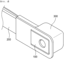
- FIG. 2 is a perspective view showing a busbar assembly according to a first preferred embodiment of the present invention
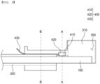
- FIG. 3 is a sectional view of the busbar assembly according to the first preferred embodiment of the present invention, cut in a vertical direction
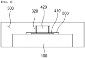
- FIG. 4 is a sectional view taken along line A-A of FIG. 3
- FIG. 5 is a sectional view taken along line B-B of FIG. 3 .
- the busbar assembly includes a busbar 100, a cover member 200, a cover cap 300, and a thermistor assembly 400.
- the busbar 100 may be made of a flat copper material, and each of opposite ends of the busbar 100 may be electrically connected to a battery module adjacent thereto.
- the cover member 200 may wrap around a part of the busbar 100 to prevent short circuit due to contact between the busbar 100 and metal components adjacent thereto.
- the cover member 200 may be located so as to wrap around a middle part of the busbar 100, excluding the ends. As described above, the cover member 200 may be made of an electrically insulative material to prevent contact between the busbar 100 and a metal adjacent thereto, and the cover member 200 may be made of an elastic material to protect the busbar 100 from external impact, as needed.
- the cover member 200 may be made of a material including at least one of silicone, rubber, polyurethane, mica, a plastic resin, glass fiber woven fabric, and a mixture of mPPO and glass fiber.
- the material for the cover member 200 is not limited thereto, as long as the state in which the cover member 200 wraps around the busbar 100 is maintained and contact between the busbar 100 and a metal material adjacent thereto is prevented, whereby insulation of the busbar 100 is maintained.
- the cover cap 300 may be located so as to wrap around each end of the busbar 100 that is not wrapped by the cover member 200 and a part of the cover member 200.
- a first receiving portion 310 which defines a predetermined space, may be formed in a part of the cover cap 300 protruding toward one side of the cover member 200, and a second receiving portion 320 may be formed between the first receiving portion 310 and the cover member 200.
- the first receiving portion 310 is a space in which a bolt and a nut may be received when the busbar 100 is connected to a battery module or the like using the bolt and the nut, whereby it is possible to maintain insulation of the bolt and the nut fastened to the busbar 100.
- the second receiving portion 320 may be formed between the first receiving portion 310 and the cover member 200, and may define a predetermined space to receive the thermistor assembly 400.
- the second receiving portion 320 may block contact between the thermistor assembly 400 received therein and a metal member adjacent thereto, e.g., a module case configured to receive a battery cell, thereby preventing short circuit.
- a recess 330 which is a space in which a wire 430 of the thermistor assembly 400 is received, may be formed at the position at which the wire 430 and the cover cap 300 are in tight contact with each other.
- the recess 330 may wrap around the wire 430 to protect the wire 430 from external impact.
- the thermistor assembly 400 which is configured to measure the temperature of the busbar 100, may include a tight-contact plate 410, a thermistor 420, and a wire 430.
- the tight-contact plate 410 may be flat, may be made of a thermally conductive and electrically insulative material, and may be located under the second receiving portion 320.
- the tight-contact plate 410 may be formed so as to have an area greater than the horizontal sectional area of the second receiving portion 320, and may support the thermistor 420 located at an upper surface thereof.
- the thermistor 420 is received in the second receiving portion 320, and may be a sensor located at the upper surface of the tight-contact plate 410 to measure the temperature of the busbar 100.
- the thermistor 420 has the advantage of measuring the temperature of the busbar 100 transmitted through the tight-contact plate 410 in real time, whereby it is possible to immediately respond to change in temperature of the busbar 100.
- the second receiving portion 320 which receives the thermistor 420, may be formed so as to have a size capable of being in tight contact with the thermistor 420, whereby it is possible to protect the thermistor 420 from external impact.
- One side of the wire 430 may be connected to the thermistor 420, and the other side of the wire may be connected to a control component, such as a battery management system (BMS).
- BMS battery management system
- the wire 430 allows a temperature measurement value and a signal of the busbar 100 measured by the thermistor 420 to be transmitted to the control member (not shown).
- An adhesive tape 500 may be formed at each of a lower surface of the tight-contact plate 410 and a lower surface of the wire 430 received in the recess 330 to fix the tight-contact plate 410 and the wire 430.
- the adhesive tape 500 may be made of a thermally conductive and electrically insulative material, e.g., an epoxy resin; however, the material for the adhesive tape 500 is not limited thereto as long as the adhesive tape 500 is thermally conductive and electrically insulative, is capable of fixing the tight-contact plate 410 and the wire 430, and is capable of transferring heat generated by the busbar 100 to the tight-contact plate 410.
- a thermally conductive and electrically insulative material e.g., an epoxy resin
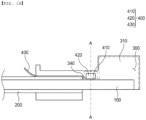
- FIG. 6 is a sectional view of a busbar assembly according to a second preferred embodiment of the present invention, cut in the vertical direction
- FIG. 7 is a sectional view taken along line A-A of FIG. 6 .
- the busbar assembly according to the second preferred embodiment of the present invention is identical to the busbar assembly according to the first embodiment described with reference to FIGs. 2 to 5 except for the size of a second receiving portion 320, and therefore a description of the same configuration will be omitted.
- the second receiving portion 320 may be formed so as to have a shape and a size such that an inner surface of the second receiving portion 320 and a thermistor 420 are spaced apart from each other so as not to be in contact with each other.
- the second receiving portion 320 has the advantage of being spaced apart from the thermistor 420 such that an empty space is defined between the second receiving portion 320 and the thermistor 420 and the empty space serves as a buffer against external impact.
- FIG. 8 is a sectional view of a busbar assembly according to a third preferred embodiment of the present invention, cut in the vertical direction
- FIG. 9 is a sectional view taken along line A-A of FIG. 8 .
- the busbar assembly according to the third preferred embodiment of the present invention is identical to the busbar assembly according to the first embodiment described with reference to FIGs. 2 to 5 except that an inclined portion 340 is formed at a cover cap 300, and therefore a description of the same configuration will be omitted.
- the cover cap 300 is provided with an inclined portion 340 inclined at a predetermined angle from a lower end of a second receiving portion 320 in a direction toward a recess 330.
- the inclined portion 340 is formed such that the angle of a bent part of a wire 430 is gentle, which has the advantage of eliminating damage to the wire 430 due to bending.
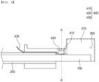
- FIG. 10 is a sectional view of a busbar assembly according to a fourth preferred embodiment of the present invention, cut in the vertical direction, and FIG. 11 is a sectional view taken along line A-A of FIG. 10 .
- the busbar assembly according to the fourth preferred embodiment of the present invention is identical to the busbar assembly according to the first embodiment described with reference to FIGs. 2 to 5 except for the size of a second receiving portion 320 and an inclined portion 340 formed at a cover cap 300, and therefore a description of the same configuration will be omitted.
- the second receiving portion 320 may be formed so as to have a size and a shape such that the second receiving portion 320 is spaced apart from a thermistor 420 received in the second receiving portion 320, and an empty space defined between the second receiving portion 320 and the thermistor 420 may serve as a buffer against external impact.
- the inclined portion 340 may be formed so as to be inclined at a predetermined angle from a lower end of the second receiving portion 320 in a direction toward a recess 330, whereby the angle of a bent part of a wire 430 extending from the lower end of the second receiving portion 320 in the direction toward the recess 330 may be gentle, which has the advantage of reducing damage to the wire 430 due to bending.
- the present invention may provide a battery pack including the busbar assembly and a device having the battery pack mounted therein.
Landscapes
- Chemical & Material Sciences (AREA)
- Chemical Kinetics & Catalysis (AREA)
- Electrochemistry (AREA)
- General Chemical & Material Sciences (AREA)
- Inorganic Chemistry (AREA)
- Engineering & Computer Science (AREA)
- Manufacturing & Machinery (AREA)
- Measuring Temperature Or Quantity Of Heat (AREA)
- Connection Of Batteries Or Terminals (AREA)
- Battery Mounting, Suspending (AREA)
- Secondary Cells (AREA)
Abstract
Description
- This application claims the benefit of priority to
Korean Patent Application No. 2022-0126180 filed on October 4, 2022 - The present invention relates to a busbar assembly configured such that the temperature of a busbar is easily measured and a battery pack including the same, and more particularly to a busbar assembly configured such that the temperature of a busbar is easily measured, wherein change in temperature of the busbar is measured and verified in real time, and a battery pack including the same.
- With recent development of alternative energies due to air pollution and energy depletion caused as the result of use of fossil fuels, demand for secondary batteries capable of storing electrical energy has increased. Secondary batteries, which are capable of being charged and discharged, are intimately used in daily life. For example, secondary batteries are used in mobile devices, electric vehicles, and hybrid electric vehicles.
- Required capacities of secondary batteries used as energy sources for various kinds of electronic devices inevitably used in modern society have increased due to an increase in usage of mobile devices, increasing complexity of the mobile devices, and development of electric vehicles. In order to satisfy demand of users, a plurality of battery cells is disposed in a small-sized device, whereas a battery module including a plurality of battery cells electrically connected to each other or a battery pack including a plurality of battery modules is used in a vehicle, etc.
- Meanwhile, in a battery pack, high current flows in a busbar, relative to the area of the busbar, due to increased output for fast charging, high capacity, and light weight, such that the importance of detecting and measuring a change in temperature of the busbar has increased.
-
FIG. 1 is a perspective view showing a conventional busbar. As shown inFIG. 1 , a conventional flexible busbar assembly includes abusbar 10 configured to electrically connect adjacent battery modules to each other and acover member 20 configured to wrap thebusbar 10. - A specific part of the conventional flexible busbar assembly may be deformed into a desired shape, for example by bending, in order to easily electrically connect battery modules provided on a complex path to each other.
- In the conventional flexible busbar assembly, however, a separate temperature measurement device configured to measure the temperature of the
busbar 10 is not provided, and even though a temperature measurement device is provided, a means configured to fix the temperature measurement device to thebusbar 10 in tight contact is not provided. - In addition, it is not easy to bring the temperature measurement device into direct contact with the
busbar 10, such that the reliability of the temperature measurement value of thebusbar 10 may be reduced. - (Patent Document 1)
Korean Patent Application Publication No. 2015-0101154 - The present invention has been made in view of the above problems, and it is an object of the present invention to provide a busbar assembly that is configured such that a temperature measurement device is fixed to a busbar in direct contact with the busbar and a battery pack including the same.
- It is another object of the present invention to provide a busbar assembly that is configured such that the temperature of a busbar is measured in real time by direct contact with the busbar, so as to improve reliability of a temperature value of the busbar, and a battery pack including the same.
- A busbar assembly according to the present invention to accomplish the above objects includes a busbar (100) made of a copper material, a cover member (200) configured to wrap around a part of the busbar (100), a cover cap (300) located so as to wrap around one side of the cover member (200) and the busbar (100) protruding from the one side of the cover member (200), and a thermistor assembly (400) positioned such that the cover cap (300) wraps around the thermistor assembly, the thermistor assembly being in tight contact with the busbar (100), wherein the cover cap (300) includes a first receiving portion (310) and a second receiving portion (320), the first receiving portion (310) located at a part of the busbar (100) protruding toward the one side of the cover member (200), and the second receiving portion (320) located between the first receiving portion (310) and the cover member (200).
- Also, in the busbar assembly according to the present invention, the cover cap (300) may be made of a material that is electrically insulative and elastic.
- Also, in the busbar assembly according to the present invention, the material may include at least one of silicone, rubber, polyurethane, mica, a plastic resin, glass fiber woven fabric, and a mixture of mPPO and glass fiber.
- Also, in the busbar assembly according to the present invention, the thermistor assembly (400) may include a tight-contact plate (410) in tight contact with the busbar (100), a thermistor (420) attached to the tight-contact plate (410), the thermistor being configured to measure temperature, and a wire (430) connected to the thermistor (420) and extending out of the cover cap (300).
- Also, in the busbar assembly according to the present invention, the thermistor (420) may be received in the second receiving portion (320).
- Also, in the busbar assembly according to the present invention, the second receiving portion (320) may be configured to have a size such that an inner surface of the second receiving portion (320) is in tight contact with the thermistor (420).
- Also, in the busbar assembly according to the present invention, the second receiving portion (320) may configured to have a shape and a size such that the inner surface of the second receiving portion (320) is spaced apart from the thermistor (420).
- Also, in the busbar assembly according to the present invention, the tight-contact plate (410) may include a material that is electrically insulative and thermally conductive.
- Also, in the busbar assembly according to the present invention, an adhesive tape (500) configured to fix the tight-contact plate (410) may be attached to a lower surface of the tight-contact plate (410).
- Also, in the busbar assembly according to the present invention, the tight-contact plate (410) may have an area greater than the horizontal sectional area of the second receiving portion (320).
- Also, in the busbar assembly according to the present invention, the cover cap (300) may include a recess (330) having a predetermined depth such that the wire (430) can be inserted into the recess.
- Also, in the busbar assembly according to the present invention, the cover cap (300) may include an inclined portion (340) inclined at a predetermined angle from a lower end of the second receiving portion (320) in a direction toward the recess (330).
- Also, in the busbar assembly according to the present invention, an adhesive tape (500) configured to fix the wire (430) may be attached to a lower surface of the wire (430).
- In addition, the present invention provides a battery pack including a busbar assembly having the aforementioned features.
- As is apparent from the above description, a busbar assembly according to the present invention has an advantage in that a cover cap is provided, whereby it is possible to easily fix a thermistor assembly when the temperature of a busbar is measured through the thermistor assembly while the insulated state of the busbar is maintained.
- In addition, the busbar assembly according to the present invention has an advantage in that a thermistor of the thermistor assembly can directly measure the temperature of the busbar, whereby the accuracy and rapidness of measurement results are improved.
-
-
FIG. 1 is a perspective view of a conventional busbar. -
FIG. 2 is a perspective view showing a busbar assembly according to a first preferred embodiment of the present invention. -
FIG. 3 is a sectional view of the busbar assembly according to the first preferred embodiment of the present invention, cut in a vertical direction. -
FIG. 4 is a sectional view taken along line A-A ofFIG. 3 . -
FIG. 5 is a sectional view taken along line B-B ofFIG. 3 . -
FIG. 6 is a sectional view of a busbar assembly according to a second preferred embodiment of the present invention, cut in the vertical direction. -
FIG. 7 is a sectional view taken along line A-A ofFIG. 6 . -
FIG. 8 is a sectional view of a busbar assembly according to a third preferred embodiment of the present invention, cut in the vertical direction. -
FIG. 9 is a sectional view taken along line A-A ofFIG. 8 . -
FIG. 10 is a sectional view of a busbar assembly according to a fourth preferred embodiment of the present invention, cut in the vertical direction. -
FIG. 11 is a sectional view taken along line A-A ofFIG. 10 . - Now, preferred embodiments of the present invention will be described in detail with reference to the accompanying drawings such that the preferred embodiments of the present invention can be easily implemented by a person having ordinary skill in the art to which the present invention pertains. In describing the principle of operation of the preferred embodiments of the present invention in detail, however, a detailed description of known functions and configurations incorporated herein will be omitted when the same may obscure the subject matter of the present invention.
- In addition, the same reference numbers will be used throughout the drawings to refer to parts that perform similar functions or operations. In the case in which one part is said to be connected to another part throughout the specification, not only may the one part be directly connected to the other part, but also, the one part may be indirectly connected to the other part via a further part. In addition, the fact that a certain element is included does not mean that other elements are excluded, but rather means that such elements may be further included unless mentioned otherwise.
- Hereinafter, a busbar assembly configured such that the temperature of a busbar is easily measured according to the present invention and a battery pack including the same will be described in detail with reference to the accompanying drawings.
-
FIG. 2 is a perspective view showing a busbar assembly according to a first preferred embodiment of the present invention,FIG. 3 is a sectional view of the busbar assembly according to the first preferred embodiment of the present invention, cut in a vertical direction,FIG. 4 is a sectional view taken along line A-A ofFIG. 3 , andFIG. 5 is a sectional view taken along line B-B ofFIG. 3 . - As shown in
FIGs. 2 to 5 , the busbar assembly according to the present disclosure includes abusbar 100, acover member 200, acover cap 300, and athermistor assembly 400. - The
busbar 100 may be made of a flat copper material, and each of opposite ends of thebusbar 100 may be electrically connected to a battery module adjacent thereto. - The
cover member 200 may wrap around a part of thebusbar 100 to prevent short circuit due to contact between thebusbar 100 and metal components adjacent thereto. - The
cover member 200 may be located so as to wrap around a middle part of thebusbar 100, excluding the ends. As described above, thecover member 200 may be made of an electrically insulative material to prevent contact between thebusbar 100 and a metal adjacent thereto, and thecover member 200 may be made of an elastic material to protect thebusbar 100 from external impact, as needed. - As an example, the
cover member 200 may be made of a material including at least one of silicone, rubber, polyurethane, mica, a plastic resin, glass fiber woven fabric, and a mixture of mPPO and glass fiber. However, the material for thecover member 200 is not limited thereto, as long as the state in which thecover member 200 wraps around thebusbar 100 is maintained and contact between thebusbar 100 and a metal material adjacent thereto is prevented, whereby insulation of thebusbar 100 is maintained. - The
cover cap 300 may be located so as to wrap around each end of thebusbar 100 that is not wrapped by thecover member 200 and a part of thecover member 200. - A
first receiving portion 310, which defines a predetermined space, may be formed in a part of thecover cap 300 protruding toward one side of thecover member 200, and asecond receiving portion 320 may be formed between the first receivingportion 310 and thecover member 200. - The
first receiving portion 310 is a space in which a bolt and a nut may be received when thebusbar 100 is connected to a battery module or the like using the bolt and the nut, whereby it is possible to maintain insulation of the bolt and the nut fastened to thebusbar 100. - The
second receiving portion 320 may be formed between the first receivingportion 310 and thecover member 200, and may define a predetermined space to receive thethermistor assembly 400. - The
second receiving portion 320 may block contact between thethermistor assembly 400 received therein and a metal member adjacent thereto, e.g., a module case configured to receive a battery cell, thereby preventing short circuit. - A
recess 330, which is a space in which awire 430 of thethermistor assembly 400 is received, may be formed at the position at which thewire 430 and thecover cap 300 are in tight contact with each other. - The
recess 330 may wrap around thewire 430 to protect thewire 430 from external impact. - Next, the
thermistor assembly 400, which is configured to measure the temperature of thebusbar 100, may include a tight-contact plate 410, athermistor 420, and awire 430. - The tight-
contact plate 410 may be flat, may be made of a thermally conductive and electrically insulative material, and may be located under thesecond receiving portion 320. - The tight-
contact plate 410 may be formed so as to have an area greater than the horizontal sectional area of thesecond receiving portion 320, and may support thethermistor 420 located at an upper surface thereof. - The
thermistor 420 is received in thesecond receiving portion 320, and may be a sensor located at the upper surface of the tight-contact plate 410 to measure the temperature of thebusbar 100. - The
thermistor 420 has the advantage of measuring the temperature of thebusbar 100 transmitted through the tight-contact plate 410 in real time, whereby it is possible to immediately respond to change in temperature of thebusbar 100. - At this time, the
second receiving portion 320, which receives thethermistor 420, may be formed so as to have a size capable of being in tight contact with thethermistor 420, whereby it is possible to protect thethermistor 420 from external impact. - One side of the
wire 430 may be connected to thethermistor 420, and the other side of the wire may be connected to a control component, such as a battery management system (BMS). - The
wire 430 allows a temperature measurement value and a signal of thebusbar 100 measured by thethermistor 420 to be transmitted to the control member (not shown). - An
adhesive tape 500 may be formed at each of a lower surface of the tight-contact plate 410 and a lower surface of thewire 430 received in therecess 330 to fix the tight-contact plate 410 and thewire 430. - The
adhesive tape 500 may be made of a thermally conductive and electrically insulative material, e.g., an epoxy resin; however, the material for theadhesive tape 500 is not limited thereto as long as theadhesive tape 500 is thermally conductive and electrically insulative, is capable of fixing the tight-contact plate 410 and thewire 430, and is capable of transferring heat generated by thebusbar 100 to the tight-contact plate 410. -
FIG. 6 is a sectional view of a busbar assembly according to a second preferred embodiment of the present invention, cut in the vertical direction, andFIG. 7 is a sectional view taken along line A-A ofFIG. 6 . - Referring to
FIGs. 6 and7 , the busbar assembly according to the second preferred embodiment of the present invention is identical to the busbar assembly according to the first embodiment described with reference toFIGs. 2 to 5 except for the size of asecond receiving portion 320, and therefore a description of the same configuration will be omitted. - In the busbar assembly according to the second embodiment of the present invention, the
second receiving portion 320 may be formed so as to have a shape and a size such that an inner surface of thesecond receiving portion 320 and athermistor 420 are spaced apart from each other so as not to be in contact with each other. - The
second receiving portion 320 according to the second embodiment has the advantage of being spaced apart from thethermistor 420 such that an empty space is defined between thesecond receiving portion 320 and thethermistor 420 and the empty space serves as a buffer against external impact. -
FIG. 8 is a sectional view of a busbar assembly according to a third preferred embodiment of the present invention, cut in the vertical direction, andFIG. 9 is a sectional view taken along line A-A ofFIG. 8 . - Referring to
FIGs. 8 and9 , the busbar assembly according to the third preferred embodiment of the present invention is identical to the busbar assembly according to the first embodiment described with reference toFIGs. 2 to 5 except that aninclined portion 340 is formed at acover cap 300, and therefore a description of the same configuration will be omitted. - In the busbar assembly according to the third embodiment, the
cover cap 300 is provided with aninclined portion 340 inclined at a predetermined angle from a lower end of asecond receiving portion 320 in a direction toward arecess 330. - The
inclined portion 340 is formed such that the angle of a bent part of awire 430 is gentle, which has the advantage of eliminating damage to thewire 430 due to bending. -
FIG. 10 is a sectional view of a busbar assembly according to a fourth preferred embodiment of the present invention, cut in the vertical direction, andFIG. 11 is a sectional view taken along line A-A ofFIG. 10 . - Referring to
FIGs. 10 and11 , the busbar assembly according to the fourth preferred embodiment of the present invention is identical to the busbar assembly according to the first embodiment described with reference toFIGs. 2 to 5 except for the size of asecond receiving portion 320 and aninclined portion 340 formed at acover cap 300, and therefore a description of the same configuration will be omitted. - In the busbar assembly according to the fourth embodiment of the present invention, the
second receiving portion 320 may be formed so as to have a size and a shape such that thesecond receiving portion 320 is spaced apart from athermistor 420 received in thesecond receiving portion 320, and an empty space defined between thesecond receiving portion 320 and thethermistor 420 may serve as a buffer against external impact. - The
inclined portion 340 may be formed so as to be inclined at a predetermined angle from a lower end of thesecond receiving portion 320 in a direction toward arecess 330, whereby the angle of a bent part of awire 430 extending from the lower end of thesecond receiving portion 320 in the direction toward therecess 330 may be gentle, which has the advantage of reducing damage to thewire 430 due to bending. - In addition, the present invention may provide a battery pack including the busbar assembly and a device having the battery pack mounted therein.
- Those skilled in the art to which the present invention pertains will appreciate that various applications and modifications are possible within the category of the present invention based on the above description.
-
- 100:
- Busbar
- 200:
- Cover member
- 300:
- Cover cap
- 310:
- First receiving portion
- 320:
- Second receiving portion
- 330:
- Recess
- 340:
- Inclined portion
- 400:
- Thermistor assembly
- 410:
- Tight-contact plate
- 420:
- Thermistor
- 430:
- Wire
- 500:
- Adhesive tape
Claims (14)
- A busbar assembly comprising:a busbar made of a copper material;a cover member configured to wrap around a part of the busbar;a cover cap located so as to wrap around one side of the cover member and the busbar protruding from the one side of the cover member; anda thermistor assembly positioned such that the cover cap wraps around the thermistor assembly, the thermistor assembly being in tight contact with the busbar, whereinthe cover cap includes a first receiving portion and a second receiving portion, the first receiving portion located at a part of the busbar protruding toward the one side of the cover member, and the second receiving portion located between the first receiving portion and the cover member.
- The busbar assembly according to claim 1, wherein the cover cap is made of a material that is electrically insulative and elastic.
- The busbar assembly according to claim 2, wherein the material includes at least one of silicone, rubber, polyurethane, mica, a plastic resin, glass fiber woven fabric, and a mixture of mPPO and glass fiber.
- The busbar assembly according to claim 1, wherein the thermistor assembly includes:a tight-contact plate in tight contact with the busbar;a thermistor attached to the tight-contact plate, the thermistor being configured to measure temperature; anda wire connected to the thermistor and extending out of the cover cap.
- The busbar assembly according to claim 4, wherein the thermistor is received in the second receiving portion.
- The busbar assembly according to claim 5, wherein the second receiving portion is configured to have a size such that an inner surface of the second receiving portion is in tight contact with the thermistor.
- The busbar assembly according to claim 5, wherein the second receiving portion is configured to have a shape and a size such that an inner surface of the second receiving portion is spaced apart from the thermistor.
- The busbar assembly according to claim 4, wherein the tight-contact plate comprises a material that is electrically insulative and thermally conductive.
- The busbar assembly according to claim 4, wherein an adhesive tape configured to fix the tight-contact plate is attached to a lower surface of the tight-contact plate.
- The busbar assembly according to claim 4, wherein the tight-contact plate has an area greater than a horizontal sectional area of the second receiving portion.
- The busbar assembly according to claim 4, wherein the cover cap includes a recess having a predetermined depth such that the wire can be inserted into the recess.
- The busbar assembly according to claim 11, wherein the cover cap includes an inclined portion inclined at a predetermined angle from a lower end of the second receiving portion in a direction toward the recess.
- The busbar assembly according to claim 10, wherein an adhesive tape configured to fix the wire is attached to a lower surface of the wire.
- A battery pack including the busbar assembly according to any one of claims 1 to 13.
Applications Claiming Priority (2)
| Application Number | Priority Date | Filing Date | Title |
|---|---|---|---|
| KR1020220126180A KR102734122B1 (en) | 2022-10-04 | 2022-10-04 | A busbar assembly that is easy to measure the temperature of the busbar and a battery pack including the same |
| PCT/KR2023/014461 WO2024076063A1 (en) | 2022-10-04 | 2023-09-22 | Bus bar assembly in which temperature measurement for bus bar is facilitated, and battery pack comprising same |
Publications (3)
| Publication Number | Publication Date |
|---|---|
| EP4462585A1 true EP4462585A1 (en) | 2024-11-13 |
| EP4462585A4 EP4462585A4 (en) | 2025-04-30 |
| EP4462585B1 EP4462585B1 (en) | 2026-03-04 |
Family
ID=90608689
Family Applications (1)
| Application Number | Title | Priority Date | Filing Date |
|---|---|---|---|
| EP23875129.1A Active EP4462585B1 (en) | 2022-10-04 | 2023-09-22 | Bus bar assembly in which temperature measurement for bus bar is facilitated, and battery pack comprising same |
Country Status (8)
| Country | Link |
|---|---|
| US (1) | US20250167407A1 (en) |
| EP (1) | EP4462585B1 (en) |
| JP (1) | JP7810340B2 (en) |
| KR (1) | KR102734122B1 (en) |
| CN (1) | CN118511391A (en) |
| CA (1) | CA3243187A1 (en) |
| MX (1) | MX2024011434A (en) |
| WO (1) | WO2024076063A1 (en) |
Family Cites Families (11)
| Publication number | Priority date | Publication date | Assignee | Title |
|---|---|---|---|---|
| KR101708367B1 (en) * | 2012-04-09 | 2017-02-20 | 삼성에스디아이 주식회사 | Battery pack |
| JP2015159024A (en) * | 2014-02-24 | 2015-09-03 | 愛三工業株式会社 | bus bar module |
| KR20150101154A (en) | 2014-02-26 | 2015-09-03 | 엘에스전선 주식회사 | Flexible bus bar |
| JP6315278B2 (en) | 2014-12-25 | 2018-04-25 | 株式会社オートネットワーク技術研究所 | Power storage module |
| DE102015002061B4 (en) | 2015-02-18 | 2023-11-16 | Audi Ag | Electrical busbar with sensor unit |
| KR101815152B1 (en) | 2016-10-06 | 2018-01-05 | (주) 래트론 | Temperature sensing apparatus for battery |
| EP3316384B1 (en) * | 2016-10-25 | 2019-02-20 | Samsung SDI Co., Ltd. | Battery module with a fixing for a temperature sensitive element |
| JP7447551B2 (en) * | 2020-03-02 | 2024-03-12 | 三菱マテリアル株式会社 | busbar module |
| CN212303849U (en) * | 2020-05-09 | 2021-01-05 | 中国第一汽车股份有限公司 | Wiring harness isolation plate and battery module |
| KR102735192B1 (en) * | 2020-11-30 | 2024-11-27 | 삼성에스디아이 주식회사 | Battery pack |
| US20220280272A1 (en) | 2021-03-08 | 2022-09-08 | Medicom Group Inc. | Dental nozzle device |
-
2022
- 2022-10-04 KR KR1020220126180A patent/KR102734122B1/en active Active
-
2023
- 2023-09-22 CN CN202380016139.2A patent/CN118511391A/en active Pending
- 2023-09-22 EP EP23875129.1A patent/EP4462585B1/en active Active
- 2023-09-22 CA CA3243187A patent/CA3243187A1/en active Pending
- 2023-09-22 MX MX2024011434A patent/MX2024011434A/en unknown
- 2023-09-22 WO PCT/KR2023/014461 patent/WO2024076063A1/en not_active Ceased
- 2023-09-22 US US18/841,576 patent/US20250167407A1/en active Pending
- 2023-09-22 JP JP2024521126A patent/JP7810340B2/en active Active
Also Published As
| Publication number | Publication date |
|---|---|
| EP4462585B1 (en) | 2026-03-04 |
| CA3243187A1 (en) | 2025-06-17 |
| MX2024011434A (en) | 2024-09-24 |
| JP2024545986A (en) | 2024-12-17 |
| EP4462585A4 (en) | 2025-04-30 |
| JP7810340B2 (en) | 2026-02-03 |
| CN118511391A (en) | 2024-08-16 |
| US20250167407A1 (en) | 2025-05-22 |
| KR102734122B1 (en) | 2024-11-25 |
| WO2024076063A1 (en) | 2024-04-11 |
| KR20240047037A (en) | 2024-04-12 |
Similar Documents
| Publication | Publication Date | Title |
|---|---|---|
| US11309590B2 (en) | Battery pack with improved assembly structure | |
| EP3316384B1 (en) | Battery module with a fixing for a temperature sensitive element | |
| KR101925934B1 (en) | Battery pack | |
| EP3694022A2 (en) | Battery module | |
| KR102152364B1 (en) | Battery pack | |
| US20120225334A1 (en) | Battery pack | |
| EP3316338B1 (en) | Battery module with a fixing for a temperature sensitive element | |
| US12199261B2 (en) | Battery module, battery pack including battery module, and vehicle including battery pack | |
| KR20160085621A (en) | Battery module | |
| KR102655770B1 (en) | Battery pack and vehicle comprising the battery pack | |
| US12489156B2 (en) | Battery module, battery pack comprising battery module, and vehicle comprising battery pack | |
| KR20230055871A (en) | Battery module with a pressure sensor for thermal runaway detection | |
| EP4462585B1 (en) | Bus bar assembly in which temperature measurement for bus bar is facilitated, and battery pack comprising same | |
| US12592421B2 (en) | Battery pack, electronic device and vehicle | |
| US12278396B2 (en) | Battery module, battery pack comprising battery module, and vehicle | |
| EP4148433A1 (en) | Current measurement device | |
| US20260031418A1 (en) | Battery module, battery pack and energy storage system | |
| CN222125300U (en) | Sampling assembly, sampling device, battery and power utilization device | |
| KR20250001866A (en) | Battery module | |
| EP4651262A1 (en) | Battery module | |
| KR102858873B1 (en) | Lithium-ion battery pack for AGV | |
| KR20250049127A (en) | Battery module | |
| KR20250049131A (en) | Battery module | |
| KR20240140853A (en) | Battery module | |
| KR20230057270A (en) | Battery system comprising cylindrical battery cells and a temperature sensor and method of installing the same |
Legal Events
| Date | Code | Title | Description |
|---|---|---|---|
| STAA | Information on the status of an ep patent application or granted ep patent |
Free format text: STATUS: THE INTERNATIONAL PUBLICATION HAS BEEN MADE |
|
| PUAI | Public reference made under article 153(3) epc to a published international application that has entered the european phase |
Free format text: ORIGINAL CODE: 0009012 |
|
| STAA | Information on the status of an ep patent application or granted ep patent |
Free format text: STATUS: REQUEST FOR EXAMINATION WAS MADE |
|
| 17P | Request for examination filed |
Effective date: 20240809 |
|
| AK | Designated contracting states |
Kind code of ref document: A1 Designated state(s): AL AT BE BG CH CY CZ DE DK EE ES FI FR GB GR HR HU IE IS IT LI LT LU LV MC ME MK MT NL NO PL PT RO RS SE SI SK SM TR |
|
| A4 | Supplementary search report drawn up and despatched |
Effective date: 20250331 |
|
| RIC1 | Information provided on ipc code assigned before grant |
Ipc: H01M 50/507 20210101ALI20250325BHEP Ipc: H01M 50/505 20210101ALI20250325BHEP Ipc: H01M 10/48 20060101ALI20250325BHEP Ipc: H01M 50/204 20210101ALI20250325BHEP Ipc: H01M 50/522 20210101ALI20250325BHEP Ipc: H01M 50/569 20210101ALI20250325BHEP Ipc: H01M 50/588 20210101ALI20250325BHEP Ipc: H01M 50/591 20210101AFI20250325BHEP |
|
| GRAP | Despatch of communication of intention to grant a patent |
Free format text: ORIGINAL CODE: EPIDOSNIGR1 |
|
| STAA | Information on the status of an ep patent application or granted ep patent |
Free format text: STATUS: GRANT OF PATENT IS INTENDED |
|
| RIC1 | Information provided on ipc code assigned before grant |
Ipc: H01M 50/591 20210101AFI20250918BHEP Ipc: H01M 50/588 20210101ALI20250918BHEP Ipc: H01M 50/569 20210101ALI20250918BHEP Ipc: H01M 50/522 20210101ALI20250918BHEP Ipc: H01M 50/204 20210101ALI20250918BHEP Ipc: H01M 10/48 20060101ALI20250918BHEP Ipc: H01M 50/505 20210101ALI20250918BHEP Ipc: H01M 50/507 20210101ALI20250918BHEP Ipc: H01M 50/524 20210101ALI20250918BHEP |
|
| DAV | Request for validation of the european patent (deleted) | ||
| DAX | Request for extension of the european patent (deleted) | ||
| INTG | Intention to grant announced |
Effective date: 20251002 |
|
| GRAS | Grant fee paid |
Free format text: ORIGINAL CODE: EPIDOSNIGR3 |
|
| GRAA | (expected) grant |
Free format text: ORIGINAL CODE: 0009210 |
|
| STAA | Information on the status of an ep patent application or granted ep patent |
Free format text: STATUS: THE PATENT HAS BEEN GRANTED |
|
| AK | Designated contracting states |
Kind code of ref document: B1 Designated state(s): AL AT BE BG CH CY CZ DE DK EE ES FI FR GB GR HR HU IE IS IT LI LT LU LV MC ME MK MT NL NO PL PT RO RS SE SI SK SM TR |
|
| REG | Reference to a national code |
Ref country code: CH Ref legal event code: F10 Free format text: ST27 STATUS EVENT CODE: U-0-0-F10-F00 (AS PROVIDED BY THE NATIONAL OFFICE) Effective date: 20260304 Ref country code: GB Ref legal event code: FG4D |
|
| REG | Reference to a national code |
Ref country code: IE Ref legal event code: FG4D |
|
| REG | Reference to a national code |
Ref country code: DE Ref legal event code: R096 Ref document number: 602023013158 Country of ref document: DE |
|
| P01 | Opt-out of the competence of the unified patent court (upc) registered |
Free format text: CASE NUMBER: UPC_APP_0006134_4462585/2026 Effective date: 20260219 |
|
| REG | Reference to a national code |
Ref country code: NL Ref legal event code: FP |