EP4462019A1 - Combined combustion burner and combustion apparatus including same - Google Patents
Combined combustion burner and combustion apparatus including same Download PDFInfo
- Publication number
- EP4462019A1 EP4462019A1 EP24174678.3A EP24174678A EP4462019A1 EP 4462019 A1 EP4462019 A1 EP 4462019A1 EP 24174678 A EP24174678 A EP 24174678A EP 4462019 A1 EP4462019 A1 EP 4462019A1
- Authority
- EP
- European Patent Office
- Prior art keywords
- fuel
- spray
- spray nozzle
- combustion burner
- tube
- Prior art date
- Legal status (The legal status is an assumption and is not a legal conclusion. Google has not performed a legal analysis and makes no representation as to the accuracy of the status listed.)
- Granted
Links
Images

Classifications
-
- F—MECHANICAL ENGINEERING; LIGHTING; HEATING; WEAPONS; BLASTING
- F23—COMBUSTION APPARATUS; COMBUSTION PROCESSES
- F23D—BURNERS
- F23D1/00—Burners for combustion of pulverulent fuel
-
- F—MECHANICAL ENGINEERING; LIGHTING; HEATING; WEAPONS; BLASTING
- F23—COMBUSTION APPARATUS; COMBUSTION PROCESSES
- F23D—BURNERS
- F23D17/00—Burners for combustion simultaneously or alternately of gaseous or liquid or pulverulent fuel
- F23D17/007—Burners for combustion simultaneously or alternately of gaseous or liquid or pulverulent fuel liquid or pulverulent fuel
-
- F—MECHANICAL ENGINEERING; LIGHTING; HEATING; WEAPONS; BLASTING
- F23—COMBUSTION APPARATUS; COMBUSTION PROCESSES
- F23D—BURNERS
- F23D17/00—Burners for combustion simultaneously or alternately of gaseous or liquid or pulverulent fuel
-
- F—MECHANICAL ENGINEERING; LIGHTING; HEATING; WEAPONS; BLASTING
- F23—COMBUSTION APPARATUS; COMBUSTION PROCESSES
- F23C—METHODS OR APPARATUS FOR COMBUSTION USING FLUID FUEL OR SOLID FUEL SUSPENDED IN A CARRIER GAS OR AIR
- F23C1/00—Combustion apparatus specially adapted for combustion of two or more kinds of fuel simultaneously or alternately, at least one kind of fuel being either a fluid fuel or a solid fuel suspended in a carrier gas or air
- F23C1/10—Combustion apparatus specially adapted for combustion of two or more kinds of fuel simultaneously or alternately, at least one kind of fuel being either a fluid fuel or a solid fuel suspended in a carrier gas or air liquid and pulverulent fuel
-
- F—MECHANICAL ENGINEERING; LIGHTING; HEATING; WEAPONS; BLASTING
- F23—COMBUSTION APPARATUS; COMBUSTION PROCESSES
- F23C—METHODS OR APPARATUS FOR COMBUSTION USING FLUID FUEL OR SOLID FUEL SUSPENDED IN A CARRIER GAS OR AIR
- F23C1/00—Combustion apparatus specially adapted for combustion of two or more kinds of fuel simultaneously or alternately, at least one kind of fuel being either a fluid fuel or a solid fuel suspended in a carrier gas or air
- F23C1/12—Combustion apparatus specially adapted for combustion of two or more kinds of fuel simultaneously or alternately, at least one kind of fuel being either a fluid fuel or a solid fuel suspended in a carrier gas or air gaseous and pulverulent fuel
-
- F—MECHANICAL ENGINEERING; LIGHTING; HEATING; WEAPONS; BLASTING
- F23—COMBUSTION APPARATUS; COMBUSTION PROCESSES
- F23C—METHODS OR APPARATUS FOR COMBUSTION USING FLUID FUEL OR SOLID FUEL SUSPENDED IN A CARRIER GAS OR AIR
- F23C5/00—Disposition of burners with respect to the combustion chamber or to one another; Mounting of burners in combustion apparatus
- F23C5/08—Disposition of burners
- F23C5/10—Disposition of burners to obtain a flame ring
- F23C5/12—Disposition of burners to obtain a flame ring for pulverulent fuel
-
- F—MECHANICAL ENGINEERING; LIGHTING; HEATING; WEAPONS; BLASTING
- F23—COMBUSTION APPARATUS; COMBUSTION PROCESSES
- F23C—METHODS OR APPARATUS FOR COMBUSTION USING FLUID FUEL OR SOLID FUEL SUSPENDED IN A CARRIER GAS OR AIR
- F23C6/00—Combustion apparatus characterised by the combination of two or more combustion chambers or combustion zones, e.g. for staged combustion
- F23C6/04—Combustion apparatus characterised by the combination of two or more combustion chambers or combustion zones, e.g. for staged combustion in series connection
- F23C6/045—Combustion apparatus characterised by the combination of two or more combustion chambers or combustion zones, e.g. for staged combustion in series connection with staged combustion in a single enclosure
- F23C6/047—Combustion apparatus characterised by the combination of two or more combustion chambers or combustion zones, e.g. for staged combustion in series connection with staged combustion in a single enclosure with fuel supply in stages
-
- F—MECHANICAL ENGINEERING; LIGHTING; HEATING; WEAPONS; BLASTING
- F23—COMBUSTION APPARATUS; COMBUSTION PROCESSES
- F23C—METHODS OR APPARATUS FOR COMBUSTION USING FLUID FUEL OR SOLID FUEL SUSPENDED IN A CARRIER GAS OR AIR
- F23C7/00—Combustion apparatus characterised by arrangements for air supply
-
- F—MECHANICAL ENGINEERING; LIGHTING; HEATING; WEAPONS; BLASTING
- F23—COMBUSTION APPARATUS; COMBUSTION PROCESSES
- F23D—BURNERS
- F23D11/00—Burners using a direct spraying action of liquid droplets or vaporised liquid into the combustion space
- F23D11/10—Burners using a direct spraying action of liquid droplets or vaporised liquid into the combustion space the spraying being induced by a gaseous medium, e.g. water vapour
- F23D11/101—Burners using a direct spraying action of liquid droplets or vaporised liquid into the combustion space the spraying being induced by a gaseous medium, e.g. water vapour medium and fuel meeting before the burner outlet
- F23D11/102—Burners using a direct spraying action of liquid droplets or vaporised liquid into the combustion space the spraying being induced by a gaseous medium, e.g. water vapour medium and fuel meeting before the burner outlet in an internal mixing chamber
-
- F—MECHANICAL ENGINEERING; LIGHTING; HEATING; WEAPONS; BLASTING
- F23—COMBUSTION APPARATUS; COMBUSTION PROCESSES
- F23D—BURNERS
- F23D11/00—Burners using a direct spraying action of liquid droplets or vaporised liquid into the combustion space
- F23D11/36—Details
-
- F—MECHANICAL ENGINEERING; LIGHTING; HEATING; WEAPONS; BLASTING
- F23—COMBUSTION APPARATUS; COMBUSTION PROCESSES
- F23D—BURNERS
- F23D14/00—Burners for combustion of a gas, e.g. of a gas stored under pressure as a liquid
- F23D14/02—Premix gas burners, i.e. in which gaseous fuel is mixed with combustion air upstream of the combustion zone
-
- F—MECHANICAL ENGINEERING; LIGHTING; HEATING; WEAPONS; BLASTING
- F23—COMBUSTION APPARATUS; COMBUSTION PROCESSES
- F23D—BURNERS
- F23D14/00—Burners for combustion of a gas, e.g. of a gas stored under pressure as a liquid
- F23D14/46—Details
-
- F—MECHANICAL ENGINEERING; LIGHTING; HEATING; WEAPONS; BLASTING
- F23—COMBUSTION APPARATUS; COMBUSTION PROCESSES
- F23D—BURNERS
- F23D17/00—Burners for combustion simultaneously or alternately of gaseous or liquid or pulverulent fuel
- F23D17/005—Burners for combustion simultaneously or alternately of gaseous or liquid or pulverulent fuel gaseous or pulverulent fuel
-
- F—MECHANICAL ENGINEERING; LIGHTING; HEATING; WEAPONS; BLASTING
- F23—COMBUSTION APPARATUS; COMBUSTION PROCESSES
- F23C—METHODS OR APPARATUS FOR COMBUSTION USING FLUID FUEL OR SOLID FUEL SUSPENDED IN A CARRIER GAS OR AIR
- F23C2201/00—Staged combustion
- F23C2201/30—Staged fuel supply
- F23C2201/301—Staged fuel supply with different fuels in stages
-
- F—MECHANICAL ENGINEERING; LIGHTING; HEATING; WEAPONS; BLASTING
- F23—COMBUSTION APPARATUS; COMBUSTION PROCESSES
- F23C—METHODS OR APPARATUS FOR COMBUSTION USING FLUID FUEL OR SOLID FUEL SUSPENDED IN A CARRIER GAS OR AIR
- F23C2900/00—Special features of, or arrangements for combustion apparatus using fluid fuels or solid fuels suspended in air; Combustion processes therefor
- F23C2900/06041—Staged supply of oxidant
-
- F—MECHANICAL ENGINEERING; LIGHTING; HEATING; WEAPONS; BLASTING
- F23—COMBUSTION APPARATUS; COMBUSTION PROCESSES
- F23D—BURNERS
- F23D2201/00—Burners adapted for particulate solid or pulverulent fuels
-
- F—MECHANICAL ENGINEERING; LIGHTING; HEATING; WEAPONS; BLASTING
- F23—COMBUSTION APPARATUS; COMBUSTION PROCESSES
- F23D—BURNERS
- F23D2204/00—Burners adapted for simultaneous or alternative combustion having more than one fuel supply
- F23D2204/10—Burners adapted for simultaneous or alternative combustion having more than one fuel supply gaseous and liquid fuel
-
- F—MECHANICAL ENGINEERING; LIGHTING; HEATING; WEAPONS; BLASTING
- F23—COMBUSTION APPARATUS; COMBUSTION PROCESSES
- F23D—BURNERS
- F23D2204/00—Burners adapted for simultaneous or alternative combustion having more than one fuel supply
- F23D2204/20—Burners adapted for simultaneous or alternative combustion having more than one fuel supply gaseous and pulverulent fuel
-
- F—MECHANICAL ENGINEERING; LIGHTING; HEATING; WEAPONS; BLASTING
- F23—COMBUSTION APPARATUS; COMBUSTION PROCESSES
- F23D—BURNERS
- F23D2204/00—Burners adapted for simultaneous or alternative combustion having more than one fuel supply
- F23D2204/30—Burners adapted for simultaneous or alternative combustion having more than one fuel supply liquid and pulverulent fuel
-
- F—MECHANICAL ENGINEERING; LIGHTING; HEATING; WEAPONS; BLASTING
- F23—COMBUSTION APPARATUS; COMBUSTION PROCESSES
- F23D—BURNERS
- F23D2214/00—Cooling
-
- F—MECHANICAL ENGINEERING; LIGHTING; HEATING; WEAPONS; BLASTING
- F23—COMBUSTION APPARATUS; COMBUSTION PROCESSES
- F23N—REGULATING OR CONTROLLING COMBUSTION
- F23N2237/00—Controlling
- F23N2237/08—Controlling two or more different types of fuel simultaneously
Definitions
- Exemplary embodiments relate to a combined combustion burner using solid fuel, and relate to a combustion apparatus including the combined combustion burner.
- a thermal power generation plant refers to a plant that burns fossil fuels and generates steam required for a power plant or industrial use.
- steam is generated by thermal energy obtained by burning pulverized coal that is solid fuel, and power is generated by operating a turbine and a generator.
- a plurality of nozzles is provided inside the coal thermal power generation plant, and the plurality of nozzles provided on a side wall of a burner is configured to spray pulverized coal and combustion air to an inner side of the burner.
- the nozzles not only spray pulverized coal and mixed air, but also spray secondary air and tertiary air to the outside of premixed air, thereby forming a recirculation region inside a furnace.
- a recirculation area is an area in which a reduction reaction is performed because air is sparse, and the generation of nitrogen oxides is suppressed in the recirculation area.
- a combined combustion burner including: a center tube forming a center passage configured to supply cooling air; a fuel tube surrounding the center tube and forming a fuel passage through which premixed fuel mixed with solid fuel and primary air is sprayed; a secondary tube surrounding the fuel tube and forming a secondary passage through which secondary air is sprayed; and an additional spray nozzle inserted inside the center tube and configured to spray auxiliary fuel containing ammonia.
- the additional spray nozzle may be configured to spray the auxiliary fuel to an inner side of a space where the secondary air is sprayed.
- the additional spray nozzle may be configured to spray the auxiliary fuel to an inner side of a space where the premixed fuel is sprayed.
- an oil nozzle may be provided configured to spray liquid fuel.
- the oil nozzle may be mounted in the center passage.
- the additional spray nozzle may be configured to spray the auxiliary fuel to an outside of a space where the liquid fuel is sprayed.
- the additional spray nozzle may be mounted such that ammonia is sprayed to a recirculation area.
- a discharge portion inclined with respect to a longitudinal direction of the additional spray nozzle may be formed on the additional spray nozzle.
- a spray port through which the auxiliary fuel is sprayed may be formed on the additional spray nozzle.
- the spray port may be formed such that a normal direction of the spray port is inclined with respect to a radial direction of the additional spray nozzle.
- One part of an outer circumferential surface of the discharge portion may extend in a straight line.
- the other part of the outer circumferential surface of the discharge portion may be curved in an arc shape.
- the additional spray nozzle may be mounted such that the additional spray nozzle is capable of being rotated with respect to a central axis of the additional spray nozzle.
- a rotation control member configured to rotate the additional spray nozzle may be connected to the additional spray nozzle.
- An auxiliary spray member configured to spray ammonia fuel containing ammonia in a gaseous state into the fuel passage may be mounted in the fuel passage.
- the auxiliary spray member may be formed in a ring shape.
- the auxiliary spray member may include a plurality of spray holes configured to spray the ammonia fuel.
- the auxiliary spray member may include a distribution passage that extends along a circumferential direction of the auxiliary spray member.
- the auxiliary spray member may be fixed to an outer circumferential surface of the center tube.
- An ammonia supply tube connected to the distribution passage may be mounted in the center tube.
- the spray holes may be inclined toward an outside of a radial direction of the auxiliary spray member.
- the spray holes may be formed of long holes.
- the spray holes may be formed such that a major axis direction of the spray holes is inclined with respect to the radial direction.
- the spray holes may be formed such that an inner diameter of each of the spray holes is gradually decreased toward a downstream side of each of the spray holes.
- a combustion apparatus including: a furnace forming a combustion space; and a burner including a plurality of burners mounted in the furnace, wherein the burner includes: a center tube forming a center passage configured to supply cooling air; a fuel tube surrounding the center tube and forming a fuel passage through which premixed fuel mixed with solid fuel and primary air is sprayed; a secondary tube surrounding the fuel tube and forming a secondary passage through which secondary air is sprayed; and an additional spray nozzle inserted inside the center tube and configured to spray auxiliary fuel containing ammonia.
- An oil nozzle configured to spray liquid fuel may be mounted in the center passage, and the additional spray nozzle may be configured to spray the auxiliary fuel to an outside of a space where the liquid fuel is sprayed and may be configured to spray the auxiliary fuel to an inside of a space where the premixed fuel is sprayed.
- the burner according to an aspect of the present disclosure includes the additional spray nozzle, so that the generation of carbon dioxide may be reduced and the generation of nitrogen oxides that is generated during combustion of ammonia may be reduced.
- ammonia fuel is sprayed between solid fuel and liquid fuel, so that a flame may be stably maintained without harming the stability of the flame.
- the additional spray nozzle and the auxiliary spray member are provided, a combustion amount of ammonia fuel is increased, so that a generation amount of carbon dioxide may be further reduced.
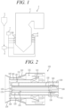
- FIG. 1 is a view schematically illustrating a configuration of a combustion apparatus according to the first embodiment of the present disclosure.
- a combustion apparatus 2 may be the combustion apparatus 2 that generates steam by burning fuel in a thermal power plant and so on.
- the combustion apparatus 2 may include a furnace 3 that provides a combustion space and a space in which combustion gas is moved, a plurality of burners 100 mounted in the furnace 3, a hopper 5 in which solid fuel is accommodated, a pulverizer 6 configured to pulverize the solid fuel, and a boiler 4 configured to generate steam by heat exchange.
- Solid fuel is stored in the hopper 5, and the solid fuel may be formed of consist of pulverized coal, biomass, and so on.
- the pulverizer 6 is configured to finely pulverize solid fuel supplied from the hopper 5.
- the furnace 3 provides the combustion space, and the plurality of burners 100 may be mounted in the furnace 3.
- the burners 100 may be disposed such that the burners 100 are spaced apart from each other and disposed along a circumferential direction of the furnace 3.
- an additional supply tube 8 that additionally supplies air may be mounted on an upper portion of the burner 100.
- the boiler 4 is configured to generate steam by exchanging heat with combustion gas that is generated from the burner 100.
- An ammonia supply portion 7 that supplies fuel containing ammonia may be connected to the burners 100.
- FIG. 2 is a cross-sectional view illustrating a burner according to the first embodiment of the present disclosure
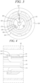
- FIG. 3 is a front view illustrating the burner according to the first embodiment of the present disclosure
- FIG. 4 is a view enlarging and illustrating an A1 in FIG. 2
- FIG. 5 is a view illustrating an additional spray nozzle and a center tube viewed from the front
- FIG. 6 is a cross-sectional view illustrating the additional spray nozzle according to the first embodiment of the present disclosure.
- the burner 100 forms a flame by burning liquid fuel, solid fuel, and auxiliary fuel.
- the burner 100 may include a center tube 130, a fuel tube 120, a secondary tube 140, a tertiary tube 150, an additional spray nozzle 170, and an oil nozzle 136.
- the center tube 130 is formed in a cylindrical shape, and a center passage 135 that supplies cooling air is formed inside the center tube 130.
- the oil nozzle 136 configured to spray liquid fuel may be mounted on a center of the center tube 130 in a radial direction. Liquid fuel may be supplied to the oil nozzle 136, and the liquid fuel may be formed of heavy fuel oil and so on.
- the fuel tube 120 is mounted such that the fuel tube 120 surrounds the center tube 130, and a fuel passage 125 in which premixed fuel formed by mixing solid fuel and primary air is moved is formed inside the fuel tube 120.
- solid fuel may be formed of coal or biomass.
- a protrusion portion 123 for maintaining the flame may be formed on a downstream side of the fuel tube 120.
- a first flared tube portion 126 is formed on a distal end of the fuel tube 120. An outer diameter of the first flared tube portion 126 is gradually increased toward the distal end of the fuel tube 120, but an inner diameter of the first flared tube portion 126 is formed uniformly.
- the secondary tube 140 is mounted such that the secondary tube 140 surrounds the fuel tube 120, and forms a secondary passage 145 through which secondary air SA1 (see FIG. 7 ) is sprayed.
- the secondary air SA1 is sprayed to an outside of the premixed fuel and provides oxygen, and is discharged while surrounding the flame.
- a second flared tube portion 146 is formed on a distal end of the secondary tube 140, and the second flared tube portion 146 is formed such that an outer diameter and an inner diameter of the second flared tube portion 146 are gradually increased toward the distal end of the secondary tube 140.
- a swirler vane 141 forming a swirl flow may be mounted in the secondary tube 140.
- the tertiary tube 150 is mounted such that the tertiary tube 150 surrounds the secondary tube 140, and forms a tertiary passage 155 through which tertiary air TA1 (see FIG. 7 ) is sprayed.
- the tertiary air TA1 is sprayed to the outside of the premixed fuel and provides oxygen, and is discharged while surrounding the flame.
- a third flared tube portion 156 is formed on a distal end of the tertiary tube 150, and the third flared tube portion 156 is formed such that an outer diameter and an inner diameter of the third flared tube portion 156 are gradually increased toward the distal end of the tertiary tube 150.
- a swirler vane 151 forming a swirl flow may be mounted in the tertiary tube 150.
- an auxiliary spray member 180 is mounted in the fuel passage 125.
- the auxiliary spray member 180 sprays ammonia fuel containing ammonia in a gaseous state into the fuel passage 125. Accordingly, in the fuel passage 125, pulverized coal, ammonia, and the primary air may be moved together.
- the auxiliary spray member 180 may include a plurality of spray holes 181 configured to spray ammonia fuel, and may include a distribution passage 182 that extends along a circumferential direction of the auxiliary spray member 180.
- the auxiliary spray member 180 is formed in a ring shape, and is fixed to an outer circumferential surface of the center tube 130.
- an ammonia supply tube 186 configured to supply ammonia to the auxiliary spray member 180 may be mounted in the center tube 130.
- the ammonia supply tube 186 may be connected to the distribution passage 182 of the auxiliary spray member 180 by passing through the center tube 130 from an upstream side of the center tube 130. As such, when the ammonia supply tube 186 is mounted in the center tube 130, ammonia fuel may be easily supplied without interfering with the movement of the premixed fuel.
- the distribution passage 182 is formed inside the auxiliary spray member 180, and is formed such that the distribution passage 182 extends along the circumferential direction of the auxiliary spray member 180.
- the plurality of spray holes 181 is formed in the auxiliary spray member 180, and the spray holes 181 may extend frontward from the distribution passage 182 and may obliquely extend toward the outside in a radial direction.
- the spray holes 181 are formed of long holes, and may be formed such that a major axis direction of the spray holes 181 is inclined at a third inclination angle A13 with respect to the radial direction.
- the third inclination angle A13 may be 5 degrees to 60 degrees. Accordingly, ammonia sprayed from the auxiliary spray member 180 may be mixed with the primary air and solid fuel while forming a swirl.
- the spray hole 181 may be formed such that an inner diameter is gradually decreased toward a downstream side thereof. Accordingly, pulverized coal may be prevented from being introduced inside the spray hole 181.
- the additional spray nozzle 170 configured to spray auxiliary fuel AM1 containing ammonia is mounted in the center passage 135.
- a plurality of additional spray nozzles 170 may be mounted in the center passage 135, and the additional spray nozzles 170 may be disposed such that the additional spray nozzles are disposed on the outside of the oil nozzle 136 and are spaced apart from each other along a circumferential direction.
- the auxiliary fuel AM1 may include at least 50% ammonia, in some aspects.
- the auxiliary fuel AM1 may include from about 80% ammonia to about 100% ammonia, in other aspects.
- the auxiliary fuel AM1 may include ammonia in a gaseous form, but the present disclosure is not limited thereto, and the auxiliary fuel AM1 may include ammonia in a liquid form or in a powder form.
- the additional spray nozzle 170 is formed such that the additional spray nozzle 170 extends along a longitudinal direction of the center passage 135, and a nozzle cap 176 having a spray port 171 is mounted on the additional spray nozzle 170.
- a discharge portion 175 having an internal flow path inclined with respect to a longitudinal direction of the additional spray nozzle 170 may be formed on an end portion of the additional spray nozzle 170.
- the discharge portion 175 may be formed on the nozzle cap 176.
- a longitudinal end portion of the additional spray nozzle 170 is positioned such that the longitudinal end portion of the additional spray nozzle 170 protrudes to the same extent as a longitudinal end portion of the center tube 130 or protrudes further forward than the longitudinal end portion of the center tube 130, and is positioned further rear than longitudinal end portions of the fuel tube 120 and the secondary tube 140. Accordingly, damage to the additional spray nozzle 170 by heat may be minimized.
- a part 176a of an outer circumferential surface of the discharge portion 175 may extend in a straight line, and the other part 176b may be curved in an arc shape. Accordingly, the part formed in the straight line may guide the discharge of cooling air, and auxiliary fuel may be sprayed without interrupting the flow of air.
- the discharge portion 175 may be inclined at a first inclination angle A11 with respect to the longitudinal direction of the additional spray nozzle 170, and the discharge portion 175 may be formed such that the discharge portion 175 is inclined outward in the radial direction.
- the first inclination angle A11 may be 45 degrees.
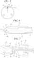
- a discharge portion 271a may be inclined at zero degrees with respect to a longitudinal direction of an additional spray nozzle 271 as illustrated in FIG. 8
- a discharge portion 272a may be formed such that a first inclination angle A21 of the discharge portion 272a inclined with respect to a longitudinal direction of an additional spray nozzle 272 may be 15 degrees as illustrated in FIG. 9
- a discharge portion 273a may be formed such that a first inclination angle A22 of the discharge portion 273a inclined with respect to a longitudinal direction of an additional spray nozzle 273 may be 30 degrees as illustrated in FIG.
- a discharge portion 274a may be formed such that a first inclination angle A23 of the discharge portion 274a inclined with respect to a longitudinal direction of an additional spray nozzle 274 may be 60 degrees as illustrated in FIG. 11 .
- the first inclination angle may be set to zero degrees to 60 degrees.
- the spray port 171 through which auxiliary fuel is sprayed is formed on the additional spray nozzle 170, and the spray port 171 may be formed such that a normal direction of the spray port 171 is inclined at a second inclination angle A12 with respect to the radial direction.
- the additional spray nozzle 170 may be mounted such that the additional spray nozzle 170 is capable of being rotated with respect to a central axis of the additional spray nozzle 170, and the second inclination angle A12 may be adjusted according to the rotation of the additional spray nozzle 170.
- the second inclination angle A12 may be set to zero degrees to 45 degrees.
- a recirculation area RA1 in which a reduction reaction is performed since air is rarefied is formed inside the tertiary air TA1 and the secondary air SA1, and the additional spray nozzle 170 may spray the auxiliary fuel AM1 to the recirculation area RA1.
- the auxiliary fuel AM1 is sprayed into the recirculation area RA1
- ammonia does not meet with air and is not oxidized, and ammonia is pyrolyzed into nitrogen and hydrogen, so that the generation of nitrogen oxides may be significantly reduced.
- the additional spray nozzle 170 is configured to spray the auxiliary fuel AM1 into an inside of a space where the secondary air SA1 is sprayed. Accordingly, the auxiliary fuel AM1 does not interrupt the flow of the secondary air SA1, and the auxiliary fuel AM1 may be prevent from being dispersed by the secondary air SA1.
- the additional spray nozzle 170 is configured to spray the auxiliary fuel AM1 into an inside of a space where premixed fuel is sprayed. Accordingly, the auxiliary fuel AM1 containing ammonia is sprayed to an inner side of a flame formed by solid fuel such as pulverized coal and so on, thereby being capable of preventing oxidation of ammonia.
- the additional spray nozzle 170 is configured to spray the auxiliary fuel AM1 into an outside of a space where liquid fuel is sprayed. Accordingly, a flame is maintained by the liquid fuel, and ammonia is sprayed into the recirculation area RA1 formed inside the maintained flame, so that the auxiliary fuel AM1 may participate in combustion while the flame is maintained in a stable state.
- FIG. 12 is a cross-sectional view illustrating the burner according to a second embodiment of the present disclosure.
- a burner 200 according to the present embodiment has the same structure as the burner according to the first embodiment, except for a rotation control member 210, a duplicate description of the same configuration is omitted.
- the additional spray nozzle 170 may be mounted such that the additional spray nozzle 170 is capable of being rotated with respect to the central axis of the additional spray nozzle 170.
- the rotation control member 210 configured to rotate the additional spray nozzle 170 is mounted on the additional spray nozzle 170.
- a spray direction of mixed fuel containing ammonia may be controlled according to the rotation of the additional spray nozzle 170.
- the rotation control member 210 may include an actuator or a motor.
- the additional spray nozzle 170 is rotated and ammonia is sprayed according to a combustion situation, so that a flame may be stabilized and the generation of nitrogen oxides may be significantly reduced.
Landscapes
- Engineering & Computer Science (AREA)
- Chemical & Material Sciences (AREA)
- Combustion & Propulsion (AREA)
- Mechanical Engineering (AREA)
- General Engineering & Computer Science (AREA)
Abstract
Description
- The present application claims priority to
Korean Patent Application No. 10-2023-0059255, filed May 8, 2023 - Exemplary embodiments relate to a combined combustion burner using solid fuel, and relate to a combustion apparatus including the combined combustion burner.
- Generally, a thermal power generation plant refers to a plant that burns fossil fuels and generates steam required for a power plant or industrial use. In a coal thermal power generation plant, steam is generated by thermal energy obtained by burning pulverized coal that is solid fuel, and power is generated by operating a turbine and a generator.
- A plurality of nozzles is provided inside the coal thermal power generation plant, and the plurality of nozzles provided on a side wall of a burner is configured to spray pulverized coal and combustion air to an inner side of the burner. The nozzles not only spray pulverized coal and mixed air, but also spray secondary air and tertiary air to the outside of premixed air, thereby forming a recirculation region inside a furnace. Such a recirculation area is an area in which a reduction reaction is performed because air is sparse, and the generation of nitrogen oxides is suppressed in the recirculation area.
- However, in a conventional combustion apparatus that burns fossil fuel, there is a problem of high carbon dioxide emissions. In order to solve this problem, a technology of supplying ammonia as fuel is being developed. However, ammonia contains a large amount of nitrogen, and there is a problem that a large amount of nitrogen oxides is generated when ammonia is combusted.
- It is an object of the present disclosure to provide a combined combustion burner and a combustion apparatus including the combined combustion burner capable of reducing the generation of carbon dioxide and the generation of nitrogen oxides.
- Additional aspects will be set forth in part in the description which follows and, in part, will become apparent from the description, or may be learned by practice of the exemplary embodiments.
- The object is solved by the features of the independent claims. Preferred embodiments are given in the dependent claims.
- According to an aspect of an exemplary embodiment, there is provided a combined combustion burner including: a center tube forming a center passage configured to supply cooling air; a fuel tube surrounding the center tube and forming a fuel passage through which premixed fuel mixed with solid fuel and primary air is sprayed; a secondary tube surrounding the fuel tube and forming a secondary passage through which secondary air is sprayed; and an additional spray nozzle inserted inside the center tube and configured to spray auxiliary fuel containing ammonia.
- The additional spray nozzle may be configured to spray the auxiliary fuel to an inner side of a space where the secondary air is sprayed.
- The additional spray nozzle may be configured to spray the auxiliary fuel to an inner side of a space where the premixed fuel is sprayed.
- In one or more embodiments, an oil nozzle may be provided configured to spray liquid fuel.
- In one or more embodiments, the oil nozzle may be mounted in the center passage.
- In one or more embodiments, the additional spray nozzle may be configured to spray the auxiliary fuel to an outside of a space where the liquid fuel is sprayed.
- The additional spray nozzle may be mounted such that ammonia is sprayed to a recirculation area.
- A discharge portion inclined with respect to a longitudinal direction of the additional spray nozzle may be formed on the additional spray nozzle.
- A spray port through which the auxiliary fuel is sprayed may be formed on the additional spray nozzle.
- In one or more embodiments, the spray port may be formed such that a normal direction of the spray port is inclined with respect to a radial direction of the additional spray nozzle.
- One part of an outer circumferential surface of the discharge portion may extend in a straight line.
- In one or more embodiments, the other part of the outer circumferential surface of the discharge portion may be curved in an arc shape.
- The additional spray nozzle may be mounted such that the additional spray nozzle is capable of being rotated with respect to a central axis of the additional spray nozzle.
- A rotation control member configured to rotate the additional spray nozzle may be connected to the additional spray nozzle.
- An auxiliary spray member configured to spray ammonia fuel containing ammonia in a gaseous state into the fuel passage may be mounted in the fuel passage.
- The auxiliary spray member may be formed in a ring shape.
- The auxiliary spray member may include a plurality of spray holes configured to spray the ammonia fuel.
- The auxiliary spray member may include a distribution passage that extends along a circumferential direction of the auxiliary spray member.
- The auxiliary spray member may be fixed to an outer circumferential surface of the center tube.
- An ammonia supply tube connected to the distribution passage may be mounted in the center tube.
- The spray holes may be inclined toward an outside of a radial direction of the auxiliary spray member.
- The spray holes may be formed of long holes.
- The spray holes may be formed such that a major axis direction of the spray holes is inclined with respect to the radial direction.
- The spray holes may be formed such that an inner diameter of each of the spray holes is gradually decreased toward a downstream side of each of the spray holes.
- According to an aspect of another exemplary embodiment, there is provided a combustion apparatus including: a furnace forming a combustion space; and a burner including a plurality of burners mounted in the furnace, wherein the burner includes: a center tube forming a center passage configured to supply cooling air; a fuel tube surrounding the center tube and forming a fuel passage through which premixed fuel mixed with solid fuel and primary air is sprayed; a secondary tube surrounding the fuel tube and forming a secondary passage through which secondary air is sprayed; and an additional spray nozzle inserted inside the center tube and configured to spray auxiliary fuel containing ammonia.
- An oil nozzle configured to spray liquid fuel may be mounted in the center passage, and the additional spray nozzle may be configured to spray the auxiliary fuel to an outside of a space where the liquid fuel is sprayed and may be configured to spray the auxiliary fuel to an inside of a space where the premixed fuel is sprayed.
- As described above, the burner according to an aspect of the present disclosure includes the additional spray nozzle, so that the generation of carbon dioxide may be reduced and the generation of nitrogen oxides that is generated during combustion of ammonia may be reduced. In addition, ammonia fuel is sprayed between solid fuel and liquid fuel, so that a flame may be stably maintained without harming the stability of the flame. In addition, since the additional spray nozzle and the auxiliary spray member are provided, a combustion amount of ammonia fuel is increased, so that a generation amount of carbon dioxide may be further reduced.
- It is to be understood that both the foregoing general description and the following detailed description of exemplary embodiments are exemplary and explanatory and are intended to provide further explanation of the disclosure as claimed.
- The above and other objectives, features, and other advantages of the present disclosure will be more clearly understood from the following detailed description when taken in conjunction with the accompanying drawings, in which:
-
FIG. 1 is a view schematically illustrating a configuration of a combustion apparatus according to a first embodiment of the present disclosure; -
FIG. 2 is a cross-sectional view illustrating a burner of the first embodiment of the disclosure; -
FIG. 3 is a front view illustrating the burner of the first embodiment of the present disclosure; -
FIG. 4 is an enlarged view illustrating area A1 inFIG. 2 ; -
FIG. 5 is a view illustrating an additional spray nozzle and a center tube viewed from the front; -
FIG. 6 is a cross-sectional view illustrating the additional spray nozzle of the first embodiment of the present disclosure; -
FIG. 7 is a view illustrating a configuration of the burner of the first embodiment of the disclosure; -
FIG. 8 is a cross-sectional view illustrating the additional spray nozzle according to a first modification example of the first embodiment of the present disclosure; -
FIG. 9 is a cross-sectional view illustrating the additional spray nozzle according to a second modification example of the first embodiment of the present disclosure; -
FIG. 10 is a cross-sectional view illustrating the additional spray nozzle according to a third modification example of the first embodiment of the present disclosure; -
FIG. 11 is a cross-sectional view illustrating the additional spray nozzle according to a fourth modification example of the first embodiment of the present disclosure; and -
FIG. 12 is a cross-sectional view illustrating the burner of a second embodiment of the disclosure. - Various modifications and different embodiments will be described below in detail with reference to the accompanying drawings so that those skilled in the art can easily carry out the present disclosure. It should be understood, however, that the present disclosure is not intended to be limited to the specific embodiments, but the present disclosure includes all modifications, equivalents or replacements that fall within the scope of the disclosure as defined in the following claims.
- The terminology used herein is for the purpose of describing specific embodiments only and is not intended to limit the scope of the present disclosure. As used herein, the singular forms "a", "an", and "the" are intended to include the plural forms as well, unless the context clearly indicates otherwise. In the present disclosure, terms such as "comprises", "includes", or "have/has" should be construed as designating that there are such features, integers, steps, operations, components, parts, and/or combinations thereof, not to exclude the presence or possibility of adding of one or more of other features, integers, steps, operations, components, parts, and/or combinations thereof.
- Hereinafter, exemplary embodiments will be described below in detail with reference to the accompanying drawings. It should be noted that like reference numerals refer to like parts throughout various drawings and exemplary embodiments. In certain embodiments, a detailed description of functions and configurations well known in the art may be omitted to avoid obscuring appreciation of the present disclosure by those skilled in the art. For the same reason, some components may be exaggerated, omitted, or schematically illustrated in the accompanying drawings.
- Hereinafter, a combustion apparatus according to a first embodiment of the present disclosure will be described.
-
FIG. 1 is a view schematically illustrating a configuration of a combustion apparatus according to the first embodiment of the present disclosure. - Referring to
FIG. 1 , acombustion apparatus 2 according to the present embodiment may be thecombustion apparatus 2 that generates steam by burning fuel in a thermal power plant and so on. - The
combustion apparatus 2 may include a furnace 3 that provides a combustion space and a space in which combustion gas is moved, a plurality ofburners 100 mounted in the furnace 3, ahopper 5 in which solid fuel is accommodated, a pulverizer 6 configured to pulverize the solid fuel, and a boiler 4 configured to generate steam by heat exchange. - Solid fuel is stored in the
hopper 5, and the solid fuel may be formed of consist of pulverized coal, biomass, and so on. The pulverizer 6 is configured to finely pulverize solid fuel supplied from thehopper 5. The furnace 3 provides the combustion space, and the plurality ofburners 100 may be mounted in the furnace 3. - The
burners 100 may be disposed such that theburners 100 are spaced apart from each other and disposed along a circumferential direction of the furnace 3. In addition, in the furnace 3, an additional supply tube 8 that additionally supplies air may be mounted on an upper portion of theburner 100. The boiler 4 is configured to generate steam by exchanging heat with combustion gas that is generated from theburner 100. Anammonia supply portion 7 that supplies fuel containing ammonia may be connected to theburners 100. -
FIG. 2 is a cross-sectional view illustrating a burner according to the first embodiment of the present disclosure,FIG. 3 is a front view illustrating the burner according to the first embodiment of the present disclosure,FIG. 4 is a view enlarging and illustrating an A1 inFIG. 2 ,FIG. 5 is a view illustrating an additional spray nozzle and a center tube viewed from the front, andFIG. 6 is a cross-sectional view illustrating the additional spray nozzle according to the first embodiment of the present disclosure. - Referring to
FIGS. 2 to 6 , theburner 100 forms a flame by burning liquid fuel, solid fuel, and auxiliary fuel. Theburner 100 may include acenter tube 130, afuel tube 120, asecondary tube 140, atertiary tube 150, anadditional spray nozzle 170, and anoil nozzle 136. - The
center tube 130 is formed in a cylindrical shape, and acenter passage 135 that supplies cooling air is formed inside thecenter tube 130. In addition, theoil nozzle 136 configured to spray liquid fuel may be mounted on a center of thecenter tube 130 in a radial direction. Liquid fuel may be supplied to theoil nozzle 136, and the liquid fuel may be formed of heavy fuel oil and so on. - The
fuel tube 120 is mounted such that thefuel tube 120 surrounds thecenter tube 130, and afuel passage 125 in which premixed fuel formed by mixing solid fuel and primary air is moved is formed inside thefuel tube 120. Here, solid fuel may be formed of coal or biomass. Aprotrusion portion 123 for maintaining the flame may be formed on a downstream side of thefuel tube 120. In addition, a first flaredtube portion 126 is formed on a distal end of thefuel tube 120. An outer diameter of the first flaredtube portion 126 is gradually increased toward the distal end of thefuel tube 120, but an inner diameter of the first flaredtube portion 126 is formed uniformly. - The
secondary tube 140 is mounted such that thesecondary tube 140 surrounds thefuel tube 120, and forms asecondary passage 145 through which secondary air SA1 (seeFIG. 7 ) is sprayed. The secondary air SA1 is sprayed to an outside of the premixed fuel and provides oxygen, and is discharged while surrounding the flame. A second flaredtube portion 146 is formed on a distal end of thesecondary tube 140, and the second flaredtube portion 146 is formed such that an outer diameter and an inner diameter of the second flaredtube portion 146 are gradually increased toward the distal end of thesecondary tube 140. Aswirler vane 141 forming a swirl flow may be mounted in thesecondary tube 140. - The
tertiary tube 150 is mounted such that thetertiary tube 150 surrounds thesecondary tube 140, and forms atertiary passage 155 through which tertiary air TA1 (seeFIG. 7 ) is sprayed. The tertiary air TA1 is sprayed to the outside of the premixed fuel and provides oxygen, and is discharged while surrounding the flame. A third flaredtube portion 156 is formed on a distal end of thetertiary tube 150, and the third flaredtube portion 156 is formed such that an outer diameter and an inner diameter of the third flaredtube portion 156 are gradually increased toward the distal end of thetertiary tube 150. Aswirler vane 151 forming a swirl flow may be mounted in thetertiary tube 150. - Meanwhile, as illustrated in
FIG. 3 and FIG. 4 , anauxiliary spray member 180 is mounted in thefuel passage 125. Theauxiliary spray member 180 sprays ammonia fuel containing ammonia in a gaseous state into thefuel passage 125. Accordingly, in thefuel passage 125, pulverized coal, ammonia, and the primary air may be moved together. - The
auxiliary spray member 180 may include a plurality ofspray holes 181 configured to spray ammonia fuel, and may include adistribution passage 182 that extends along a circumferential direction of theauxiliary spray member 180. Theauxiliary spray member 180 is formed in a ring shape, and is fixed to an outer circumferential surface of thecenter tube 130. Meanwhile, anammonia supply tube 186 configured to supply ammonia to theauxiliary spray member 180 may be mounted in thecenter tube 130. Theammonia supply tube 186 may be connected to thedistribution passage 182 of theauxiliary spray member 180 by passing through thecenter tube 130 from an upstream side of thecenter tube 130. As such, when theammonia supply tube 186 is mounted in thecenter tube 130, ammonia fuel may be easily supplied without interfering with the movement of the premixed fuel. - The
distribution passage 182 is formed inside theauxiliary spray member 180, and is formed such that thedistribution passage 182 extends along the circumferential direction of theauxiliary spray member 180. The plurality of spray holes 181 is formed in theauxiliary spray member 180, and the spray holes 181 may extend frontward from thedistribution passage 182 and may obliquely extend toward the outside in a radial direction. In addition, the spray holes 181 are formed of long holes, and may be formed such that a major axis direction of the spray holes 181 is inclined at a third inclination angle A13 with respect to the radial direction. Here, the third inclination angle A13 may be 5 degrees to 60 degrees. Accordingly, ammonia sprayed from theauxiliary spray member 180 may be mixed with the primary air and solid fuel while forming a swirl. - In addition, the
spray hole 181 may be formed such that an inner diameter is gradually decreased toward a downstream side thereof. Accordingly, pulverized coal may be prevented from being introduced inside thespray hole 181. - In addition, as illustrated in
FIG. 5 and FIG. 6 , theadditional spray nozzle 170 configured to spray auxiliary fuel AM1 containing ammonia is mounted in thecenter passage 135. A plurality ofadditional spray nozzles 170 may be mounted in thecenter passage 135, and theadditional spray nozzles 170 may be disposed such that the additional spray nozzles are disposed on the outside of theoil nozzle 136 and are spaced apart from each other along a circumferential direction. The auxiliary fuel AM1 may include at least 50% ammonia, in some aspects. The auxiliary fuel AM1 may include from about 80% ammonia to about 100% ammonia, in other aspects. The auxiliary fuel AM1 may include ammonia in a gaseous form, but the present disclosure is not limited thereto, and the auxiliary fuel AM1 may include ammonia in a liquid form or in a powder form. - The
additional spray nozzle 170 is formed such that theadditional spray nozzle 170 extends along a longitudinal direction of thecenter passage 135, and anozzle cap 176 having aspray port 171 is mounted on theadditional spray nozzle 170. In addition, adischarge portion 175 having an internal flow path inclined with respect to a longitudinal direction of theadditional spray nozzle 170 may be formed on an end portion of theadditional spray nozzle 170. Thedischarge portion 175 may be formed on thenozzle cap 176. - A longitudinal end portion of the
additional spray nozzle 170 is positioned such that the longitudinal end portion of theadditional spray nozzle 170 protrudes to the same extent as a longitudinal end portion of thecenter tube 130 or protrudes further forward than the longitudinal end portion of thecenter tube 130, and is positioned further rear than longitudinal end portions of thefuel tube 120 and thesecondary tube 140. Accordingly, damage to theadditional spray nozzle 170 by heat may be minimized. - A
part 176a of an outer circumferential surface of thedischarge portion 175 may extend in a straight line, and theother part 176b may be curved in an arc shape. Accordingly, the part formed in the straight line may guide the discharge of cooling air, and auxiliary fuel may be sprayed without interrupting the flow of air. - The
discharge portion 175 may be inclined at a first inclination angle A11 with respect to the longitudinal direction of theadditional spray nozzle 170, and thedischarge portion 175 may be formed such that thedischarge portion 175 is inclined outward in the radial direction. - Here, the first inclination angle A11 may be 45 degrees. However, the present disclosure is not limited thereto. Furthermore, a
discharge portion 271a may be inclined at zero degrees with respect to a longitudinal direction of anadditional spray nozzle 271 as illustrated inFIG. 8 , adischarge portion 272a may be formed such that a first inclination angle A21 of thedischarge portion 272a inclined with respect to a longitudinal direction of anadditional spray nozzle 272 may be 15 degrees as illustrated inFIG. 9 , adischarge portion 273a may be formed such that a first inclination angle A22 of thedischarge portion 273a inclined with respect to a longitudinal direction of anadditional spray nozzle 273 may be 30 degrees as illustrated inFIG. 10 , and adischarge portion 274a may be formed such that a first inclination angle A23 of thedischarge portion 274a inclined with respect to a longitudinal direction of anadditional spray nozzle 274 may be 60 degrees as illustrated inFIG. 11 . As such, the first inclination angle may be set to zero degrees to 60 degrees. - In addition, the
spray port 171 through which auxiliary fuel is sprayed is formed on theadditional spray nozzle 170, and thespray port 171 may be formed such that a normal direction of thespray port 171 is inclined at a second inclination angle A12 with respect to the radial direction. Theadditional spray nozzle 170 may be mounted such that theadditional spray nozzle 170 is capable of being rotated with respect to a central axis of theadditional spray nozzle 170, and the second inclination angle A12 may be adjusted according to the rotation of theadditional spray nozzle 170. The second inclination angle A12 may be set to zero degrees to 45 degrees. - As illustrated in
FIG. 7 , a recirculation area RA1 in which a reduction reaction is performed since air is rarefied is formed inside the tertiary air TA1 and the secondary air SA1, and theadditional spray nozzle 170 may spray the auxiliary fuel AM1 to the recirculation area RA1. When the auxiliary fuel AM1 is sprayed into the recirculation area RA1, ammonia does not meet with air and is not oxidized, and ammonia is pyrolyzed into nitrogen and hydrogen, so that the generation of nitrogen oxides may be significantly reduced. - The
additional spray nozzle 170 is configured to spray the auxiliary fuel AM1 into an inside of a space where the secondary air SA1 is sprayed. Accordingly, the auxiliary fuel AM1 does not interrupt the flow of the secondary air SA1, and the auxiliary fuel AM1 may be prevent from being dispersed by the secondary air SA1. - In addition, the
additional spray nozzle 170 is configured to spray the auxiliary fuel AM1 into an inside of a space where premixed fuel is sprayed. Accordingly, the auxiliary fuel AM1 containing ammonia is sprayed to an inner side of a flame formed by solid fuel such as pulverized coal and so on, thereby being capable of preventing oxidation of ammonia. - Meanwhile, the
additional spray nozzle 170 is configured to spray the auxiliary fuel AM1 into an outside of a space where liquid fuel is sprayed. Accordingly, a flame is maintained by the liquid fuel, and ammonia is sprayed into the recirculation area RA1 formed inside the maintained flame, so that the auxiliary fuel AM1 may participate in combustion while the flame is maintained in a stable state. - As described above, according to the present embodiment, since fuel containing ammonia is sprayed by the
additional spray nozzle 170 and theauxiliary spray member 180, the generation of carbon dioxide may be reduced. In addition, since ammonia is sprayed into a reduction area, the generation of nitrogen oxides due to combustion of ammonia may be reduced. - Hereinafter, the burner according to a second embodiment of the present disclosure will be described.
-
FIG. 12 is a cross-sectional view illustrating the burner according to a second embodiment of the present disclosure. - Referring to
FIG. 12 , since aburner 200 according to the present embodiment has the same structure as the burner according to the first embodiment, except for arotation control member 210, a duplicate description of the same configuration is omitted. - The
additional spray nozzle 170 may be mounted such that theadditional spray nozzle 170 is capable of being rotated with respect to the central axis of theadditional spray nozzle 170. Therotation control member 210 configured to rotate theadditional spray nozzle 170 is mounted on theadditional spray nozzle 170. A spray direction of mixed fuel containing ammonia may be controlled according to the rotation of theadditional spray nozzle 170. Therotation control member 210 may include an actuator or a motor. - As described above, according to the present embodiment, since the
rotation control member 210 is mounted, theadditional spray nozzle 170 is rotated and ammonia is sprayed according to a combustion situation, so that a flame may be stabilized and the generation of nitrogen oxides may be significantly reduced. - While one or more exemplary embodiments have been described with reference to the accompanying drawings, it will be apparent to those skilled in the art that various variations and modifications may be made by adding, changing, or removing components without departing from the scope of the present disclosure as defined in the appended claims, and these variations and modifications fall within the scope of the present disclosure as defined in the appended claims. In addition, it is noted that any one feature of an embodiment of the present disclosure described in the specification may be applied to another embodiment of the present disclosure.
Claims (15)
- A combined combustion burner (100, 200) comprising:a center tube (130) forming a center passage (135) configured to supply cooling air;a fuel tube (120) surrounding the center tube (130) and forming a fuel passage (125) through which premixed fuel mixed with solid fuel and primary air is sprayed;a secondary tube (140) surrounding the fuel tube (120) and forming a secondary passage (145) through which secondary air (SA1) is sprayed; andan additional spray nozzle (170, 271, 272, 273, 274) inserted inside the center tube (130) and configured to spray auxiliary fuel (AM1) containing ammonia.
- The combined combustion burner (100, 200) of claim 1, wherein the additional spray nozzle (170, 271, 272, 273, 274) is configured to spray the auxiliary fuel (AM1) to an inner side of a space where the secondary air (SA1) is sprayed or to an inner side of a space where the premixed fuel is sprayed.
- The combined combustion burner (100, 200) of any one of the preceding claims, further comprising an oil nozzle (136) mounted in the center passage (135) and configured to spray liquid fuel.
- The combined combustion burner (100, 200) of claim 3, wherein the additional spray nozzle (170, 271, 272, 273, 274) is configured to spray the auxiliary fuel (AM1) to an outside of a space where the liquid fuel is sprayed.
- The combined combustion burner (100, 200) of any one of the preceding claims, wherein the additional spray nozzle (170, 271, 272, 273, 274) is mounted such that ammonia is sprayed to a recirculation area (RA1).
- The combined combustion burner (100, 200) of any one of the preceding claims, wherein a discharge portion (175, 271a, 272a, 273a, 274a) inclined with respect to a longitudinal direction of the additional spray nozzle (170, 271, 272, 273, 274) is formed on the additional spray nozzle (170, 271, 272, 273, 274).
- The combined combustion burner (100, 200) of any one of the preceding claims, wherein a spray port (171) through which the auxiliary fuel (AM1) is sprayed is formed on the additional spray nozzle (170, 271, 272, 273, 274), preferably the spray port (171) is formed such that a normal direction of the spray port (171) is inclined with respect to a radial direction of the additional spray nozzle (170, 271, 272, 273, 274).
- The combined combustion burner (100, 200) of claim 6 or 7, wherein one part of an outer circumferential surface of the discharge portion (175, 271a, 272a, 273a, 274a) extends in a straight line, and the other part of the outer circumferential surface of the discharge portion (175, 271a, 272a, 273a, 274a) is curved in an arc shape.
- The combined combustion burner (100, 200) of any one of the preceding claims, wherein the additional spray nozzle (170, 271, 272, 273, 274) is mounted such that the additional spray nozzle (170, 271, 272, 273, 274) is capable of being rotated with respect to a central axis of the additional spray nozzle (170, 271, 272, 273, 274).
- The combined combustion burner (100, 200) of any one of the preceding claims, further comprising a rotation control member configured to rotate the additional spray nozzle (170, 271, 272, 273, 274), preferably the rotation control member is connected to the additional spray nozzle (170, 271, 272, 273, 274).
- The combined combustion burner (100, 200) of any one of the preceding claims, further comprising an auxiliary spray member (180) mounted in the fuel passage (125) and configured to spray ammonia fuel containing ammonia in a gaseous state into the fuel passage (125).
- The combined combustion burner (100, 200) of claim 11, wherein the auxiliary spray member (180) is formed in a ring shape, comprises a plurality of spray holes (186) configured to spray the ammonia fuel, and comprises a distribution passage that extends along a circumferential direction of the auxiliary spray member (180).
- The combined combustion burner (100, 200) of claim 11 or 12, wherein the auxiliary spray member (180) is fixed to an outer circumferential surface of the center tube (130).
- The combined combustion burner (100, 200) of claim 12 or 13, wherein an ammonia supply tube (186) connected to the distribution passage is mounted in the center tube (130).
- A combustion apparatus (2) comprising:a furnace (3) forming a combustion space; anda burner (100, 200) as claimed in any one of the preceding claims and comprising a plurality of burners (100, 200) mounted in the furnace (3).
Applications Claiming Priority (1)
| Application Number | Priority Date | Filing Date | Title |
|---|---|---|---|
| KR1020230059255A KR102821855B1 (en) | 2023-05-08 | 2023-05-08 | Combined combustion burner, combustor including the same |
Publications (2)
| Publication Number | Publication Date |
|---|---|
| EP4462019A1 true EP4462019A1 (en) | 2024-11-13 |
| EP4462019B1 EP4462019B1 (en) | 2026-03-04 |
Family
ID=91030204
Family Applications (1)
| Application Number | Title | Priority Date | Filing Date |
|---|---|---|---|
| EP24174678.3A Active EP4462019B1 (en) | 2023-05-08 | 2024-05-07 | Combined combustion burners and combustion apparatus including same |
Country Status (4)
| Country | Link |
|---|---|
| US (1) | US20240377061A1 (en) |
| EP (1) | EP4462019B1 (en) |
| KR (1) | KR102821855B1 (en) |
| CN (1) | CN118912510A (en) |
Citations (4)
| Publication number | Priority date | Publication date | Assignee | Title |
|---|---|---|---|---|
| CN114877334A (en) * | 2022-04-28 | 2022-08-09 | 西安交通大学 | Ammonia gas and pulverized coal dual-fuel burner for industrial pulverized coal boiler |
| CN218379390U (en) * | 2022-04-22 | 2023-01-24 | 东方电气集团东方锅炉股份有限公司 | Cyclone burner for mixed combustion of ammonia and coal |
| WO2023062876A1 (en) * | 2021-10-14 | 2023-04-20 | 株式会社Ihi | Combustion device and boiler |
| KR20230059255A (en) | 2021-10-26 | 2023-05-03 | 주식회사 씨앤에스아이티엠 | Method and system for collecting food waste based on blockchain |
Family Cites Families (8)
| Publication number | Priority date | Publication date | Assignee | Title |
|---|---|---|---|---|
| US5813845A (en) * | 1996-12-04 | 1998-09-29 | Saint-Gobain/Norton Industrial Ceramics Corporation | Curved silicon-carbide based burner nozzle for use with gaseous fuel flames |
| JP3009370B2 (en) * | 1997-03-07 | 2000-02-14 | 株式会社日立製作所 | Pulverized coal burner, pulverized coal boiler and pulverized coal combustion method |
| FR2816037B1 (en) * | 2000-11-02 | 2003-01-03 | Air Liquide | BURNER AND METHOD FOR PARTIAL OXIDATION OF A GAS STREAM COMPRISING HYDROGEN SULFIDE AND AMMONIA |
| KR101757973B1 (en) * | 2015-05-15 | 2017-07-13 | 김형석 | Nozzle apparatus for preventing from clogging and method using the same |
| JP7081258B2 (en) * | 2018-03-27 | 2022-06-07 | 住友大阪セメント株式会社 | Fuel combustion device |
| JP6813533B2 (en) * | 2018-05-22 | 2021-01-13 | 三菱パワー株式会社 | Burner and combustion equipment |
| JP7498654B2 (en) | 2020-12-09 | 2024-06-12 | 川崎重工業株式会社 | Burner, its control method, and combustion furnace |
| CN113623653B (en) * | 2021-08-12 | 2022-07-26 | 清华大学 | Atmosphere-adjustable axial-cutting multistage cyclone ammonia-doped burner |
-
2023
- 2023-05-08 KR KR1020230059255A patent/KR102821855B1/en active Active
-
2024
- 2024-04-24 CN CN202410495265.7A patent/CN118912510A/en active Pending
- 2024-05-02 US US18/653,630 patent/US20240377061A1/en active Pending
- 2024-05-07 EP EP24174678.3A patent/EP4462019B1/en active Active
Patent Citations (4)
| Publication number | Priority date | Publication date | Assignee | Title |
|---|---|---|---|---|
| WO2023062876A1 (en) * | 2021-10-14 | 2023-04-20 | 株式会社Ihi | Combustion device and boiler |
| KR20230059255A (en) | 2021-10-26 | 2023-05-03 | 주식회사 씨앤에스아이티엠 | Method and system for collecting food waste based on blockchain |
| CN218379390U (en) * | 2022-04-22 | 2023-01-24 | 东方电气集团东方锅炉股份有限公司 | Cyclone burner for mixed combustion of ammonia and coal |
| CN114877334A (en) * | 2022-04-28 | 2022-08-09 | 西安交通大学 | Ammonia gas and pulverized coal dual-fuel burner for industrial pulverized coal boiler |
Also Published As
| Publication number | Publication date |
|---|---|
| CN118912510A (en) | 2024-11-08 |
| KR102821855B1 (en) | 2025-06-16 |
| KR20240162326A (en) | 2024-11-15 |
| US20240377061A1 (en) | 2024-11-14 |
| EP4462019B1 (en) | 2026-03-04 |
Similar Documents
| Publication | Publication Date | Title |
|---|---|---|
| EP3620719B1 (en) | Gas turbine combustor | |
| CN111059574B (en) | Swirl cup type dual-fuel air atomizing nozzle structure | |
| EP2065645B1 (en) | Burner and gas turbine combustor | |
| EP1736705A1 (en) | Combustion apparatus and combustion method | |
| JP7498654B2 (en) | Burner, its control method, and combustion furnace | |
| US20080193886A1 (en) | Combustion Apparatus | |
| KR20000064285A (en) | Combustion burner and combustion apparatus with the burner | |
| US20250052419A1 (en) | Burner and combustion furnace | |
| JP2005106305A (en) | Nozzle for fuel combustion and fuel supply method for gas turbine combustor | |
| US20240230085A9 (en) | Combustion device and boiler | |
| EP4462019B1 (en) | Combined combustion burners and combustion apparatus including same | |
| JP7816486B2 (en) | Combustion equipment | |
| US20250052420A1 (en) | Burner and combustion furnace | |
| CN116878027B (en) | Gas turbine combustion chamber nozzle structure and working method thereof | |
| JP2000074372A (en) | Burner | |
| KR102893433B1 (en) | Combined combustion burner, combustor including the same | |
| JP2024168313A (en) | Burners and furnaces | |
| JP3004263B1 (en) | Oil-fired low NOx burner | |
| WO2025033170A1 (en) | Burner and combustion furnace | |
| JP2025101202A (en) | Gas burner | |
| CN117346180A (en) | Combustion chamber, gas turbine and gas turbine system |
Legal Events
| Date | Code | Title | Description |
|---|---|---|---|
| PUAI | Public reference made under article 153(3) epc to a published international application that has entered the european phase |
Free format text: ORIGINAL CODE: 0009012 |
|
| STAA | Information on the status of an ep patent application or granted ep patent |
Free format text: STATUS: REQUEST FOR EXAMINATION WAS MADE |
|
| 17P | Request for examination filed |
Effective date: 20240507 |
|
| AK | Designated contracting states |
Kind code of ref document: A1 Designated state(s): AL AT BE BG CH CY CZ DE DK EE ES FI FR GB GR HR HU IE IS IT LI LT LU LV MC ME MK MT NL NO PL PT RO RS SE SI SK SM TR |
|
| GRAP | Despatch of communication of intention to grant a patent |
Free format text: ORIGINAL CODE: EPIDOSNIGR1 |
|
| STAA | Information on the status of an ep patent application or granted ep patent |
Free format text: STATUS: GRANT OF PATENT IS INTENDED |
|
| INTG | Intention to grant announced |
Effective date: 20251014 |
|
| GRAS | Grant fee paid |
Free format text: ORIGINAL CODE: EPIDOSNIGR3 |
|
| GRAA | (expected) grant |
Free format text: ORIGINAL CODE: 0009210 |
|
| STAA | Information on the status of an ep patent application or granted ep patent |
Free format text: STATUS: THE PATENT HAS BEEN GRANTED |
|
| AK | Designated contracting states |
Kind code of ref document: B1 Designated state(s): AL AT BE BG CH CY CZ DE DK EE ES FI FR GB GR HR HU IE IS IT LI LT LU LV MC ME MK MT NL NO PL PT RO RS SE SI SK SM TR |
|
| REG | Reference to a national code |
Ref country code: CH Ref legal event code: F10 Free format text: ST27 STATUS EVENT CODE: U-0-0-F10-F00 (AS PROVIDED BY THE NATIONAL OFFICE) Effective date: 20260304 Ref country code: GB Ref legal event code: FG4D |
|
| REG | Reference to a national code |
Ref country code: CH Ref legal event code: R17 Free format text: ST27 STATUS EVENT CODE: U-0-0-R10-R17 (AS PROVIDED BY THE NATIONAL OFFICE) Effective date: 20260318 |
|
| REG | Reference to a national code |
Ref country code: IE Ref legal event code: FG4D |
|
| REG | Reference to a national code |
Ref country code: DE Ref legal event code: R096 Ref document number: 602024002925 Country of ref document: DE |