EP4462002A2 - Connector and method for connecting pipes for transporting fluids - Google Patents
Connector and method for connecting pipes for transporting fluids Download PDFInfo
- Publication number
- EP4462002A2 EP4462002A2 EP24202802.5A EP24202802A EP4462002A2 EP 4462002 A2 EP4462002 A2 EP 4462002A2 EP 24202802 A EP24202802 A EP 24202802A EP 4462002 A2 EP4462002 A2 EP 4462002A2
- Authority
- EP
- European Patent Office
- Prior art keywords
- tubular sleeve
- main axis
- end insert
- connector
- tubular
- Prior art date
- Legal status (The legal status is an assumption and is not a legal conclusion. Google has not performed a legal analysis and makes no representation as to the accuracy of the status listed.)
- Granted
Links
Images


Classifications
-
- F—MECHANICAL ENGINEERING; LIGHTING; HEATING; WEAPONS; BLASTING
- F16—ENGINEERING ELEMENTS AND UNITS; GENERAL MEASURES FOR PRODUCING AND MAINTAINING EFFECTIVE FUNCTIONING OF MACHINES OR INSTALLATIONS; THERMAL INSULATION IN GENERAL
- F16L—PIPES; JOINTS OR FITTINGS FOR PIPES; SUPPORTS FOR PIPES, CABLES OR PROTECTIVE TUBING; MEANS FOR THERMAL INSULATION IN GENERAL
- F16L37/00—Couplings of the quick-acting type
- F16L37/08—Couplings of the quick-acting type in which the connection between abutting or axially overlapping ends is maintained by locking members
- F16L37/084—Couplings of the quick-acting type in which the connection between abutting or axially overlapping ends is maintained by locking members combined with automatic locking
- F16L37/091—Couplings of the quick-acting type in which the connection between abutting or axially overlapping ends is maintained by locking members combined with automatic locking by means of a ring provided with teeth or fingers
- F16L37/0915—Couplings of the quick-acting type in which the connection between abutting or axially overlapping ends is maintained by locking members combined with automatic locking by means of a ring provided with teeth or fingers with a separate member for releasing the coupling
-
- F—MECHANICAL ENGINEERING; LIGHTING; HEATING; WEAPONS; BLASTING
- F16—ENGINEERING ELEMENTS AND UNITS; GENERAL MEASURES FOR PRODUCING AND MAINTAINING EFFECTIVE FUNCTIONING OF MACHINES OR INSTALLATIONS; THERMAL INSULATION IN GENERAL
- F16L—PIPES; JOINTS OR FITTINGS FOR PIPES; SUPPORTS FOR PIPES, CABLES OR PROTECTIVE TUBING; MEANS FOR THERMAL INSULATION IN GENERAL
- F16L33/00—Arrangements for connecting hoses to rigid members; Rigid hose-connectors, i.e. single members engaging both hoses
- F16L33/02—Hose-clips
- F16L33/035—Hose-clips fixed by means of teeth or hooks
-
- F—MECHANICAL ENGINEERING; LIGHTING; HEATING; WEAPONS; BLASTING
- F16—ENGINEERING ELEMENTS AND UNITS; GENERAL MEASURES FOR PRODUCING AND MAINTAINING EFFECTIVE FUNCTIONING OF MACHINES OR INSTALLATIONS; THERMAL INSULATION IN GENERAL
- F16L—PIPES; JOINTS OR FITTINGS FOR PIPES; SUPPORTS FOR PIPES, CABLES OR PROTECTIVE TUBING; MEANS FOR THERMAL INSULATION IN GENERAL
- F16L33/00—Arrangements for connecting hoses to rigid members; Rigid hose-connectors, i.e. single members engaging both hoses
- F16L33/18—Arrangements for connecting hoses to rigid members; Rigid hose-connectors, i.e. single members engaging both hoses characterised by the use of additional sealing means
Definitions
- the present invention concerns a connector for connecting pipes for transporting fluids.
- the present invention concerns a method for connecting pipes for transporting fluids.
- quick attachment connectors of the push-fit type are known for connecting hoses, particularly used in the hydraulic circuits of household electrical appliances, such as for example ovens, steam machines and coffee machines.
- the connectors of known type generally comprise a tubular casing, which extends around a main axis, and a sleeve, which is configured to be fitted around a respective pipe for transporting fluids and to be inserted by pressure within the tubular casing.
- Said connectors are characterised by a quick assembly since it is only necessary to exert pressure on the sleeve along the main axis for engaging and disengaging the sleeve to/from the respective tubular casing.
- the portions to be connected of said pipes are sometimes difficult to access, often requiring the disassembly of some parts of the household electrical appliance or of the device in order to access the portions of the pipes to be connected or disconnected.
- the connector can accidentally disengage from the pipes to which it is connected, prejudicing the integrity of the hydraulic circuit in which it is incorporated.
- An object of the present invention is to manufacture a connector for connecting pipes for transporting fluids which mitigates the drawbacks of the prior art.
- a connector for connecting pipes for transporting fluids comprising:
- the end insert comprises an inner surface provided with an inner shoulder; the tubular sleeve comprising an engaging portion, which is configured to interfere with the inner shoulder so as to snap engage/disengage with the end insert.
- reference numeral 1 indicates, as a whole, a connector for connecting ends of two fluid transport pipes 2 ( Figure 3 ).
- the connector 1 can also be used for connecting one end of a transport pipe 2 ( Figure 3 ) to a further hydraulic element, such as for example a pump or a valve or a tank.
- the connector 1 is particularly applicable to hydraulic circuits of household electrical appliances, such as for example ovens, steam machines and coffee machines.
- the connector 1 comprises a tubular casing 3, which extends around a main axis A; an end insert 4, which can be snap coupled to one end of the tubular casing 3; a tubular sleeve 5, which is configured to be fitted around a respective fluid transport pipe 2 ( Figure 3 ) and to cooperate with the end insert 4 such that a relative rotation around the main axis A of the tubular sleeve 5 within the end insert 4 results in a relative displacement of the tubular sleeve 5 with respect to the end insert 4 in a direction substantially parallel to the main axis A; and a clamping element 6 ( Figures 2 and 3 ), which is housed within the tubular casing 3 and is configured to retain the respective transport pipe 2.
- tubular casing 3, the end insert 4 and the tubular sleeve 5 are made of respective polymeric materials.
- the tubular casing 3 comprises an end 7; an inner shoulder 8; an inner shoulder 9 placed between the end 7 and the inner shoulder 8 at a distance from the inner shoulder 8 along the main axis A; and a narrowing 10 configured to provide an abutment surface for one end of each transport pipe 2 ( Figure 3 ) so as to clamp the sliding of each transport pipe 2 ( Figure 3 ) in a direction substantially parallel to the main axis A when said transport pipe 2 ( Figure 3 ) is inserted within of the tubular casing 3.
- the connector 1 comprises an annular spacer 11, which is placed on the inner shoulder 9 and is shaped to support the clamping element 6.
- the clamping element 6 comprises a toothed washer 12 provided with a plurality of flexible teeth 13 facing each other.
- each flexible tooth 13 is configured to deflect when said flexible tooth 13 enters into contact with the tubular sleeve 5 during the insertion of the tubular sleeve 5 within the tubular casing 3.
- the connector 1 comprises an annular sealing element 14, preferably made of a polymeric material, which is housed within the tubular casing 3 at a distance from the clamping element 6 and is configured to interfere with the fluid transport pipe 2 ( Figure 3 ).
- the annular sealing element 14 is an O-ring.
- O-ring means a rubber ring used as mechanical gasket.
- the O-rings are designed to be inserted in suitable housings and to be compressed during the assembly of two or more parts, thus creating a sealing gasket.
- the annular sealing element 14 is supported by the inner shoulder 8. In this manner, the annular sealing element 14 is placed at such a distance from the clamping element 6 to allow the deflection of each flexible tooth 13 without said flexible tooth 13 entering into contact with the annular sealing element 14 during the insertion of the tubular sleeve 5 within the tubular casing 3.
- the tubular casing 3 comprises a plurality of engaging elements 15, each of which is placed on the outer surface of the tubular casing 3 at the end 7 and is provided with a chamfered portion 16. More specifically, the tubular casing 3 comprises four engaging elements 15 uniformly distributed on the outer surface of the tubular casing 3 and a seat 17 obtained in the outer surface of the tubular casing 3 and placed around the engaging elements 15.
- the end insert 4 comprises a coupling portion 18 provided with a plurality of openings 19, each of which is configured to house a respective engaging element 15 of the tubular casing 3.
- the coupling portion 18 is ring-shaped and is configured to be housed within the seat 17 by means of a snap coupling.
- the end insert 4 comprises an upper wall 20, which is substantially flat and is configured to provide an abutment surface for the tubular sleeve 5 so as to clamp the sliding of the tubular sleeve 5 in a direction substantially parallel to the main axis A when the tubular sleeve 5 is inserted within the tubular casing 3.
- the tubular casing 3 extends symmetrically with respect to a symmetry plane P perpendicular to the main axis A and intersecting the narrowing 10.
- the connector 1 comprises a pair of end inserts 4, a pair of tubular sleeves 5, a pair of clamping elements 6, a pair of annular spacers 11 and a pair of annular sealing elements 14.
- the narrowing 10 is placed in the proximity of one end of the tubular casing 3 along the main axis A.
- the tubular sleeve 5 comprises a tubular portion 21; two pins 22, each of which is placed on the outer surface of the tubular portion 21; and a collar 23 shaped to allow the fastening tool to be gripped thereon, not shown in the accompanying figures.
- the tubular portion 21 is provided with two notches 24 configured to favour the deformation of the tubular portion 21 during the insertion of the tubular sleeve 5 within the tubular casing 3.
- the end insert 4 is provided with two internal seats 25, each of which is obtained in a cylindrical inner wall 26 of the end insert 4.
- Each internal seat 25 is shaped to house a respective pin 22 of the tubular sleeve 5 and to guide said pin 22 along a segment of a helical trajectory, which develops around the main axis A.
- each internal seat 25 is shaped to cause a displacement of the tubular sleeve 5 of the order of a few millimetres in a direction substantially parallel to the main axis A.
- each internal seat 25 is shaped to allow the relative displacement of the respective pin 22 of the tubular sleeve 5 with respect to the end insert 4 in a direction substantially parallel to the main axis A.
- the connector 27 comprises a tubular casing 28, which extends around a main axis A; an end insert 29, which can be snap coupled to one end of the tubular casing 28 and comprises an upper wall 30 provided with at least one pin 31; a tubular sleeve 32, which is configured to be fitted around a respective fluid transport pipe 2 ( Figure 3 ) and to cooperate with the end insert 29 so as to be snap engaged/disengaged to the end insert 29 by means of a force exerted on the tubular sleeve 32 in a direction substantially parallel to the main axis A.
- the tubular sleeve 32 comprises at one end a collar 33 provided with at least one opening 34, which is shaped to receive the respective pin 31 during the displacement of the tubular sleeve 32 towards the end insert 29 in a direction substantially parallel to the main axis A.
- the end insert 29 comprises four pins 31, uniformly distributed on the upper wall 30 around the main axis A.
- the collar 33 is provided with four openings 34 uniformly distributed around the main axis A.
- each pin 31 extends from the upper wall 30 along a direction substantially parallel to the main axis A.
- the end insert 29 comprises an inner surface 35 provided with an inner shoulder 36.
- the tubular sleeve 32 comprises at one end a engaging portion 37, which is provided with a step 38 and is configured to interfere with the inner shoulder 36 so as to snap engage/disengage with the end insert 29.
- the connector 27 comprises the clamping element 6, which is housed within the tubular casing 28 and is configured to retain the fluid transport pipe 2 ( Figure 3 ); the annular spacer 11, which is shaped to support the clamping element 6; and the annular sealing element 14, preferably made of a polymeric material, which is configured to interfere with the fluid transport pipe 2 ( Figure 3 ).
- tubular sleeve 5 is inserted in the end insert 4 in a first position, in which each pin 22 is housed in the respective internal seat 25 and the collar 23 is positioned at a distance from the upper wall 20 of the end insert 4.
- a fluid transport pipe 2 is inserted within the tubular casing 3 passing through the tubular sleeve 5, the clamping element 6 and the annular sealing element 14 such that the end of the fluid transport pipe 2 enters into contact with the narrowing 10.
- tubular sleeve 5 is rotated with respect to the end insert 4 around the main axis A, causing the displacement along the main axis A of the tubular sleeve 5 up to a second position, in which the tubular sleeve 5 is clamped within the end insert 4 and the collar 23 is in abutment against the upper wall 20.
- the rotation of the tubular sleeve 5 around the main axis A causes the sliding of each pin 22 in the respective internal seat 25, which guides the respective pin 22 along a segment of a helical trajectory causing the displacement of the tubular sleeve 5 between the first and the second positions.
- the rotation of the tubular sleeve 5 can be carried out by means of a fastening tool, not shown in the accompanying figures.
- the tubular portion 21 of the tubular sleeve 5 enters into contact with said flexible teeth 13 of the toothed washer 12, causing the deflection of the flexible teeth 13 and the deformation of the tubular portion 21, and consequently clamping the tubular sleeve 5 within the tubular casing 3.
- the fluid transport pipe 2 is compressed within the tubular portion 21 of the tubular sleeve 5, clamping the sliding of the fluid transport pipe 2 in a direction substantially parallel to the main axis A.
- the collar 23 of the tubular sleeve 5 is pushed by pressure towards the upper wall 20 of the end insert 4 in a direction substantially parallel to the main axis A.
- the tubular sleeve 5 slides in a direction substantially parallel to the main axis A, without requiring a relative rotation of the tubular sleeve 5 with respect to the end insert 4 around the main axis A.
- the insertion of the tubular sleeve 5 within the end insert 4 causes the sliding in a direction substantially parallel to the main axis A of each pin 22 in the respective internal seat 25.
Landscapes
- Engineering & Computer Science (AREA)
- General Engineering & Computer Science (AREA)
- Mechanical Engineering (AREA)
- Quick-Acting Or Multi-Walled Pipe Joints (AREA)
Abstract
Description
- This patent application claims priority from
Italian patent application no. 102021000015377 filed on June 11, 2021 - The present invention concerns a connector for connecting pipes for transporting fluids.
- Furthermore, the present invention concerns a method for connecting pipes for transporting fluids.
- In the sector of hydraulic connections, quick attachment connectors of the push-fit type are known for connecting hoses, particularly used in the hydraulic circuits of household electrical appliances, such as for example ovens, steam machines and coffee machines.
- The connectors of known type generally comprise a tubular casing, which extends around a main axis, and a sleeve, which is configured to be fitted around a respective pipe for transporting fluids and to be inserted by pressure within the tubular casing.
- Said connectors are characterised by a quick assembly since it is only necessary to exert pressure on the sleeve along the main axis for engaging and disengaging the sleeve to/from the respective tubular casing.
- However, due to the dimensions of the pipes to be connected, which can have a diameter less than 10 millimetres, it is difficult to manually perform the engagement and the disengagement of said connectors.
- Moreover, when the pipes to be connected are incorporated in a household electrical appliance or in any other device which comprises a hydraulic circuit, the portions to be connected of said pipes are sometimes difficult to access, often requiring the disassembly of some parts of the household electrical appliance or of the device in order to access the portions of the pipes to be connected or disconnected.
- Furthermore, under the effect of unexpected forces or pressures, the connector can accidentally disengage from the pipes to which it is connected, prejudicing the integrity of the hydraulic circuit in which it is incorporated.
- An object of the present invention is to manufacture a connector for connecting pipes for transporting fluids which mitigates the drawbacks of the prior art.
- In accordance with the present invention, a connector for connecting pipes for transporting fluids is manufactured; the connector comprising:
- a tubular casing, which extends around a main axis;
- an end insert, which can be snap coupled to one end of the tubular casing and comprises an upper wall provided with at least one pin; and
- a tubular sleeve, which is configured to be fitted around a respective fluid transport pipe and to cooperate with the end insert so as to be snap engaged/disengaged to the end insert by means of a force exerted on the tubular sleeve in a direction substantially parallel to the main axis;
- In this manner, by rotating the tubular sleeve with respect to the end insert around the main axis when the tubular sleeve is engaged to the end insert, it is possible to prevent a force exerted on the tubular sleeve in a direction substantially parallel to the main axis and directed towards the end insert from causing an accidental disengagement of the tubular sleeve from the end insert. In such circumstance, the collar interferes with the at least one pin preventing the displacement of the tubular sleeve towards the end insert.
- In order to disengage the tubular sleeve from the end insert, it is necessary to rotate the tubular sleeve with respect to the end insert around the main axis so that the at least one pin is aligned with the respective opening and to subsequently press the tubular sleeve towards the end insert.
- In particular, the end insert comprises an inner surface provided with an inner shoulder; the tubular sleeve comprising an engaging portion, which is configured to interfere with the inner shoulder so as to snap engage/disengage with the end insert.
- In this manner, it is possible to allow the movement for the disengagement of the transport pipe in a simple and quick manner.
- Further characteristics and advantages of the present invention will be apparent from the following description of non-limiting example embodiments, with reference to the accompanying figures, wherein:
-
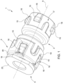
Figure 1 is a perspective view, with parts removed for clarity, of an exemplary connector for connecting pipes not falling under the scope of the present invention; -
Figures 2 and 3 are sectional views, with parts removed for clarity, of the connector ofFigure 1 in respective operational configurations; -
Figure 4 is a perspective view of a tubular sleeve of the connector ofFigure 1 ; -
Figure 5 is a perspective view of an end insert of the connector ofFigure 1 ; -
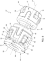
Figure 6 is a perspective view, with parts removed for clarity, of a connector for connecting pipes manufactured in accordance with the present invention; and -
Figure 7 is a sectional view, with parts removed for clarity, of the connector ofFigure 6 . - With reference to
Figures 1-3 ,reference numeral 1 indicates, as a whole, a connector for connecting ends of two fluid transport pipes 2 (Figure 3 ). Theconnector 1 can also be used for connecting one end of a transport pipe 2 (Figure 3 ) to a further hydraulic element, such as for example a pump or a valve or a tank. - The
connector 1 is particularly applicable to hydraulic circuits of household electrical appliances, such as for example ovens, steam machines and coffee machines. - The
connector 1 comprises atubular casing 3, which extends around a main axis A; anend insert 4, which can be snap coupled to one end of thetubular casing 3; atubular sleeve 5, which is configured to be fitted around a respective fluid transport pipe 2 (Figure 3 ) and to cooperate with theend insert 4 such that a relative rotation around the main axis A of thetubular sleeve 5 within the end insert 4 results in a relative displacement of thetubular sleeve 5 with respect to theend insert 4 in a direction substantially parallel to the main axis A; and a clamping element 6 (Figures 2 and 3 ), which is housed within thetubular casing 3 and is configured to retain therespective transport pipe 2. - In particular, the
tubular casing 3, the end insert 4 and thetubular sleeve 5 are made of respective polymeric materials. - With reference to
Figures 2 and 3 , thetubular casing 3 comprises anend 7; aninner shoulder 8; aninner shoulder 9 placed between theend 7 and theinner shoulder 8 at a distance from theinner shoulder 8 along the main axis A; and a narrowing 10 configured to provide an abutment surface for one end of each transport pipe 2 (Figure 3 ) so as to clamp the sliding of each transport pipe 2 (Figure 3 ) in a direction substantially parallel to the main axis A when said transport pipe 2 (Figure 3 ) is inserted within of thetubular casing 3. - The
connector 1 comprises anannular spacer 11, which is placed on theinner shoulder 9 and is shaped to support theclamping element 6. - In particular, the
clamping element 6 comprises atoothed washer 12 provided with a plurality offlexible teeth 13 facing each other. Practically, eachflexible tooth 13 is configured to deflect when saidflexible tooth 13 enters into contact with thetubular sleeve 5 during the insertion of thetubular sleeve 5 within thetubular casing 3. - Furthermore, the
connector 1 comprises anannular sealing element 14, preferably made of a polymeric material, which is housed within thetubular casing 3 at a distance from theclamping element 6 and is configured to interfere with the fluid transport pipe 2 (Figure 3 ). - In particular, the
annular sealing element 14 is an O-ring. The term "O-ring" means a rubber ring used as mechanical gasket. The O-rings are designed to be inserted in suitable housings and to be compressed during the assembly of two or more parts, thus creating a sealing gasket. - More specifically, the
annular sealing element 14 is supported by theinner shoulder 8. In this manner, theannular sealing element 14 is placed at such a distance from theclamping element 6 to allow the deflection of eachflexible tooth 13 without saidflexible tooth 13 entering into contact with theannular sealing element 14 during the insertion of thetubular sleeve 5 within thetubular casing 3. - With reference to
Figure 1 , thetubular casing 3 comprises a plurality ofengaging elements 15, each of which is placed on the outer surface of thetubular casing 3 at theend 7 and is provided with a chamferedportion 16. More specifically, thetubular casing 3 comprises fourengaging elements 15 uniformly distributed on the outer surface of thetubular casing 3 and aseat 17 obtained in the outer surface of thetubular casing 3 and placed around theengaging elements 15. - The
end insert 4 comprises acoupling portion 18 provided with a plurality ofopenings 19, each of which is configured to house a respectiveengaging element 15 of thetubular casing 3. In particular, thecoupling portion 18 is ring-shaped and is configured to be housed within theseat 17 by means of a snap coupling. - Furthermore, the
end insert 4 comprises anupper wall 20, which is substantially flat and is configured to provide an abutment surface for thetubular sleeve 5 so as to clamp the sliding of thetubular sleeve 5 in a direction substantially parallel to the main axis A when thetubular sleeve 5 is inserted within thetubular casing 3. - In the non-limiting case described and illustrated herein, the
tubular casing 3 extends symmetrically with respect to a symmetry plane P perpendicular to the main axis A and intersecting thenarrowing 10. In accordance with such configuration, theconnector 1 comprises a pair ofend inserts 4, a pair oftubular sleeves 5, a pair ofclamping elements 6, a pair ofannular spacers 11 and a pair ofannular sealing elements 14. - In accordance with a further embodiment, not shown in the accompanying figures, the
narrowing 10 is placed in the proximity of one end of thetubular casing 3 along the main axis A. - With reference to
Figure 4 , thetubular sleeve 5 comprises atubular portion 21; twopins 22, each of which is placed on the outer surface of thetubular portion 21; and acollar 23 shaped to allow the fastening tool to be gripped thereon, not shown in the accompanying figures. - The
tubular portion 21 is provided with twonotches 24 configured to favour the deformation of thetubular portion 21 during the insertion of thetubular sleeve 5 within thetubular casing 3. - With reference to
Figure 5 , theend insert 4 is provided with twointernal seats 25, each of which is obtained in a cylindricalinner wall 26 of theend insert 4. - Each
internal seat 25 is shaped to house arespective pin 22 of thetubular sleeve 5 and to guide saidpin 22 along a segment of a helical trajectory, which develops around the main axis A. - In particular, the segment of helical trajectory defined by each
internal seat 25 is shaped to cause a displacement of thetubular sleeve 5 of the order of a few millimetres in a direction substantially parallel to the main axis A. - Furthermore, each
internal seat 25 is shaped to allow the relative displacement of therespective pin 22 of thetubular sleeve 5 with respect to theend insert 4 in a direction substantially parallel to the main axis A. - With reference to
Figures 6 and7 , aconnector 27 for connecting fluid transport pipes 2 (Figure 3 ) manufactured in accordance with the present invention is shown. - The
connector 27 comprises atubular casing 28, which extends around a main axis A; anend insert 29, which can be snap coupled to one end of thetubular casing 28 and comprises anupper wall 30 provided with at least onepin 31; atubular sleeve 32, which is configured to be fitted around a respective fluid transport pipe 2 (Figure 3 ) and to cooperate with the end insert 29 so as to be snap engaged/disengaged to the end insert 29 by means of a force exerted on thetubular sleeve 32 in a direction substantially parallel to the main axis A. - The
tubular sleeve 32 comprises at one end acollar 33 provided with at least oneopening 34, which is shaped to receive therespective pin 31 during the displacement of thetubular sleeve 32 towards theend insert 29 in a direction substantially parallel to the main axis A. - In particular, the
end insert 29 comprises fourpins 31, uniformly distributed on theupper wall 30 around the main axis A. Thecollar 33 is provided with fouropenings 34 uniformly distributed around the main axis A. - More specifically, each
pin 31 extends from theupper wall 30 along a direction substantially parallel to the main axis A. - With reference to
Figure 7 , theend insert 29 comprises aninner surface 35 provided with aninner shoulder 36. Thetubular sleeve 32 comprises at one end a engagingportion 37, which is provided with astep 38 and is configured to interfere with theinner shoulder 36 so as to snap engage/disengage with theend insert 29. - Similarly to the
connector 1 shown inFigures 1-3 , theconnector 27 comprises theclamping element 6, which is housed within thetubular casing 28 and is configured to retain the fluid transport pipe 2 (Figure 3 ); theannular spacer 11, which is shaped to support theclamping element 6; and theannular sealing element 14, preferably made of a polymeric material, which is configured to interfere with the fluid transport pipe 2 (Figure 3 ). - In use and with reference to
Figure 2 , thetubular sleeve 5 is inserted in theend insert 4 in a first position, in which eachpin 22 is housed in the respectiveinternal seat 25 and thecollar 23 is positioned at a distance from theupper wall 20 of theend insert 4. - With reference to
Figure 3 , afluid transport pipe 2 is inserted within thetubular casing 3 passing through thetubular sleeve 5, the clampingelement 6 and theannular sealing element 14 such that the end of thefluid transport pipe 2 enters into contact with the narrowing 10. - Subsequently, the
tubular sleeve 5 is rotated with respect to theend insert 4 around the main axis A, causing the displacement along the main axis A of thetubular sleeve 5 up to a second position, in which thetubular sleeve 5 is clamped within theend insert 4 and thecollar 23 is in abutment against theupper wall 20. - More specifically, the rotation of the
tubular sleeve 5 around the main axis A causes the sliding of eachpin 22 in the respectiveinternal seat 25, which guides therespective pin 22 along a segment of a helical trajectory causing the displacement of thetubular sleeve 5 between the first and the second positions. - The rotation of the
tubular sleeve 5 can be carried out by means of a fastening tool, not shown in the accompanying figures. - In the displacement of the
tubular sleeve 5 from the first to the second positions, thetubular portion 21 of thetubular sleeve 5 enters into contact with saidflexible teeth 13 of thetoothed washer 12, causing the deflection of theflexible teeth 13 and the deformation of thetubular portion 21, and consequently clamping thetubular sleeve 5 within thetubular casing 3. In this manner, thefluid transport pipe 2 is compressed within thetubular portion 21 of thetubular sleeve 5, clamping the sliding of thefluid transport pipe 2 in a direction substantially parallel to the main axis A. - In accordance with an alternative mode of inserting the
tubular sleeve 5 within theend insert 4, thecollar 23 of thetubular sleeve 5 is pushed by pressure towards theupper wall 20 of theend insert 4 in a direction substantially parallel to the main axis A. In such circumstance, thetubular sleeve 5 slides in a direction substantially parallel to the main axis A, without requiring a relative rotation of thetubular sleeve 5 with respect to theend insert 4 around the main axis A. - More specifically, the insertion of the
tubular sleeve 5 within theend insert 4 causes the sliding in a direction substantially parallel to the main axis A of eachpin 22 in the respectiveinternal seat 25. - It is finally evident that variations can be made to the present invention with respect to the described embodiments without thereby departing from the scope of protection of the appended claims.
Claims (4)
- A connector for connecting pipes for transporting fluids; the connector (27) comprising:- a tubular casing (28), which extends around a main axis (A);- an end insert (29), which can be snap coupled to one end of the tubular casing (28) and comprises an upper wall (30) provided with at least one pin (31); and- a tubular sleeve (32), which is configured to be fitted around a respective fluid transport pipe (2) and to cooperate with the end insert (29) so as to be snap engaged/disengaged to the end insert (29) by a force exerted on the tubular sleeve (32) in a direction substantially parallel to the main axis (A);the tubular sleeve (32) comprising at one end a collar (33) provided with at least one opening (34), which is shaped to receive the respective pin (31) during a displacement of the tubular sleeve (32) towards the end insert (29) in a direction substantially parallel to the main axis (A).
- The connector as claimed in Claim 1, wherein the end insert (29) comprises four pins (31), uniformly distributed on the upper wall (30) around the main axis (A); the collar (33) being provided with four openings (34) uniformly distributed around the main axis (A).
- The connector as claimed in Claim 1 or 2, wherein each pin (31) extends from the upper wall (30) along a direction substantially parallel to the main axis (A).
- The connector as claimed in any one of the foregoing Claims, wherein the end insert (29) comprises an inner surface (35) provided with an inner shoulder (36); the tubular sleeve (32) comprising an engaging portion (37), which is configured to interfere with the inner shoulder (36) so as to snap engage/disengage with the end insert (29).
Priority Applications (1)
| Application Number | Priority Date | Filing Date | Title |
|---|---|---|---|
| SM20260096T SMT202600096T1 (en) | 2021-06-11 | 2022-06-09 | Connector and method for connecting pipes for transporting fluids |
Applications Claiming Priority (2)
| Application Number | Priority Date | Filing Date | Title |
|---|---|---|---|
| IT202100015377 | 2021-06-11 | ||
| EP22178077.8A EP4102122B1 (en) | 2021-06-11 | 2022-06-09 | Connector and method for connecting pipes for transporting fluids |
Related Parent Applications (2)
| Application Number | Title | Priority Date | Filing Date |
|---|---|---|---|
| EP22178077.8A Division EP4102122B1 (en) | 2021-06-11 | 2022-06-09 | Connector and method for connecting pipes for transporting fluids |
| EP22178077.8A Division-Into EP4102122B1 (en) | 2021-06-11 | 2022-06-09 | Connector and method for connecting pipes for transporting fluids |
Publications (4)
| Publication Number | Publication Date |
|---|---|
| EP4462002A2 true EP4462002A2 (en) | 2024-11-13 |
| EP4462002A3 EP4462002A3 (en) | 2025-01-22 |
| EP4462002B1 EP4462002B1 (en) | 2025-12-24 |
| EP4462002C0 EP4462002C0 (en) | 2025-12-24 |
Family
ID=77801842
Family Applications (2)
| Application Number | Title | Priority Date | Filing Date |
|---|---|---|---|
| EP24202802.5A Active EP4462002B1 (en) | 2021-06-11 | 2022-06-09 | Connector and method for connecting pipes for transporting fluids |
| EP22178077.8A Active EP4102122B1 (en) | 2021-06-11 | 2022-06-09 | Connector and method for connecting pipes for transporting fluids |
Family Applications After (1)
| Application Number | Title | Priority Date | Filing Date |
|---|---|---|---|
| EP22178077.8A Active EP4102122B1 (en) | 2021-06-11 | 2022-06-09 | Connector and method for connecting pipes for transporting fluids |
Country Status (4)
| Country | Link |
|---|---|
| US (2) | US12018784B2 (en) |
| EP (2) | EP4462002B1 (en) |
| CN (1) | CN115468052A (en) |
| SM (1) | SMT202600096T1 (en) |
Families Citing this family (1)
| Publication number | Priority date | Publication date | Assignee | Title |
|---|---|---|---|---|
| JP1734989S (en) * | 2022-08-08 | 2023-01-19 | pipe joint |
Family Cites Families (12)
| Publication number | Priority date | Publication date | Assignee | Title |
|---|---|---|---|---|
| DE19932602C2 (en) * | 1999-07-13 | 2002-07-11 | Voswinkel Kg | pipe coupling |
| FR2807815B1 (en) | 2000-04-12 | 2002-06-21 | Comap | REMOVABLE CONNECTION DEVICE FOR PIPE |
| JP4565776B2 (en) * | 2001-07-17 | 2010-10-20 | ニッタ・ムアー株式会社 | Pipe fitting |
| JP5114102B2 (en) * | 2007-06-15 | 2013-01-09 | ニッタ株式会社 | Pipe fitting |
| WO2013056273A2 (en) * | 2011-10-12 | 2013-04-18 | Livizone (Pty) Ltd | Push-fit fitting with grip nut for pipes |
| JP5779082B2 (en) * | 2011-12-15 | 2015-09-16 | 株式会社ブリヂストン | Fitting |
| US10161551B2 (en) * | 2015-07-09 | 2018-12-25 | A. Raymond Et Cie | Quick-connector |
| US10865922B2 (en) * | 2017-10-05 | 2020-12-15 | Novares Us Engine Components, Inc. | Anti-tamper permanent quick connect coupling device |
| GB2573165B (en) * | 2018-04-27 | 2020-11-18 | John Guest International Ltd | A connector |
| NL2024297B1 (en) * | 2019-11-22 | 2021-08-23 | Wavin Bv | A pipe coupling for receiving, holding and releasing a pipe and a method of assembling a pipe coupling |
| US11781689B2 (en) * | 2020-03-13 | 2023-10-10 | Reliance Worldwide Corporation | Push-to-connect fitting providing an insertion indication |
| EP4060217B1 (en) * | 2021-03-18 | 2025-04-30 | Hanil Tube Corporation | Quick connector with retainer and verifier |
-
2022
- 2022-06-09 SM SM20260096T patent/SMT202600096T1/en unknown
- 2022-06-09 US US17/836,297 patent/US12018784B2/en active Active
- 2022-06-09 EP EP24202802.5A patent/EP4462002B1/en active Active
- 2022-06-09 EP EP22178077.8A patent/EP4102122B1/en active Active
- 2022-06-10 CN CN202210657560.9A patent/CN115468052A/en active Pending
-
2024
- 2024-04-23 US US18/643,077 patent/US12392436B2/en active Active
Also Published As
| Publication number | Publication date |
|---|---|
| SMT202600096T1 (en) | 2026-03-09 |
| CN115468052A (en) | 2022-12-13 |
| EP4462002A3 (en) | 2025-01-22 |
| EP4102122A3 (en) | 2023-02-15 |
| EP4462002B1 (en) | 2025-12-24 |
| EP4102122A2 (en) | 2022-12-14 |
| US20220397220A1 (en) | 2022-12-15 |
| US12392436B2 (en) | 2025-08-19 |
| EP4102122C0 (en) | 2024-12-18 |
| EP4462002C0 (en) | 2025-12-24 |
| US12018784B2 (en) | 2024-06-25 |
| EP4102122B1 (en) | 2024-12-18 |
| US20240280200A1 (en) | 2024-08-22 |
Similar Documents
| Publication | Publication Date | Title |
|---|---|---|
| CN108779882B (en) | Couplings with Retainers with Tabs | |
| US11802643B2 (en) | Fluid connector | |
| CN211853130U (en) | Quick connector | |
| US3922011A (en) | Hose coupling | |
| CN110709637B (en) | Coupling element and coupling mechanism connecting first fluid delivery line to second fluid delivery line | |
| US11821558B2 (en) | Fluid connector with dry break | |
| JP6853351B2 (en) | Fittings and fitting assemblies and how to manufacture fittings | |
| KR20090057899A (en) | Tube combiner | |
| JP7349571B2 (en) | Quick connector and connection assembly with improved sealing ring locking properties | |
| US20070001450A1 (en) | Pressure activated disconnect lock coupling | |
| US12392436B2 (en) | Connector and method for connecting pipes for transporting fluids | |
| EP3167220B1 (en) | Coupling assembly with vibration lock | |
| CN116997742A (en) | Pipeline connectors and corresponding applications | |
| JP2007520670A (en) | Connector with release mechanism | |
| CN112236612B (en) | Coupling devices for hose construction | |
| JP7333868B2 (en) | Couplings and how to assemble the couplings | |
| CN111742171A (en) | Connector for loop element | |
| WO2006099568A2 (en) | Pressure activated disconnect lock coupling | |
| WO2025075843A1 (en) | Fluid connection assembly | |
| EP2976563B1 (en) | Pipe connector and system for connecting pipes | |
| CN120701842A (en) | Improved female fluid connector for quick connect and disconnect fluid couplings | |
| CN120650548A (en) | Improved male fluid connector for quick connect and disconnect fluid couplings | |
| CN121520476A (en) | Detachable pipe fittings | |
| CN116391088A (en) | fluid connection unit |
Legal Events
| Date | Code | Title | Description |
|---|---|---|---|
| REG | Reference to a national code |
Ref country code: HR Ref legal event code: TUEP Ref document number: P20260075T Country of ref document: HR |
|
| PUAI | Public reference made under article 153(3) epc to a published international application that has entered the european phase |
Free format text: ORIGINAL CODE: 0009012 |
|
| STAA | Information on the status of an ep patent application or granted ep patent |
Free format text: STATUS: THE APPLICATION HAS BEEN PUBLISHED |
|
| AC | Divisional application: reference to earlier application |
Ref document number: 4102122 Country of ref document: EP Kind code of ref document: P |
|
| AK | Designated contracting states |
Kind code of ref document: A2 Designated state(s): AL AT BE BG CH CY CZ DE DK EE ES FI FR GB GR HR HU IE IS IT LI LT LU LV MC MK MT NL NO PL PT RO RS SE SI SK SM TR |
|
| PUAL | Search report despatched |
Free format text: ORIGINAL CODE: 0009013 |
|
| AK | Designated contracting states |
Kind code of ref document: A3 Designated state(s): AL AT BE BG CH CY CZ DE DK EE ES FI FR GB GR HR HU IE IS IT LI LT LU LV MC MK MT NL NO PL PT RO RS SE SI SK SM TR |
|
| RIC1 | Information provided on ipc code assigned before grant |
Ipc: F16L 37/091 20060101AFI20241213BHEP |
|
| STAA | Information on the status of an ep patent application or granted ep patent |
Free format text: STATUS: REQUEST FOR EXAMINATION WAS MADE |
|
| GRAP | Despatch of communication of intention to grant a patent |
Free format text: ORIGINAL CODE: EPIDOSNIGR1 |
|
| STAA | Information on the status of an ep patent application or granted ep patent |
Free format text: STATUS: GRANT OF PATENT IS INTENDED |
|
| 17P | Request for examination filed |
Effective date: 20250630 |
|
| INTG | Intention to grant announced |
Effective date: 20250718 |
|
| GRAS | Grant fee paid |
Free format text: ORIGINAL CODE: EPIDOSNIGR3 |
|
| GRAA | (expected) grant |
Free format text: ORIGINAL CODE: 0009210 |
|
| STAA | Information on the status of an ep patent application or granted ep patent |
Free format text: STATUS: THE PATENT HAS BEEN GRANTED |
|
| AC | Divisional application: reference to earlier application |
Ref document number: 4102122 Country of ref document: EP Kind code of ref document: P |
|
| AK | Designated contracting states |
Kind code of ref document: B1 Designated state(s): AL AT BE BG CH CY CZ DE DK EE ES FI FR GB GR HR HU IE IS IT LI LT LU LV MC MK MT NL NO PL PT RO RS SE SI SK SM TR |
|
| REG | Reference to a national code |
Ref country code: CH Ref legal event code: F10 Free format text: ST27 STATUS EVENT CODE: U-0-0-F10-F00 (AS PROVIDED BY THE NATIONAL OFFICE) Effective date: 20251224 Ref country code: GB Ref legal event code: FG4D |
|
| REG | Reference to a national code |
Ref country code: DE Ref legal event code: R096 Ref document number: 602022027670 Country of ref document: DE |
|
| U01 | Request for unitary effect filed |
Effective date: 20251224 |
|
| U07 | Unitary effect registered |
Designated state(s): AT BE BG DE DK EE FI FR IT LT LU LV MT NL PT RO SE SI Effective date: 20260109 |
|
| REG | Reference to a national code |
Ref country code: CH Ref legal event code: R17 Free format text: ST27 STATUS EVENT CODE: U-0-0-R10-R17 (AS PROVIDED BY THE NATIONAL OFFICE) Effective date: 20260227 |