EP4461996A1 - Modular shifting system - Google Patents
Modular shifting system Download PDFInfo
- Publication number
- EP4461996A1 EP4461996A1 EP23172174.7A EP23172174A EP4461996A1 EP 4461996 A1 EP4461996 A1 EP 4461996A1 EP 23172174 A EP23172174 A EP 23172174A EP 4461996 A1 EP4461996 A1 EP 4461996A1
- Authority
- EP
- European Patent Office
- Prior art keywords
- shift
- shift device
- shifting
- housing
- transmission
- Prior art date
- Legal status (The legal status is an assumption and is not a legal conclusion. Google has not performed a legal analysis and makes no representation as to the accuracy of the status listed.)
- Pending
Links
Images


Classifications
-
- F—MECHANICAL ENGINEERING; LIGHTING; HEATING; WEAPONS; BLASTING
- F16—ENGINEERING ELEMENTS AND UNITS; GENERAL MEASURES FOR PRODUCING AND MAINTAINING EFFECTIVE FUNCTIONING OF MACHINES OR INSTALLATIONS; THERMAL INSULATION IN GENERAL
- F16H—GEARING
- F16H61/00—Control functions within control units of change-speed- or reversing-gearings for conveying rotary motion ; Control of exclusively fluid gearing, friction gearing, gearings with endless flexible members or other particular types of gearing
- F16H61/26—Generation or transmission of movements for final actuating mechanisms
- F16H61/28—Generation or transmission of movements for final actuating mechanisms with at least one movement of the final actuating mechanism being caused by a non-mechanical force, e.g. power-assisted
- F16H61/30—Hydraulic or pneumatic motors or related fluid control means therefor
-
- F—MECHANICAL ENGINEERING; LIGHTING; HEATING; WEAPONS; BLASTING
- F16—ENGINEERING ELEMENTS AND UNITS; GENERAL MEASURES FOR PRODUCING AND MAINTAINING EFFECTIVE FUNCTIONING OF MACHINES OR INSTALLATIONS; THERMAL INSULATION IN GENERAL
- F16H—GEARING
- F16H61/00—Control functions within control units of change-speed- or reversing-gearings for conveying rotary motion ; Control of exclusively fluid gearing, friction gearing, gearings with endless flexible members or other particular types of gearing
- F16H61/02—Control functions within control units of change-speed- or reversing-gearings for conveying rotary motion ; Control of exclusively fluid gearing, friction gearing, gearings with endless flexible members or other particular types of gearing characterised by the signals used
- F16H61/0202—Control functions within control units of change-speed- or reversing-gearings for conveying rotary motion ; Control of exclusively fluid gearing, friction gearing, gearings with endless flexible members or other particular types of gearing characterised by the signals used the signals being electric
- F16H61/0204—Control functions within control units of change-speed- or reversing-gearings for conveying rotary motion ; Control of exclusively fluid gearing, friction gearing, gearings with endless flexible members or other particular types of gearing characterised by the signals used the signals being electric for gearshift control, e.g. control functions for performing shifting or generation of shift signal
-
- F—MECHANICAL ENGINEERING; LIGHTING; HEATING; WEAPONS; BLASTING
- F16—ENGINEERING ELEMENTS AND UNITS; GENERAL MEASURES FOR PRODUCING AND MAINTAINING EFFECTIVE FUNCTIONING OF MACHINES OR INSTALLATIONS; THERMAL INSULATION IN GENERAL
- F16H—GEARING
- F16H61/00—Control functions within control units of change-speed- or reversing-gearings for conveying rotary motion ; Control of exclusively fluid gearing, friction gearing, gearings with endless flexible members or other particular types of gearing
- F16H61/26—Generation or transmission of movements for final actuating mechanisms
- F16H61/28—Generation or transmission of movements for final actuating mechanisms with at least one movement of the final actuating mechanism being caused by a non-mechanical force, e.g. power-assisted
- F16H61/32—Electric motors , actuators or related electrical control means therefor
-
- F—MECHANICAL ENGINEERING; LIGHTING; HEATING; WEAPONS; BLASTING
- F16—ENGINEERING ELEMENTS AND UNITS; GENERAL MEASURES FOR PRODUCING AND MAINTAINING EFFECTIVE FUNCTIONING OF MACHINES OR INSTALLATIONS; THERMAL INSULATION IN GENERAL
- F16H—GEARING
- F16H63/00—Control outputs from the control unit to change-speed- or reversing-gearings for conveying rotary motion or to other devices than the final output mechanism
- F16H63/02—Final output mechanisms therefor; Actuating means for the final output mechanisms
- F16H63/04—Final output mechanisms therefor; Actuating means for the final output mechanisms a single final output mechanism being moved by a single final actuating mechanism
- F16H63/06—Final output mechanisms therefor; Actuating means for the final output mechanisms a single final output mechanism being moved by a single final actuating mechanism the final output mechanism having an indefinite number of positions
- F16H63/065—Final output mechanisms therefor; Actuating means for the final output mechanisms a single final output mechanism being moved by a single final actuating mechanism the final output mechanism having an indefinite number of positions hydraulic actuating means
-
- F—MECHANICAL ENGINEERING; LIGHTING; HEATING; WEAPONS; BLASTING
- F16—ENGINEERING ELEMENTS AND UNITS; GENERAL MEASURES FOR PRODUCING AND MAINTAINING EFFECTIVE FUNCTIONING OF MACHINES OR INSTALLATIONS; THERMAL INSULATION IN GENERAL
- F16H—GEARING
- F16H63/00—Control outputs from the control unit to change-speed- or reversing-gearings for conveying rotary motion or to other devices than the final output mechanism
- F16H63/02—Final output mechanisms therefor; Actuating means for the final output mechanisms
- F16H63/08—Multiple final output mechanisms being moved by a single common final actuating mechanism
- F16H63/16—Multiple final output mechanisms being moved by a single common final actuating mechanism the final output mechanisms being successively actuated by progressive movement of the final actuating mechanism
- F16H63/18—Multiple final output mechanisms being moved by a single common final actuating mechanism the final output mechanisms being successively actuated by progressive movement of the final actuating mechanism the final actuating mechanism comprising cams
-
- F—MECHANICAL ENGINEERING; LIGHTING; HEATING; WEAPONS; BLASTING
- F16—ENGINEERING ELEMENTS AND UNITS; GENERAL MEASURES FOR PRODUCING AND MAINTAINING EFFECTIVE FUNCTIONING OF MACHINES OR INSTALLATIONS; THERMAL INSULATION IN GENERAL
- F16H—GEARING
- F16H63/00—Control outputs from the control unit to change-speed- or reversing-gearings for conveying rotary motion or to other devices than the final output mechanism
- F16H63/02—Final output mechanisms therefor; Actuating means for the final output mechanisms
- F16H63/30—Constructional features of the final output mechanisms
- F16H63/3023—Constructional features of the final output mechanisms the final output mechanisms comprising elements moved by fluid pressure
-
- F—MECHANICAL ENGINEERING; LIGHTING; HEATING; WEAPONS; BLASTING
- F16—ENGINEERING ELEMENTS AND UNITS; GENERAL MEASURES FOR PRODUCING AND MAINTAINING EFFECTIVE FUNCTIONING OF MACHINES OR INSTALLATIONS; THERMAL INSULATION IN GENERAL
- F16H—GEARING
- F16H63/00—Control outputs from the control unit to change-speed- or reversing-gearings for conveying rotary motion or to other devices than the final output mechanism
- F16H63/02—Final output mechanisms therefor; Actuating means for the final output mechanisms
- F16H63/30—Constructional features of the final output mechanisms
- F16H63/304—Constructional features of the final output mechanisms the final output mechanisms comprising elements moved by electrical or magnetic force
-
- F—MECHANICAL ENGINEERING; LIGHTING; HEATING; WEAPONS; BLASTING
- F16—ENGINEERING ELEMENTS AND UNITS; GENERAL MEASURES FOR PRODUCING AND MAINTAINING EFFECTIVE FUNCTIONING OF MACHINES OR INSTALLATIONS; THERMAL INSULATION IN GENERAL
- F16H—GEARING
- F16H63/00—Control outputs from the control unit to change-speed- or reversing-gearings for conveying rotary motion or to other devices than the final output mechanism
- F16H63/02—Final output mechanisms therefor; Actuating means for the final output mechanisms
- F16H63/30—Constructional features of the final output mechanisms
- F16H63/32—Gear shift yokes, e.g. shift forks
-
- F—MECHANICAL ENGINEERING; LIGHTING; HEATING; WEAPONS; BLASTING
- F16—ENGINEERING ELEMENTS AND UNITS; GENERAL MEASURES FOR PRODUCING AND MAINTAINING EFFECTIVE FUNCTIONING OF MACHINES OR INSTALLATIONS; THERMAL INSULATION IN GENERAL
- F16H—GEARING
- F16H61/00—Control functions within control units of change-speed- or reversing-gearings for conveying rotary motion ; Control of exclusively fluid gearing, friction gearing, gearings with endless flexible members or other particular types of gearing
- F16H61/26—Generation or transmission of movements for final actuating mechanisms
- F16H61/28—Generation or transmission of movements for final actuating mechanisms with at least one movement of the final actuating mechanism being caused by a non-mechanical force, e.g. power-assisted
- F16H61/30—Hydraulic or pneumatic motors or related fluid control means therefor
- F16H2061/307—Actuators with three or more defined positions, e.g. three position servos
-
- F—MECHANICAL ENGINEERING; LIGHTING; HEATING; WEAPONS; BLASTING
- F16—ENGINEERING ELEMENTS AND UNITS; GENERAL MEASURES FOR PRODUCING AND MAINTAINING EFFECTIVE FUNCTIONING OF MACHINES OR INSTALLATIONS; THERMAL INSULATION IN GENERAL
- F16H—GEARING
- F16H61/00—Control functions within control units of change-speed- or reversing-gearings for conveying rotary motion ; Control of exclusively fluid gearing, friction gearing, gearings with endless flexible members or other particular types of gearing
- F16H61/26—Generation or transmission of movements for final actuating mechanisms
- F16H61/28—Generation or transmission of movements for final actuating mechanisms with at least one movement of the final actuating mechanism being caused by a non-mechanical force, e.g. power-assisted
- F16H61/30—Hydraulic or pneumatic motors or related fluid control means therefor
- F16H2061/308—Modular hydraulic shift units, i.e. preassembled actuator units for select and shift movements adapted for being mounted on transmission casing
-
- F—MECHANICAL ENGINEERING; LIGHTING; HEATING; WEAPONS; BLASTING
- F16—ENGINEERING ELEMENTS AND UNITS; GENERAL MEASURES FOR PRODUCING AND MAINTAINING EFFECTIVE FUNCTIONING OF MACHINES OR INSTALLATIONS; THERMAL INSULATION IN GENERAL
- F16H—GEARING
- F16H63/00—Control outputs from the control unit to change-speed- or reversing-gearings for conveying rotary motion or to other devices than the final output mechanism
- F16H2063/005—Preassembled gear shift units for mounting on gear case
-
- F—MECHANICAL ENGINEERING; LIGHTING; HEATING; WEAPONS; BLASTING
- F16—ENGINEERING ELEMENTS AND UNITS; GENERAL MEASURES FOR PRODUCING AND MAINTAINING EFFECTIVE FUNCTIONING OF MACHINES OR INSTALLATIONS; THERMAL INSULATION IN GENERAL
- F16H—GEARING
- F16H63/00—Control outputs from the control unit to change-speed- or reversing-gearings for conveying rotary motion or to other devices than the final output mechanism
- F16H63/02—Final output mechanisms therefor; Actuating means for the final output mechanisms
- F16H63/30—Constructional features of the final output mechanisms
- F16H63/304—Constructional features of the final output mechanisms the final output mechanisms comprising elements moved by electrical or magnetic force
- F16H2063/3056—Constructional features of the final output mechanisms the final output mechanisms comprising elements moved by electrical or magnetic force using cam or crank gearing
-
- F—MECHANICAL ENGINEERING; LIGHTING; HEATING; WEAPONS; BLASTING
- F16—ENGINEERING ELEMENTS AND UNITS; GENERAL MEASURES FOR PRODUCING AND MAINTAINING EFFECTIVE FUNCTIONING OF MACHINES OR INSTALLATIONS; THERMAL INSULATION IN GENERAL
- F16H—GEARING
- F16H2200/00—Transmissions for multiple ratios
- F16H2200/003—Transmissions for multiple ratios characterised by the number of forward speeds
- F16H2200/0039—Transmissions for multiple ratios characterised by the number of forward speeds the gear ratios comprising three forward speeds
Definitions
- the present invention relates to a modular shifting system.
- the present invention relates to a pneumatically actuated shift device for the modular shifting system.
- a shifting system includes a transmission providing different gear ratios between an output shaft and an input shaft and a shift device for shifting between the different gear ratios of the transmission.
- a transmission providing different gear ratios between an output shaft and an input shaft and a shift device for shifting between the different gear ratios of the transmission.
- an electrically actuated shift device and a pneumatically actuated shift device for the shifting system is known.
- the selection of either the electrically actuated shift device or the pneumatically actuated shift device depends on various factors such as the intended use of the shifting system, customer requirements, etc. Due to the different designs and dimensions of the differently actuated shift devices, the selection of the shift device influences the design of the transmission (and/or the transmission housing), the required installation space of the transmission, and the arrangement of surrounding components, e.g., in a vehicle chassis or a vehicle body.
- the selection of the shift device must therefore be made early in the manufacturing process, which reduces the flexibility. Moreover, the selection of the shift device affects the design and arrangement of adjacent components, which increases the number of different components required and conflicts with the need to achieve the most efficient manufacturing process. In order to make the manufacturing process cost-effective, it is desirable to reduce the number of different components required.
- a pneumatically actuated shift device for the modular shifting system according to the invention is the subject-matter of claim 5. Further advantageous developments are set out in the dependent claims.
- a modular shifting system includes a shift device for shifting between at least two gear ratios, which is detachably attached to a transmission housing.
- the shift device is one of an electrically actuated shift device and a pneumatically actuated shift device and the modular shifting system is configured such that the electrically actuated shift device is interchangeable with the pneumatically actuated shift device and vice versa.
- the electrically and the pneumatically actuated shift devices can be detachably attached to the transmission housing and are interchangeable with each other, the selection of the shift device does not affect the design of the transmission and/or the transmission housing of the shifting system. As a result, the number of different components required can be reduced, which makes the manufacturing process more cost-effective. Moreover, the selection of the shift device can be made later in the manufacturing process facilitating the adaption of the shifting system to customer and market requirements. Consequently, the manufacturing process can be made more flexible.
- the dimensions of a housing of the electrically actuated shift device may substantially be equal to the dimensions of a housing of the pneumatically actuated shift device.
- an installation space required for the modular shifting system is independent of the shift device selection.
- the selection of the shift device does not affect the installation space of the modular shifting system and the influence on the arrangement of surrounding components, e.g., in a vehicle chassis or a vehicle body, can be reduced. This allows the selection of the shift device to be made later in the manufacturing process, making the manufacturing process more flexible.
- the transmission may include a first shift fork axially shiftable by axially shifting a first follower and a second shift fork axially shiftable by axially shifting a second follower.
- the first follower and the second follower may be exposed to the outside of the transmission housing.
- Both the electrically actuated shift device and the pneumatically actuated shift device may include shifting means positioned so as to be able to axially shift the first follower and the second follower.
- the selection of the shift device does not affect the design of the transmission of the shifting system, in particular, the design and the arrangement of the followers intended for the communication with the shift device.
- the number of different components required can be reduced, which makes the manufacturing process more cost-effective.
- the manufacturing of the transmission is not affected by the selection of the shift device.
- the manufacturing process can be made more flexible.
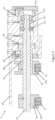
- Figure 1 illustrates a schematic sectional view of the modular shifting system having an electrically actuated shift device 2 attached to a transmission housing 16.
- Figure 2 illustrates a schematic sectional view of the modular shifting system having a pneumatically actuated shift device 3 attached to a transmission housing 16.
- the modular shifting system comprises a transmission 1.
- the transmission 1 includes an input shaft (not shown in the figures) configured to be connected to a drive source, such as an engine or motor, and an output shaft (not shown in the figures) configured to be connected to driven components, such as wheels of a vehicle.
- the input shaft and the output shaft are accommodated in and rotatably supported by the transmission housing 16.
- the transmission 1 further includes multiple (three in the present embodiment shown in the figures) gear trains accommodated in the transmission housing 16 and selectively transmitting torque from the input shaft to the output shaft.
- the gear trains provide different gear ratios for establishing a transmission ratio between the output shaft and the input shaft.
- Each of the gear train is constituted, for example, by a gear provided on the input shaft and a gear provided on the output shaft meshing with the gear provided on the input shaft.
- the gear provided on the input shaft is axially fixed and rotatably supported on the input shaft.
- the gear can be rotationally locked to the input shaft by an engagement with a dog clutch provided on the input shaft.
- the dog clutch is rotationally locked to the input shaft but axially movable relative to the input shaft.
- the dog clutch is allowed to engage and disengage with the gear by axially reciprocating on the input shaft relative to the gear.
- An axial movement of the dog clutch is caused by a shift fork linked to the dog clutch.
- the shift fork is axially movably supported on a sliding rod 15.
- the shift fork is coupled to a follower via a spring mechanism (so called "blocker spring").
- blocker spring By axially shifting the follower, the shift fork is axially shifted, and the dog clutch coupled to the shift fork is engaged with or disengaged from the gear.
- the spring mechanism is capable to temporarily compensate the shifting movement of the follower when the dog clutch is prevented from shifting during the engagement process with the gear, for example, due to a tooth-to-tooth position with the gear, or during the disengagement process with the gear, for example, due to torque still acting on the engagement between the dog clutch and the gear. In this way, the spring mechanism serves to prevent overloading of an actuator that drives the axial movement of the follower.
- the transmission 1 includes a first gear 111, a second gear 112, and a third gear 113.
- the first gear 111 and the second gear 112 can be rotationally locked to the input shaft by means of a first dog clutch 110.
- the third gear 113 can be rotationally locked to the input shaft by means of a second dog clutch 120.
- the first dog clutch 110 is linked to a first shift fork 11, and the second dog clutch 120 is linked to a second shift fork 12 axially movably supported on the sliding rod 15.
- the first shift fork 11 is axially shiftable by a first follower 13 supported on the sliding rod 15.
- the second shift fork 12 is axially shiftable by a second follower 14 supported on the sliding rod 15.
- the first follower 13 and the second follower 14 are provided in the transmission housing 16 so as to be exposed to the outside of the transmission housing 16.
- the first and the second followers 13, 14 are axially shiftable by corresponding shifting means 23, 24, 33, 34 provided in the respective shift device 2, 3 attached to the transmission housing 16.
- the first shift fork 11 is shifted towards the first axial direction thereby moving the first dog clutch 110 from a neutral position, in which the first dog clutch 110 is disengaged with the first and second gears 111, 112, to a first engaged position, in which the first dog clutch 110 is engaged with the first gear 111.
- the first shift fork 11 is shifted towards the second axial direction thereby moving the first dog clutch 110 from a neutral position, in which the first dog clutch 110 is disengaged with the first and second gears 111, 112, to a second engaged position, in which the first dog clutch 110 is engaged with the second gear 112.
- the second shift fork 12 is shifted towards the first axial direction thereby moving the second dog clutch 120 from a neutral position, in which the second dog clutch 120 is disengaged with the third gear 113, to an engaged position, in which the second dog clutch 120 is engaged with the third gear 113.
- an electrically actuated shift device 2 can be attached to the transmission housing 16.
- the electrically actuated shift device 2 comprises an actuator, such as a stepper motor, which is capable of rotating a shifting shaft 21 of the shift device 2 by a specific rotation angle.
- the shifting shaft 21 is accommodated in and rotatably supported by a housing 26 of the shift device 2.
- the shifting shaft 21 is provided with a first shifting means 23 and a second shifting means 24.
- the first and second shifting means 23, 24 are formed in a disk-shaped manner protruding radially outwardly from the shifting shaft 21 and extending in a circumferential direction.
- Each of the shifting means 23, 24 comprises a circumferential recess 231, 241 radially recessed from a peripheral surface of the shifting means 23, 24 towards an axial center and extending in the circumferential direction.
- the circumferential recesses 231, 241 are formed to include inclined portions (not shown in the figures) that are inclined with respect to a plane perpendicular to the axial direction of the shifting shaft 21.
- the circumferential recesses 231, 241 of the first and the second shifting means 23, 24 are at least partially exposed to the outside through a correspondingly arranged opening in the housing 26 of the shift device 2.
- the housing 26 of the electrically actuated shift device 2 can be fixed to the transmission housing 16 by fixing means such as screws.
- the first follower 13 engages with the circumferential recess 231 of the first shifting means 23 and the second follower 14 engages with the circumferential recess 241 of the second shifting means 24. Therefore, when the first and second shifting means 23, 24 are rotated by actuation of the stepper motor, the first and second followers 13, 14 can be axially shifted by the inclined portions of the circumferential recesses 231, 241 engaged with the first and second followers 13, 14.
- Figure 1 shows the electrically actuated shift device 2 in a neutral position. That is, the first and second shifting means 23, 24 engaged with the first and second followers 13, 14, are positioned such that the first dog clutch 110 is not engaged with the first and second gears 111, 112 and the second dog clutch 120 is not engaged with the third gear 113.
- the stepper motor When a shifting command is issued, for example, by a driver of a vehicle provided with the modular shifting system, the stepper motor is actuated and rotates by a specific rotation angle in a specific rotation direction.
- the rotation of the stepper motor causes the shifting shaft 21 and the first and second shifting means 23, 24 to rotate by the specific rotation angle in the specific rotation direction.
- the first and second shifting means 23, 24 rotate, the first and second followers 13, 14 slide within the respective recess of the first and second shifting means 23, 24.
- the first follower 13 sliding within the recess of the first shifting means 23 reaches one of the inclined portions of the recess, the first follower 13 is axially shifted by the rotating first shifting means 23.
- the first shift fork 11 is axially shifted, thereby moving the first dog clutch 110, e.g., from the neutral position to the first engaged position in which the dog clutch engages with the first gear 111.
- the first dog clutch 110 can be engaged with either the first gear 111 or the second gear 112, and the second dog clutch 120 can be engaged with the third gear 113.
- a pneumatically actuated shift device 3 can be attached to the transmission housing 16. Similar to the electrically actuated shift device 2, the pneumatically actuated shift device 2 also comprises a first shifting means 33 engaging with the first follower 13 of the transmission 1 and a second shifting means 34 engaging with the second follower 14 of the transmission 1. However, the shifting of the first and second followers 13, 14 is not caused by rotation but by axial translation of the first and second shifting means 33, 34 in the axial direction. In particular, the first and second shifting means 33, 34 of the pneumatically actuated shift device 3 are reciprocated in the axial direction.
- the pneumatically actuated shift device 3 includes a first shift rod 31 and a second shift rod 32.
- the first shift rod 31 is radially supported by a housing 36 of the pneumatically actuated shift device 3 so as to be slidably movable in an axial direction with respect to the housing 36. That is, the first shift rod 31 is shiftable in a first axial direction (e.g., to the left in figures 2 and 3 ) and in a second axial direction (e.g., to the right in figures 2 and 3 ) opposite to the first axial direction.
- the first shifting means 33 is fixed to the first shift rod 31 so as to move integrally with the first shift rod 31.
- the first shifting means 33 comprises a recessed portion 331 for engaging with the first follower 13.
- the second shift rod 32 is radially supported by the first shift rod 31 so as to be slidably movable in the axial direction with respect to the housing 36 and the first shift rod 31. That is, the second shift rod 32 is shiftable in the first axial direction and in the second axial direction.
- the second shift rod 32 includes a central hollow portion penetrating the second shift rod 32 in the axial direction.
- the first shift rod 31 is inserted into the central hollow portion so as to axially penetrate the second shift rod 32.
- the second shifting means 34 is fixed to the second shift rod 32 so as to move integrally with the second shift rod 32.
- the second shifting means 34 comprises a recessed portion 341 for engaging with the second follower 14.
- the recessed portions 331, 341 of the first and the second shifting means 33, 34 are at least partially exposed to the outside through a correspondingly arranged opening in the housing 36 of the shift device 3.
- the housing 36 of the pneumatically actuated shift device 3 can be fixed to the transmission housing 16 by fixing means such as screws.
- the housing 36 of the pneumatically actuated shift device 3 includes at an axial end portion in the second axial direction a first chamber 37 and a second chamber 38.
- the first chamber 37 is substantially formed as a blind hole opened in the second axial direction.
- the opening of the first chamber 37 is covered by a first cover 371 in an airtight manner.
- the second chamber 38 is substantially formed as a blind hole opened in the first axial direction.
- the opening of the second chamber 38 is covered by a second cover 381 in an airtight manner.
- a through hole extending in the axial direction is provided between the first chamber 37 and the second chamber 38.
- the first shift rod 31 is inserted into the through hole such that an axial end portion of the first shift rod 31 in the second axial direction is accommodated in the first chamber 37 and the first shift rod 31 passes through the second chamber 38 and a corresponding hole in the second cover 381.
- the first shift rod 31 comprises a first piston member 311 and a second piston member 312, 313 arranged on the axial end portion of the first piston member 311 in the second axial direction.
- the first piston member 311 divides the first chamber 37 of the housing 36 into a first space S1 and a second space S2.
- the second piston member 312, 313 divides the first chamber 37 into the second space S2 and a third space S3. Pressurized air can be supplied to and discharged from the first space S1 by a first supply path, the second space S2 by a second supply path, and the third space S3 by a third supply path.
- An axial end side of the first piston member 311 in the first axial direction abuts on a step provided on the first shift rod 31.
- An outer peripheral surface of the first piston member 311 slidably contacts an inner peripheral surface of the first chamber 37 so as to separate the first space S1 and the second space S2 in an airtight manner.
- the second piston member 312, 313 comprises an inner piston element 312 and an outer piston element 313 positioned on a radially outer side of the inner piston element 312.
- the inner piston element 312 is substantially formed by a sleeve having a flange on the axial end side in the second axial direction projecting radially outward.
- the inner piston element 312 (in particular, an axially end surface of the inner piston element 312 in the first axial direction) abuts the first piston member 311.
- the first piston member 311 and the inner piston element 312 are axially fixed to the first shift rod 31 by, for example, a retaining ring. That is, the inner piston element 312 is sandwiched between the first piston member 311 and the retaining ring.
- the outer piston element 313 is substantially formed by a sleeve having a flange on the axial end side in the second axial direction projecting radially outward and a ring-shaped hook portion on the axial end side in the first axial direction projecting radially inward.
- the inner piston element 312 is inserted into the outer piston element 313 such that an inner peripheral surface of the outer piston element 313 slides on an outer peripheral surface of the flange of the inner piston element 312 and an inner peripheral surface of the hook portion slides on an outer peripheral surface of the inner piston element 312.
- the axial movement of the outer piston element 313 in the second axial direction relative to the inner piston element 312 is restricted by the hook portion abutting the flange of the inner piston element 312.
- the axial movement of the outer piston element 313 in the first axial direction relative to the inner piston element 312 is restricted by the hook portion abutting the first piston member 311 (the axial end side of the first piston member 311 in the second axial direction).
- An outer peripheral surface of the flange of the outer piston element 313 slidably contacts an inner peripheral surface of the first chamber 37 so as to separate the second space S2 and the third space S3 in an airtight manner.
- the second shift rod 32 is substantially formed by a sleeve having a flange on the axial end side in the second axial direction projecting radially outward. An axial end portion of the second shift rod 32 in the second axial direction including the flange is inserted into the second chamber 38. The second shift rod 32 passes through the second cover 381 so that the axial end portion of the second shift rod 32 in the first axial direction projects from the second chamber 38.
- the second shifting means 34 is fixed to the axial end portion of the second shift rod 32 in the first axial direction projecting from the second chamber 38.
- An outer peripheral surface of the flange of the second shift rod 32 slidably contacts an inner peripheral surface of the second chamber 38 so as to divide the second chamber 38 into a fourth space S4 and a fifth space S5 and to separate the fourth space S4 and the fifth space S5 in an airtight manner. Pressurized air can be supplied to and discharged from the fourth space S4 by a fourth supply path and the fifth space S5 by a fifth supply path.
- Figures 2 and 3 show the pneumatically actuated shift device 3 in a neutral position. That is, the first and second shifting means 33, 34 engaged with the corresponding one of the first and second followers 13, 14, are positioned such that the first dog clutch 110 is not engaged with the first and second gears 111, 113 and the second dog clutch 120 is not engaged with the third gear 113.
- the flange of the second shift rod 32 When the second shift rod 32 is in a position corresponding to the neutral position of the shift device 3, the flange of the second shift rod 32, in particular, an axial end surface of the flange in the second axial direction, abuts an axial end surface of the second chamber 38.
- pressurized air is supplied to one or more of the first to fifth spaces S1 to S5 via the supply paths, to shift the first and second shift rod 31, 32 in the axial direction.
- the supply of pressurized air is controlled, for example, by corresponding solenoid valves.
- the solenoid valves can be directly integrated on the housing 36 of the pneumatically actuated shift device 3.
- the outer piston element 313 is shifted relative to the inner piston element 312 until the hook portion of the outer piston element 313 abuts the flange of the inner piston element 312.
- the axial force exerted on the outer piston element 313 of the second piston member 312, 313 urges the first shift rod 31 in the second axial direction. Since the surface of the outer piston element 313 exposed to the pressure within the space S2 is larger than the surface of the first piston member 311 exposed to the pressure within the space S2, the axial force urging the first shift rod 31 to the second axial direction is larger than the axial force urging the first shift rod 31 to the first axial direction. As a result, the first shift rod 31 is returned to the position corresponding to the neutral position of the shift device 3 and the first dog clutch 110 is disengaged with the first gear 111 or the second gear 112.
- the pneumatically actuated shift device 3 can be made very compact in size.
- a size of the housing 36 of the pneumatically actuated shift device 3 can be achieved which substantially corresponds to a size of the housing 26 of the electrically actuated shift device 2.
- the first and second shifting means 33, 34 can be positioned corresponding to the first and second shifting means 23, 24 of the electrically actuated shift device 2, i.e., along an axial direction.
- first and second followers 13, 14 of the transmission 1 can be moved axially both by the rotation of the shifting shaft 21 of the electrically actuated shift device 2 with only one actuator (e.g., the stepper motor) and by the pneumatically actuated first and second shift rods 31, 32. Therefore, it is not necessary to adapt the transmission 1, in particular the first and second followers 13, 14 of the transmission 1, to the respective shift device 2, 3.
- one actuator e.g., the stepper motor
Landscapes
- Engineering & Computer Science (AREA)
- General Engineering & Computer Science (AREA)
- Mechanical Engineering (AREA)
- Physics & Mathematics (AREA)
- Fluid Mechanics (AREA)
- Gear-Shifting Mechanisms (AREA)
Abstract
Description
- The present invention relates to a modular shifting system. In addition, the present invention relates to a pneumatically actuated shift device for the modular shifting system.
- A shifting system includes a transmission providing different gear ratios between an output shaft and an input shaft and a shift device for shifting between the different gear ratios of the transmission. Generally, the use of both an electrically actuated shift device and a pneumatically actuated shift device for the shifting system is known. The selection of either the electrically actuated shift device or the pneumatically actuated shift device depends on various factors such as the intended use of the shifting system, customer requirements, etc. Due to the different designs and dimensions of the differently actuated shift devices, the selection of the shift device influences the design of the transmission (and/or the transmission housing), the required installation space of the transmission, and the arrangement of surrounding components, e.g., in a vehicle chassis or a vehicle body. The selection of the shift device must therefore be made early in the manufacturing process, which reduces the flexibility. Moreover, the selection of the shift device affects the design and arrangement of adjacent components, which increases the number of different components required and conflicts with the need to achieve the most efficient manufacturing process. In order to make the manufacturing process cost-effective, it is desirable to reduce the number of different components required.
- Therefore, there is a need for a shifting system which provides a high degree of flexibility during the manufacturing process and can be manufactured more cost-effectively.
- In view of the above, it is the object of the present invention to provide a shifting system which has a high degree of flexibility during the manufacturing process and can be manufactured in a cost-effective manner.
- The object is achieved by a modular shifting system having the features of
independent claim 1. A pneumatically actuated shift device for the modular shifting system according to the invention is the subject-matter ofclaim 5. Further advantageous developments are set out in the dependent claims. - According to the invention, a modular shifting system includes a shift device for shifting between at least two gear ratios, which is detachably attached to a transmission housing. The shift device is one of an electrically actuated shift device and a pneumatically actuated shift device and the modular shifting system is configured such that the electrically actuated shift device is interchangeable with the pneumatically actuated shift device and vice versa.
- Therefore, since the electrically and the pneumatically actuated shift devices can be detachably attached to the transmission housing and are interchangeable with each other, the selection of the shift device does not affect the design of the transmission and/or the transmission housing of the shifting system. As a result, the number of different components required can be reduced, which makes the manufacturing process more cost-effective. Moreover, the selection of the shift device can be made later in the manufacturing process facilitating the adaption of the shifting system to customer and market requirements. Consequently, the manufacturing process can be made more flexible.
- The dimensions of a housing of the electrically actuated shift device may substantially be equal to the dimensions of a housing of the pneumatically actuated shift device.
- Therefore, an installation space required for the modular shifting system is independent of the shift device selection. As a result, the selection of the shift device does not affect the installation space of the modular shifting system and the influence on the arrangement of surrounding components, e.g., in a vehicle chassis or a vehicle body, can be reduced. This allows the selection of the shift device to be made later in the manufacturing process, making the manufacturing process more flexible.
- The transmission may include a first shift fork axially shiftable by axially shifting a first follower and a second shift fork axially shiftable by axially shifting a second follower. The first follower and the second follower may be exposed to the outside of the transmission housing. Both the electrically actuated shift device and the pneumatically actuated shift device may include shifting means positioned so as to be able to axially shift the first follower and the second follower.
- As a result, the selection of the shift device does not affect the design of the transmission of the shifting system, in particular, the design and the arrangement of the followers intended for the communication with the shift device. As a result, the number of different components required can be reduced, which makes the manufacturing process more cost-effective. Moreover, the manufacturing of the transmission is not affected by the selection of the shift device. Thus, the manufacturing process can be made more flexible.
- Further benefits and advantages of the present invention will become apparent from the following detailed description of at least one exemplary embodiment for carrying out the present invention with reference to the accompanying drawings.
- In the drawings:
-
Figure 1 is a schematic sectional view of a modular shifting system according to an embodiment of the present invention having an electrically actuated shift device attached to a transmission housing. -
Figure 2 is a schematic sectional view of the modular shifting system offigure 1 having a pneumatically actuated shift device attached to the transmission housing. -
Figure 3 is a partial schematic sectional view of the pneumatically actuated shift device offigure 2 . - An embodiment of the present invention is described below with reference to
figures 1 to 3 . -
Figure 1 illustrates a schematic sectional view of the modular shifting system having an electrically actuatedshift device 2 attached to atransmission housing 16.Figure 2 illustrates a schematic sectional view of the modular shifting system having a pneumatically actuatedshift device 3 attached to atransmission housing 16. - The modular shifting system comprises a
transmission 1. Thetransmission 1 includes an input shaft (not shown in the figures) configured to be connected to a drive source, such as an engine or motor, and an output shaft (not shown in the figures) configured to be connected to driven components, such as wheels of a vehicle. The input shaft and the output shaft are accommodated in and rotatably supported by thetransmission housing 16. - The
transmission 1 further includes multiple (three in the present embodiment shown in the figures) gear trains accommodated in thetransmission housing 16 and selectively transmitting torque from the input shaft to the output shaft. Generally, the gear trains provide different gear ratios for establishing a transmission ratio between the output shaft and the input shaft. Each of the gear train is constituted, for example, by a gear provided on the input shaft and a gear provided on the output shaft meshing with the gear provided on the input shaft. The gear provided on the input shaft is axially fixed and rotatably supported on the input shaft. The gear can be rotationally locked to the input shaft by an engagement with a dog clutch provided on the input shaft. The dog clutch is rotationally locked to the input shaft but axially movable relative to the input shaft. Thus, the dog clutch is allowed to engage and disengage with the gear by axially reciprocating on the input shaft relative to the gear. An axial movement of the dog clutch is caused by a shift fork linked to the dog clutch. The shift fork is axially movably supported on a slidingrod 15. The shift fork is coupled to a follower via a spring mechanism (so called "blocker spring"). By axially shifting the follower, the shift fork is axially shifted, and the dog clutch coupled to the shift fork is engaged with or disengaged from the gear. The spring mechanism is capable to temporarily compensate the shifting movement of the follower when the dog clutch is prevented from shifting during the engagement process with the gear, for example, due to a tooth-to-tooth position with the gear, or during the disengagement process with the gear, for example, due to torque still acting on the engagement between the dog clutch and the gear. In this way, the spring mechanism serves to prevent overloading of an actuator that drives the axial movement of the follower. - According to the present exemplary embodiment shown in
figure 1 , thetransmission 1 includes afirst gear 111, asecond gear 112, and athird gear 113. Thefirst gear 111 and thesecond gear 112 can be rotationally locked to the input shaft by means of afirst dog clutch 110. Thethird gear 113 can be rotationally locked to the input shaft by means of asecond dog clutch 120. Thefirst dog clutch 110 is linked to afirst shift fork 11, and thesecond dog clutch 120 is linked to asecond shift fork 12 axially movably supported on thesliding rod 15. Thefirst shift fork 11 is axially shiftable by afirst follower 13 supported on the slidingrod 15. Thesecond shift fork 12 is axially shiftable by asecond follower 14 supported on the slidingrod 15. - The
first follower 13 and thesecond follower 14 are provided in thetransmission housing 16 so as to be exposed to the outside of thetransmission housing 16. Thus, the first and thesecond followers respective shift device transmission housing 16. - When the
first follower 13 is axially shifted from a neutral position towards a first axial direction (i.e., to the left infigures 1 and2 ), thefirst shift fork 11 is shifted towards the first axial direction thereby moving thefirst dog clutch 110 from a neutral position, in which thefirst dog clutch 110 is disengaged with the first andsecond gears first dog clutch 110 is engaged with thefirst gear 111. When thefirst follower 13 is axially shifted from a neutral position towards a second axial direction (i.e., to the right infigures 1 and2 ), thefirst shift fork 11 is shifted towards the second axial direction thereby moving thefirst dog clutch 110 from a neutral position, in which thefirst dog clutch 110 is disengaged with the first andsecond gears first dog clutch 110 is engaged with thesecond gear 112. When thesecond follower 14 is axially shifted from a neutral position towards the first axial direction, thesecond shift fork 12 is shifted towards the first axial direction thereby moving thesecond dog clutch 120 from a neutral position, in which thesecond dog clutch 120 is disengaged with thethird gear 113, to an engaged position, in which thesecond dog clutch 120 is engaged with thethird gear 113. - As it is shown in
figure 1 , an electrically actuatedshift device 2 can be attached to thetransmission housing 16. The electrically actuatedshift device 2 comprises an actuator, such as a stepper motor, which is capable of rotating a shiftingshaft 21 of theshift device 2 by a specific rotation angle. The shiftingshaft 21 is accommodated in and rotatably supported by ahousing 26 of theshift device 2. The shiftingshaft 21 is provided with a first shifting means 23 and a second shifting means 24. The first and second shifting means 23, 24 are formed in a disk-shaped manner protruding radially outwardly from the shiftingshaft 21 and extending in a circumferential direction. Each of the shifting means 23, 24 comprises acircumferential recess circumferential recesses shaft 21. Thecircumferential recesses housing 26 of theshift device 2. - The
housing 26 of the electrically actuatedshift device 2 can be fixed to thetransmission housing 16 by fixing means such as screws. When the electrically actuatedshift device 2 is attached to thetransmission housing 16, thefirst follower 13 engages with thecircumferential recess 231 of the first shifting means 23 and thesecond follower 14 engages with thecircumferential recess 241 of the second shifting means 24. Therefore, when the first and second shifting means 23, 24 are rotated by actuation of the stepper motor, the first andsecond followers circumferential recesses second followers - In the following, the shifting operation performed by the electrically actuated
shift device 2 attached to thetransmission housing 16 is described. -
Figure 1 shows the electrically actuatedshift device 2 in a neutral position. That is, the first and second shifting means 23, 24 engaged with the first andsecond followers first dog clutch 110 is not engaged with the first andsecond gears second dog clutch 120 is not engaged with thethird gear 113. - When a shifting command is issued, for example, by a driver of a vehicle provided with the modular shifting system, the stepper motor is actuated and rotates by a specific rotation angle in a specific rotation direction. The rotation of the stepper motor causes the shifting
shaft 21 and the first and second shifting means 23, 24 to rotate by the specific rotation angle in the specific rotation direction. While the first and second shifting means 23, 24 rotate, the first andsecond followers first follower 13 sliding within the recess of the first shifting means 23 reaches one of the inclined portions of the recess, thefirst follower 13 is axially shifted by the rotating first shifting means 23. Along with thefirst follower 13, thefirst shift fork 11 is axially shifted, thereby moving thefirst dog clutch 110, e.g., from the neutral position to the first engaged position in which the dog clutch engages with thefirst gear 111. Thus, by appropriately arranging inclined portions of the recesses of the first and second shifting means 23, 24, depending on a specific rotational position approached by the stepper motor, thefirst dog clutch 110 can be engaged with either thefirst gear 111 or thesecond gear 112, and thesecond dog clutch 120 can be engaged with thethird gear 113. - As it is shown in
figure 2 , a pneumatically actuatedshift device 3 can be attached to thetransmission housing 16. Similar to the electrically actuatedshift device 2, the pneumatically actuatedshift device 2 also comprises a first shifting means 33 engaging with thefirst follower 13 of thetransmission 1 and a second shifting means 34 engaging with thesecond follower 14 of thetransmission 1. However, the shifting of the first andsecond followers shift device 3 are reciprocated in the axial direction. - The pneumatically actuated
shift device 3 includes afirst shift rod 31 and asecond shift rod 32. Thefirst shift rod 31 is radially supported by ahousing 36 of the pneumatically actuatedshift device 3 so as to be slidably movable in an axial direction with respect to thehousing 36. That is, thefirst shift rod 31 is shiftable in a first axial direction (e.g., to the left infigures 2 and3 ) and in a second axial direction (e.g., to the right infigures 2 and3 ) opposite to the first axial direction. The first shifting means 33 is fixed to thefirst shift rod 31 so as to move integrally with thefirst shift rod 31. The first shifting means 33 comprises a recessedportion 331 for engaging with thefirst follower 13. - The
second shift rod 32 is radially supported by thefirst shift rod 31 so as to be slidably movable in the axial direction with respect to thehousing 36 and thefirst shift rod 31. That is, thesecond shift rod 32 is shiftable in the first axial direction and in the second axial direction. In particular, thesecond shift rod 32 includes a central hollow portion penetrating thesecond shift rod 32 in the axial direction. Thefirst shift rod 31 is inserted into the central hollow portion so as to axially penetrate thesecond shift rod 32. The second shifting means 34 is fixed to thesecond shift rod 32 so as to move integrally with thesecond shift rod 32. The second shifting means 34 comprises a recessedportion 341 for engaging with thesecond follower 14. The recessedportions housing 36 of theshift device 3. Thehousing 36 of the pneumatically actuatedshift device 3 can be fixed to thetransmission housing 16 by fixing means such as screws. - The
housing 36 of the pneumatically actuatedshift device 3 includes at an axial end portion in the second axial direction afirst chamber 37 and asecond chamber 38. Thefirst chamber 37 is substantially formed as a blind hole opened in the second axial direction. The opening of thefirst chamber 37 is covered by afirst cover 371 in an airtight manner. Thesecond chamber 38 is substantially formed as a blind hole opened in the first axial direction. The opening of thesecond chamber 38 is covered by asecond cover 381 in an airtight manner. A through hole extending in the axial direction is provided between thefirst chamber 37 and thesecond chamber 38. Thefirst shift rod 31 is inserted into the through hole such that an axial end portion of thefirst shift rod 31 in the second axial direction is accommodated in thefirst chamber 37 and thefirst shift rod 31 passes through thesecond chamber 38 and a corresponding hole in thesecond cover 381. - The
first shift rod 31 comprises afirst piston member 311 and asecond piston member first piston member 311 in the second axial direction. Thefirst piston member 311 divides thefirst chamber 37 of thehousing 36 into a first space S1 and a second space S2. Thesecond piston member first chamber 37 into the second space S2 and a third space S3. Pressurized air can be supplied to and discharged from the first space S1 by a first supply path, the second space S2 by a second supply path, and the third space S3 by a third supply path. - An axial end side of the
first piston member 311 in the first axial direction abuts on a step provided on thefirst shift rod 31. An outer peripheral surface of thefirst piston member 311 slidably contacts an inner peripheral surface of thefirst chamber 37 so as to separate the first space S1 and the second space S2 in an airtight manner. - The
second piston member inner piston element 312 and anouter piston element 313 positioned on a radially outer side of theinner piston element 312. Theinner piston element 312 is substantially formed by a sleeve having a flange on the axial end side in the second axial direction projecting radially outward. The inner piston element 312 (in particular, an axially end surface of theinner piston element 312 in the first axial direction) abuts thefirst piston member 311. Thefirst piston member 311 and theinner piston element 312 are axially fixed to thefirst shift rod 31 by, for example, a retaining ring. That is, theinner piston element 312 is sandwiched between thefirst piston member 311 and the retaining ring. - The
outer piston element 313 is substantially formed by a sleeve having a flange on the axial end side in the second axial direction projecting radially outward and a ring-shaped hook portion on the axial end side in the first axial direction projecting radially inward. Theinner piston element 312 is inserted into theouter piston element 313 such that an inner peripheral surface of theouter piston element 313 slides on an outer peripheral surface of the flange of theinner piston element 312 and an inner peripheral surface of the hook portion slides on an outer peripheral surface of theinner piston element 312. Thus, the axial movement of theouter piston element 313 in the second axial direction relative to theinner piston element 312 is restricted by the hook portion abutting the flange of theinner piston element 312. Further, the axial movement of theouter piston element 313 in the first axial direction relative to theinner piston element 312 is restricted by the hook portion abutting the first piston member 311 (the axial end side of thefirst piston member 311 in the second axial direction). An outer peripheral surface of the flange of theouter piston element 313 slidably contacts an inner peripheral surface of thefirst chamber 37 so as to separate the second space S2 and the third space S3 in an airtight manner. - The
second shift rod 32 is substantially formed by a sleeve having a flange on the axial end side in the second axial direction projecting radially outward. An axial end portion of thesecond shift rod 32 in the second axial direction including the flange is inserted into thesecond chamber 38. Thesecond shift rod 32 passes through thesecond cover 381 so that the axial end portion of thesecond shift rod 32 in the first axial direction projects from thesecond chamber 38. The second shifting means 34 is fixed to the axial end portion of thesecond shift rod 32 in the first axial direction projecting from thesecond chamber 38. An outer peripheral surface of the flange of thesecond shift rod 32 slidably contacts an inner peripheral surface of thesecond chamber 38 so as to divide thesecond chamber 38 into a fourth space S4 and a fifth space S5 and to separate the fourth space S4 and the fifth space S5 in an airtight manner. Pressurized air can be supplied to and discharged from the fourth space S4 by a fourth supply path and the fifth space S5 by a fifth supply path. -
Figures 2 and3 show the pneumatically actuatedshift device 3 in a neutral position. That is, the first and second shifting means 33, 34 engaged with the corresponding one of the first andsecond followers first dog clutch 110 is not engaged with the first andsecond gears second dog clutch 120 is not engaged with thethird gear 113. - When the
first shift rod 31 is in a position corresponding to the neutral position of theshift device 3, an axial end surface of thesecond piston member outer piston element 313 in the second axial direction, abuts thefirst cover 371 of thefirst chamber 37. At the same time, the hook portion of theouter piston element 313 abuts the flange of the inner piston element 312 (seefigures 2 and3 ). - When the
second shift rod 32 is in a position corresponding to the neutral position of theshift device 3, the flange of thesecond shift rod 32, in particular, an axial end surface of the flange in the second axial direction, abuts an axial end surface of thesecond chamber 38. - When a shifting command is issued, for example, by a driver of a vehicle provided with the modular shifting system, pressurized air is supplied to one or more of the first to fifth spaces S1 to S5 via the supply paths, to shift the first and
second shift rod housing 36 of the pneumatically actuatedshift device 3. - When pressurized air is supplied to the third space S3 via the third supply path and the first and second spaces S2, S3 are unpressurized, an axial force in the first axial direction is exerted on the
second piston member first shift rod 31 is shifted in the first axial direction until thefirst piston member 311 abuts an axial end surface of thefirst chamber 37. Consequently, the first shifting means 33 fixed to thefirst shift rod 31 shifts thefirst follower 13 in the first axial direction. As a result, thefirst shift fork 11 of thetransmission 1 is shifted in the first axial direction and thefirst dog clutch 110 is engaged with thefirst gear 111. - When pressurized air is supplied to the first space S1 via the first supply path and the second and third spaces S2, S3 are unpressurized, an axial force in the second axial direction is exerted on the
first piston member 311. Thus, thefirst shift rod 31 is shifted in the second axial direction until the axial end surface of thefirst shift rod 31 in the second axial direction abuts thefirst cover 371 of thefirst chamber 37 or, as an alternative, an axial end surface of thefirst piston member 311 in the second axial direction abuts an axial end surface of theouter piston element 313 in the first axial direction. When thefirst shift rod 31 is shifted in the second axial direction, theinner piston element 312 of thesecond piston member first shift rod 31, is axially moved relative to theouter piston element 313 abutting thefirst cover 371. Consequently, the first shifting means 33 fixed to thefirst shift rod 31 shifts thefirst follower 13 in the second axial direction. As a result, thefirst shift fork 11 of thetransmission 1 is shifted in the second axial direction and thefirst dog clutch 110 is engaged with thesecond gear 112. - When pressurized air is supplied to the second space S2 via the second supply path and the first and third spaces S1, S3 are unpressurized, an axial force in the first axial direction is exerted on the
first piston member 311 and an axial force in the second axial direction is exerted on thesecond piston member outer piston element 313 of thesecond piston member first piston member 311 urges thefirst shift rod 31 in the first axial direction. The axial force exerted on theouter piston element 313 of thesecond piston member outer piston element 313 in the second axial direction. Therefore, theouter piston element 313 is shifted relative to theinner piston element 312 until the hook portion of theouter piston element 313 abuts the flange of theinner piston element 312. When the hook portion of theouter piston element 313 abuts the flange of theinner piston element 312, the axial force exerted on theouter piston element 313 of thesecond piston member first shift rod 31 in the second axial direction. Since the surface of theouter piston element 313 exposed to the pressure within the space S2 is larger than the surface of thefirst piston member 311 exposed to the pressure within the space S2, the axial force urging thefirst shift rod 31 to the second axial direction is larger than the axial force urging thefirst shift rod 31 to the first axial direction. As a result, thefirst shift rod 31 is returned to the position corresponding to the neutral position of theshift device 3 and thefirst dog clutch 110 is disengaged with thefirst gear 111 or thesecond gear 112. - When pressurized air is supplied to the fifth space S5 via the fifth supply path and the fourth space S4 is unpressurized, an axial force in the first axial direction is exerted on the flange of the
second shift rod 32. Thus, thesecond shift rod 32 is shifted in the first axial direction until the flange abuts thesecond cover 381 of thesecond chamber 38. Consequently, the second shifting means 34 fixed to thesecond shift rod 32 shifts thesecond follower 14 in the first axial direction. As a result, thesecond shift fork 12 of thetransmission 1 is shifted in the first axial direction and thesecond dog clutch 120 is engaged with thethird gear 113. - When pressurized air is supplied to the fourth space S4 via the fourth supply path and the fifth space S5 is unpressurized, an axial force in the second axial direction is exerted on the flange of the
second shift rod 32. Thus, thesecond shift rod 32 is shifted in the second axial direction until the flange abuts the axial end surface of thesecond chamber 38. As a result, thesecond shift rod 32 is returned to the position corresponding to the neutral position of theshift device 3 and thesecond dog clutch 120 is disengaged with thethird gear 113. - Due to the arrangement and operation of the first and
second shift rods shift device 3 can be made very compact in size. Thus, a size of thehousing 36 of the pneumatically actuatedshift device 3 can be achieved which substantially corresponds to a size of thehousing 26 of the electrically actuatedshift device 2. Moreover, the first and second shifting means 33, 34 can be positioned corresponding to the first and second shifting means 23, 24 of the electrically actuatedshift device 2, i.e., along an axial direction. Thus, the first andsecond followers transmission 1 can be moved axially both by the rotation of the shiftingshaft 21 of the electrically actuatedshift device 2 with only one actuator (e.g., the stepper motor) and by the pneumatically actuated first andsecond shift rods transmission 1, in particular the first andsecond followers transmission 1, to therespective shift device - The above-described embodiments of the present invention can be appropriately modified or combined. The above description is not exhaustive, and the present invention is not limited to the above embodiments. The skilled person will recognize that various modifications and combinations of the features included in the above embodiments are possible within the scope of the invention. Accordingly, the scope of the invention should be determined from the accompanying claims.
Claims (8)
- Modular shifting system, comprisinga transmission (1) including an input shaft and an output shaft,a transmission housing (16),gear trains accommodated in the transmission housing (16) and constituting at least two shiftable gear ratios for establishing a transmission ratio between the output shaft and the input shaft,a shift device (2, 3) for shifting between the at least two gear ratios,
whereinthe shift device (2, 3) is detachably attached to the transmission housing (16),the shift device (2, 3) is one of an electrically actuated shift device (2) and a pneumatically actuated shift device (3), andthe modular shifting system is configured such that the electrically actuated shift device (2) is interchangeable with the pneumatically actuated shift device (3) and vice versa. - Modular shifting system according to claim 1, wherein
the dimensions of a housing (26) of the electrically actuated shift device (2) are substantially equal to the dimensions of a housing (36) of the pneumatically actuated shift device (3). - Modular shifting system according to claim 1 or 2, whereinthe transmission (1) includes a first shift fork (11) axially shiftable by axially shifting a first follower (13) and a second shift fork (12) axially shiftable by axially shifting a second follower (14),the first follower (13) and the second follower (14) are exposed to the outside of the transmission housing (16), andboth the electrically actuated shift device (2) and the pneumatically actuated shift device (3) include shifting means (23, 24, 33, 34) positioned so as to be able to axially shift the first follower (13) and the second follower (14).
- Modular shifting system according to any one of claims 1 to 3, wherein the pneumatically actuated shift device (3) is a shift device according to claim 5.
- Pneumatically actuated shift device (3) for a modular shifting system, comprisinga housing (36) detachably attachable to a transmission housing (16) of a transmission (1) of the modular shifting system,a first pneumatically actuated shift rod (31) configured to reciprocate in an axial direction and accommodated in the housing (36),a second pneumatically actuated shift rod (32) configured to reciprocate in the axial direction and accommodated in the housing (36), whereinthe first shift rod (31) is coupled to a first shifting means (33) configured to shift a first follower (13) of the transmission (1),the second shift rod (32) is coupled to a second shifting means (34) configured to shift a second follower (14) of the transmission (1),the first shift rod (31) and the second shift rod (32) are co-axial.
- Pneumatically actuated shift device according to claim 5, wherein
the first shift rod (31) axially penetrates the second shift rod (32). - Pneumatically actuated shift device according to claim 5 or 6, whereinthe first shift rod (31) is radially supported by the housing (36) so as to be slidably movable in the axial direction with respect to the housing (36),the second shift rod (32) is radially supported by the first shift rod (31) so as to be slidably movable in the axial direction with respect to the housing (36) and with respect to the first shift rod (31).
- Pneumatically actuated shift device according to any one of claims 5 to 7, wherein
the first shift rod (31) and the second shift rod (32) are axially movable independently of each other.
Priority Applications (3)
| Application Number | Priority Date | Filing Date | Title |
|---|---|---|---|
| EP23172174.7A EP4461996A1 (en) | 2023-05-09 | 2023-05-09 | Modular shifting system |
| US18/630,668 US12590632B2 (en) | 2023-05-09 | 2024-04-09 | Modular shifting system |
| CN202410564020.5A CN118934957A (en) | 2023-05-09 | 2024-05-08 | Modular gear shift system |
Applications Claiming Priority (1)
| Application Number | Priority Date | Filing Date | Title |
|---|---|---|---|
| EP23172174.7A EP4461996A1 (en) | 2023-05-09 | 2023-05-09 | Modular shifting system |
Publications (1)
| Publication Number | Publication Date |
|---|---|
| EP4461996A1 true EP4461996A1 (en) | 2024-11-13 |
Family
ID=86330750
Family Applications (1)
| Application Number | Title | Priority Date | Filing Date |
|---|---|---|---|
| EP23172174.7A Pending EP4461996A1 (en) | 2023-05-09 | 2023-05-09 | Modular shifting system |
Country Status (3)
| Country | Link |
|---|---|
| US (1) | US12590632B2 (en) |
| EP (1) | EP4461996A1 (en) |
| CN (1) | CN118934957A (en) |
Citations (5)
| Publication number | Priority date | Publication date | Assignee | Title |
|---|---|---|---|---|
| US5842947A (en) * | 1996-12-31 | 1998-12-01 | Borg-Warner Automotive, Inc. | Planetary gear carrier having a band brake on an axial extension of the carrier for transfer cases |
| WO2005085683A1 (en) * | 2004-03-05 | 2005-09-15 | Ricardo Uk Ltd., | Gear selector and transmission |
| WO2015144147A1 (en) * | 2014-03-26 | 2015-10-01 | Schaeffler Technologies AG & Co. KG | Transmission actuator for a motor vehicle transmission |
| DE102016006751A1 (en) * | 2016-06-06 | 2017-12-07 | Knorr-Bremse Systeme für Nutzfahrzeuge GmbH | Actuation unit for a manual transmission of a switchable drive train |
| US20230075508A1 (en) * | 2016-12-22 | 2023-03-09 | Eaton Cummins Automated Transmission Technologies Llc | High efficiency, high ouput transmission having ease of integration features |
Family Cites Families (2)
| Publication number | Priority date | Publication date | Assignee | Title |
|---|---|---|---|---|
| US5517876A (en) * | 1994-08-04 | 1996-05-21 | Eaton Corporation | Transmission spring loaded shift device |
| US10808768B2 (en) * | 2016-11-01 | 2020-10-20 | Dana Automotive Systems Group, Llc | Linear actuator mechanism and use in a vehicle axle disconnect/connect system |
-
2023
- 2023-05-09 EP EP23172174.7A patent/EP4461996A1/en active Pending
-
2024
- 2024-04-09 US US18/630,668 patent/US12590632B2/en active Active
- 2024-05-08 CN CN202410564020.5A patent/CN118934957A/en active Pending
Patent Citations (5)
| Publication number | Priority date | Publication date | Assignee | Title |
|---|---|---|---|---|
| US5842947A (en) * | 1996-12-31 | 1998-12-01 | Borg-Warner Automotive, Inc. | Planetary gear carrier having a band brake on an axial extension of the carrier for transfer cases |
| WO2005085683A1 (en) * | 2004-03-05 | 2005-09-15 | Ricardo Uk Ltd., | Gear selector and transmission |
| WO2015144147A1 (en) * | 2014-03-26 | 2015-10-01 | Schaeffler Technologies AG & Co. KG | Transmission actuator for a motor vehicle transmission |
| DE102016006751A1 (en) * | 2016-06-06 | 2017-12-07 | Knorr-Bremse Systeme für Nutzfahrzeuge GmbH | Actuation unit for a manual transmission of a switchable drive train |
| US20230075508A1 (en) * | 2016-12-22 | 2023-03-09 | Eaton Cummins Automated Transmission Technologies Llc | High efficiency, high ouput transmission having ease of integration features |
Also Published As
| Publication number | Publication date |
|---|---|
| CN118934957A (en) | 2024-11-12 |
| US12590632B2 (en) | 2026-03-31 |
| US20240376980A1 (en) | 2024-11-14 |
Similar Documents
| Publication | Publication Date | Title |
|---|---|---|
| US8733200B2 (en) | Shifting device of a motor vehicle manual transmission | |
| EP1245863B1 (en) | A motor-vehicle gearbox | |
| US6607060B2 (en) | Clutch operating system and a hydraulic mechanism used in the same | |
| US8079283B2 (en) | Device for activating gearshift forks | |
| KR101689910B1 (en) | Arrangement comprising at least one dog clutch | |
| US11174927B2 (en) | Electric drive assembly | |
| US11971073B2 (en) | Rotary shifter assembly | |
| US6886672B2 (en) | Power transmitting apparatus for a working vehicle | |
| EP3324081B1 (en) | Actuator for shift by wire automatic transmission | |
| EP2327900B1 (en) | Hydraulic clutch device | |
| US5239897A (en) | Automatic selector device for a multi-gear change-speed gearbox | |
| US11746856B2 (en) | Shiftable planetary gear train | |
| US12590632B2 (en) | Modular shifting system | |
| US6427548B1 (en) | Automatic transmission | |
| US20080047797A1 (en) | Clutch | |
| US5067362A (en) | Control device | |
| US6854353B2 (en) | Gear shift mechanism | |
| GB2256243A (en) | An automatic selector device including a multi-way selection valve with stop means for a multi-gear change-speed gearbox | |
| US8960041B2 (en) | Shifting arrangement for displacing a selector fork | |
| CN109210189B (en) | Transmission actuator, system and system composed of system and transmission cover | |
| EP4261438A1 (en) | Actuation system for the actuation of movement elements of a gearbox and arrangement for a gearbox comprising the actuation system | |
| GB2108602A (en) | Control device for the auxiliary gear reducing unit of a motor vehicle having four driving wheels | |
| US5476164A (en) | Solenoid actuated mechanical clutch | |
| EP2083199B1 (en) | Gear shifting system | |
| JPH0221645Y2 (en) |
Legal Events
| Date | Code | Title | Description |
|---|---|---|---|
| PUAI | Public reference made under article 153(3) epc to a published international application that has entered the european phase |
Free format text: ORIGINAL CODE: 0009012 |
|
| STAA | Information on the status of an ep patent application or granted ep patent |
Free format text: STATUS: THE APPLICATION HAS BEEN PUBLISHED |
|
| AK | Designated contracting states |
Kind code of ref document: A1 Designated state(s): AL AT BE BG CH CY CZ DE DK EE ES FI FR GB GR HR HU IE IS IT LI LT LU LV MC ME MK MT NL NO PL PT RO RS SE SI SK SM TR |
|
| STAA | Information on the status of an ep patent application or granted ep patent |
Free format text: STATUS: REQUEST FOR EXAMINATION WAS MADE |
|
| 17P | Request for examination filed |
Effective date: 20250513 |
|
| GRAP | Despatch of communication of intention to grant a patent |
Free format text: ORIGINAL CODE: EPIDOSNIGR1 |
|
| STAA | Information on the status of an ep patent application or granted ep patent |
Free format text: STATUS: GRANT OF PATENT IS INTENDED |
|
| RIC1 | Information provided on ipc code assigned before grant |
Ipc: F16H 61/32 20060101AFI20260708BHEP Ipc: F16H 61/30 20060101ALI20260708BHEP Ipc: F16H 63/18 20060101ALI20260708BHEP Ipc: F16H 63/06 20060101ALI20260708BHEP Ipc: F16H 63/00 20060101ALN20260708BHEP |