EP4461969A1 - Turbo fluid machine and refrigeration device - Google Patents
Turbo fluid machine and refrigeration device Download PDFInfo
- Publication number
- EP4461969A1 EP4461969A1 EP24730180.7A EP24730180A EP4461969A1 EP 4461969 A1 EP4461969 A1 EP 4461969A1 EP 24730180 A EP24730180 A EP 24730180A EP 4461969 A1 EP4461969 A1 EP 4461969A1
- Authority
- EP
- European Patent Office
- Prior art keywords
- pressure
- space
- impeller
- impellers
- back surface
- Prior art date
- Legal status (The legal status is an assumption and is not a legal conclusion. Google has not performed a legal analysis and makes no representation as to the accuracy of the status listed.)
- Pending
Links
Images




Classifications
-
- F—MECHANICAL ENGINEERING; LIGHTING; HEATING; WEAPONS; BLASTING
- F04—POSITIVE - DISPLACEMENT MACHINES FOR LIQUIDS; PUMPS FOR LIQUIDS OR ELASTIC FLUIDS
- F04D—NON-POSITIVE-DISPLACEMENT PUMPS
- F04D29/00—Details, component parts, or accessories
- F04D29/05—Shafts or bearings, or assemblies thereof, specially adapted for elastic fluid pumps
- F04D29/051—Axial thrust balancing
- F04D29/0516—Axial thrust balancing balancing pistons
-
- F—MECHANICAL ENGINEERING; LIGHTING; HEATING; WEAPONS; BLASTING
- F04—POSITIVE - DISPLACEMENT MACHINES FOR LIQUIDS; PUMPS FOR LIQUIDS OR ELASTIC FLUIDS
- F04D—NON-POSITIVE-DISPLACEMENT PUMPS
- F04D17/00—Radial-flow pumps, e.g. centrifugal pumps; Helico-centrifugal pumps
- F04D17/08—Centrifugal pumps
- F04D17/10—Centrifugal pumps for compressing or evacuating
- F04D17/12—Multi-stage pumps
- F04D17/122—Multi-stage pumps the individual rotor discs being, one for each stage, on a common shaft and axially spaced, e.g. conventional centrifugal multi- stage compressors
-
- F—MECHANICAL ENGINEERING; LIGHTING; HEATING; WEAPONS; BLASTING
- F04—POSITIVE - DISPLACEMENT MACHINES FOR LIQUIDS; PUMPS FOR LIQUIDS OR ELASTIC FLUIDS
- F04D—NON-POSITIVE-DISPLACEMENT PUMPS
- F04D29/00—Details, component parts, or accessories
- F04D29/04—Shafts or bearings, or assemblies thereof
- F04D29/041—Axial thrust balancing
- F04D29/0416—Axial thrust balancing balancing pistons
-
- F—MECHANICAL ENGINEERING; LIGHTING; HEATING; WEAPONS; BLASTING
- F04—POSITIVE - DISPLACEMENT MACHINES FOR LIQUIDS; PUMPS FOR LIQUIDS OR ELASTIC FLUIDS
- F04D—NON-POSITIVE-DISPLACEMENT PUMPS
- F04D29/00—Details, component parts, or accessories
- F04D29/08—Sealings
- F04D29/10—Shaft sealings
- F04D29/102—Shaft sealings especially adapted for elastic fluid pumps
-
- F—MECHANICAL ENGINEERING; LIGHTING; HEATING; WEAPONS; BLASTING
- F04—POSITIVE - DISPLACEMENT MACHINES FOR LIQUIDS; PUMPS FOR LIQUIDS OR ELASTIC FLUIDS
- F04D—NON-POSITIVE-DISPLACEMENT PUMPS
- F04D29/00—Details, component parts, or accessories
- F04D29/08—Sealings
- F04D29/16—Sealings between pressure and suction sides
- F04D29/161—Sealings between pressure and suction sides especially adapted for elastic fluid pumps
- F04D29/162—Sealings between pressure and suction sides especially adapted for elastic fluid pumps of a centrifugal flow wheel
Definitions
- the present disclosure relates to a turbo fluid machine and a refrigeration apparatus.
- Patent Document 1 discloses a turbo compressor including a hermetically closed container that houses a drive motor, a drive shaft, and two impellers.
- the drive motor is disposed in a motor chamber at a central portion of the hermetically closed container.
- the drive shaft is inserted into the drive motor and has two ends, one of which is inserted into a first compression chamber and the other one of which is inserted into a second compression chamber.
- the impellers are disposed on both ends of the drive shaft.
- the two impellers are arranged with their front surfaces facing each other.
- the gas having flown into the electric motor chamber is sucked into the first compression chamber where one of the impellers is disposed and is subjected to primary compression therein.
- the gas having undergone the primary compression is sucked into the second compression chamber where the other one of the impellers is disposed and is subjected to secondary compression therein.
- the two impellers are arranged with their front surfaces facing each other, and thus, by sealing the gap between the electric motor chamber and the second compression chamber, the gas having undergone the primary compression is less likely to leak into the electric motor chamber. In this manner, by reducing the number of passages through which the compressed gas leaks, the volumetric efficiency is improved, and thus the efficiency of the compressor is improved.
- Patent Document 1 Japanese Unexamined Patent Publication No. H11-230098
- the two impellers are arranged with their front surfaces facing each other, and thus the pressure of the gas compressed in each compression chamber acts on the whole of the back surface of each impeller. If the difference in pressure acting on the back surfaces of the impellers becomes larger depending on the operating conditions of the compressor, the thrust load acting from one of the impellers and the thrust load acting from the other one of the impellers become unbalanced, and the thrust bearing on the drive shaft receives a heavy load. In order to deal with such a load, it is necessary to provide a larger thrust bearing.
- the thrust bearing is upsized, friction occurs between the drive shaft and the gas in the hermetically closed container when the drive shaft rotates at a high speed, and thus wind loss increases. If wind loss increases, the efficiency of the compressor decreases. In addition, if the thrust bearing is upsized, the rigidity of the whole of the drive shaft become lowered. Accordingly, the number of revolutions at which the compressor can operate at high speed is limited, and the range of operation of the compressor is reduced. In this manner, if the thrust bearing is upsized, the mechanical efficiency of the turbo fluid machine disadvantageously decreases.
- An object of the present disclosure is to reduce the decrease in the mechanical efficiency.
- a first aspect is directed to a turbo fluid machine configured to compress an introduced fluid with a suction pressure to an intermediate pressure that is higher than the suction pressure, and then compress the fluid with the intermediate pressure to a discharge pressure that is higher than the intermediate pressure.
- the turbo fluid machine includes: a rotary shaft (40); an electric motor (30) configured to drive the rotary shaft (40); a pair of impellers (50a, 50b) that are configured to rotate integrally with the rotary shaft (40) to compress a fluid sucked into compression chambers (61a, 66a), and that include front surfaces (51) provided with blades (53) and facing each other with the electric motor (30) interposed therebetween; a casing (20) including the compression chambers (61a, 66a) corresponding to the pair of impellers (50a, 50b), respectively; a communication passage (11a) communicating the pair of compression chambers (61a, 66a) with each other; and a decrease element (71, 76) configured to reduce a pressure of a back surface space (
- the pressure of the back surface space (61b, 66b) of one of the impellers (50a, 50b) can be reduced by the decrease element (71, 76), and thus the difference between the pressures acting on the back surfaces (52) of the pair of impellers (50a, 50b) can be reduced. Accordingly, the upsizing of the thrust bearing can be reduced. As a result, a decrease in the mechanical efficiency of the turbo fluid machine (10) can be reduced.
- the turbo fluid machine further includes a suction passage (12a) configured to introduce a fluid into the casing (20), wherein the decrease element (71, 76) includes a seal portion (72, 77) configured to partition the back surface space (61b, 66b) into a first space (S1) and a second space (S2), and a bypass passage (73a, 78a) configured to bypass a fluid in the second space (S2) to the suction passage (12a); the first space (S1) has a pressure corresponding to the discharge pressure of the compression chamber (61a, 66a) corresponding to the one of the impellers (50a, 50b); and a pressure of the second space (S2) is lower than the pressure of the first space (S1).
- the decrease element (71, 76) includes a seal portion (72, 77) configured to partition the back surface space (61b, 66b) into a first space (S1) and a second space (S2), and a bypass passage (73a, 78a) configured to bypass a
- the bypass passage (73a, 78a) enables the second space (S2) to have a pressure corresponding to the suction pressure, and the pressure of the second space (S2) is lower than that of the first space (S1). Accordingly, the pressure acting on the whole of the back surface (52) of the one of the impellers (50a, 50b) is lower than if the second space (S2) is not formed. Accordingly, the difference between the pressures acting on the back surfaces (52) of the pair of impellers (50a, 50b) can be reduced.
- a third aspect is an embodiment of the second aspect.
- the one of the impellers (50a, 50b) includes a first member (80) that is tubular and extends away in an axial direction from a back surface (52) of the one of the impellers (50a, 50b), the casing (20) has a first surface (92, 96) facing an outer circumferential surface of the first member (80), and the seal portion (72, 77) consists of a clearance (A) between the outer circumferential surface of the first member (80) and the first surface (92, 96).
- the seal portion (72, 77) consists of the clearance (A) between the first member (80) of the one of the impellers (50a, 50b) and the first surface (92, 96) of the casing (20), and thus the seal portion (72, 77) can be provided with a small number of additional components.
- a fourth aspect is an embodiment of the second aspect.
- the casing (20) includes a wall (25) facing a back surface (52) of the one of the impellers (50a, 50b), the wall (25) has a protrusion (97) that is annular and protrudes toward the back surface (52) of the one of the impellers (50a, 50b), and the seal portion (72, 77) consists of a clearance (B) between the back surface (52) of the one of the impellers (50a, 50b) and an end surface (97a) of the protrusion (97).
- the clearance (B) is formed between the back surface (52) of the one of the impellers (50a, 50b) and the end surface (97a) of the protrusion (97) of the casing (20).
- the seal portion (72, 77) consists of the clearance (B), and thus the seal portion (72, 77) can be formed without any new additional components.
- a fifth aspect is an embodiment of any one of the second to fourth aspects.
- the decrease element (71, 76) further includes a valve (74, 79) in the bypass passage (73a, 78a).
- the pressure of the second space (S2) can be adjusted by opening or closing the valve (74, 79) or changing the opening degree of the valve (74, 79).
- the turbo fluid machine further includes a control unit (110) configured to control the valve (74, 79), wherein the control unit (110) is configured to open or close the valve (74, 79) or adjust an opening degree of the valve (74, 79) based on a suction pressure of a fluid introduced into each of the pair of compression chambers (61a, 66a), a discharge pressure of a fluid discharged from the casing (20), and a back surface pressure of the one of the impellers (50a, 50b).
- a control unit (110) configured to control the valve (74, 79)
- the control unit (110) is configured to open or close the valve (74, 79) or adjust an opening degree of the valve (74, 79) based on a suction pressure of a fluid introduced into each of the pair of compression chambers (61a, 66a), a discharge pressure of a fluid discharged from the casing (20), and a back surface pressure of the one of the impellers (50a, 50b).
- control unit (110) opens or closes the valve (74, 79) or adjusts the opening degree of the valve (74, 79) based on the pressure which is a direct index of the thrust load acting on the rotary shaft (40), and thus the reliability of the turbo fluid machine (10) can be improved.
- a seventh aspect is an embodiment of any one of the first to sixth aspects.
- each of the pair of impellers (50a, 50b) is provided with the decrease element (71, 76).
- each of the pair of impellers (50a, 50b) is provided with the decrease element (71, 76), and thus the pressure of the back surface space (61b, 66b) of each impeller (50a, 50b) can be adjusted under various operating conditions.
- the pair of impellers (50a, 50b) includes a first impeller (50a) configured to compress a fluid with a suction pressure introduced into the casing (20) to an intermediate pressure that is higher than the suction pressure, and a second impeller (50b) configured to compress a fluid with the intermediate pressure to a discharge pressure that is higher than the intermediate pressure; and an outer diameter of the second impeller (50b) is smaller than an outer diameter of the first impeller (50a).
- the outer diameter of the second impeller (50b) is smaller than that of the first impeller (50a), and thus the load acting from the back surface (52) of the second impeller (50b) can be reduced.
- a ninth aspect is an embodiment of any one of the first to eighth aspects.
- the turbo fluid machine further includes a bearing (41, 45, 45) disposed in the casing (20) and configured to rotatably support the rotary shaft (40), wherein the bearing (41, 45, 45) is a foil bearing or a magnetic bearing.
- the bearing (41, 45, 45) is a foil bearing or a magnetic bearing, i.e., an oil-free bearing.
- a tenth aspect is an embodiment of any one of the first to ninth aspects.
- the rotary shaft (40) has a maximum number of revolutions of 30,000 rpm or more.
- the rotary shaft (40) has a maximum number of revolutions of 30,000 rpm or more, and thus the turbo fluid machine of this aspect is applicable as the turbo fluid machine (10) that rotates at a high speed.
- An eleventh aspect is an embodiment of any one of the first to tenth aspects.
- the turbo fluid machine is a turbo compressor (10), and the fluid is a refrigerant.
- the fluid is a refrigerant.
- the pressure acting on the back surface (52) of the impeller (50a, 50b) is higher than if the fluid is air. Accordingly, the thrust load acting on the rotary shaft (40) is heavier.
- a twelfth aspect is directed to a refrigeration apparatus including a refrigerant circuit (2) configured to perform a refrigeration cycle.
- the refrigerant circuit (2) includes the turbo fluid machine of the eleventh aspect.
- a thirteenth aspect is an embodiment of the twelfth aspect.
- the refrigeration apparatus has a refrigerating capacity of 100 American tons of refrigeration (USRT) or less.
- the turbo compressor is applicable to a refrigeration apparatus with a relatively small refrigerating capacity.
- the turbo fluid machine of this embodiment is a turbo compressor (10).
- the turbo compressor (10) (hereinafter referred to as a "compressor") is provided in a refrigeration apparatus (1).
- the refrigeration apparatus (1) includes a refrigerant circuit (2).
- the refrigerant circuit (2) is filled with a refrigerant.
- a fluid compressed by the compressor (10) of this example is a refrigerant.
- the refrigerant is a hydro fluoro carbon (HFC) refrigerant such as R32, a hydro fluoro olefin (HFO) refrigerant such as R1234yf, a natural refrigerant containing HC such as propane, or a mixed refrigerant thereof such as R454C (a mixed refrigerant of R32 and R1234yf).
- HFC hydro fluoro carbon
- HFO hydro fluoro olefin
- the refrigerant circuit (2) includes the compressor (10), a radiator (or a condenser) (3), a decompression mechanism (4), and an evaporator (5).
- the compressor (10), the radiator (3), the decompression mechanism (4), and the evaporator (5) are connected in series by pipes.
- the decompression mechanism (4) is an expansion valve, for example.
- the refrigerant circuit (2) circulates the refrigerant to perform a vapor compression refrigeration cycle.
- the refrigerant compressed by the compressor (10) dissipates heat to air in the radiator (3). At this time, the refrigerant is liquefied. The refrigerant having dissipated heat is decompressed by the decompression mechanism (4). The decompressed refrigerant is evaporated in the evaporator (5). The evaporated refrigerant is sucked into the compressor (10). The compressor (10) compresses the sucked refrigerant.
- the refrigeration apparatus (1) is an air conditioner, for example.
- the air conditioner may be a cooling and heating machine that switches between cooling and heating.
- the air conditioner has a switching mechanism configured to switch the direction of circulation of the refrigerant.
- the switching mechanism is a four-way switching valve, for example.
- the air conditioner may be a device for cooling only or a device for heating only.
- the refrigeration apparatus (1) may be a water heater, a chiller unit, or a cooling apparatus configured to cool air in an internal space.
- the cooling apparatus is for cooling the air inside a refrigerator, a freezer, or a container, for example.
- the refrigeration apparatus (1) of this embodiment has a refrigerating capacity of 100 American tons of refrigeration (USRT) or less.
- the refrigeration apparatus (1) of this embodiment is a refrigeration apparatus having a relatively small refrigerating capacity.
- the compressor (10) sucks a low-pressure gas refrigerant and compresses the sucked gas refrigerant.
- the compressor (10) discharges the compressed high-pressure gas refrigerant.
- the compressor (10) of this embodiment is a two-stage compressor that compresses the refrigerant in two stages.
- the direction along the axis of a rotary shaft (40) of the compressor (10) will be referred to as an "axial direction,” the direction perpendicular to the axial direction as a “radial direction,” and the direction along the periphery of the rotary shaft (40) as a “circumferential direction.”
- the rotary shaft (40) has a maximum number of revolutions of 30,000 rpm or more.
- the maximum number of revolutions defines the maximum value of the number of revolutions of an electric motor (30). It is preferred to increase the maximum number of revolutions of the rotary shaft (40) in the compressor (10) in order to increase the amount of circulation of the refrigerant in the refrigerant circuit (2) and ensure the maximum amount of circulation of the refrigerant. This is advantageous in increasing the cooling capacity in a cooling operation and the heating capacity in a heating operation.
- the compressor (10) includes a casing (20), the electric motor (30), the rotary shaft (40), bearings (41, 45, 45), and a pair of impellers (50a, 50b).
- the electric motor (30), the rotary shaft (40), the bearings (41, 45, 45), and the pair of impellers (50a, 50b) are housed in the casing (20).
- the compressor (10) further includes a connection pipe (11).
- the connection pipe (11) is provided outside the casing (20).
- the compressor (10) further includes a decrease element (71, 76).
- the casing (20) is a substantially cylindrical and hermetically closed container with both ends hermetically closed.
- the casing (20) is disposed with its center line being substantially horizontal.
- the casing (20) has a barrel (21), a first closing portion (22), and a second closing portion (24).
- the barrel (21) is substantially in the shape of a cylinder with both ends in an axial direction being opened.
- the barrel (21) extends in the axial direction.
- the first closing portion (22) closes the opening of the barrel (21) at one end in the axial direction (i.e., on the left side in FIG. 2 ).
- the first closing portion (22) is formed in a thick cylindrical shape.
- the first closing portion (22) includes a first housing (23).
- the first housing (23) is fitted into a hole (22a) at one end of the first closing portion (22) in the axial direction (i.e., at the left end in FIG. 2 ).
- the first housing (23) is formed in a thick cylindrical shape.
- the first housing (23) is oriented such that its axis coincides with the axis of the first closing portion (22).
- the second closing portion (24) closes the opening of the barrel (21) at the other end in the axial direction (i.e., on the right side in FIG. 2 ).
- the second closing portion (24) is formed in a thick cylindrical shape.
- the second closing portion (24) includes a second housing (25).
- the second housing (25) is fitted into a hole (24a) at the other end of the first closing portion (22) in the axial direction (i.e., the right end in FIG. 2 ).
- the second housing (25) is formed in a thick cylindrical shape.
- the second housing (25) is oriented such that its axis coincides with the axis of the second closing portion (24).
- the casing (20) includes a partition wall (26).
- the partition wall (26) is disposed inside the barrel (21).
- the partition wall (26) is disposed at the other end of the barrel (21) in the axial direction. In other words, the partition wall (26) is disposed closer to the second closing portion (24) of the barrel (21).
- the partition wall (26) has an insertion hole (26a) at its central portion.
- the rotary shaft (40) is inserted into the insertion hole (26a).
- the partition wall (26) partitions the internal space (27) of the barrel (21) into an electric motor chamber (28) and an intermediate-pressure flow path (29).
- the electric motor chamber (28) is closer to one end in the axial direction (i.e., the left side in FIG. 2 ) than the partition wall (26) in the internal space (27).
- the electric motor chamber (28) is formed between the first closing portion (22) and the partition wall (26) in the internal space (27).
- the intermediate-pressure flow path (29) is closer to the other end in the axial direction (i.e., the right side in FIG. 2 ) than the partition wall (26) in the internal space (27).
- the intermediate-pressure flow path (29) is formed between the second closing portion (24) and the partition wall (26) in the internal space (27).
- the inside of the first closing portion (22) has a first impeller chamber (61), a diffuser (62), and a scroll flow path (63).
- the first impeller chamber (61) is a space formed in a substantially conical shape.
- the first impeller chamber (61) communicates with the electric motor chamber (28).
- the diffuser (62) is formed on the outer periphery of the first impeller chamber (61) in the first closing portion (22).
- the diffuser (62) is formed in an annular shape between the first impeller chamber (61) and the scroll flow path (63).
- the diffuser (62) allows the first impeller chamber (61) to communicate with the scroll flow path (63).
- the scroll flow path (63) is formed spirally around the diffuser (62).
- the inside of the second closing portion (24) has a second impeller chamber (66), a diffuser (67), and a scroll flow path (68).
- the second impeller chamber (66) is a space formed in a substantially conical shape.
- the second impeller chamber (66) communicates with the intermediate-pressure flow path (29).
- the diffuser (67) is formed on the outer periphery of the second impeller chamber (66) in the second closing portion (24).
- the diffuser (67) is formed in an annular shape between the second impeller chamber (66) and the scroll flow path (68).
- the diffuser (67) allows the second impeller chamber (66) to communicate with the scroll flow path (68).
- the scroll flow path (68) is formed spirally around the diffuser (67).
- the casing (20) includes a first inlet (20a), a first outlet (20b), a second inlet (20c), and a second outlet (20d).
- the first inlet (20a) is positioned closer to the first closing portion (22) in the axial direction of the barrel (21).
- the first inlet (20a) communicates with the electric motor chamber (28).
- the first inlet (20a) is connected with a suction pipe (12).
- the inside of the suction pipe (12) has a suction passage (12a).
- the first outlet (20b) is formed at the outer end of the scroll flow path (63) of the first closing portion (22).
- the first outlet (20b) communicates with the scroll flow path (63).
- the first outlet (20b) is connected with the connection pipe (11).
- the second inlet (20c) is formed at the end closer to the second closing portion (24) in the axial direction of the barrel (21).
- the second inlet (20c) communicates with the intermediate-pressure flow path (29).
- the second inlet (20c) is connected with the connection pipe (11).
- the second outlet (20d) is formed at the outer end of the scroll flow path (68) of the second closing portion (24).
- the second outlet (20d) communicates with the scroll flow path (68).
- the second outlet (20d) is connected with a discharge pipe (13).
- the inside of the discharge pipe (13) has a discharge passage (13a).
- connection pipe (11) connects the first outlet (20b) and the second inlet (20c) of the casing (20).
- the connection pipe (11) allows the first outlet (20b) to communicate with the second inlet (20c).
- the inside of the connection pipe (11) has a communication passage (11a).
- the communication passage (11a) has an inflow end connected to the first outlet (20b).
- the communication passage (11a) has an outflow end connected to the second inlet (20c).
- the communication passage (11a) allows the first impeller chamber (61) and the second impeller chamber (66) to communicate with each other.
- the electric motor (30) rotationally drives the rotary shaft (40).
- the electric motor (30) is housed in the barrel (21).
- the electric motor (30) is disposed substantially in an intermediate portion of the barrel (21) in the axial direction.
- the electric motor (30) includes a stator (31) and a rotor (32).
- the stator (31) is formed in a cylindrical shape.
- the stator (31) is fixed to the inner circumferential surface of the barrel (21).
- the rotor (32) is formed in a cylindrical shape.
- the rotor (32) is disposed inside the stator (31) in the radial direction.
- the rotor (32) is fixed to the outer circumferential surface of the rotary shaft (40).
- the operation frequency (i.e., the number of revolutions) of the electric motor (30) is adjusted by the inverter device.
- the compressor (10) is of an inverter type with a variable number of rotations. Thus, the number of rotations of the electric motor (30) changes between a low speed and a high speed.
- the rotary shaft (40) extends from one end to the other end of the barrel (21) of the casing (20) along the center line of the casing (20).
- the rotary shaft (40) extends in the horizontal direction.
- the rotary shaft (40) of this embodiment includes a thrust plate (40a).
- the thrust plate (40a) is fixed to the rotary shaft (40) at a point closer to the second closing portion (24) than the electric motor (30).
- the thrust plate (40a) is formed in a disk shape.
- the thrust plate (40a) extends radially outward from the rotary shaft (40).
- the thrust plate (40a) is formed as a component separate from the rotary shaft (40).
- the thrust plate (40a) may be integral with the rotary shaft (40).
- the compressor (10) includes a thrust bearing (41) and a pair of radial bearings (45, 45) as the bearings (41, 45, 45).
- the thrust bearing (41) is disposed closer to the other end in the axial direction than the electric motor (30) in the electric motor chamber (28).
- the thrust bearing (41) is an oil-free bearing.
- the thrust bearing (41) of this embodiment is a magnetic bearing.
- the thrust bearing (41) levitates the thrust plate (40a) of the rotary shaft (40) by means of the electromagnetic force and rotatably supports the thrust plate (40a) in a non-contact manner.
- the thrust bearing (41) receives the thrust load acting in the axial direction of the rotary shaft (40).
- the thrust bearing (41) is attached to the partition wall (26) of the casing (20).
- the thrust bearing (41) includes a pair of electromagnets (42). Each of the pair of electromagnets (42) is formed in an annular shape. The pair of electromagnets (42) face each other with the thrust plate (40a) of the rotary shaft (40) interposed therebetween. Each electromagnet (42) is spaced apart from the thrust plate (40a).
- Radial bearings (45) are disposed at both ends of the electric motor (30) in the electric motor chamber (28).
- the radial bearings (45) are held by a holding member (not shown) in the barrel (21) of the casing (20).
- the holding member is fixed to the inner wall of the barrel (21).
- the radial bearings (45) rotatably support the rotary shaft (40).
- the radial bearings (45) are arranged on the outer circumference of the rotary shaft (40).
- the radial bearings (45) are oil-free bearings.
- the radial bearings (45) of this embodiment are foil bearings.
- Each radial bearing (45) forms a gas film between the radial bearing (45) and the rotary shaft (40), thereby levitating the rotary shaft (40) by means of the gas film and rotatably supporting the rotary shaft (40) in a non-contact manner.
- the radial bearings (45) receive the radial loads acting radially outside the rotary shaft (40).
- Each radial bearing (45) includes a bearing housing, a top foil, and a back foil.
- the thrust bearing (41) may be a foil bearing.
- the radial bearings (45) may be magnetic bearings.
- the compressor (10) includes the pair of impellers (50a, 50b).
- the pair of impellers (50a, 50b) include a first impeller (50a) and a second impeller (50b).
- the outer circumferential surfaces of the impellers (50a, 50b) are shown for easier understanding of the figure. In other words, FIG. 2 does not show the cross-sections of the impellers (50a, 50b).
- the first impeller (50a) is housed in the first impeller chamber (61).
- the first impeller (50a) is connected with one end of the rotary shaft (40) (i.e., the left end in FIG. 2 ).
- the second impeller (50b) is housed in the second impeller chamber (66).
- the second impeller (50b) is connected with the other end of the rotary shaft (40) (i.e., the right end in FIG. 2 ).
- the impellers (50a, 50b) rotate integrally with the rotary shaft (40) to pump the refrigerant.
- each of the impellers (50a, 50b) is formed in a substantially conical shape. As shown in FIG. 3 , each impeller (50a, 50b) has a front surface (51) and a back surface (52). The back surface (52) is opposite to the front surface (51) in the axial direction. The front surface (51) of each impeller (50a, 50b) is provided with a plurality of blades (53). As shown in FIG. 2 , the pair of impellers (50a, 50b) are arranged with their respective front surfaces (51) facing each other with the electric motor (30) interposed therebetween. The outer diameter D2 of the second impeller (50b) of this embodiment is smaller than the outer diameter D1 of the first impeller (50a) (D1 > D2).
- the first impeller chamber (61) includes a first compression chamber (61a) and a first back surface space (61b).
- the refrigerant having flowed into the first compression chamber (61a) is compressed by the blades (53) of the first impeller (50a).
- the first compression chamber (61a) is formed closer to the front surface (51) of the first impeller (50a) in the first impeller chamber (61). Specifically, the first compression chamber (61a) is formed between the front surface (51) of the first impeller (50a) and the interior surface of the first closing portion (22).
- the first back surface space (61b) is formed closer to the back surface (52) of the first impeller (50a) in the first impeller chamber (61). Specifically, the first back surface space (61b) is formed between the back surface (52) of the first impeller (50a) and the interior surface of the first housing (23).
- the suction side of the first compression chamber (61a) communicates with the electric motor chamber (28).
- the discharge side of the first compression chamber (61a) communicates with the first back surface space (61b).
- the discharge side of the first compression chamber (61a) communicate with the diffuser (62).
- the second impeller chamber (66) includes a second compression chamber (66a) and a second back surface space (66b).
- the refrigerant having flowed into the second compression chamber (66a) is compressed by the blades (53) of the second impeller (50b).
- the second compression chamber (66a) is formed closer to the front surface (51) of the second impeller (50b) in the second impeller chamber (66).
- the second compression chamber (66a) is formed between the front surface (51) of the second impeller (50b) and the interior surface of the second closing portion (24).
- the second back surface space (66b) is formed closer to the back surface (52) of the second impeller (50b) in the second impeller chamber (66). Specifically, the second back surface space (66b) is formed between the back surface (52) of the second impeller (50b) and the interior surface of the second housing (25).
- the suction side of the second compression chamber (66a) communicates with the intermediate-pressure flow path (29).
- the discharge side of the second compression chamber (66a) communicates with the second back surface space (66b).
- the discharge side of the second compression chamber (66a) communicates with the diffuser (67).
- the first impeller (50a) compresses the refrigerant with a suction pressure (a low pressure) introduced into the casing (20) to an intermediate pressure that is higher than the suction pressure.
- the refrigerant at the intermediate pressure discharged from the first compression chamber (61a) passes through the diffuser (62), the scroll flow path (63), the communication passage (1 1a), and the intermediate-pressure flow path (29), and then flows into the second compression chamber (66a).
- the intermediate-pressure refrigerant discharged from the first compression chamber (61a) flows into the first back surface space (61b).
- the second impeller (50b) compresses the intermediate-pressure refrigerant to a discharge pressure (a high pressure) that is higher than the intermediate pressure.
- the discharge-pressure refrigerant discharged from the second compression chamber (66a) passes through the diffuser (67) and the scroll flow path (68) and then flows into the discharge passage (13a).
- the refrigerant with the discharge pressure discharged from the second compression chamber (66a) flows into the second back surface space (66b).
- the pair of impellers (50a, 50b) of this embodiment are arranged with their front surfaces (51) facing each other with the electric motor (30) interposed therebetween. Accordingly, the refrigerant discharged from each compression chamber (61a, 66a) flows into the back surface space (61b, 66b) corresponding to the compression chamber (61a, 66a), and the pressure of the back surface space (61b, 66b) acts on the whole of the back surface (52) of the impeller (50a,50b) corresponding to the compression chamber (61a, 66a).
- the discharge side of the first compression chamber (61a) communicates with the first back surface space (61b), and thus the first back surface space (61b) has an intermediate pressure.
- the discharge side of the second compression chamber (66a) communicates with the second back surface space (66b), and thus the second back surface space (66b) has a high pressure. Accordingly, the pressure P2 acting on the back surface (52) of the second impeller (50b) is higher than the pressure P1 acting on the back surface (52) of the first impeller (50a) (P1 ⁇ P2).
- the thrust load L2 acting from the second impeller (50b) becomes heavier than the thrust load L1 acting from the first impeller (50a) (L1 ⁇ L2), and the thrust loads acting from both sides of the rotary shaft (40) are not balanced. If the thrust loads on both sides are not balanced, the load on the thrust bearing (41) increases.
- the outer diameter D2 of the second impeller (50b) is smaller than the outer diameter D1 of the first impeller (50a) (D1 > D2).
- the back surface area Z2 of the second impeller (50b) becomes smaller than the back surface area Z1 of the first impeller (50a) (Z1 > Z2). Accordingly, the thrust load L1 from the first impeller (50a) and the thrust load L2 from the second impeller (50b) can be easily balanced.
- the height of the blades of each impeller depends on the diameter of the impeller. Specifically, if the impeller has a larger diameter, the blades have a lower height, and if the impeller has a smaller diameter, the blades have a higher height.
- the outer diameter D2 of the second impeller (50b) is smaller than the outer diameter D1 of the first impeller (50a) (D1 > D2), and thus the height of the blades (53) of the second impeller (50b) can be greater than that of the blades (53) of the first impeller (50a).
- the clearance between the second closing portion (24) and the blades (53) of the second impeller (50b) can be relatively small in the second compression chamber (66a). Accordingly, the leakage of the refrigerant compressed in the second compression chamber (66a) through the clearance can be reduced, and the compression efficiency is improved.
- the decrease element (71, 76) reduces the pressure of the back surface space (61b, 66b) of one of the pair of impellers (50a, 50b).
- each of the pair of impellers (50a, 50b) is provided with the respective decrease element (71, 76).
- the compressor (10) includes a first decrease element (71) provided in the first impeller (50a) and a second decrease element (76) provided in the second impeller (50b).
- the first decrease element (71) includes a first seal portion (72), a first bypass passage (73a), and a first flow rate control valve (74).
- the second decrease element (76) includes a second seal portion (77), a second bypass passage (78a), and a second flow rate control valve (79).
- the flow rate control valve (74, 79) corresponds to the valve of the present disclosure.
- first decrease element (71) and the second decrease element (76) of this embodiment have the same structure.
- the second decrease element (76) will be described as an example with reference to FIG. 3 .
- the same reference characters represent the same components of the first decrease element (71) and the second decrease element (76).
- the second seal portion (77) partitions the second back surface space (66b) into a first space (S1) and a second space (S2).
- the second seal portion (77) seals the gap between the first space (S1) and the second space (S2).
- the second seal portion (77) consists of a clearance (A) between a partition member (80) and the second housing (25).
- the partition member (80) corresponds to the first member of the present disclosure.
- the partition member (80) is provided on the back surface (52) of the second impeller (50b).
- the partition member (80) is disposed in the second back surface space (66b).
- the partition member (80) of this embodiment includes a cylindrical part (81).
- the cylindrical part (81) is formed in a cylindrical shape.
- the cylindrical part (81) extends from the back surface (52) of the second impeller (50b) toward the other end in the axial direction (i.e., the right side in FIG. 3 ). In other words, the cylindrical part (81) extends away from the back surface (52) of the second impeller (50b) in the axial direction.
- the cylindrical part (81) is disposed at a central portion of the back surface (52) of the second impeller (50b).
- the axis of the cylindrical part (81) substantially coincides with the axis of the rotary shaft (40).
- the second housing (25) has a central portion including a first hole (91) and a second hole (92).
- the first hole (91) and the second hole (92) extend in the axial direction.
- the axis of the second housing (25), the center of the first hole (91), and the center of the second hole (92) substantially coincide with each other.
- the first hole (91) and the second hole (92) are formed continuously.
- the first hole (91) is formed at one end of the second housing (25) in the axial direction (the left end in FIG. 3 ).
- the second hole (92) is formed at the other end of the second housing (25) in the axial direction (the right end in FIG. 3 ).
- the diameter of the first hole (91) is larger than that of the second hole (92).
- the length of the first hole (91) is shorter in the axial direction than that of the second hole (92).
- An end of the cylindrical part (81) of the partition member (80) is inserted into the second hole (92).
- a minute cylindrical clearance is formed between the second hole (92) and the outer circumferential surface of the end of the cylindrical part (81).
- the second hole (92) corresponds to the first surface of the present disclosure.
- This minute clearance forms a refrigerant flow path (R) through which the refrigerant flows.
- the refrigerant flow path (R) extends straight in the axial direction.
- the second seal portion (77) of this embodiment consists of the refrigerant flow path (R) extending straight in the axial direction.
- the refrigerant flow path (R) of this embodiment is very narrow, and thus, when the refrigerant flows from the first space (S1) into the refrigerant flow path (R), the narrow flow path serves as a resistance and functions as a seal.
- the space radially outside the cylindrical part (81) is a first space (S1).
- the space radially inside the cylindrical part (81) is a second space (S2).
- the second bypass passage (78a) is a passage for bypassing the refrigerant in the second space (S2) closer to the second impeller (50b) to the suction passage (12a).
- the second bypass passage (78a) communicates the second space (S2) closer to the second impeller (50b) with the suction passage (12a).
- An inflow end of the second bypass passage (78a) is connected to the second space (S2) closer to the second impeller (50b).
- An outflow end of the second bypass passage (78a) is connected to the suction passage (12a).
- the second bypass passage (78a) of this embodiment is provided inside a second bypass pipe (78).
- the second flow rate control valve (79) is disposed in the second bypass passage (78a).
- the opening degree of the second flow rate control valve (79) is adjustable.
- the second flow rate control valve (79) is able to be opened and closed.
- the second flow rate control valve (79) adjusts the flow rate of the refrigerant flowing through the second bypass passage (78a).
- the first space (S1) of the second back surface space (66b) communicates with the second compression chamber (66a).
- the first space (S1) has a pressure corresponding to a high pressure that is the discharge pressure of the second compression chamber (66a).
- the second space (S2) of the second back surface space (66b) communicates with the second bypass passage (78a).
- the second space (S2) communicates with the suction passage (12a), and thus the second space (S2) has a pressure corresponding to a low pressure (the suction pressure).
- the pressure of the second space (S2) is lower than that of the first space (S1).
- the second space (S2) When the second flow rate control valve (79) is closed, the second space (S2) has a pressure corresponding to the pressure of the first space (S1). In other words, at this time, the second space (S2) and the first space (S1) have the same pressure. This is because the second space (S2) is shut off from the suction passage (12a), and the refrigerant in the first space (S1) slightly flows into the second space (S2) through the clearance (A).
- the pressure of the second space (S2) can be lowered. Accordingly, the pressure acting on the whole of the back surface (52) of the second impeller (50b) can be lowered as compared to an impeller without any decrease element. As a result, the thrust load acting on the rotary shaft (40) from the second impeller (50b) can be relatively small.
- the first seal portion (72) of the first decrease element (71) partitions the first back surface space (61b) into a first space (S1) and a second space (S2).
- the cylindrical part (81) of the partition member (80) of the first decrease element (71) extends from the back surface (52) of the first impeller (50a) toward one end in the axial direction (the left side in FIG. 2 ).
- the first housing (23) has a central portion including a first hole (91) and a second hole (92).
- the axis of the first housing (23), the center of the first hole (91), and the center of the second hole (92) substantially coincide with each other.
- the first hole (91) is formed at the other end of the first housing (23) in the axial direction (the right end in FIG. 2 ).
- the second hole (92) is formed at the other end of the first housing (23) in the axial direction (the left end in FIG. 2 ).
- a minute cylindrical clearance is formed between the second hole (92) and the outer circumferential surface of the end of the cylindrical part (81). This minute clearance serves as the first seal portion (72).
- the space radially outside the cylindrical part (81) is a first space (S1).
- the space radially inside the cylindrical part (81) is a second space (S2).
- the first bypass passage (73a) has the same configuration as the second bypass passage (78a).
- the first bypass passage (73a) of this embodiment is formed inside a first bypass pipe (73).
- the first flow rate control valve (74) has the same configuration as the second flow rate control valve (79).
- the first space (S1) of the first back surface space (61b) communicates with the first compression chamber (61a).
- the first space (S1) has a pressure corresponding to the intermediate pressure which is the discharge pressure of the first compression chamber (61a).
- the second space (S2) of the first back surface space (61b) communicates with the first bypass passage (73a).
- the second space (S2) communicates with the suction passage (12a).
- the second space (S2) has a pressure corresponding to a low pressure (the suction pressure). In other words, at this time, the pressure of the second space (S2) is lower than that of the first space (S1).
- the second space (S2) has a pressure corresponding to the pressure of the first space (S1). In other words, at this time, the second space (S2) and the first space (S1) have the same pressure.
- the pressure of the second space (S2) can be lowered. Accordingly, the pressure on the whole of the back surface (52) of the first impeller (50a) can be lowered as compared to an impeller without any decrease element. As a result, the thrust load acting on the rotary shaft (40) from the first impeller (50a) can be relatively small.
- the compressor (10) includes the decrease element (71, 76), thereby reducing the difference between the pressures generated depending on the operating conditions and acting on the back surfaces (52) of the pair of impellers (50a, 50b).
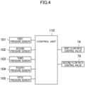
- the compressor (10) includes five pressure sensors (101, 102, 103, 104, 105).
- the first pressure sensor (101) is disposed in the suction pipe (12).
- the first pressure sensor (101) detects the pressure of the suction passage (12a). In other words, the first pressure sensor (101) detects the pressure of the refrigerant introduced into the first compression chamber (61a).
- the first pressure sensor (101) may be disposed near the first inlet (20a) or in the electric motor chamber (28) in the casing (20).
- the second pressure sensor (102) is disposed in the connection pipe (11).
- the second pressure sensor (102) detects the pressure of the communication passage (11a). In other words, the second pressure sensor (102) detects the pressure of the refrigerant introduced into the second compression chamber (66a).
- the second pressure sensor (102) may be disposed near the first outlet (20b) or at the second inlet (20c) in the casing (20).
- the third pressure sensor (103) is disposed in the discharge pipe (13).
- the third pressure sensor (103) detects the pressure of the discharge passage (13a). In other words, the third pressure sensor (103) detects the pressure of the refrigerant discharged from the casing (20).
- the third pressure sensor (103) is disposed near the second outlet (20d) in the casing (20).
- the fourth pressure sensor (104) is disposed in the second hole (92) of the first housing (23).
- the fourth pressure sensor (104) detects the pressure of the second space (S2) of the first back surface space (61b). In other words, the fourth pressure sensor (104) detects the back surface pressure of the first impeller (50a).
- the fourth pressure sensor (104) may be disposed in the first bypass pipe (73). In this case, the fourth pressure sensor (104) is disposed near the inflow end of the first bypass passage (73a) in the first bypass pipe (73).
- the fifth pressure sensor (105) is disposed in the second hole (92) of the second housing (25).
- the fifth pressure sensor (105) detects the pressure of the second space (S2) of the second back surface space (66b). In other words, the fifth pressure sensor (105) detects the back surface pressure of the second impeller (50b).
- the fifth pressure sensor (105) may be disposed in the second bypass pipe (78). In this case, the fifth pressure sensor (105) is disposed near the inflow end of the second bypass passage (78a) in the second bypass pipe (78).
- the control unit (110) controls the operation of the compressor (10).
- the control unit (110) includes a microcomputer and a memory device.
- the memory device stores various programs and data.
- the microcomputer executes the programs read from the memory device.
- the control unit (110) controls the operations of the first flow rate control valve (74) and the second flow rate control valve (79).
- the control unit (110) opens or closes the first flow rate control valve (74) and the second flow rate control valve (79) or adjusts the opening degree of the first flow rate control valve (74) and the second flow rate control valve (79) based on the values detected by the first pressure sensor (101), the second pressure sensor (102), the third pressure sensor (103), the fourth pressure sensor (104), and the fifth pressure sensor (105).
- control unit (110) obtains the values detected by the first to fifth pressure sensors (101, 102, 103, 104, 105).
- the control unit (110) calculates the thrust load acting from both ends of the rotary shaft (40) based on the values detected by the pressure sensors (101, 102, 103, 104, 105).
- the control unit (110) opens or closes the first flow rate control valve (74) and the second flow rate control valve (79) or adjusts the opening degrees of the first flow rate control valve (74) and the second flow rate control valve (79) based on the calculated thrust load.
- each flow rate control valve (74, 79) is opened or closed or the opening degree of each flow rate control valve (74, 79) is adjusted based on the pressure which is a direct index of the thrust load acting on the rotary shaft (40), and thus the flow rate control valve (74, 79) can be controlled according to the actually acting thrust load. Accordingly, the reliability of the compressor (10) can be improved.
- the electric motor (30) When the compressor (10) operates, the electric motor (30) is energized. Accordingly, the rotary shaft (40) rotates.
- the impellers (50a, 50b) coupled to the rotary shaft (40) rotate.
- a low-pressure (suction-pressure) refrigerant flows from the suction pipe (12) into the electric motor chamber (28) through the first inlet (20a).
- the refrigerant having flowed into the electric motor chamber (28) flows into the first compression chamber (61a).
- the blades (53) of the first impeller (50a) sends the refrigerant radially outward, and the flow rate of the refrigerant is made faster. As the speed of this refrigerant is made faster, the pressure of the refrigerant increases.
- the low-pressure refrigerant having flowed into the first compression chamber (61a) is compressed to an intermediate pressure that is higher than the suction pressure.
- the refrigerant having been compressed to the intermediate pressure passes through the diffuser (62) and then flows through the scroll flow path (63).
- the refrigerant having flowed through the scroll flow path (63) passes through the first outlet (20b) and then flows into the communication passage (11a).
- the intermediate-pressure refrigerant having flowed into the communication passage (11a) passes through the second inlet (20c) and then flows into the intermediate-pressure flow path (29).
- the refrigerant having flowed into the intermediate-pressure flow path (29) flows into the second compression chamber (66a).
- the blades (53) of the second impeller (50b) increases the speed of the refrigerant, thereby increasing the pressure of the second compression chamber (66a).
- the refrigerant having flowed into the second compression chamber (66a) is compressed to a high pressure (a discharge pressure) that is higher than the intermediate pressure.
- the refrigerant having been compressed to the discharge pressure passes through the diffuser (67) and then flows through the scroll flow path (68).
- the refrigerant having flowed through the scroll flow path (68) passes through the second outlet (20d) and then flows into the discharge pipe (13).
- the high-pressure refrigerant having flowed into the discharge pipe (13) is sent to the outside of the casing (20).
- the refrigerant having been discharged from the compressor (10) is used for the refrigeration cycle of the refrigeration apparatus (1).
- the thrust loads acting from both sides of the rotary shaft (40) may become unbalanced depending on the operating conditions. Specifically, depending on the operating conditions, the thrust load L2 acting from the second impeller (50b) may be heavier or lighter than the thrust load L 1 acting from the first impeller (50a).
- the first flow rate control valve (74) and the second flow rate control valve (79) are closed when the compressor (10) starts operation.
- FIG. 5 shows an operation area map where the horizontal axis represents an evaporation temperature Te and the vertical axis represents a condensation temperature Tc.
- the areas in gray are operable areas, and the areas in black are inoperable areas.
- FIG. 5 shows that both the first flow rate control valve (74) and the second flow rate control valve (79) are closed, (b) shows that only the first flow rate control valve (74) is opened, (c) shows that only the second flow rate control valve (79) is opened, and (d) shows that both the first flow rate control valve (74) and the second flow rate control valve (79) are opened.
- (e) of FIG. 5 shows a combination of (a) to (d) of FIG 5 , and shows an area where the compressor (10) is operable as a whole. In FIG. 5 , detailed numerical values are omitted.
- the control unit (110) directs the first flow rate control valve (74) to be opened if the thrust load L1 is heavier than the thrust load L2 (L1 > L2).
- the first flow rate control valve (74) is opened, the second space (S2) of the first back surface space (61b) communicates with the suction passage (12a), and the pressure of the second space (S2) is lowered. Accordingly, the pressure acting on the whole of the back surface (52) of the first impeller (50a) becomes relatively low. Accordingly, the thrust load L1 on the first impeller (50a) and the thrust load L2 on the second impeller (50b) can be balanced.
- the flow rate of the refrigerant discharged from the casing (20) to the outside may be adjusted by adjusting the opening degree of each flow rate control valve (74, 79).
- the control unit (110) directs the second flow rate control valve (79) to be opened if the thrust load L2 is heavier than the thrust load L1 (L1 ⁇ L2).
- the second flow rate control valve (79) is opened, the second space (S2) of the second back surface space (66b) communicates with the suction passage (12a), and the pressure of the second space (S2) is lowered. Accordingly, the pressure acting on the whole of the back surface (52) of the second impeller (50b) becomes relatively low. Accordingly, the thrust load L1 on the first impeller (50a) and the thrust load L2 on the second impeller (50b) can be balanced.
- the flow rate of the refrigerant discharged from the casing (20) to the outside may be adjusted by adjusting the opening degree of each flow rate control valve (74, 79).
- the control unit (110) directs the first flow rate control valve (74) and the second flow rate control valve (79) to be opened.
- the second space (S2) of the first back surface space (61b) and the second space (S2) of the second back surface space (66b) both have lower pressures, and thus the balance between the thrust load L1 on the first impeller (50a) and the thrust load L2 on the second impeller (50b) is maintained.
- the flow rate of the refrigerant discharged from the casing (20) to the outside may be adjusted by adjusting the opening degree of each flow rate control valve (74, 79).
- the operable area of the compressor (10) can be changed and made larger.
- the operable area of the compressor (10) as a whole can be made larger.
- the compressor (10) of this embodiment is designed to be most efficient when the first flow rate control valve (74) and the second flow rate control valve (79) are closed under the operation condition (the rated condition) for evaluating the efficiency of the compressor.
- the operating condition (the rated condition) for evaluating the efficiency of the compressor can be said to be an operating condition frequently used as the operating condition of the compressor.
- the frequency of the first flow rate control valve (74) or the second flow rate control valve (79) being opened is relatively low.
- the efficiency of the compressor may decrease.
- the frequency of the first flow rate control valve (74) or the second flow rate control valve (79) being opened is relatively low, and thus the efficiency of the compressor (10) does not decrease so much even if the compressor (10) includes the first decrease element (71) and the second decrease element (76).
- the compressor (10) operates under an operating condition other than the rated condition, the thrust loads acting from both sides of the rotary shaft (40) may become unbalanced depending on the operating condition as described above.
- the first flow rate control valve (74) or the second flow rate control valve (79) the balance between the thrust loads on both sides in the axial direction can be maintained. Accordingly, the load on the thrust bearing (41) under a predetermined operating condition can be reduced, and the upsizing of the thrust bearing (41) can be reduced.
- the flow rate of the refrigerant can be adjusted, and thus the operable area of the compressor (10) can be made larger without upsizing of the thrust bearing (41).
- the compressor (10) of this embodiment includes a pair of impellers (50a, 50b) including their respective front surfaces (51) having blades (53) and facing each other with the electric motor (30) interposed therebetween, and a decrease element (71, 76) configured to reduce a pressure of a back surface space (61b, 66b) of one of the pair of impellers (50a, 50b).
- the pressure of the back surface space (61b, 66b) of one of the impellers (50a, 50b) can be reduced by the decrease element (71, 76), and thus the difference between the pressures acting on the back surfaces (52) of the pair of impellers (50a, 50b) can be reduced. Accordingly, the load on the thrust bearing (41) can be reduced, and thus the upsizing of the thrust bearing (41) can be reduced. As a result, wind loss caused when the rotary shaft (40) rotates at high speed can be reduced. In addition, the upsizing of the thrust bearing (41) can be reduced, and thus a decrease in the rigidity of the whole of the rotary shaft (40) can be reduced. In this manner, a decrease in the mechanical efficiency of the turbo fluid machine (10) can be reduced.
- the compressor (10) of this embodiment further includes a suction passage (12a) configured to introduce a fluid into the casing (20).
- the decrease element (71, 76) includes a seal portion (72, 77) configured to partition the back surface space (61b, 66b) into a first space (S1) and a second space (S2), and a bypass passage (73a, 78a) configured to bypass a fluid in the second space (S2) to the suction passage (12a).
- the first space (S1) has a pressure corresponding to the discharge pressure of the compression chamber (61a, 66a) corresponding to the one of the impellers (50a, 50b).
- the pressure of the second space (S2) is lower than that of the first space (S1).
- the pressure acting on the whole of the back surface (52) of the one of the impellers (50a, 50b) is lower than if the second space (S2) is not formed. Accordingly, the difference between the pressures acting on the back surfaces (52) of the pair of impellers (50a, 50b) can be reduced.
- one of the impellers (50a, 50b) includes a first member (80) that is tubular and extends away in an axial direction from a back surface (52) of the one of the impellers (50a, 50b).
- the casing (20) has a first surface (92) facing an outer circumferential surface of the first member (80).
- the seal portion (72, 77) consists of a clearance (A) between the outer circumferential surface of the first member (80) and the first surface (92). Accordingly, the seal portion (72, 77) can be formed with a small number of components.
- the decrease element (71, 76) further includes a valve (74, 79) disposed in the bypass passage (73a, 78a). Accordingly, the pressure of the second space (S2) can be adjusted by opening or closing the other valve (74, 79) or changing the opening degree of the other valve (74, 79).
- the compressor (10) of this embodiment further includes a control unit (110) configured to control the valve (74, 79).
- the control unit (110) opens or closes the valve (74, 79) or adjusts the opening degree of the valve (74, 79) based on a suction pressure of a fluid introduced into each of the pair of compression chambers (61a, 66a), a discharge pressure of a fluid discharged from the casing (20), and a back surface pressure of one of the impellers (50a, 50b).
- the pair of impellers (50a, 50b) are each provided with the decrease element (71, 76). Accordingly, the pressure of the back surface space (61b, 66b) of each impeller (50a, 50b) can be adjusted under various operating conditions.
- the pair of impellers (50a, 50b) consists of a first impeller (50a) configured to compress a fluid with a suction pressure introduced into the casing (20) to an intermediate pressure that is higher than the suction pressure, and a second impeller (50b) configured to compresses a fluid with an intermediate pressure to a discharge pressure that is higher than the intermediate pressure.
- the outer diameter of the second impeller (50b) is smaller than that of the first impeller (50a). Accordingly, the load acting from the back surface (52) of the second impeller (50b) can be lowered.
- the compressor (10) of this embodiment further includes a bearing (41, 45, 45) disposed in the casing (20) and configured to rotatably support the rotary shaft (40).
- the bearing (41, 45, 45) is a foil bearing or a magnetic bearing.
- the bearing (41, 45, 45) is a foil bearing or a magnetic bearing, i.e., an oil-free bearing.
- the rotary shaft (40) has a maximum number of revolutions of 30,000 rpm or more. Since the rotary shaft (40) has a maximum number of revolutions of 30,000 rpm or more, and thus the turbo fluid machine of this embodiment is applicable as the turbo fluid machine (10) that rotates at a high speed.
- the turbo fluid machine (10) of this embodiment is a turbo compressor.
- the fluid is a refrigerant.
- the pressure acting on the back surface (52) of the impeller (50a, 50b) is higher than if the fluid is air. Accordingly, the thrust load acting on the rotary shaft (40) is heavier.
- the refrigeration apparatus (1) of this embodiment includes a refrigerant circuit (2) that performs a refrigeration cycle.
- the refrigerant circuit (2) includes a turbo compressor (10).
- the refrigeration apparatus (1) of this embodiment has a refrigerating capacity of 100 USRT or less. Since the refrigeration apparatus (1) has a refrigerating capacity of 100 USRT or less, the turbo compressor (10) is applicable to the refrigeration apparatus (1) with a relatively small refrigerating capacity.
- the first seal portion (72) or the second seal portion (77) of the above embodiment may be a labyrinth seal with a labyrinth structure. As shown in FIG. 6 , the seal portion (72, 77) of this variation is an expansion labyrinth seal including an expansion chamber. Note that FIG. 6 is an enlarged view of the second decrease element (76). The first seal portion (72) of the first decrease element (71) may have the same structure as the second seal portion (77) of this variation.
- the second seal portion (77) consists of a clearance (A) between a partition member (80) and the second housing (25).
- the second seal portion (77) consists of a refrigerant flow path (R) and a plurality of expansion chambers (E).
- the second housing (25) of this variation has the same configuration as in the above embodiment.
- the partition member (80) of this variation includes a cylindrical part (81) and a plurality of protrusions (82).
- the cylindrical part (81) has the same configuration as in the above embodiment.
- Each protrusion (82) protrudes radially outward from the outer circumferential surface of the cylindrical part (81).
- Each protrusion (82) is formed in an annular shape surrounding the circumference of the cylindrical part (81).
- the expansion chamber (E) is formed between the protrusions (82).
- the plurality of expansion chambers (E) are arranged at regular intervals in the axial direction.
- each protrusion (82) faces the second hole (92) of the second housing (25).
- a minute clearance is formed between the distal end of each protrusion (82) and the second hole (92) of the second housing (25).
- the minute clearance forms a refrigerant flow path (R).
- the refrigerant flow path (R) extends straight in the axial direction.
- the refrigerant flow path (R) communicates with the plurality of expansion chambers (E).
- the refrigerant flowing from the first space (S1) to the second space (S2) flows along the refrigerant flow path (R).
- the refrigerant expands and is decompressed.
- the refrigerant having flowed out of one of the expansion chambers (E) flows into the refrigerant flow path (R), and then flows into the adjacent expansion chamber (E). In this manner, the refrigerant flows a plurality of times repeatedly from the refrigerant flow path (R) into the expansion chambers (E).
- the first seal portion (72) or the second seal portion (77) of the above embodiment may be a labyrinth seal with another labyrinth structure.
- the seal portion (72, 77) of this variation is a labyrinth seal of a labyrinth type.
- FIG. 7 is an enlarged view of the second decrease element (76).
- the first seal portion (72) of the first decrease element (71) may have the same structure as the second seal portion (77) of this variation.
- the second seal portion (77) consists of a clearance (A) between a partition member (80) and the second housing (25).
- the second seal portion (77) consists of a refrigerant flow path (R).
- the partition member (80) of this variation includes a cylindrical part (81) and a plurality of protrusions (82).
- the cylindrical part (81) has the same configuration as in the above embodiment.
- Each protrusion (82) protrudes radially outward from the outer circumferential surface of the cylindrical part (81).
- Each protrusion (82) is formed in an annular shape surrounding the circumference of the cylindrical part (81).
- the plurality of protrusions (82) are arranged at regular intervals in the axial direction.
- the second housing (25) of this variation includes a second hole (92) provided with a plurality of recesses (94).
- the recess (94) is recessed radially outward.
- the plurality of recesses (94) are arranged at regular intervals in the axial direction.
- the recesses (94) face the protrusions (82) of the partition member (80).
- the protrusions (82) of the partition member (80) are arranged to mesh with their respective recesses (94) of the second housing (25).
- a minute clearance is formed between the protrusion (82) and the recess (94) of the second housing (25). This minute clearance forms a refrigerant flow path (R).
- the refrigerant flow path (R) is bent in a zigzag manner.
- part of the refrigerant in the first space (S1) flows into the refrigerant flow path (R) from a clearance between the second hole (92) of the second housing (25) and the distal end of the protrusion (82) at the left end of the partition member (80).
- the refrigerant having entered the clearance flows radially inward along the right side surface of the protrusion (82) at the left end, and then flows toward the other end in the axial direction along the outer circumferential surface of the cylindrical part (81). Afterward, the refrigerant flows radially outward along the left side surface of another protrusion (82) adjacent thereto.
- the refrigerant flows through the clearance (A) toward the other end in the axial direction, while alternating the direction between the radially inner side and the radially outer side, thereby flowing through a very narrow flow path over a relatively long distance. Accordingly, the flow of the refrigerant from the first space (S1) into the second space (S2) can be reduced.
- the first seal portion (72) or the second seal portion (77) of the above embodiment may be a labyrinth seal with another labyrinth structure.
- the seal portion (72, 77) of this variation is a labyrinth seal of a labyrinth type.
- FIG. 8 is an enlarged view of the second decrease element (76).
- the first seal portion (72) of the first decrease element (71) may have the same structure as the second seal portion (77) of this variation.
- the second seal portion (77) consists of a clearance (A) between a partition member (80) and the second housing (25).
- the second seal portion (77) consists of a refrigerant flow path (R).
- the partition member (80) of this variation includes a cylindrical part (81).
- the cylindrical part (81) extends in the axial direction from the back surface (52) of the second impeller (50b).
- the outer circumferential surface of the cylindrical part (81) has first steps (83).
- the outer diameter of the first steps (83) decreases toward the other end in the axial direction (the right side in FIG. 8 ).
- the inner circumferential surface of the second housing (25) has second steps (95).
- the second steps (95) are formed between the first hole (91) and the second hole (92) in the second housing (25).
- the inner diameter of the second steps (95) decreases toward the other end in the axial direction (the right side in FIG. 8 ).
- the first steps (83) and the second steps (95) correspond to each other.
- a minute clearance is formed between the outer circumferential surface of the first steps (83) and the inner circumferential surface (96) of the second steps (95).
- This minute clearance forms a refrigerant flow path (R).
- the refrigerant flow path (R) is in the form of steps.
- the inner circumferential surface (96) of the second steps (95) corresponds to the first surface of the present disclosure.
- part of the refrigerant in the first space (S1) flows into the refrigerant flow path (R) in the form of steps, that is, passes through a very narrow flow path over a relatively long distance. Accordingly, the flow of the refrigerant from the first space (S1) into the second space (S2) can be reduced.
- the first seal portion (72) or the second seal portion (77) of the above embodiment may be a seal with another structure.
- the seal portion (72, 77) of this variation consists of a clearance (B) between the back surface (52) of the second impeller (50b) and the second housing (25).
- the second impeller (50b) of this variation includes no partition member.
- FIG. 9 is an enlarged view of the second decrease element (76).
- the first seal portion (72) of the first decrease element (71) may have the same structure as the second seal portion (77) of this variation.
- the second housing (25) faces the back surface (52) of the second impeller (50b).
- the second housing (25) corresponds to the wall of the present disclosure.
- the second housing (25) includes a protrusion (97).
- the protrusion (97) protrudes toward the back surface (52) of the second impeller (50b).
- the protrusion (97) is formed in an annular shape to surround the circumference of the through hole formed at the center of the second housing (25).
- the clearance (B) is formed between the back surface (52) of the second impeller (50b) and the end surface (97a) of the protrusion (97) of the second housing (25).
- the seal portion (72, 77) of this variation consists of the clearance (B).
- the seal portion (72, 77) consists of a refrigerant flow path (R) extending straight in the radial direction.
- the space radially outside the protrusion (97) is a first space (S 1).
- S2 In the second back surface space (66b), the space radially inside the protrusion (97) is a second space (S2).
- the refrigerant flow path (R) of this embodiment is very narrow, and thus, when the refrigerant flows from the first space (S 1) into the refrigerant flow path (R), the narrow flow path serves as a resistance and functions as a seal.
- the decrease element (71, 76) of the above embodiment may include an on-off valve instead of the flow rate control valve (74, 79).
- the valve may not necessarily adjust the flow rate.
- the pressure of the second space (S2) can be changed by changing the opening and closing of the on-off valve.
- the decrease element (71, 76) of the above embodiment may include the seal portion (72, 77) and the bypass passage (73a, 78a). In other words, the decrease element (71, 76) may not necessarily have a valve.
- the compressor (10) of the above embodiment may include any one of the first decrease element (71) and the second decrease element (76). In other words, the compressor (10) may not necessarily include both the first decrease element (71) and the second decrease element (76).
- the compressor (10) includes the first decrease element (71) only, the compressor (10) does not include the fifth pressure sensor (105).
- the control unit (110) opens or closes the first flow rate control valve (74) or adjusts or the opening degree of the first flow rate control valve (74) based on the values detected by the first pressure sensor (101), the second pressure sensor (102), the third pressure sensor (103), and the fourth pressure sensor (104).
- the compressor (10) does not include the fourth pressure sensor (104).
- the control unit (110) opens or closes the second flow rate control valve (79) or adjusts the opening degree of the second flow rate control valve (79) based on the values detected by the first pressure sensor (101), the second pressure sensor (102), the third pressure sensor (103), and the fifth pressure sensor (105).
- the control unit (110) of the above embodiment may open or close the first flow rate control valve (74) and the second flow rate control valve (79) or adjust the opening degrees of the first flow rate control valve (74) and the second flow rate control valve (79) based on the temperature of the refrigerant.
- the above embodiment may also be configured as follows.
- the decrease element (71, 76) of the above embodiment may be a screw provided on the back surface of the impeller (50a, 50b).
- the screw is fixed to the central portion of the back surface of the impeller (50a, 50b) and rotates integrally with the rotary shaft (40).
- the blades of the screw are provided so as to release the pressure of the back surface space (61b, 66b) of the impeller (50a, 50b) to the outside according to the rotation. Accordingly, the pressure at the portion provided with the screw decreases according to the rotation of the screw, and thus the pressure acting on the whole of the back surface (52) of the impeller (50a, 50b) can be lowered.
- the communication passage (11a) of the above embodiment may be a path formed in the casing (20) instead of the connection pipe (11).
- the turbo fluid machine of the above embodiment may be a pump (e.g., a centrifugal pump) instead of the turbo compressor (10).
- a liquid is used as the fluid.
- the present disclosure is useful for a turbo fluid machine and a refrigeration apparatus.
Landscapes
- Engineering & Computer Science (AREA)
- Mechanical Engineering (AREA)
- General Engineering & Computer Science (AREA)
- Structures Of Non-Positive Displacement Pumps (AREA)
Abstract
Description
- The present disclosure relates to a turbo fluid machine and a refrigeration apparatus.
-
Patent Document 1 discloses a turbo compressor including a hermetically closed container that houses a drive motor, a drive shaft, and two impellers. The drive motor is disposed in a motor chamber at a central portion of the hermetically closed container. The drive shaft is inserted into the drive motor and has two ends, one of which is inserted into a first compression chamber and the other one of which is inserted into a second compression chamber. The impellers are disposed on both ends of the drive shaft. The two impellers are arranged with their front surfaces facing each other. - In the turbo compressor of
Patent Document 1, the gas having flown into the electric motor chamber is sucked into the first compression chamber where one of the impellers is disposed and is subjected to primary compression therein. The gas having undergone the primary compression is sucked into the second compression chamber where the other one of the impellers is disposed and is subjected to secondary compression therein. - In the turbo compressor of
Patent Document 1, the two impellers are arranged with their front surfaces facing each other, and thus, by sealing the gap between the electric motor chamber and the second compression chamber, the gas having undergone the primary compression is less likely to leak into the electric motor chamber. In this manner, by reducing the number of passages through which the compressed gas leaks, the volumetric efficiency is improved, and thus the efficiency of the compressor is improved. - Patent Document 1:
Japanese Unexamined Patent Publication No. H11-230098 - In the turbo fluid machine as disclosed in
Patent Document 1, the two impellers are arranged with their front surfaces facing each other, and thus the pressure of the gas compressed in each compression chamber acts on the whole of the back surface of each impeller. If the difference in pressure acting on the back surfaces of the impellers becomes larger depending on the operating conditions of the compressor, the thrust load acting from one of the impellers and the thrust load acting from the other one of the impellers become unbalanced, and the thrust bearing on the drive shaft receives a heavy load. In order to deal with such a load, it is necessary to provide a larger thrust bearing. - However, if the thrust bearing is upsized, friction occurs between the drive shaft and the gas in the hermetically closed container when the drive shaft rotates at a high speed, and thus wind loss increases. If wind loss increases, the efficiency of the compressor decreases. In addition, if the thrust bearing is upsized, the rigidity of the whole of the drive shaft become lowered. Accordingly, the number of revolutions at which the compressor can operate at high speed is limited, and the range of operation of the compressor is reduced. In this manner, if the thrust bearing is upsized, the mechanical efficiency of the turbo fluid machine disadvantageously decreases.
- An object of the present disclosure is to reduce the decrease in the mechanical efficiency.
- A first aspect is directed to a turbo fluid machine configured to compress an introduced fluid with a suction pressure to an intermediate pressure that is higher than the suction pressure, and then compress the fluid with the intermediate pressure to a discharge pressure that is higher than the intermediate pressure. The turbo fluid machine includes: a rotary shaft (40); an electric motor (30) configured to drive the rotary shaft (40); a pair of impellers (50a, 50b) that are configured to rotate integrally with the rotary shaft (40) to compress a fluid sucked into compression chambers (61a, 66a), and that include front surfaces (51) provided with blades (53) and facing each other with the electric motor (30) interposed therebetween; a casing (20) including the compression chambers (61a, 66a) corresponding to the pair of impellers (50a, 50b), respectively; a communication passage (11a) communicating the pair of compression chambers (61a, 66a) with each other; and a decrease element (71, 76) configured to reduce a pressure of a back surface space (61b, 66b) of one of the pair of impellers (50a, 50b).
- According to the first aspect, the pressure of the back surface space (61b, 66b) of one of the impellers (50a, 50b) can be reduced by the decrease element (71, 76), and thus the difference between the pressures acting on the back surfaces (52) of the pair of impellers (50a, 50b) can be reduced. Accordingly, the upsizing of the thrust bearing can be reduced. As a result, a decrease in the mechanical efficiency of the turbo fluid machine (10) can be reduced.
- A second aspect is an embodiment of the first aspect. In the second aspect, the turbo fluid machine further includes a suction passage (12a) configured to introduce a fluid into the casing (20), wherein the decrease element (71, 76) includes a seal portion (72, 77) configured to partition the back surface space (61b, 66b) into a first space (S1) and a second space (S2), and a bypass passage (73a, 78a) configured to bypass a fluid in the second space (S2) to the suction passage (12a); the first space (S1) has a pressure corresponding to the discharge pressure of the compression chamber (61a, 66a) corresponding to the one of the impellers (50a, 50b); and a pressure of the second space (S2) is lower than the pressure of the first space (S1).
- According to the second aspect, the bypass passage (73a, 78a) enables the second space (S2) to have a pressure corresponding to the suction pressure, and the pressure of the second space (S2) is lower than that of the first space (S1). Accordingly, the pressure acting on the whole of the back surface (52) of the one of the impellers (50a, 50b) is lower than if the second space (S2) is not formed. Accordingly, the difference between the pressures acting on the back surfaces (52) of the pair of impellers (50a, 50b) can be reduced.
- A third aspect is an embodiment of the second aspect. In the third aspect, the one of the impellers (50a, 50b) includes a first member (80) that is tubular and extends away in an axial direction from a back surface (52) of the one of the impellers (50a, 50b), the casing (20) has a first surface (92, 96) facing an outer circumferential surface of the first member (80), and the seal portion (72, 77) consists of a clearance (A) between the outer circumferential surface of the first member (80) and the first surface (92, 96).
- According to the third aspect, the seal portion (72, 77) consists of the clearance (A) between the first member (80) of the one of the impellers (50a, 50b) and the first surface (92, 96) of the casing (20), and thus the seal portion (72, 77) can be provided with a small number of additional components.
- A fourth aspect is an embodiment of the second aspect. In the fourth aspect, the casing (20) includes a wall (25) facing a back surface (52) of the one of the impellers (50a, 50b), the wall (25) has a protrusion (97) that is annular and protrudes toward the back surface (52) of the one of the impellers (50a, 50b), and the seal portion (72, 77) consists of a clearance (B) between the back surface (52) of the one of the impellers (50a, 50b) and an end surface (97a) of the protrusion (97).
- According to the fourth aspect, the clearance (B) is formed between the back surface (52) of the one of the impellers (50a, 50b) and the end surface (97a) of the protrusion (97) of the casing (20). The seal portion (72, 77) consists of the clearance (B), and thus the seal portion (72, 77) can be formed without any new additional components.
- A fifth aspect is an embodiment of any one of the second to fourth aspects. In the fifth aspect, the decrease element (71, 76) further includes a valve (74, 79) in the bypass passage (73a, 78a).
- According to the fifth aspect, the pressure of the second space (S2) can be adjusted by opening or closing the valve (74, 79) or changing the opening degree of the valve (74, 79).
- A sixth aspect is an embodiment of the fifth aspect. In the sixth aspect, the turbo fluid machine further includes a control unit (110) configured to control the valve (74, 79), wherein the control unit (110) is configured to open or close the valve (74, 79) or adjust an opening degree of the valve (74, 79) based on a suction pressure of a fluid introduced into each of the pair of compression chambers (61a, 66a), a discharge pressure of a fluid discharged from the casing (20), and a back surface pressure of the one of the impellers (50a, 50b).
- According to the sixth aspect, the control unit (110) opens or closes the valve (74, 79) or adjusts the opening degree of the valve (74, 79) based on the pressure which is a direct index of the thrust load acting on the rotary shaft (40), and thus the reliability of the turbo fluid machine (10) can be improved.
- A seventh aspect is an embodiment of any one of the first to sixth aspects. In the seventh aspect, each of the pair of impellers (50a, 50b) is provided with the decrease element (71, 76).
- According to the seventh aspect, each of the pair of impellers (50a, 50b) is provided with the decrease element (71, 76), and thus the pressure of the back surface space (61b, 66b) of each impeller (50a, 50b) can be adjusted under various operating conditions.
- An eighth aspect is an embodiment of any one of the first to seventh aspects. In the eighth aspect, the pair of impellers (50a, 50b) includes a first impeller (50a) configured to compress a fluid with a suction pressure introduced into the casing (20) to an intermediate pressure that is higher than the suction pressure, and a second impeller (50b) configured to compress a fluid with the intermediate pressure to a discharge pressure that is higher than the intermediate pressure; and an outer diameter of the second impeller (50b) is smaller than an outer diameter of the first impeller (50a).
- According to the eighth aspect, the outer diameter of the second impeller (50b) is smaller than that of the first impeller (50a), and thus the load acting from the back surface (52) of the second impeller (50b) can be reduced.
- A ninth aspect is an embodiment of any one of the first to eighth aspects. In the ninth aspect, the turbo fluid machine further includes a bearing (41, 45, 45) disposed in the casing (20) and configured to rotatably support the rotary shaft (40), wherein the bearing (41, 45, 45) is a foil bearing or a magnetic bearing.
- According to the ninth aspect, the bearing (41, 45, 45) is a foil bearing or a magnetic bearing, i.e., an oil-free bearing.
- A tenth aspect is an embodiment of any one of the first to ninth aspects. In the tenth aspect, the rotary shaft (40) has a maximum number of revolutions of 30,000 rpm or more.
- According to the tenth aspect, the rotary shaft (40) has a maximum number of revolutions of 30,000 rpm or more, and thus the turbo fluid machine of this aspect is applicable as the turbo fluid machine (10) that rotates at a high speed.
- An eleventh aspect is an embodiment of any one of the first to tenth aspects. In the eleventh aspect, the turbo fluid machine is a turbo compressor (10), and the fluid is a refrigerant.
- In the eleventh aspect, the fluid is a refrigerant. Here, if the fluid is a refrigerant, the pressure acting on the back surface (52) of the impeller (50a, 50b) is higher than if the fluid is air. Accordingly, the thrust load acting on the rotary shaft (40) is heavier.
- A twelfth aspect is directed to a refrigeration apparatus including a refrigerant circuit (2) configured to perform a refrigeration cycle. The refrigerant circuit (2) includes the turbo fluid machine of the eleventh aspect.
- A thirteenth aspect is an embodiment of the twelfth aspect. In the thirteenth aspect, the refrigeration apparatus has a refrigerating capacity of 100 American tons of refrigeration (USRT) or less.
- According to the thirteenth aspect, having a refrigerating capacity of 100 USRT or less, the turbo compressor is applicable to a refrigeration apparatus with a relatively small refrigerating capacity.
-
-
FIG. 1 is a schematic configuration diagram of a refrigeration apparatus of an embodiment. -
FIG. 2 is a schematic longitudinal sectional view showing an overall configuration of a turbo compressor. -
FIG. 3 is an enlarged view within the frame III inFIG. 2 . -
FIG. 4 is a block diagram of the turbo compressor. -
FIG. 5 shows an operation area map of the turbo compressor. -
FIG. 6 corresponds toFIG. 3 and illustrates a first variation. -
FIG. 7 corresponds toFIG. 3 and illustrates a second variation. -
FIG. 8 corresponds toFIG. 3 and illustrates a third variation. -
FIG. 9 corresponds toFIG. 3 and illustrates a fourth variation. - An embodiment of the present disclosure will be described in detail below with reference to the drawings. The present disclosure is not limited to the embodiment shown below, and various changes can be made within the scope without departing from the technical concept of the present disclosure. Since each of the drawings is intended to illustrate the present disclosure conceptually, dimensions, ratios, or numbers may be exaggerated or simplified as necessary for the sake of ease of understanding.
- A turbo fluid machine of an embodiment will be described. The turbo fluid machine of this embodiment is a turbo compressor (10). The turbo compressor (10) (hereinafter referred to as a "compressor") is provided in a refrigeration apparatus (1).
- As shown in
FIG. 1 , the refrigeration apparatus (1) includes a refrigerant circuit (2). The refrigerant circuit (2) is filled with a refrigerant. A fluid compressed by the compressor (10) of this example is a refrigerant. For example, the refrigerant is a hydro fluoro carbon (HFC) refrigerant such as R32, a hydro fluoro olefin (HFO) refrigerant such as R1234yf, a natural refrigerant containing HC such as propane, or a mixed refrigerant thereof such as R454C (a mixed refrigerant of R32 and R1234yf). - The refrigerant circuit (2) includes the compressor (10), a radiator (or a condenser) (3), a decompression mechanism (4), and an evaporator (5). The compressor (10), the radiator (3), the decompression mechanism (4), and the evaporator (5) are connected in series by pipes. The decompression mechanism (4) is an expansion valve, for example. The refrigerant circuit (2) circulates the refrigerant to perform a vapor compression refrigeration cycle.
- In the refrigeration cycle, the refrigerant compressed by the compressor (10) dissipates heat to air in the radiator (3). At this time, the refrigerant is liquefied. The refrigerant having dissipated heat is decompressed by the decompression mechanism (4). The decompressed refrigerant is evaporated in the evaporator (5). The evaporated refrigerant is sucked into the compressor (10). The compressor (10) compresses the sucked refrigerant.
- The refrigeration apparatus (1) is an air conditioner, for example. The air conditioner may be a cooling and heating machine that switches between cooling and heating. In this case, the air conditioner has a switching mechanism configured to switch the direction of circulation of the refrigerant. The switching mechanism is a four-way switching valve, for example. The air conditioner may be a device for cooling only or a device for heating only.
- The refrigeration apparatus (1) may be a water heater, a chiller unit, or a cooling apparatus configured to cool air in an internal space. The cooling apparatus is for cooling the air inside a refrigerator, a freezer, or a container, for example.
- The refrigeration apparatus (1) of this embodiment has a refrigerating capacity of 100 American tons of refrigeration (USRT) or less. In other words, the refrigeration apparatus (1) of this embodiment is a refrigeration apparatus having a relatively small refrigerating capacity.
- The compressor (10) sucks a low-pressure gas refrigerant and compresses the sucked gas refrigerant. The compressor (10) discharges the compressed high-pressure gas refrigerant. The compressor (10) of this embodiment is a two-stage compressor that compresses the refrigerant in two stages.
- In the following description, the direction along the axis of a rotary shaft (40) of the compressor (10) will be referred to as an "axial direction," the direction perpendicular to the axial direction as a "radial direction," and the direction along the periphery of the rotary shaft (40) as a "circumferential direction."
- In this embodiment, the rotary shaft (40) has a maximum number of revolutions of 30,000 rpm or more. The maximum number of revolutions defines the maximum value of the number of revolutions of an electric motor (30). It is preferred to increase the maximum number of revolutions of the rotary shaft (40) in the compressor (10) in order to increase the amount of circulation of the refrigerant in the refrigerant circuit (2) and ensure the maximum amount of circulation of the refrigerant. This is advantageous in increasing the cooling capacity in a cooling operation and the heating capacity in a heating operation.
- As shown in
FIG. 2 , the compressor (10) includes a casing (20), the electric motor (30), the rotary shaft (40), bearings (41, 45, 45), and a pair of impellers (50a, 50b). The electric motor (30), the rotary shaft (40), the bearings (41, 45, 45), and the pair of impellers (50a, 50b) are housed in the casing (20). The compressor (10) further includes a connection pipe (11). The connection pipe (11) is provided outside the casing (20). The compressor (10) further includes a decrease element (71, 76). - As shown in
FIG. 2 , the casing (20) is a substantially cylindrical and hermetically closed container with both ends hermetically closed. The casing (20) is disposed with its center line being substantially horizontal. The casing (20) has a barrel (21), a first closing portion (22), and a second closing portion (24). The barrel (21) is substantially in the shape of a cylinder with both ends in an axial direction being opened. The barrel (21) extends in the axial direction. - The first closing portion (22) closes the opening of the barrel (21) at one end in the axial direction (i.e., on the left side in
FIG. 2 ). The first closing portion (22) is formed in a thick cylindrical shape. The first closing portion (22) includes a first housing (23). The first housing (23) is fitted into a hole (22a) at one end of the first closing portion (22) in the axial direction (i.e., at the left end inFIG. 2 ). The first housing (23) is formed in a thick cylindrical shape. The first housing (23) is oriented such that its axis coincides with the axis of the first closing portion (22). - The second closing portion (24) closes the opening of the barrel (21) at the other end in the axial direction (i.e., on the right side in
FIG. 2 ). The second closing portion (24) is formed in a thick cylindrical shape. The second closing portion (24) includes a second housing (25). The second housing (25) is fitted into a hole (24a) at the other end of the first closing portion (22) in the axial direction (i.e., the right end inFIG. 2 ). The second housing (25) is formed in a thick cylindrical shape. The second housing (25) is oriented such that its axis coincides with the axis of the second closing portion (24). - The casing (20) includes a partition wall (26). The partition wall (26) is disposed inside the barrel (21). The partition wall (26) is disposed at the other end of the barrel (21) in the axial direction. In other words, the partition wall (26) is disposed closer to the second closing portion (24) of the barrel (21). The partition wall (26) has an insertion hole (26a) at its central portion. The rotary shaft (40) is inserted into the insertion hole (26a). The partition wall (26) partitions the internal space (27) of the barrel (21) into an electric motor chamber (28) and an intermediate-pressure flow path (29).
- The electric motor chamber (28) is closer to one end in the axial direction (i.e., the left side in
FIG. 2 ) than the partition wall (26) in the internal space (27). The electric motor chamber (28) is formed between the first closing portion (22) and the partition wall (26) in the internal space (27). The intermediate-pressure flow path (29) is closer to the other end in the axial direction (i.e., the right side inFIG. 2 ) than the partition wall (26) in the internal space (27). The intermediate-pressure flow path (29) is formed between the second closing portion (24) and the partition wall (26) in the internal space (27). - The inside of the first closing portion (22) has a first impeller chamber (61), a diffuser (62), and a scroll flow path (63). The first impeller chamber (61) is a space formed in a substantially conical shape. The first impeller chamber (61) communicates with the electric motor chamber (28). The diffuser (62) is formed on the outer periphery of the first impeller chamber (61) in the first closing portion (22). The diffuser (62) is formed in an annular shape between the first impeller chamber (61) and the scroll flow path (63). The diffuser (62) allows the first impeller chamber (61) to communicate with the scroll flow path (63). The scroll flow path (63) is formed spirally around the diffuser (62).
- As shown in
FIGS. 2 and3 , the inside of the second closing portion (24) has a second impeller chamber (66), a diffuser (67), and a scroll flow path (68). The second impeller chamber (66) is a space formed in a substantially conical shape. The second impeller chamber (66) communicates with the intermediate-pressure flow path (29). The diffuser (67) is formed on the outer periphery of the second impeller chamber (66) in the second closing portion (24). The diffuser (67) is formed in an annular shape between the second impeller chamber (66) and the scroll flow path (68). The diffuser (67) allows the second impeller chamber (66) to communicate with the scroll flow path (68). The scroll flow path (68) is formed spirally around the diffuser (67). - The casing (20) includes a first inlet (20a), a first outlet (20b), a second inlet (20c), and a second outlet (20d). The first inlet (20a) is positioned closer to the first closing portion (22) in the axial direction of the barrel (21). The first inlet (20a) communicates with the electric motor chamber (28). The first inlet (20a) is connected with a suction pipe (12). The inside of the suction pipe (12) has a suction passage (12a). The first outlet (20b) is formed at the outer end of the scroll flow path (63) of the first closing portion (22). The first outlet (20b) communicates with the scroll flow path (63). The first outlet (20b) is connected with the connection pipe (11).
- The second inlet (20c) is formed at the end closer to the second closing portion (24) in the axial direction of the barrel (21). The second inlet (20c) communicates with the intermediate-pressure flow path (29). The second inlet (20c) is connected with the connection pipe (11). The second outlet (20d) is formed at the outer end of the scroll flow path (68) of the second closing portion (24). The second outlet (20d) communicates with the scroll flow path (68). The second outlet (20d) is connected with a discharge pipe (13). The inside of the discharge pipe (13) has a discharge passage (13a).
- The connection pipe (11) connects the first outlet (20b) and the second inlet (20c) of the casing (20). The connection pipe (11) allows the first outlet (20b) to communicate with the second inlet (20c). The inside of the connection pipe (11) has a communication passage (11a). The communication passage (11a) has an inflow end connected to the first outlet (20b). The communication passage (11a) has an outflow end connected to the second inlet (20c). The communication passage (11a) allows the first impeller chamber (61) and the second impeller chamber (66) to communicate with each other.
- The electric motor (30) rotationally drives the rotary shaft (40). As shown in
FIG. 2 , the electric motor (30) is housed in the barrel (21). The electric motor (30) is disposed substantially in an intermediate portion of the barrel (21) in the axial direction. The electric motor (30) includes a stator (31) and a rotor (32). The stator (31) is formed in a cylindrical shape. The stator (31) is fixed to the inner circumferential surface of the barrel (21). The rotor (32) is formed in a cylindrical shape. The rotor (32) is disposed inside the stator (31) in the radial direction. The rotor (32) is fixed to the outer circumferential surface of the rotary shaft (40). - The operation frequency (i.e., the number of revolutions) of the electric motor (30) is adjusted by the inverter device. The compressor (10) is of an inverter type with a variable number of rotations. Thus, the number of rotations of the electric motor (30) changes between a low speed and a high speed.
- As shown in
FIG. 2 , the rotary shaft (40) extends from one end to the other end of the barrel (21) of the casing (20) along the center line of the casing (20). The rotary shaft (40) extends in the horizontal direction. - The rotary shaft (40) of this embodiment includes a thrust plate (40a). The thrust plate (40a) is fixed to the rotary shaft (40) at a point closer to the second closing portion (24) than the electric motor (30). The thrust plate (40a) is formed in a disk shape. The thrust plate (40a) extends radially outward from the rotary shaft (40). In this embodiment, the thrust plate (40a) is formed as a component separate from the rotary shaft (40). The thrust plate (40a) may be integral with the rotary shaft (40).
- The compressor (10) includes a thrust bearing (41) and a pair of radial bearings (45, 45) as the bearings (41, 45, 45).
- The thrust bearing (41) is disposed closer to the other end in the axial direction than the electric motor (30) in the electric motor chamber (28). The thrust bearing (41) is an oil-free bearing. The thrust bearing (41) of this embodiment is a magnetic bearing. The thrust bearing (41) levitates the thrust plate (40a) of the rotary shaft (40) by means of the electromagnetic force and rotatably supports the thrust plate (40a) in a non-contact manner. The thrust bearing (41) receives the thrust load acting in the axial direction of the rotary shaft (40). The thrust bearing (41) is attached to the partition wall (26) of the casing (20).
- The thrust bearing (41) includes a pair of electromagnets (42). Each of the pair of electromagnets (42) is formed in an annular shape. The pair of electromagnets (42) face each other with the thrust plate (40a) of the rotary shaft (40) interposed therebetween. Each electromagnet (42) is spaced apart from the thrust plate (40a).
- Radial bearings (45) are disposed at both ends of the electric motor (30) in the electric motor chamber (28). The radial bearings (45) are held by a holding member (not shown) in the barrel (21) of the casing (20). The holding member is fixed to the inner wall of the barrel (21).
- The radial bearings (45) rotatably support the rotary shaft (40). The radial bearings (45) are arranged on the outer circumference of the rotary shaft (40). The radial bearings (45) are oil-free bearings. The radial bearings (45) of this embodiment are foil bearings. Each radial bearing (45) forms a gas film between the radial bearing (45) and the rotary shaft (40), thereby levitating the rotary shaft (40) by means of the gas film and rotatably supporting the rotary shaft (40) in a non-contact manner. The radial bearings (45) receive the radial loads acting radially outside the rotary shaft (40). Each radial bearing (45) includes a bearing housing, a top foil, and a back foil.
- The thrust bearing (41) may be a foil bearing. The radial bearings (45) may be magnetic bearings.
- As shown in
FIG. 2 , the compressor (10) includes the pair of impellers (50a, 50b). The pair of impellers (50a, 50b) include a first impeller (50a) and a second impeller (50b). InFIG. 2 , the outer circumferential surfaces of the impellers (50a, 50b) are shown for easier understanding of the figure. In other words,FIG. 2 does not show the cross-sections of the impellers (50a, 50b). - The first impeller (50a) is housed in the first impeller chamber (61). The first impeller (50a) is connected with one end of the rotary shaft (40) (i.e., the left end in
FIG. 2 ). The second impeller (50b) is housed in the second impeller chamber (66). The second impeller (50b) is connected with the other end of the rotary shaft (40) (i.e., the right end inFIG. 2 ). The impellers (50a, 50b) rotate integrally with the rotary shaft (40) to pump the refrigerant. - Each of the impellers (50a, 50b) is formed in a substantially conical shape. As shown in
FIG. 3 , each impeller (50a, 50b) has a front surface (51) and a back surface (52). The back surface (52) is opposite to the front surface (51) in the axial direction. The front surface (51) of each impeller (50a, 50b) is provided with a plurality of blades (53). As shown inFIG. 2 , the pair of impellers (50a, 50b) are arranged with their respective front surfaces (51) facing each other with the electric motor (30) interposed therebetween. The outer diameter D2 of the second impeller (50b) of this embodiment is smaller than the outer diameter D1 of the first impeller (50a) (D1 > D2). - The first impeller chamber (61) includes a first compression chamber (61a) and a first back surface space (61b). In the first compression chamber (61a), the refrigerant having flowed into the first compression chamber (61a) is compressed by the blades (53) of the first impeller (50a). The first compression chamber (61a) is formed closer to the front surface (51) of the first impeller (50a) in the first impeller chamber (61). Specifically, the first compression chamber (61a) is formed between the front surface (51) of the first impeller (50a) and the interior surface of the first closing portion (22).
- The first back surface space (61b) is formed closer to the back surface (52) of the first impeller (50a) in the first impeller chamber (61). Specifically, the first back surface space (61b) is formed between the back surface (52) of the first impeller (50a) and the interior surface of the first housing (23). The suction side of the first compression chamber (61a) communicates with the electric motor chamber (28). The discharge side of the first compression chamber (61a) communicates with the first back surface space (61b). The discharge side of the first compression chamber (61a) communicate with the diffuser (62).
- The second impeller chamber (66) includes a second compression chamber (66a) and a second back surface space (66b). In the second compression chamber (66a), the refrigerant having flowed into the second compression chamber (66a) is compressed by the blades (53) of the second impeller (50b). The second compression chamber (66a) is formed closer to the front surface (51) of the second impeller (50b) in the second impeller chamber (66). Specifically, the second compression chamber (66a) is formed between the front surface (51) of the second impeller (50b) and the interior surface of the second closing portion (24).
- The second back surface space (66b) is formed closer to the back surface (52) of the second impeller (50b) in the second impeller chamber (66). Specifically, the second back surface space (66b) is formed between the back surface (52) of the second impeller (50b) and the interior surface of the second housing (25). The suction side of the second compression chamber (66a) communicates with the intermediate-pressure flow path (29). The discharge side of the second compression chamber (66a) communicates with the second back surface space (66b). The discharge side of the second compression chamber (66a) communicates with the diffuser (67).
- In the first compression chamber (61a), the first impeller (50a) compresses the refrigerant with a suction pressure (a low pressure) introduced into the casing (20) to an intermediate pressure that is higher than the suction pressure. The refrigerant at the intermediate pressure discharged from the first compression chamber (61a) passes through the diffuser (62), the scroll flow path (63), the communication passage (1 1a), and the intermediate-pressure flow path (29), and then flows into the second compression chamber (66a). At the same time, the intermediate-pressure refrigerant discharged from the first compression chamber (61a) flows into the first back surface space (61b).
- In the second compression chamber (66a), the second impeller (50b) compresses the intermediate-pressure refrigerant to a discharge pressure (a high pressure) that is higher than the intermediate pressure. The discharge-pressure refrigerant discharged from the second compression chamber (66a) passes through the diffuser (67) and the scroll flow path (68) and then flows into the discharge passage (13a). At the same time, the refrigerant with the discharge pressure discharged from the second compression chamber (66a) flows into the second back surface space (66b).
- Here, the pair of impellers (50a, 50b) of this embodiment are arranged with their front surfaces (51) facing each other with the electric motor (30) interposed therebetween. Accordingly, the refrigerant discharged from each compression chamber (61a, 66a) flows into the back surface space (61b, 66b) corresponding to the compression chamber (61a, 66a), and the pressure of the back surface space (61b, 66b) acts on the whole of the back surface (52) of the impeller (50a,50b) corresponding to the compression chamber (61a, 66a).
- Specifically, the discharge side of the first compression chamber (61a) communicates with the first back surface space (61b), and thus the first back surface space (61b) has an intermediate pressure. On the other hand, the discharge side of the second compression chamber (66a) communicates with the second back surface space (66b), and thus the second back surface space (66b) has a high pressure. Accordingly, the pressure P2 acting on the back surface (52) of the second impeller (50b) is higher than the pressure P1 acting on the back surface (52) of the first impeller (50a) (P1 < P2).
- The thrust load L acting on one side of the rotary shaft (40) is calculated by multiplying the back surface area Z of the impeller on one side by the pressure P acting on the back surface of the impeller (L = Z × P). Thus, if the back surface area Z1 of the first impeller (50a) and the back surface area Z2 of the second impeller (50b) are the same, the thrust load L2 acting from the second impeller (50b) becomes heavier than the thrust load L1 acting from the first impeller (50a) (L1 < L2), and the thrust loads acting from both sides of the rotary shaft (40) are not balanced. If the thrust loads on both sides are not balanced, the load on the thrust bearing (41) increases.
- By contrast, in this embodiment as described above, the outer diameter D2 of the second impeller (50b) is smaller than the outer diameter D1 of the first impeller (50a) (D1 > D2). With the outer diameter D2 of the second impeller (50b) smaller than the outer diameter D1 of the first impeller (50a), the back surface area Z2 of the second impeller (50b) becomes smaller than the back surface area Z1 of the first impeller (50a) (Z1 > Z2). Accordingly, the thrust load L1 from the first impeller (50a) and the thrust load L2 from the second impeller (50b) can be easily balanced.
- The height of the blades of each impeller depends on the diameter of the impeller. Specifically, if the impeller has a larger diameter, the blades have a lower height, and if the impeller has a smaller diameter, the blades have a higher height. In this embodiment, the outer diameter D2 of the second impeller (50b) is smaller than the outer diameter D1 of the first impeller (50a) (D1 > D2), and thus the height of the blades (53) of the second impeller (50b) can be greater than that of the blades (53) of the first impeller (50a). By making the height of the blades (53) of the second impeller (50b) relatively high, the clearance between the second closing portion (24) and the blades (53) of the second impeller (50b) can be relatively small in the second compression chamber (66a). Accordingly, the leakage of the refrigerant compressed in the second compression chamber (66a) through the clearance can be reduced, and the compression efficiency is improved.
- The decrease element (71, 76) reduces the pressure of the back surface space (61b, 66b) of one of the pair of impellers (50a, 50b). In this embodiment, each of the pair of impellers (50a, 50b) is provided with the respective decrease element (71, 76). Specifically, the compressor (10) includes a first decrease element (71) provided in the first impeller (50a) and a second decrease element (76) provided in the second impeller (50b).
- As shown in
FIG. 2 , the first decrease element (71) includes a first seal portion (72), a first bypass passage (73a), and a first flow rate control valve (74). The second decrease element (76) includes a second seal portion (77), a second bypass passage (78a), and a second flow rate control valve (79). The flow rate control valve (74, 79) corresponds to the valve of the present disclosure. - Here, the first decrease element (71) and the second decrease element (76) of this embodiment have the same structure. In the following description, the second decrease element (76) will be described as an example with reference to
FIG. 3 . InFIG. 2 , the same reference characters represent the same components of the first decrease element (71) and the second decrease element (76). - As shown in
FIG. 3 , the second seal portion (77) partitions the second back surface space (66b) into a first space (S1) and a second space (S2). In other words, the second seal portion (77) seals the gap between the first space (S1) and the second space (S2). The second seal portion (77) consists of a clearance (A) between a partition member (80) and the second housing (25). The partition member (80) corresponds to the first member of the present disclosure. - The partition member (80) is provided on the back surface (52) of the second impeller (50b). The partition member (80) is disposed in the second back surface space (66b). The partition member (80) of this embodiment includes a cylindrical part (81). The cylindrical part (81) is formed in a cylindrical shape. The cylindrical part (81) extends from the back surface (52) of the second impeller (50b) toward the other end in the axial direction (i.e., the right side in
FIG. 3 ). In other words, the cylindrical part (81) extends away from the back surface (52) of the second impeller (50b) in the axial direction. The cylindrical part (81) is disposed at a central portion of the back surface (52) of the second impeller (50b). The axis of the cylindrical part (81) substantially coincides with the axis of the rotary shaft (40). - The second housing (25) has a central portion including a first hole (91) and a second hole (92). The first hole (91) and the second hole (92) extend in the axial direction. The axis of the second housing (25), the center of the first hole (91), and the center of the second hole (92) substantially coincide with each other. The first hole (91) and the second hole (92) are formed continuously.
- The first hole (91) is formed at one end of the second housing (25) in the axial direction (the left end in
FIG. 3 ). The second hole (92) is formed at the other end of the second housing (25) in the axial direction (the right end inFIG. 3 ). The diameter of the first hole (91) is larger than that of the second hole (92). The length of the first hole (91) is shorter in the axial direction than that of the second hole (92). - An end of the cylindrical part (81) of the partition member (80) is inserted into the second hole (92). A minute cylindrical clearance is formed between the second hole (92) and the outer circumferential surface of the end of the cylindrical part (81). In this example, the second hole (92) corresponds to the first surface of the present disclosure.
- This minute clearance forms a refrigerant flow path (R) through which the refrigerant flows. The refrigerant flow path (R) extends straight in the axial direction. In other words, the second seal portion (77) of this embodiment consists of the refrigerant flow path (R) extending straight in the axial direction. The refrigerant flow path (R) of this embodiment is very narrow, and thus, when the refrigerant flows from the first space (S1) into the refrigerant flow path (R), the narrow flow path serves as a resistance and functions as a seal.
- In the second back surface space (66b), the space radially outside the cylindrical part (81) is a first space (S1). In the second back surface space (66b), the space radially inside the cylindrical part (81) is a second space (S2).
- The second bypass passage (78a) is a passage for bypassing the refrigerant in the second space (S2) closer to the second impeller (50b) to the suction passage (12a). The second bypass passage (78a) communicates the second space (S2) closer to the second impeller (50b) with the suction passage (12a). An inflow end of the second bypass passage (78a) is connected to the second space (S2) closer to the second impeller (50b). An outflow end of the second bypass passage (78a) is connected to the suction passage (12a). The second bypass passage (78a) of this embodiment is provided inside a second bypass pipe (78).
- The second flow rate control valve (79) is disposed in the second bypass passage (78a). The opening degree of the second flow rate control valve (79) is adjustable. The second flow rate control valve (79) is able to be opened and closed. The second flow rate control valve (79) adjusts the flow rate of the refrigerant flowing through the second bypass passage (78a).
- The first space (S1) of the second back surface space (66b) communicates with the second compression chamber (66a). Thus, the first space (S1) has a pressure corresponding to a high pressure that is the discharge pressure of the second compression chamber (66a). The second space (S2) of the second back surface space (66b) communicates with the second bypass passage (78a). Thus, when the second flow rate control valve (79) is opened, the second space (S2) communicates with the suction passage (12a), and thus the second space (S2) has a pressure corresponding to a low pressure (the suction pressure). In other words, at this time, the pressure of the second space (S2) is lower than that of the first space (S1).
- When the second flow rate control valve (79) is closed, the second space (S2) has a pressure corresponding to the pressure of the first space (S1). In other words, at this time, the second space (S2) and the first space (S1) have the same pressure. This is because the second space (S2) is shut off from the suction passage (12a), and the refrigerant in the first space (S1) slightly flows into the second space (S2) through the clearance (A).
- In this manner, by opening the second flow rate control valve (79), the pressure of the second space (S2) can be lowered. Accordingly, the pressure acting on the whole of the back surface (52) of the second impeller (50b) can be lowered as compared to an impeller without any decrease element. As a result, the thrust load acting on the rotary shaft (40) from the second impeller (50b) can be relatively small.
- The first seal portion (72) of the first decrease element (71) partitions the first back surface space (61b) into a first space (S1) and a second space (S2). The cylindrical part (81) of the partition member (80) of the first decrease element (71) extends from the back surface (52) of the first impeller (50a) toward one end in the axial direction (the left side in
FIG. 2 ). - The first housing (23) has a central portion including a first hole (91) and a second hole (92). The axis of the first housing (23), the center of the first hole (91), and the center of the second hole (92) substantially coincide with each other. The first hole (91) is formed at the other end of the first housing (23) in the axial direction (the right end in
FIG. 2 ). The second hole (92) is formed at the other end of the first housing (23) in the axial direction (the left end inFIG. 2 ). - A minute cylindrical clearance is formed between the second hole (92) and the outer circumferential surface of the end of the cylindrical part (81). This minute clearance serves as the first seal portion (72). In the first back surface space (61b), the space radially outside the cylindrical part (81) is a first space (S1). In the first back surface space (61b), the space radially inside the cylindrical part (81) is a second space (S2). The first bypass passage (73a) has the same configuration as the second bypass passage (78a). The first bypass passage (73a) of this embodiment is formed inside a first bypass pipe (73). The first flow rate control valve (74) has the same configuration as the second flow rate control valve (79).
- The first space (S1) of the first back surface space (61b) communicates with the first compression chamber (61a). Thus, the first space (S1) has a pressure corresponding to the intermediate pressure which is the discharge pressure of the first compression chamber (61a). The second space (S2) of the first back surface space (61b) communicates with the first bypass passage (73a). Thus, when the first flow rate control valve (74) is opened, the second space (S2) communicates with the suction passage (12a). Accordingly, the second space (S2) has a pressure corresponding to a low pressure (the suction pressure). In other words, at this time, the pressure of the second space (S2) is lower than that of the first space (S1). On the other hand, when the first flow rate control valve (74) is closed, the second space (S2) has a pressure corresponding to the pressure of the first space (S1). In other words, at this time, the second space (S2) and the first space (S1) have the same pressure.
- In this manner, by opening the first flow rate control valve (74), the pressure of the second space (S2) can be lowered. Accordingly, the pressure on the whole of the back surface (52) of the first impeller (50a) can be lowered as compared to an impeller without any decrease element. As a result, the thrust load acting on the rotary shaft (40) from the first impeller (50a) can be relatively small.
- As described above, the compressor (10) includes the decrease element (71, 76), thereby reducing the difference between the pressures generated depending on the operating conditions and acting on the back surfaces (52) of the pair of impellers (50a, 50b).
- As shown in
FIG. 4 , the compressor (10) includes five pressure sensors (101, 102, 103, 104, 105). - The first pressure sensor (101) is disposed in the suction pipe (12). The first pressure sensor (101) detects the pressure of the suction passage (12a). In other words, the first pressure sensor (101) detects the pressure of the refrigerant introduced into the first compression chamber (61a). The first pressure sensor (101) may be disposed near the first inlet (20a) or in the electric motor chamber (28) in the casing (20).
- The second pressure sensor (102) is disposed in the connection pipe (11). The second pressure sensor (102) detects the pressure of the communication passage (11a). In other words, the second pressure sensor (102) detects the pressure of the refrigerant introduced into the second compression chamber (66a). The second pressure sensor (102) may be disposed near the first outlet (20b) or at the second inlet (20c) in the casing (20).
- The third pressure sensor (103) is disposed in the discharge pipe (13). The third pressure sensor (103) detects the pressure of the discharge passage (13a). In other words, the third pressure sensor (103) detects the pressure of the refrigerant discharged from the casing (20). The third pressure sensor (103) is disposed near the second outlet (20d) in the casing (20).
- The fourth pressure sensor (104) is disposed in the second hole (92) of the first housing (23). The fourth pressure sensor (104) detects the pressure of the second space (S2) of the first back surface space (61b). In other words, the fourth pressure sensor (104) detects the back surface pressure of the first impeller (50a). The fourth pressure sensor (104) may be disposed in the first bypass pipe (73). In this case, the fourth pressure sensor (104) is disposed near the inflow end of the first bypass passage (73a) in the first bypass pipe (73).
- The fifth pressure sensor (105) is disposed in the second hole (92) of the second housing (25). The fifth pressure sensor (105) detects the pressure of the second space (S2) of the second back surface space (66b). In other words, the fifth pressure sensor (105) detects the back surface pressure of the second impeller (50b). The fifth pressure sensor (105) may be disposed in the second bypass pipe (78). In this case, the fifth pressure sensor (105) is disposed near the inflow end of the second bypass passage (78a) in the second bypass pipe (78).
- The control unit (110) controls the operation of the compressor (10). The control unit (110) includes a microcomputer and a memory device. The memory device stores various programs and data. The microcomputer executes the programs read from the memory device.
- The control unit (110) controls the operations of the first flow rate control valve (74) and the second flow rate control valve (79). The control unit (110) opens or closes the first flow rate control valve (74) and the second flow rate control valve (79) or adjusts the opening degree of the first flow rate control valve (74) and the second flow rate control valve (79) based on the values detected by the first pressure sensor (101), the second pressure sensor (102), the third pressure sensor (103), the fourth pressure sensor (104), and the fifth pressure sensor (105).
- Specifically, the control unit (110) obtains the values detected by the first to fifth pressure sensors (101, 102, 103, 104, 105). The control unit (110) calculates the thrust load acting from both ends of the rotary shaft (40) based on the values detected by the pressure sensors (101, 102, 103, 104, 105). The control unit (110) opens or closes the first flow rate control valve (74) and the second flow rate control valve (79) or adjusts the opening degrees of the first flow rate control valve (74) and the second flow rate control valve (79) based on the calculated thrust load.
- Accordingly, each flow rate control valve (74, 79) is opened or closed or the opening degree of each flow rate control valve (74, 79) is adjusted based on the pressure which is a direct index of the thrust load acting on the rotary shaft (40), and thus the flow rate control valve (74, 79) can be controlled according to the actually acting thrust load. Accordingly, the reliability of the compressor (10) can be improved.
- An operation of the compressor (10) will be described.
- When the compressor (10) operates, the electric motor (30) is energized. Accordingly, the rotary shaft (40) rotates. When the rotary shaft (40) rotates, the impellers (50a, 50b) coupled to the rotary shaft (40) rotate. When the first impeller (50a) rotates, a low-pressure (suction-pressure) refrigerant flows from the suction pipe (12) into the electric motor chamber (28) through the first inlet (20a). The refrigerant having flowed into the electric motor chamber (28) flows into the first compression chamber (61a). In the first compression chamber (61a), the blades (53) of the first impeller (50a) sends the refrigerant radially outward, and the flow rate of the refrigerant is made faster. As the speed of this refrigerant is made faster, the pressure of the refrigerant increases.
- The low-pressure refrigerant having flowed into the first compression chamber (61a) is compressed to an intermediate pressure that is higher than the suction pressure. The refrigerant having been compressed to the intermediate pressure passes through the diffuser (62) and then flows through the scroll flow path (63). The refrigerant having flowed through the scroll flow path (63) passes through the first outlet (20b) and then flows into the communication passage (11a).
- The intermediate-pressure refrigerant having flowed into the communication passage (11a) passes through the second inlet (20c) and then flows into the intermediate-pressure flow path (29). The refrigerant having flowed into the intermediate-pressure flow path (29) flows into the second compression chamber (66a). In the second compression chamber (66a), similarly to the first compression chamber (61a), the blades (53) of the second impeller (50b) increases the speed of the refrigerant, thereby increasing the pressure of the second compression chamber (66a). The refrigerant having flowed into the second compression chamber (66a) is compressed to a high pressure (a discharge pressure) that is higher than the intermediate pressure.
- The refrigerant having been compressed to the discharge pressure passes through the diffuser (67) and then flows through the scroll flow path (68). The refrigerant having flowed through the scroll flow path (68) passes through the second outlet (20d) and then flows into the discharge pipe (13). The high-pressure refrigerant having flowed into the discharge pipe (13) is sent to the outside of the casing (20). The refrigerant having been discharged from the compressor (10) is used for the refrigeration cycle of the refrigeration apparatus (1).
- Next, operations of the first flow rate control valve (74) and the second flow rate control valve (79) will be described.
- In the compressor (10), the thrust loads acting from both sides of the rotary shaft (40) may become unbalanced depending on the operating conditions. Specifically, depending on the operating conditions, the thrust load L2 acting from the second impeller (50b) may be heavier or lighter than the
thrust load L 1 acting from the first impeller (50a). In the following description, assume that the first flow rate control valve (74) and the second flow rate control valve (79) are closed when the compressor (10) starts operation. -
FIG. 5 shows an operation area map where the horizontal axis represents an evaporation temperature Te and the vertical axis represents a condensation temperature Tc. In the operation area map inFIG. 5 , the areas in gray are operable areas, and the areas in black are inoperable areas. - In
FIG. 5, (a) shows that both the first flow rate control valve (74) and the second flow rate control valve (79) are closed, (b) shows that only the first flow rate control valve (74) is opened, (c) shows that only the second flow rate control valve (79) is opened, and (d) shows that both the first flow rate control valve (74) and the second flow rate control valve (79) are opened. (e) ofFIG. 5 shows a combination of (a) to (d) ofFIG 5 , and shows an area where the compressor (10) is operable as a whole. InFIG. 5 , detailed numerical values are omitted. - The control unit (110) directs the first flow rate control valve (74) to be opened if the thrust load L1 is heavier than the thrust load L2 (L1 > L2). When the first flow rate control valve (74) is opened, the second space (S2) of the first back surface space (61b) communicates with the suction passage (12a), and the pressure of the second space (S2) is lowered. Accordingly, the pressure acting on the whole of the back surface (52) of the first impeller (50a) becomes relatively low. Accordingly, the thrust load L1 on the first impeller (50a) and the thrust load L2 on the second impeller (50b) can be balanced.
- Here, by opening the first flow rate control valve (74), part of the refrigerant discharged from the first compression chamber (61a) flows into the suction passage (12a), and thus the flow rate of the refrigerant flowing from the first compression chamber (61a) into the communication passage (11a) decreases. As the flow rate of the refrigerant flowing into the communication passage (11a) decreases, the amount of the refrigerant compressed in the second compression chamber (66a) decreases. Accordingly, the flow rate of the refrigerant discharged from the casing (20) to the outside also decreases. At this time, as shown in (a) and (b) of
FIG. 5 , the operable area of the compressor (10) shifts from the central area to the lower right area inFIG. 5 . - When the first flow rate control valve (74) is opened, the flow rate of the refrigerant discharged from the casing (20) to the outside may be adjusted by adjusting the opening degree of each flow rate control valve (74, 79).
- The control unit (110) directs the second flow rate control valve (79) to be opened if the thrust load L2 is heavier than the thrust load L1 (L1 < L2). When the second flow rate control valve (79) is opened, the second space (S2) of the second back surface space (66b) communicates with the suction passage (12a), and the pressure of the second space (S2) is lowered. Accordingly, the pressure acting on the whole of the back surface (52) of the second impeller (50b) becomes relatively low. Accordingly, the thrust load L1 on the first impeller (50a) and the thrust load L2 on the second impeller (50b) can be balanced.
- Here, by opening the second flow rate control valve (79), part of the refrigerant discharged from the second compression chamber (66a) flows into the suction passage (12a), and thus the flow rate of the refrigerant flowing from the second compression chamber (66a) into the discharge passage (13a) decreases. Accordingly, the flow rate of the refrigerant discharged from the casing (20) to the outside also decreases. At this time, as shown in (a) and (c) of
FIG. 5 , the operable area of the compressor (10) shifts from the central area to the upper left area inFIG. 5 . - When the second flow rate control valve (79) is opened, the flow rate of the refrigerant discharged from the casing (20) to the outside may be adjusted by adjusting the opening degree of each flow rate control valve (74, 79).
- In order to significantly reduce the amount of refrigerant discharged from the casing (20) to the outside, the control unit (110) directs the first flow rate control valve (74) and the second flow rate control valve (79) to be opened. At this time, the second space (S2) of the first back surface space (61b) and the second space (S2) of the second back surface space (66b) both have lower pressures, and thus the balance between the thrust load L1 on the first impeller (50a) and the thrust load L2 on the second impeller (50b) is maintained.
- When the first flow rate control valve (74) is opened, part of the refrigerant discharged from the first compression chamber (61a) flows into the suction passage (12a), and thus the flow rate of the refrigerant flowing from the first compression chamber (61a) into the second compression chamber (66a) through the communication passage (11a) decreases. Since the second flow rate control valve (79) is also opened, part of the refrigerant discharged from the second compression chamber (66a) flows into the suction passage (12a). Accordingly, the flow rate of the refrigerant flowing from the second compression chamber (66a) into the discharge passage (13a) further decreases. Accordingly, the flow rate of the refrigerant discharged from the casing (20) to the outside can be significantly reduced. At this time, as shown in (a) and (d) in
FIG. 5 , the operable area of the compressor (10) become larger. - When the first flow rate control valve (74) and the second flow rate control valve (79) are opened, the flow rate of the refrigerant discharged from the casing (20) to the outside may be adjusted by adjusting the opening degree of each flow rate control valve (74, 79).
- As described above, by opening or closing the first flow rate control valve (74) and the second flow rate control valve (79) and changing the opening degrees of the first flow rate control valve (74) and the second flow rate control valve (79), the operable area of the compressor (10) can be changed and made larger. As a result, as shown in (e) of
FIG. 5 , the operable area of the compressor (10) as a whole can be made larger. - Here, the compressor (10) of this embodiment is designed to be most efficient when the first flow rate control valve (74) and the second flow rate control valve (79) are closed under the operation condition (the rated condition) for evaluating the efficiency of the compressor. The operating condition (the rated condition) for evaluating the efficiency of the compressor can be said to be an operating condition frequently used as the operating condition of the compressor. Thus, in the operation of the compressor (10), the frequency of the first flow rate control valve (74) or the second flow rate control valve (79) being opened is relatively low.
- When the first flow rate control valve (74) or the second flow rate control valve (79) is opened, part of the refrigerant compressed in the first compression chamber (61a) and the second compression chamber (66a) flows into the suction passage (12a), and thus the efficiency of the compressor may decrease. However, the frequency of the first flow rate control valve (74) or the second flow rate control valve (79) being opened is relatively low, and thus the efficiency of the compressor (10) does not decrease so much even if the compressor (10) includes the first decrease element (71) and the second decrease element (76).
- On the other hand, if the compressor (10) operates under an operating condition other than the rated condition, the thrust loads acting from both sides of the rotary shaft (40) may become unbalanced depending on the operating condition as described above. In such a case, by opening the first flow rate control valve (74) or the second flow rate control valve (79), the balance between the thrust loads on both sides in the axial direction can be maintained. Accordingly, the load on the thrust bearing (41) under a predetermined operating condition can be reduced, and the upsizing of the thrust bearing (41) can be reduced. In addition, by opening the first flow rate control valve (74) or the second flow rate control valve (79) or adjusting the opening degree of the first flow rate control valve (74) or the second flow rate control valve (79), the flow rate of the refrigerant can be adjusted, and thus the operable area of the compressor (10) can be made larger without upsizing of the thrust bearing (41).
- (5-1)
The compressor (10) of this embodiment includes a pair of impellers (50a, 50b) including their respective front surfaces (51) having blades (53) and facing each other with the electric motor (30) interposed therebetween, and a decrease element (71, 76) configured to reduce a pressure of a back surface space (61b, 66b) of one of the pair of impellers (50a, 50b). - Accordingly, the pressure of the back surface space (61b, 66b) of one of the impellers (50a, 50b) can be reduced by the decrease element (71, 76), and thus the difference between the pressures acting on the back surfaces (52) of the pair of impellers (50a, 50b) can be reduced. Accordingly, the load on the thrust bearing (41) can be reduced, and thus the upsizing of the thrust bearing (41) can be reduced. As a result, wind loss caused when the rotary shaft (40) rotates at high speed can be reduced. In addition, the upsizing of the thrust bearing (41) can be reduced, and thus a decrease in the rigidity of the whole of the rotary shaft (40) can be reduced. In this manner, a decrease in the mechanical efficiency of the turbo fluid machine (10) can be reduced.
- (5-2)
The compressor (10) of this embodiment further includes a suction passage (12a) configured to introduce a fluid into the casing (20). The decrease element (71, 76) includes a seal portion (72, 77) configured to partition the back surface space (61b, 66b) into a first space (S1) and a second space (S2), and a bypass passage (73a, 78a) configured to bypass a fluid in the second space (S2) to the suction passage (12a). The first space (S1) has a pressure corresponding to the discharge pressure of the compression chamber (61a, 66a) corresponding to the one of the impellers (50a, 50b). The pressure of the second space (S2) is lower than that of the first space (S1). - Accordingly, the pressure acting on the whole of the back surface (52) of the one of the impellers (50a, 50b) is lower than if the second space (S2) is not formed. Accordingly, the difference between the pressures acting on the back surfaces (52) of the pair of impellers (50a, 50b) can be reduced.
- (5-3)
In the compressor (10) of this embodiment, one of the impellers (50a, 50b) includes a first member (80) that is tubular and extends away in an axial direction from a back surface (52) of the one of the impellers (50a, 50b). The casing (20) has a first surface (92) facing an outer circumferential surface of the first member (80). The seal portion (72, 77) consists of a clearance (A) between the outer circumferential surface of the first member (80) and the first surface (92). Accordingly, the seal portion (72, 77) can be formed with a small number of components. - (5-4)
In the compressor (10) of this embodiment, the decrease element (71, 76) further includes a valve (74, 79) disposed in the bypass passage (73a, 78a). Accordingly, the pressure of the second space (S2) can be adjusted by opening or closing the other valve (74, 79) or changing the opening degree of the other valve (74, 79). - (5-5)
The compressor (10) of this embodiment further includes a control unit (110) configured to control the valve (74, 79). The control unit (110) opens or closes the valve (74, 79) or adjusts the opening degree of the valve (74, 79) based on a suction pressure of a fluid introduced into each of the pair of compression chambers (61a, 66a), a discharge pressure of a fluid discharged from the casing (20), and a back surface pressure of one of the impellers (50a, 50b). - (5-6)
In the compressor (10) of this embodiment, the pair of impellers (50a, 50b) are each provided with the decrease element (71, 76). Accordingly, the pressure of the back surface space (61b, 66b) of each impeller (50a, 50b) can be adjusted under various operating conditions. - (5-7)
In the compressor (10) of this embodiment, the pair of impellers (50a, 50b) consists of a first impeller (50a) configured to compress a fluid with a suction pressure introduced into the casing (20) to an intermediate pressure that is higher than the suction pressure, and a second impeller (50b) configured to compresses a fluid with an intermediate pressure to a discharge pressure that is higher than the intermediate pressure. The outer diameter of the second impeller (50b) is smaller than that of the first impeller (50a). Accordingly, the load acting from the back surface (52) of the second impeller (50b) can be lowered. - (5-8)
The compressor (10) of this embodiment further includes a bearing (41, 45, 45) disposed in the casing (20) and configured to rotatably support the rotary shaft (40). The bearing (41, 45, 45) is a foil bearing or a magnetic bearing. The bearing (41, 45, 45) is a foil bearing or a magnetic bearing, i.e., an oil-free bearing. - (5-9)
In the compressor (10) of this embodiment, the rotary shaft (40) has a maximum number of revolutions of 30,000 rpm or more. Since the rotary shaft (40) has a maximum number of revolutions of 30,000 rpm or more, and thus the turbo fluid machine of this embodiment is applicable as the turbo fluid machine (10) that rotates at a high speed. - (5-10)
The turbo fluid machine (10) of this embodiment is a turbo compressor. The fluid is a refrigerant. Here, if the fluid is a refrigerant, the pressure acting on the back surface (52) of the impeller (50a, 50b) is higher than if the fluid is air. Accordingly, the thrust load acting on the rotary shaft (40) is heavier. - (5-11)
The refrigeration apparatus (1) of this embodiment includes a refrigerant circuit (2) that performs a refrigeration cycle. The refrigerant circuit (2) includes a turbo compressor (10). - (5-12)
The refrigeration apparatus (1) of this embodiment has a refrigerating capacity of 100 USRT or less. Since the refrigeration apparatus (1) has a refrigerating capacity of 100 USRT or less, the turbo compressor (10) is applicable to the refrigeration apparatus (1) with a relatively small refrigerating capacity. - The above embodiment may be modified as the following variations. In the following description, differences from the embodiment will be described in principle.
- The first seal portion (72) or the second seal portion (77) of the above embodiment may be a labyrinth seal with a labyrinth structure. As shown in
FIG. 6 , the seal portion (72, 77) of this variation is an expansion labyrinth seal including an expansion chamber. Note thatFIG. 6 is an enlarged view of the second decrease element (76). The first seal portion (72) of the first decrease element (71) may have the same structure as the second seal portion (77) of this variation. - The second seal portion (77) consists of a clearance (A) between a partition member (80) and the second housing (25). In this variation, the second seal portion (77) consists of a refrigerant flow path (R) and a plurality of expansion chambers (E).
- The second housing (25) of this variation has the same configuration as in the above embodiment. The partition member (80) of this variation includes a cylindrical part (81) and a plurality of protrusions (82). The cylindrical part (81) has the same configuration as in the above embodiment. Each protrusion (82) protrudes radially outward from the outer circumferential surface of the cylindrical part (81). Each protrusion (82) is formed in an annular shape surrounding the circumference of the cylindrical part (81). The expansion chamber (E) is formed between the protrusions (82). The plurality of expansion chambers (E) are arranged at regular intervals in the axial direction.
- The distal end of each protrusion (82) faces the second hole (92) of the second housing (25). A minute clearance is formed between the distal end of each protrusion (82) and the second hole (92) of the second housing (25). The minute clearance forms a refrigerant flow path (R). The refrigerant flow path (R) extends straight in the axial direction. The refrigerant flow path (R) communicates with the plurality of expansion chambers (E).
- In this variation, the refrigerant flowing from the first space (S1) to the second space (S2) flows along the refrigerant flow path (R). At this time, after flowing into the expansion chambers (E) in a middle of the refrigerant flow path (R), the refrigerant expands and is decompressed. The refrigerant having flowed out of one of the expansion chambers (E) flows into the refrigerant flow path (R), and then flows into the adjacent expansion chamber (E). In this manner, the refrigerant flows a plurality of times repeatedly from the refrigerant flow path (R) into the expansion chambers (E). When the refrigerant flows from the expansion chambers (E) into the refrigerant flow path (R), the ease of the refrigerant flowing therethrough is suddenly impaired. Accordingly, a flow resistance is generated and a pressure loss is caused. This pressure loss enables less flow of a refrigerant from the first space (S1) into the second space (S2).
- The first seal portion (72) or the second seal portion (77) of the above embodiment may be a labyrinth seal with another labyrinth structure. As shown in
FIG. 7 , the seal portion (72, 77) of this variation is a labyrinth seal of a labyrinth type. Note thatFIG. 7 is an enlarged view of the second decrease element (76). The first seal portion (72) of the first decrease element (71) may have the same structure as the second seal portion (77) of this variation. - The second seal portion (77) consists of a clearance (A) between a partition member (80) and the second housing (25). In this variation, the second seal portion (77) consists of a refrigerant flow path (R).
- The partition member (80) of this variation includes a cylindrical part (81) and a plurality of protrusions (82). The cylindrical part (81) has the same configuration as in the above embodiment. Each protrusion (82) protrudes radially outward from the outer circumferential surface of the cylindrical part (81). Each protrusion (82) is formed in an annular shape surrounding the circumference of the cylindrical part (81). The plurality of protrusions (82) are arranged at regular intervals in the axial direction.
- The second housing (25) of this variation includes a second hole (92) provided with a plurality of recesses (94). The recess (94) is recessed radially outward. The plurality of recesses (94) are arranged at regular intervals in the axial direction. The recesses (94) face the protrusions (82) of the partition member (80).
- The protrusions (82) of the partition member (80) are arranged to mesh with their respective recesses (94) of the second housing (25). A minute clearance is formed between the protrusion (82) and the recess (94) of the second housing (25). This minute clearance forms a refrigerant flow path (R). The refrigerant flow path (R) is bent in a zigzag manner.
- In this variation, part of the refrigerant in the first space (S1) flows into the refrigerant flow path (R) from a clearance between the second hole (92) of the second housing (25) and the distal end of the protrusion (82) at the left end of the partition member (80). The refrigerant having entered the clearance flows radially inward along the right side surface of the protrusion (82) at the left end, and then flows toward the other end in the axial direction along the outer circumferential surface of the cylindrical part (81). Afterward, the refrigerant flows radially outward along the left side surface of another protrusion (82) adjacent thereto. In this manner, the refrigerant flows through the clearance (A) toward the other end in the axial direction, while alternating the direction between the radially inner side and the radially outer side, thereby flowing through a very narrow flow path over a relatively long distance. Accordingly, the flow of the refrigerant from the first space (S1) into the second space (S2) can be reduced.
- The first seal portion (72) or the second seal portion (77) of the above embodiment may be a labyrinth seal with another labyrinth structure. As shown in
FIG. 8 , the seal portion (72, 77) of this variation is a labyrinth seal of a labyrinth type. Note thatFIG. 8 is an enlarged view of the second decrease element (76). The first seal portion (72) of the first decrease element (71) may have the same structure as the second seal portion (77) of this variation. - The second seal portion (77) consists of a clearance (A) between a partition member (80) and the second housing (25). In this variation, the second seal portion (77) consists of a refrigerant flow path (R).
- The partition member (80) of this variation includes a cylindrical part (81). The cylindrical part (81) extends in the axial direction from the back surface (52) of the second impeller (50b). The outer circumferential surface of the cylindrical part (81) has first steps (83). The outer diameter of the first steps (83) decreases toward the other end in the axial direction (the right side in
FIG. 8 ). - The inner circumferential surface of the second housing (25) has second steps (95). The second steps (95) are formed between the first hole (91) and the second hole (92) in the second housing (25). The inner diameter of the second steps (95) decreases toward the other end in the axial direction (the right side in
FIG. 8 ). - The first steps (83) and the second steps (95) correspond to each other. A minute clearance is formed between the outer circumferential surface of the first steps (83) and the inner circumferential surface (96) of the second steps (95). This minute clearance forms a refrigerant flow path (R). The refrigerant flow path (R) is in the form of steps. The inner circumferential surface (96) of the second steps (95) corresponds to the first surface of the present disclosure.
- In this variation, part of the refrigerant in the first space (S1) flows into the refrigerant flow path (R) in the form of steps, that is, passes through a very narrow flow path over a relatively long distance. Accordingly, the flow of the refrigerant from the first space (S1) into the second space (S2) can be reduced.
- The first seal portion (72) or the second seal portion (77) of the above embodiment may be a seal with another structure. As shown in
FIG. 9 , the seal portion (72, 77) of this variation consists of a clearance (B) between the back surface (52) of the second impeller (50b) and the second housing (25). In other words, the second impeller (50b) of this variation includes no partition member. Note thatFIG. 9 is an enlarged view of the second decrease element (76). The first seal portion (72) of the first decrease element (71) may have the same structure as the second seal portion (77) of this variation. - Specifically, as shown in
FIG. 9 , the second housing (25) faces the back surface (52) of the second impeller (50b). The second housing (25) corresponds to the wall of the present disclosure. The second housing (25) includes a protrusion (97). The protrusion (97) protrudes toward the back surface (52) of the second impeller (50b). The protrusion (97) is formed in an annular shape to surround the circumference of the through hole formed at the center of the second housing (25). - The clearance (B) is formed between the back surface (52) of the second impeller (50b) and the end surface (97a) of the protrusion (97) of the second housing (25). The seal portion (72, 77) of this variation consists of the clearance (B). The seal portion (72, 77) consists of a refrigerant flow path (R) extending straight in the radial direction. In this variation, in the second back surface space (66b), the space radially outside the protrusion (97) is a first space (S 1). In the second back surface space (66b), the space radially inside the protrusion (97) is a second space (S2).
- The refrigerant flow path (R) of this embodiment is very narrow, and thus, when the refrigerant flows from the first space (S 1) into the refrigerant flow path (R), the narrow flow path serves as a resistance and functions as a seal.
- The decrease element (71, 76) of the above embodiment may include an on-off valve instead of the flow rate control valve (74, 79). In other words, the valve may not necessarily adjust the flow rate. In this variation as well, the pressure of the second space (S2) can be changed by changing the opening and closing of the on-off valve.
- The decrease element (71, 76) of the above embodiment may include the seal portion (72, 77) and the bypass passage (73a, 78a). In other words, the decrease element (71, 76) may not necessarily have a valve.
- The compressor (10) of the above embodiment may include any one of the first decrease element (71) and the second decrease element (76). In other words, the compressor (10) may not necessarily include both the first decrease element (71) and the second decrease element (76).
- If the compressor (10) includes the first decrease element (71) only, the compressor (10) does not include the fifth pressure sensor (105). In this case, the control unit (110) opens or closes the first flow rate control valve (74) or adjusts or the opening degree of the first flow rate control valve (74) based on the values detected by the first pressure sensor (101), the second pressure sensor (102), the third pressure sensor (103), and the fourth pressure sensor (104).
- If the compressor (10) includes the second decrease element (76) only, the compressor (10) does not include the fourth pressure sensor (104). In this case, the control unit (110) opens or closes the second flow rate control valve (79) or adjusts the opening degree of the second flow rate control valve (79) based on the values detected by the first pressure sensor (101), the second pressure sensor (102), the third pressure sensor (103), and the fifth pressure sensor (105).
- The control unit (110) of the above embodiment may open or close the first flow rate control valve (74) and the second flow rate control valve (79) or adjust the opening degrees of the first flow rate control valve (74) and the second flow rate control valve (79) based on the temperature of the refrigerant.
- The above embodiment may also be configured as follows.
- The decrease element (71, 76) of the above embodiment may be a screw provided on the back surface of the impeller (50a, 50b). In this case, the screw is fixed to the central portion of the back surface of the impeller (50a, 50b) and rotates integrally with the rotary shaft (40). The blades of the screw are provided so as to release the pressure of the back surface space (61b, 66b) of the impeller (50a, 50b) to the outside according to the rotation. Accordingly, the pressure at the portion provided with the screw decreases according to the rotation of the screw, and thus the pressure acting on the whole of the back surface (52) of the impeller (50a, 50b) can be lowered.
- The communication passage (11a) of the above embodiment may be a path formed in the casing (20) instead of the connection pipe (11).
- The turbo fluid machine of the above embodiment may be a pump (e.g., a centrifugal pump) instead of the turbo compressor (10). In this case, a liquid is used as the fluid.
- While the embodiment and variations thereof have been described above, it will be understood that various changes in form and details may be made without departing from the spirit and scope of the claims. The elements of the embodiment, the variations thereof, and the other embodiments may be combined and replaced with each other.
- The ordinal numbers such as "first," "second," "third," ... , described above are used to distinguish the terms to which these expressions are given, and do not limit the number and order of the terms.
- As described above, the present disclosure is useful for a turbo fluid machine and a refrigeration apparatus.
-
- 1 Refrigeration Apparatus
- 2 Refrigerant Circuit
- 11a Communication Passage
- 12a Suction Passage
- 20 Casing
- 25 Second Housing (Wall)
- 30 Electric Motor
- 40 Rotary Shaft
- 41, 45, 45 Bearing
- 50a First Impeller (Impeller)
- 50b Second Impeller (Impeller)
- 51 Front Surface
- 52 Back Surface
- 53 Blade
- 61a, 66a Compression Chamber
- 61b, 66b Back Space
- 71.76 Decrease Element
- 72.77 Seal
- 73a, 78aBypass Passage
- 74, 79 Flow Rate Control Valve (Valve)
- 80 Partition Member (First Member)
- 97 Protrusion
- 97a End Surface
- 110 Control Unit
- S1 First Space
- S2 Second Space
Claims (13)
- A turbo fluid machine configured to compress an introduced fluid with a suction pressure to an intermediate pressure that is higher than the suction pressure, and then compress the fluid with the intermediate pressure to a discharge pressure that is higher than the intermediate pressure, the turbo fluid machine comprising:a rotary shaft (40);an electric motor (30) configured to drive the rotary shaft (40);a pair of impellers (50a, 50b) that are configured to rotate integrally with the rotary shaft (40) to compress a fluid sucked into compression chambers (61a, 66a), and that include front surfaces (51) provided with blades (53) and facing each other with the electric motor (30) interposed therebetween;a casing (20) including the compression chambers (61a, 66a) corresponding to the pair of impellers (50a, 50b), respectively;a communication passage (11a) communicating the pair of compression chambers (61a, 66a) with each other; anda decrease element (71, 76) configured to reduce a pressure of a back surface space (61b, 66b) of one of the pair of impellers (50a, 50b).
- The turbo fluid machine of claim 1, further comprising:a suction passage (12a) configured to introduce a fluid into the casing (20), whereinthe decrease element (71, 76) includesa seal portion (72, 77) configured to partition the back surface space (61b, 66b) into a first space (S1) and a second space (S2), anda bypass passage (73a, 78a) configured to bypass a fluid in the second space (S2) to the suction passage (12a),the first space (S1) has a pressure corresponding to the discharge pressure of the compression chamber (61a, 66a) corresponding to the one of the impellers (50a, 50b), anda pressure of the second space (S2) is lower than the pressure of the first space (S 1).
- The turbo fluid machine of claim 2, whereinthe one of the impellers (50a, 50b) includes a first member (80) that is tubular and extends away in an axial direction from a back surface (52) of the one of the impellers (50a, 50b),the casing (20) has a first surface (92, 96) facing an outer circumferential surface of the first member (80), andthe seal portion (72, 77) consists of a clearance (A) between the outer circumferential surface of the first member (80) and the first surface (92, 96).
- The turbo fluid machine of claim 2, whereinthe casing (20) includes a wall (25) facing a back surface (52) of the one of the impellers (50a, 50b),the wall (25) has a protrusion (97) that is annular and protrudes toward the back surface (52) of the one of the impellers (50a, 50b), andthe seal portion (72, 77) consists of a clearance (B) between the back surface (52) of the one of the impellers (50a, 50b) and an end surface (97a) of the protrusion (97).
- The turbo fluid machine of any one of claims 2 to 4, wherein
the decrease element (71, 76) further includes a valve (74, 79) in the bypass passage (73a, 78a). - The turbo fluid machine of claim 5, further comprising:a control unit (110) configured to control the valve (74, 79),
whereinthe control unit (110) is configured to open or close the valve (74, 79) or adjust opening and closing or an opening degree of the valve (74, 79) based on a suction pressure of a fluid introduced into each of the pair of compression chambers (61a, 66a), a discharge pressure of a fluid discharged from the casing (20), and a back surface pressure of the one of the impellers (50a, 50b). - The turbo fluid machine of any one of claims 1 to 6, wherein
each of the pair of impellers (50a, 50b) is provided with the decrease element (71, 76). - The turbo fluid machine of any one of claims 1 to 7, whereinthe pair of impellers (50a, 50b) includesa first impeller (50a) configured to compress a fluid with a suction pressure introduced into the casing (20) to an intermediate pressure that is higher than the suction pressure, anda second impeller (50b) configured to compress a fluid with the intermediate pressure to a discharge pressure that is higher than the intermediate pressure, andan outer diameter of the second impeller (50b) is smaller than an outer diameter of the first impeller (50a).
- The turbo fluid machine of any one of claims 1 to 8, further comprising:a bearing (41, 45, 45) disposed in the casing (20) and configured to rotatably support the rotary shaft (40),
whereinthe bearing (41, 45, 45) is a foil bearing or a magnetic bearing. - The turbo fluid machine of any one of claims 1 to 9, wherein
the rotary shaft (40) has a maximum number of revolutions of 30,000 rpm or more. - The turbo fluid machine of any one of claims 1 to 10, whereinthe turbo fluid machine is a turbo compressor (10), andthe fluid is a refrigerant.
- A refrigeration apparatus comprising a refrigerant circuit (2) configured to perform a refrigeration cycle,
the refrigerant circuit (2) including the turbo fluid machine of claim 11. - The refrigeration apparatus of claim 12, wherein
the refrigeration apparatus has a refrigerating capacity of 100 American tons of refrigeration (USRT) or less.
Applications Claiming Priority (2)
| Application Number | Priority Date | Filing Date | Title |
|---|---|---|---|
| JP2023046289A JP7598046B2 (en) | 2023-03-23 | 2023-03-23 | Turbo fluid machinery and refrigeration equipment |
| PCT/JP2024/008516 WO2024195542A1 (en) | 2023-03-23 | 2024-03-06 | Turbo fluid machine and refrigeration device |
Publications (2)
| Publication Number | Publication Date |
|---|---|
| EP4461969A1 true EP4461969A1 (en) | 2024-11-13 |
| EP4461969A4 EP4461969A4 (en) | 2025-07-16 |
Family
ID=91585877
Family Applications (1)
| Application Number | Title | Priority Date | Filing Date |
|---|---|---|---|
| EP24730180.7A Pending EP4461969A4 (en) | 2023-03-23 | 2024-03-06 | TURBOFLUID MACHINE AND COOLING DEVICE |
Country Status (3)
| Country | Link |
|---|---|
| EP (1) | EP4461969A4 (en) |
| JP (1) | JP7598046B2 (en) |
| WO (1) | WO2024195542A1 (en) |
Family Cites Families (10)
| Publication number | Priority date | Publication date | Assignee | Title |
|---|---|---|---|---|
| US4385768A (en) * | 1979-07-19 | 1983-05-31 | Rotoflow Corporation, Inc. | Shaft mounting device and method |
| JPH01263460A (en) * | 1988-04-13 | 1989-10-19 | Hitachi Ltd | Refrigeration equipment |
| KR100273359B1 (en) | 1997-11-29 | 2001-01-15 | 구자홍 | Turbo compressor |
| KR20020062031A (en) | 2001-01-19 | 2002-07-25 | 엘지전자주식회사 | Turbo compressor |
| KR100451651B1 (en) * | 2001-12-13 | 2004-10-08 | 엘지전자 주식회사 | The structure for preventing the reverse - rotation of centrifugal compressor |
| JP2010001868A (en) | 2008-06-23 | 2010-01-07 | Toyota Motor Corp | Centrifugal compressor |
| US8814499B2 (en) * | 2010-04-19 | 2014-08-26 | Korea Fluid Machinery Co., Ltd. | Centrifugal compressor |
| JP6389785B2 (en) * | 2015-03-18 | 2018-09-12 | 株式会社日立製作所 | Downhole compressor |
| CN106968984B (en) | 2015-12-11 | 2020-10-23 | 松下知识产权经营株式会社 | Turbine |
| JP6887968B2 (en) | 2018-03-28 | 2021-06-16 | ダイキン工業株式会社 | Thrust magnetic bearing and turbo compressor with it |
-
2023
- 2023-03-23 JP JP2023046289A patent/JP7598046B2/en active Active
-
2024
- 2024-03-06 EP EP24730180.7A patent/EP4461969A4/en active Pending
- 2024-03-06 WO PCT/JP2024/008516 patent/WO2024195542A1/en not_active Ceased
Also Published As
| Publication number | Publication date |
|---|---|
| WO2024195542A1 (en) | 2024-09-26 |
| EP4461969A4 (en) | 2025-07-16 |
| JP2024135543A (en) | 2024-10-04 |
| JP7598046B2 (en) | 2024-12-11 |
Similar Documents
| Publication | Publication Date | Title |
|---|---|---|
| US9611849B2 (en) | System including high-side and low-side compressors | |
| US4989414A (en) | Capacity-controllable air conditioner | |
| CN108397387B (en) | Co-rotating compressor with multiple compression mechanisms and system with same | |
| EP2703649A1 (en) | Refrigerant compressor and refrigeration cycle apparatus using same | |
| EP3377829B1 (en) | Climate-control system with compressor with cooling system and method of using the same | |
| CN111295520B (en) | Centrifugal compressor with sealed bearing | |
| EP2172653B1 (en) | Multi-stage compressor | |
| JP4367567B2 (en) | Compressor and refrigeration equipment | |
| EP1215450B1 (en) | Multi-stage compression refrigerating device | |
| KR100725893B1 (en) | Scroll Fluid Machine | |
| EP1666728B1 (en) | Freezer device | |
| EP3565955B1 (en) | Reverse cycle machine provided with a turbine | |
| EP3814696B1 (en) | Climate-control system having vapor-injection compressors | |
| KR102548667B1 (en) | Turbo Compressor and Method of Control the same | |
| EP4008906B1 (en) | Rotary compressor | |
| EP3594501A1 (en) | Scroll compressor | |
| JP7598046B2 (en) | Turbo fluid machinery and refrigeration equipment | |
| KR20220159795A (en) | Turbo Compressor | |
| EP3674554B1 (en) | Lubricant injection for a screw compressor | |
| EP4484752A1 (en) | Screw compressor and freezer | |
| JP2022028991A (en) | Turbo-compressor and refrigeration cycle device | |
| CN111749899B (en) | Compressor with oil distribution member | |
| EP4656881A1 (en) | Rotary compressor and refrigeration apparatus | |
| EP4113032A1 (en) | Freezing apparatus | |
| JP2006275035A (en) | Refrigerating device, refrigerator and compressor |
Legal Events
| Date | Code | Title | Description |
|---|---|---|---|
| STAA | Information on the status of an ep patent application or granted ep patent |
Free format text: STATUS: UNKNOWN |
|
| STAA | Information on the status of an ep patent application or granted ep patent |
Free format text: STATUS: THE INTERNATIONAL PUBLICATION HAS BEEN MADE |
|
| PUAI | Public reference made under article 153(3) epc to a published international application that has entered the european phase |
Free format text: ORIGINAL CODE: 0009012 |
|
| STAA | Information on the status of an ep patent application or granted ep patent |
Free format text: STATUS: REQUEST FOR EXAMINATION WAS MADE |
|
| 17P | Request for examination filed |
Effective date: 20240611 |
|
| AK | Designated contracting states |
Kind code of ref document: A1 Designated state(s): AL AT BE BG CH CY CZ DE DK EE ES FI FR GB GR HR HU IE IS IT LI LT LU LV MC ME MK MT NL NO PL PT RO RS SE SI SK SM TR |
|
| RIN1 | Information on inventor provided before grant (corrected) |
Inventor name: KAWACHIYA, YUKI Inventor name: FUKUDA, DAIGO Inventor name: TANAKA, KOICHI Inventor name: NISHIMURA, KOSUKE Inventor name: IWATA, ARIHIRO |
|
| P01 | Opt-out of the competence of the unified patent court (upc) registered |
Free format text: CASE NUMBER: APP_987/2025 Effective date: 20250108 |
|
| REG | Reference to a national code |
Ref country code: DE Ref legal event code: R079 Free format text: PREVIOUS MAIN CLASS: F04D0029460000 Ipc: F04D0017120000 |
|
| A4 | Supplementary search report drawn up and despatched |
Effective date: 20250618 |
|
| RIC1 | Information provided on ipc code assigned before grant |
Ipc: F04D 17/12 20060101AFI20250612BHEP Ipc: F04D 29/051 20060101ALI20250612BHEP Ipc: F04D 29/041 20060101ALN20250612BHEP Ipc: F04D 29/10 20060101ALN20250612BHEP Ipc: F04D 29/16 20060101ALN20250612BHEP |