EP4461962A1 - Rotary compressor and refrigeration device - Google Patents
Rotary compressor and refrigeration device Download PDFInfo
- Publication number
- EP4461962A1 EP4461962A1 EP24732156.5A EP24732156A EP4461962A1 EP 4461962 A1 EP4461962 A1 EP 4461962A1 EP 24732156 A EP24732156 A EP 24732156A EP 4461962 A1 EP4461962 A1 EP 4461962A1
- Authority
- EP
- European Patent Office
- Prior art keywords
- cylinder
- head
- passage
- rotary compressor
- chamber
- Prior art date
- Legal status (The legal status is an assumption and is not a legal conclusion. Google has not performed a legal analysis and makes no representation as to the accuracy of the status listed.)
- Pending
Links
Images


Classifications
-
- F—MECHANICAL ENGINEERING; LIGHTING; HEATING; WEAPONS; BLASTING
- F04—POSITIVE - DISPLACEMENT MACHINES FOR LIQUIDS; PUMPS FOR LIQUIDS OR ELASTIC FLUIDS
- F04C—ROTARY-PISTON, OR OSCILLATING-PISTON, POSITIVE-DISPLACEMENT MACHINES FOR LIQUIDS; ROTARY-PISTON, OR OSCILLATING-PISTON, POSITIVE-DISPLACEMENT PUMPS
- F04C23/00—Combinations of two or more pumps, each being of rotary-piston or oscillating-piston type, specially adapted for elastic fluids; Pumping installations specially adapted for elastic fluids; Multi-stage pumps specially adapted for elastic fluids
- F04C23/001—Combinations of two or more pumps, each being of rotary-piston or oscillating-piston type, specially adapted for elastic fluids; Pumping installations specially adapted for elastic fluids; Multi-stage pumps specially adapted for elastic fluids of similar working principle
-
- F—MECHANICAL ENGINEERING; LIGHTING; HEATING; WEAPONS; BLASTING
- F04—POSITIVE - DISPLACEMENT MACHINES FOR LIQUIDS; PUMPS FOR LIQUIDS OR ELASTIC FLUIDS
- F04C—ROTARY-PISTON, OR OSCILLATING-PISTON, POSITIVE-DISPLACEMENT MACHINES FOR LIQUIDS; ROTARY-PISTON, OR OSCILLATING-PISTON, POSITIVE-DISPLACEMENT PUMPS
- F04C18/00—Rotary-piston pumps specially adapted for elastic fluids
- F04C18/30—Rotary-piston pumps specially adapted for elastic fluids having the characteristics covered by two or more of groups F04C18/02, F04C18/08, F04C18/22, F04C18/24, F04C18/48, or having the characteristics covered by one of these groups together with some other type of movement between co-operating members
- F04C18/34—Rotary-piston pumps specially adapted for elastic fluids having the characteristics covered by two or more of groups F04C18/02, F04C18/08, F04C18/22, F04C18/24, F04C18/48, or having the characteristics covered by one of these groups together with some other type of movement between co-operating members having the movement defined in group F04C18/08 or F04C18/22 and relative reciprocation between the co-operating members
- F04C18/344—Rotary-piston pumps specially adapted for elastic fluids having the characteristics covered by two or more of groups F04C18/02, F04C18/08, F04C18/22, F04C18/24, F04C18/48, or having the characteristics covered by one of these groups together with some other type of movement between co-operating members having the movement defined in group F04C18/08 or F04C18/22 and relative reciprocation between the co-operating members with vanes reciprocating with respect to the inner member
-
- F—MECHANICAL ENGINEERING; LIGHTING; HEATING; WEAPONS; BLASTING
- F04—POSITIVE - DISPLACEMENT MACHINES FOR LIQUIDS; PUMPS FOR LIQUIDS OR ELASTIC FLUIDS
- F04C—ROTARY-PISTON, OR OSCILLATING-PISTON, POSITIVE-DISPLACEMENT MACHINES FOR LIQUIDS; ROTARY-PISTON, OR OSCILLATING-PISTON, POSITIVE-DISPLACEMENT PUMPS
- F04C18/00—Rotary-piston pumps specially adapted for elastic fluids
- F04C18/30—Rotary-piston pumps specially adapted for elastic fluids having the characteristics covered by two or more of groups F04C18/02, F04C18/08, F04C18/22, F04C18/24, F04C18/48, or having the characteristics covered by one of these groups together with some other type of movement between co-operating members
- F04C18/32—Rotary-piston pumps specially adapted for elastic fluids having the characteristics covered by two or more of groups F04C18/02, F04C18/08, F04C18/22, F04C18/24, F04C18/48, or having the characteristics covered by one of these groups together with some other type of movement between co-operating members having both the movement defined in group F04C18/02 and relative reciprocation between the co-operating members
- F04C18/322—Rotary-piston pumps specially adapted for elastic fluids having the characteristics covered by two or more of groups F04C18/02, F04C18/08, F04C18/22, F04C18/24, F04C18/48, or having the characteristics covered by one of these groups together with some other type of movement between co-operating members having both the movement defined in group F04C18/02 and relative reciprocation between the co-operating members with vanes hinged to the outer member and reciprocating with respect to the outer member
-
- F—MECHANICAL ENGINEERING; LIGHTING; HEATING; WEAPONS; BLASTING
- F04—POSITIVE - DISPLACEMENT MACHINES FOR LIQUIDS; PUMPS FOR LIQUIDS OR ELASTIC FLUIDS
- F04C—ROTARY-PISTON, OR OSCILLATING-PISTON, POSITIVE-DISPLACEMENT MACHINES FOR LIQUIDS; ROTARY-PISTON, OR OSCILLATING-PISTON, POSITIVE-DISPLACEMENT PUMPS
- F04C29/00—Component parts, details or accessories of pumps or pumping installations, not provided for in groups F04C18/00 - F04C28/00
- F04C29/12—Arrangements for admission or discharge of the working fluid, e.g. constructional features of the inlet or outlet
-
- F—MECHANICAL ENGINEERING; LIGHTING; HEATING; WEAPONS; BLASTING
- F25—REFRIGERATION OR COOLING; COMBINED HEATING AND REFRIGERATION SYSTEMS; HEAT PUMP SYSTEMS; MANUFACTURE OR STORAGE OF ICE; LIQUEFACTION SOLIDIFICATION OF GASES
- F25B—REFRIGERATION MACHINES, PLANTS OR SYSTEMS; COMBINED HEATING AND REFRIGERATION SYSTEMS; HEAT PUMP SYSTEMS
- F25B31/00—Compressor arrangements
- F25B31/02—Compressor arrangements of motor-compressor units
- F25B31/026—Compressor arrangements of motor-compressor units with compressor of rotary type
-
- F—MECHANICAL ENGINEERING; LIGHTING; HEATING; WEAPONS; BLASTING
- F04—POSITIVE - DISPLACEMENT MACHINES FOR LIQUIDS; PUMPS FOR LIQUIDS OR ELASTIC FLUIDS
- F04C—ROTARY-PISTON, OR OSCILLATING-PISTON, POSITIVE-DISPLACEMENT MACHINES FOR LIQUIDS; ROTARY-PISTON, OR OSCILLATING-PISTON, POSITIVE-DISPLACEMENT PUMPS
- F04C2240/00—Components
- F04C2240/80—Other components
- F04C2240/805—Fastening means, e.g. bolts
Definitions
- the present disclosure relates to a rotary compressor and a refrigeration apparatus.
- Patent Document 1 discloses a compressor including a front head, a first cylinder having a first cylinder chamber, a partition plate, a second cylinder having a second cylinder chamber, and a rear head.
- a first suction pipe is connected to the first cylinder, and a second suction pipe is connected to the second cylinder. Refrigerant gas is sucked into the first cylinder chamber and the second cylinder chamber from an accumulator via the first suction pipe and the second suction pipe.
- Patent Document 1 Japanese Unexamined Patent Publication No. 2022-072807
- first and second cylinders reduces the distance between the first and second suction pipes, which may decrease the strength of the casing around connections with the first and second suction pipes.
- An object of the present disclosure is to increase the efficiency of the compressor and increase the distance between the first suction pipe and the second suction pipe.
- a first aspect of the present disclosure is directed to a rotary compressor including: a rotary compressor including: a stack of a first head (31), a first cylinder (40) having a first cylinder chamber (41), a middle plate (32), a second cylinder (50) having a second cylinder chamber (51), and a second head (33); a first piston (45) that eccentrically rotates in the first cylinder chamber (41); and a second piston (55) that eccentrically rotates in the second cylinder chamber (51), the rotary compressor including: a first suction pipe (15) that is connected to the first cylinder (40) and sucks a fluid into the first cylinder chamber (41); an in-head suction passage (70) that is provided in the second head (33) and communicates with the second cylinder chamber (51); and a second suction pipe (16) that is connected to the second head (33) and sucks a fluid into the second cylinder chamber (51) through the in-head suction passage (70).
- the distance between the first suction pipe (15) and the second suction pipe (16) can be increased as compared with the case in which the second suction pipe (16) is connected to the second cylinder (50). This can reduce the thicknesses of the first cylinder (40) and the second cylinder (50) to reduce the leakage loss, making it possible to increase the efficiency of the rotary compressor.
- a second aspect of the present disclosure is an embodiment of the first aspect.
- the first head (31) has a threaded hole (36), the first cylinder (40), the middle plate (32), the second cylinder (50), and the second head (33) each have a through hole (37) located to correspond to the threaded hole (36), and a bolt (35) is inserted from the second head (33) side to fasten the first head (31), the first cylinder (40), the middle plate (32), the second cylinder (50), and the second head (33).
- the bolt (35) when tightened, causes the second cylinder (50) near the seat surface of the bolt (35) to have a tightening strain greater than a tightening strain of the first cylinder (40).
- the fluid when the fluid is sucked into the second cylinder (50) from the second head (33) side, the low-temperature fluid is heated while passing through the in-head suction passage (70), which reduces the difference in temperature distribution between the second cylinder (50) and the fluid. This causes a thermal strain of the second cylinder (50) due to thermal expansion to be lower than a thermal strain of the first cylinder (40).
- the leakage loss in the second cylinder (50), which is near the seat surface of the bolt (35), can be reduced by setting the clearance between the second cylinder (50) and the second piston (55) small in consideration of the influence of the tightening strain and the thermal strain.
- a third aspect of the present disclosure is an embodiment of the first aspect.
- the first cylinder (40) has a threaded hole (36), the middle plate (32), the second cylinder (50), and the second head (33) each have a through hole (37) located to correspond to the threaded hole (36), and a bolt (35) is inserted from the second head (33) side to fasten the first cylinder (40), the middle plate (32), the second cylinder (50), and the second head (33).
- the leakage loss in the second cylinder (50), which is near the seat surface of the bolt (35), can be reduced by setting the clearance between the second cylinder (50) and the second piston (55) small in consideration of the influence of the tightening strain and the thermal strain.
- a fourth aspect of the present disclosure is an embodiment of any one of the first to third aspects.
- the in-head suction passage (70) includes: a first passage (71) extending in a radial direction; and a second passage (72) extending in an axial direction to allow the first passage (71) and the second cylinder chamber (51) to communicate with each other.
- the low-temperature fluid that has flowed into the in-head suction passage (70) from the second suction pipe (16) is heated when passing through the first passage (71) and the second passage (72), and then flows into the second cylinder chamber (51) in the radial direction. This can reduce direct spraying of the low-temperature fluid on the second piston (55).
- a fifth aspect of the present disclosure is directed to a refrigeration apparatus including: the rotary compressor (10) of any one of the first to fourth aspects; and a fluid circuit (1a) through which a fluid compressed by the rotary compressor (10) flows.
- a refrigeration apparatus including the rotary compressor (10) can be provided.
- a rotary compressor (10) is provided in a refrigeration apparatus (1).
- the refrigeration apparatus (1) includes a refrigerant circuit (1a) which is a fluid circuit filled with a refrigerant.
- the refrigerant circuit (1a) includes a rotary compressor (10), a radiator (3), a decompression mechanism (4), and an evaporator (5).
- the decompression mechanism (4) is, for example, an expansion valve.
- the refrigerant circuit (1a) performs a vapor compression refrigeration cycle.
- the refrigeration apparatus (1) is an air conditioner.
- the air conditioner may be any of a cooling-only apparatus, a heating-only apparatus, or an air conditioner switchable between cooling and heating.
- the air conditioner has a switching mechanism (e.g., a four-way switching valve) configured to switch the direction of circulation of the refrigerant.
- the refrigeration apparatus (1) may be a water heater, a chiller unit, or a cooling apparatus configured to cool air in an internal space.
- the cooling apparatus cools the air in a refrigerator, a freezer, or a container, for example.
- the rotary compressor (10) includes a casing (11), a drive mechanism (20), and a compression mechanism (30).
- the drive mechanism (20) and the compression mechanism (30) are housed in the casing (11).
- the casing (11) is configured as a vertically long cylindrical closed container.
- the casing (11) includes a barrel (12), a bottom end plate (13), and a top end plate (14).
- the barrel (12) is in the shape of a cylinder extending in the vertical direction, with both axial ends open.
- the bottom end plate (13) is fixed to the lower end of the barrel (12).
- the top end plate (14) is fixed to the upper end of the barrel (12).
- a first suction pipe (15) and a second suction pipe (16) pass through, and are fixed to, the barrel (12).
- a discharge pipe (17) passes through, and is fixed to, the top end plate (14).
- the casing (11) has an oil reservoir (18) at its bottom.
- the oil reservoir (18) is formed by the bottom end plate (13) and an inner wall of a lower portion of the barrel (12).
- the oil reservoir (18) stores oil for lubricating the sliding portions of the compression mechanism (30) and a drive shaft (25).
- the drive mechanism (20) includes a motor (21) and a drive shaft (25).
- the motor (21) is disposed above the compression mechanism (30).
- the motor (21) includes a stator (22) and a rotor (23).
- the stator (22) is fixed to the inner peripheral surface of the barrel (12) of the casing (11).
- the rotor (23) extends to penetrate the stator (22) in the vertical direction.
- the drive shaft (25) passes through the axis of the rotor (23) and is fixed to the rotor (23). The drive shaft (25) is driven to rotate together with the rotor (23) when the motor (21) is energized.
- the drive shaft (25) is arranged on the axis of the barrel (12) of the casing (11).
- An oil supply pump (25a) is provided at the lower end of the drive shaft (25).
- the oil supply pump (25a) conveys the oil collected in the oil reservoir (18).
- the conveyed oil is supplied to the sliding portions of the compression mechanism (30) and the drive shaft (25) through an oil passage (25b) in the drive shaft (25).
- the drive shaft (25) includes a main shaft portion (26), a first eccentric portion (27), and a second eccentric portion (28).
- An upper part of the main shaft portion (26) is fixed to the rotor (23) of the motor (21).
- the first eccentric portion (27) is disposed above the second eccentric portion (28).
- the axes of the first eccentric portion (27) and the second eccentric portion (28) are eccentric from the axis of the main shaft portion (26) by a predetermined amount.
- Part of the main shaft portion (26) above the first eccentric portion (27) is rotatably supported by a front head (31) described later.
- Part of the main shaft portion (26) below the second eccentric portion (28) is rotatably supported by a rear head (33) described later.
- the compression mechanism (30) is a two-cylinder rotary fluid machine.
- the compression mechanism (30) is disposed below the motor (21).
- the compression mechanism (30) includes a front head (31) as a first head, a first cylinder (40), a middle plate (32), a second cylinder (50), and a rear head (33) as a second head.
- the front head (31), the first cylinder (40), the middle plate (32), the second cylinder (50), and the rear head (33) are stacked in this order from top to bottom and fixed with a bolt (35).
- the front head (31) is provided with a threaded hole (36).
- the first cylinder (40), the middle plate (32), the second cylinder (50), and the rear head (33) are each provided with a through hole (37) located to correspond to the threaded hole (36).
- the bolt (35) is inserted into the holes from the rear head (33) side and fastens the front head (31), the first cylinder (40), the middle plate (32), the second cylinder (50), and the rear head (33).
- the front head (31) is fixed to the barrel (12) of the casing (11).
- the front head (31) is stacked on top of the first cylinder (40).
- the front head (31) is arranged to cover a first cylinder chamber (41) of the first cylinder (40) from above.
- the main shaft portion (26) of the drive shaft (25) is inserted in the front head (31) to pass through the center of the front head (31).
- the front head (31) rotatably supports the drive shaft (25).
- the front head (31) has a first discharge passage (49) penetrating the front head (31) in the axial direction (see FIG. 3 ).
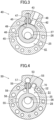
- the first cylinder (40) is configured as a flat, substantially annular member. As illustrated in FIG. 3 , the first cylinder (40) includes a first cylinder chamber (41), a first suction passage (42), and a first blade chamber (43).
- the first cylinder chamber (41) is provided in a center portion of the first cylinder (40).
- the first suction passage (42) extends from the inner wall surface of the first cylinder chamber (41) toward the outside in the radial direction of the first cylinder (40).
- the first suction passage (42) opens on the outer surface of the first cylinder (40).
- the first suction pipe (15) is connected to an inlet end of the first suction passage (42).
- An outlet end of the first suction passage (42) communicates with the first cylinder chamber (41).
- the first cylinder chamber (41) houses a first piston (45).
- the first piston (45) includes a first piston body (46) and a first blade (47).
- the first piston body (46) is formed in an annular shape.
- the first eccentric portion (27) of the drive shaft (25) fits into the first piston body (46).
- the first blade (47) extends radially outward from the first piston body (46).
- the first blade (47) is supported by a pair of first bushes (48).
- the first blade (47) divides the inside of the first cylinder chamber (41) into a low-pressure chamber and a high-pressure chamber.
- the first piston (45) rotates eccentrically in the first cylinder chamber (41) when the drive shaft (25) is driven to rotate.
- the volume of the low-pressure chamber gradually increases with the eccentric rotation of the first piston (45)
- the refrigerant flowing through the first suction pipe (15) is sucked through the first suction passage (42) into the low-pressure chamber in the radial direction.
- the isolated space constitutes a high-pressure chamber.
- the internal pressure of the high-pressure chamber increases as the volume of the high-pressure chamber gradually decreases.
- the refrigerant in the high-pressure chamber flows out of the compression mechanism (30) through the first discharge passage (49).
- the high-pressure refrigerant flows upward through the internal space of the casing (11) and passes through a core cut (not shown) of the motor (21) or any other passage.
- the high-pressure refrigerant that has flowed upward of the motor (21) is transferred to the refrigerant circuit through the discharge pipe (17).
- the first blade chamber (43) is located radially outward of the first cylinder chamber (41) and away from the first cylinder chamber (41).
- the first blade chamber (43) penetrates into the first cylinder (40) in the thickness direction of the first cylinder (40).
- a tip portion of the first blade (47) is housed in the first blade chamber (43).
- the first blade (47) swings in the first blade chamber (43) with the eccentric rotation of the first piston body (46).
- the middle plate (32) is sandwiched between the first cylinder (40) and the second cylinder (50).
- the middle plate (32) is disposed to cover the first cylinder chamber (41) of the first cylinder (40) from below.
- the middle plate (32) is disposed to cover a second cylinder chamber (51) of the second cylinder (50) from above.
- the second cylinder (50) is configured as a flat, substantially annular member.
- the second cylinder (50) includes the second cylinder chamber (51), a second suction passage (52), and a second blade chamber (53).
- the second cylinder chamber (51) is provided in the center of the second cylinder (50).
- the second suction passage (52) extends from the inner wall surface of the second cylinder chamber (51) toward the outside in the radial direction of the second cylinder (50).
- the second suction passage (52) opens on a surface of the second cylinder (50) (a lower surface in FIG. 2 ) facing the rear head (33).
- An inlet end of the second suction passage (52) communicates with an in-head suction passage (70) of the rear head (33), which will be described later.
- An outlet end of the second suction passage (52) communicates with the second cylinder chamber (51).
- the second cylinder chamber (51) houses a second piston (55).
- the second piston (55) includes a second piston body (56) and a second blade (57).
- the second piston body (56) is formed in an annular shape.
- the second eccentric portion (28) of the drive shaft (25) fits into the second piston body (56).
- the second blade (57) extends radially outward from the second piston body (56).
- the second blade (57) is supported by a pair of second bushes (58).
- the second blade (57) divides the inside of the second cylinder chamber (51) into a low-pressure chamber and a high-pressure chamber.
- the action of the second piston (55) is substantially the same as the action of the first piston (45), and will not be described below.
- the second blade chamber (53) is located radially outward of the second cylinder chamber (51) and away from the second cylinder chamber (51).
- the second blade chamber (53) penetrates into the second cylinder (50) in the thickness direction of the second cylinder (50).
- a tip portion of the second blade (57) is housed in the second blade chamber (53).
- the second blade (57) swings in the second blade chamber (53) with the eccentric rotation of the second piston body (56).
- the rear head (33) is stacked on the bottom of the second cylinder (50).
- the rear head (33) is disposed to cover the second cylinder chamber (51) of the second cylinder (50) from below.
- the main shaft portion (26) of the drive shaft (25) is inserted in the rear head (33) to pass through the center of the rear head (33).
- the rear head (33) rotatably supports the drive shaft (25).
- the rear head (33) is provided with the in-head suction passage (70).
- the in-head suction passage (70) includes a first passage (71) and a second passage (72).
- the first passage (71) extends outward in the radial direction of the rear head (33).
- the first passage (71) opens on the outer surface of the rear head (33).
- An inlet end of the first passage (71) is connected to the second suction pipe (16).
- the second passage (72) is provided at an outlet end of the first passage (71).
- the second passage (72) extends upward in the axial direction and opens on the top surface of the rear head (33). An outlet end of the second passage (72) communicates with the second cylinder chamber (51) via the second suction passage (52) of the second cylinder (50).
- This configuration can increase the distance between the first suction pipe (15) and the second suction pipe (16) as compared with the case in which the second suction pipe (16) is connected to the second cylinder (50). This can reduce the thicknesses of the first cylinder (40) and the second cylinder (50) to reduce a leakage loss, making it possible to increase the efficiency of the rotary compressor (10).
- the low-temperature refrigerant that has flowed into the in-head suction passage (70) from the second suction pipe (16) is heated when passing through the first passage (71) and the second passage (72), and then flows into the second cylinder chamber (51). This can reduce direct spraying of the low-temperature refrigerant on the second piston (55).
- the refrigerant is sucked into the second cylinder chamber (51) via the second suction pipe (16), the in-head suction passage (70) of the rear head (33), and the second suction passage (52) of the second cylinder (50).
- the rear head (33) has a second discharge passage (59) penetrating the rear head (33) in the axial direction (see FIG. 4 ).
- the internal pressure of the high-pressure chamber in the second cylinder chamber (51) exceeds a predetermined pressure with the rotation of the second piston (55)
- the refrigerant in the high-pressure chamber flows out of the compression mechanism (30) through the second discharge passage (59).
- the bolt (35) is inserted into the through holes (37) from the rear head (33) side and tightened in the threaded hole (36) of the front head (31).
- the bolt (35) causes the second cylinder (50) near the seat surface of the bolt (35) to have a tightening strain ⁇ 3 which is greater than a tightening strain 61 of the first cylinder (40) ( ⁇ 1 ⁇ ⁇ 3).
- the leakage loss in the second cylinder (50), which is near the seat surface of the bolt (35), can be reduced by setting the clearance between the second cylinder (50) and the second piston (55) small in consideration of the influence of the tightening strain and the thermal strain.
- An accumulator (60) is connected to the upstream side of the rotary compressor (10).
- the accumulator (60) temporarily stores the refrigerant that is to be sucked into the rotary compressor (10) and performs gas-liquid separation for a liquid refrigerant and oil contained in a gas refrigerant.
- the accumulator (60) includes a closed container (61), an inlet pipe (62), a first outlet pipe (63), and a second outlet pipe (64).
- the inlet pipe (62) allows the refrigerant to flow into the closed container (61).
- the outlet pipe (63) allows the refrigerant to flow out of the closed container (61).
- the closed container (61) is configured as a vertically long cylindrical member.
- the inlet pipe (62) is connected to the top of the closed container (61).
- a lower end of the inlet pipe (62) opens in the internal space of the closed container (61) near the top of the closed container (61).
- the first outlet pipe (63) and the second outlet pipe (64) are connected to the bottom of the closed container (61).
- Each of the first outlet pipe (63) and the second outlet pipe (64) has an upper end portion extending upward in the internal space of the closed container (61) and opens near the top of the closed container (61).
- the first outlet pipe (63) has a lower end portion that extends downward from the lower end of the closed container (61), bends toward the first suction pipe (15) of the rotary compressor (10), and is connected to the first suction pipe (15).
- the second outlet pipe (64) has a lower end portion that extends downward from the lower end of the closed container (61), bends toward the second suction pipe (16) of the rotary compressor (10), and is connected to the second suction pipe (16).
- the distance between the first suction pipe (15) and the second suction pipe (16) can be increased as compared with the case in which the second suction pipe (16) is connected to the second cylinder (50). This can reduce the thicknesses of the first cylinder (40) and the second cylinder (50) to reduce the leakage loss, making it possible to increase the efficiency of the rotary compressor.
- connecting the first suction pipe (15) to the first cylinder (40) can reduce suction and heating of the refrigerant in the first cylinder chamber (41). This can improve the efficiency of the rotary compressor (10) as compared with the case in which the first suction pipe (15) is connected to the first head (31) and the second suction pipe (16) is connected to the second head (33).
- the bolt (35) when tightened, causes the second cylinder (50) near the seat surface of the bolt (35) to have a tightening strain greater than a tightening strain of the first cylinder (40).
- the fluid when the fluid is sucked into the second cylinder (50) from the second head (33) side, the low-temperature fluid is heated while passing through the in-head suction passage (70), which reduces the difference in temperature distribution between the second cylinder (50) and the fluid. This causes a thermal strain of the second cylinder (50) due to thermal expansion to be lower than a thermal strain of the first cylinder (40).
- the leakage loss in the second cylinder (50), which is near the seat surface of the bolt (35), can be reduced by setting the clearance between the second cylinder (50) and the second piston (55) small in consideration of the influence of the tightening strain and the thermal strain.
- connecting the first suction pipe (15) to the first cylinder (40) located near the first head (31) provided with the threaded hole (36) can reduce a suction pressure loss of the refrigerant. This can reduce the loss of the compression mechanism (30) as a whole, making it possible to improve the efficiency of the rotary compressor (10).
- the low-temperature fluid that has flowed into the in-head suction passage (70) from the second suction pipe (16) is heated when passing through the first passage (71) and the second passage (72), and then flows into the second cylinder chamber (51) in the radial direction. This can reduce direct spraying of the low-temperature fluid on the second piston (55).
- the refrigeration apparatus includes the rotary compressor (10) and the fluid circuit (1a) through which the fluid compressed by the rotary compressor (10) flows.
- This can provide a refrigeration apparatus including the rotary compressor (10).
- a compression mechanism (30) is disposed below the motor (21).
- the compression mechanism (30) includes a front head (31), a first cylinder (40), a middle plate (32), a second cylinder (50), and a rear head (33).
- the front head (31), the first cylinder (40), the middle plate (32), the second cylinder (50), and the rear head (33) are stacked in this order from top to bottom and fixed with bolts (35).
- the first cylinder (40) has a threaded hole (36).
- the front head (31), the middle plate (32), the second cylinder (50), and the rear head (33) are each provided with a through hole (37) located to correspond to the threaded hole (36).
- the front head (31) has a counterbore located to correspond to the through hole (37).
- the lower one of the bolts (35) is inserted into the holes from the rear head (33) side and fastens the first cylinder (40), the middle plate (32), the second cylinder (50), and the rear head (33).
- the upper one of the bolts (35) is inserted into the holes from the front head (31) side and fastens the front head (31) and the first cylinder (40).
- the leakage loss in the second cylinder (50), which is near the seat surface of the bolt (35), can be reduced by setting the clearance between the second cylinder (50) and the second piston (55) small in consideration of the influence of the tightening strain and the thermal strain.
- the present disclosure is useful for a rotary compressor and a refrigeration apparatus.
Landscapes
- Engineering & Computer Science (AREA)
- Mechanical Engineering (AREA)
- General Engineering & Computer Science (AREA)
- Physics & Mathematics (AREA)
- Thermal Sciences (AREA)
- Applications Or Details Of Rotary Compressors (AREA)
- Rotary Pumps (AREA)
Abstract
Description
- The present disclosure relates to a rotary compressor and a refrigeration apparatus.
- Patent Document 1 discloses a compressor including a front head, a first cylinder having a first cylinder chamber, a partition plate, a second cylinder having a second cylinder chamber, and a rear head. A first suction pipe is connected to the first cylinder, and a second suction pipe is connected to the second cylinder. Refrigerant gas is sucked into the first cylinder chamber and the second cylinder chamber from an accumulator via the first suction pipe and the second suction pipe.
- Patent Document 1:
Japanese Unexamined Patent Publication No. 2022-072807 - For the higher efficiency of the compressor, reducing a leakage loss by thinning the first and second cylinders has been demanded.
- However, thinning the first and second cylinders reduces the distance between the first and second suction pipes, which may decrease the strength of the casing around connections with the first and second suction pipes.
- An object of the present disclosure is to increase the efficiency of the compressor and increase the distance between the first suction pipe and the second suction pipe.
- A first aspect of the present disclosure is directed to a rotary compressor including: a rotary compressor including: a stack of a first head (31), a first cylinder (40) having a first cylinder chamber (41), a middle plate (32), a second cylinder (50) having a second cylinder chamber (51), and a second head (33); a first piston (45) that eccentrically rotates in the first cylinder chamber (41); and a second piston (55) that eccentrically rotates in the second cylinder chamber (51), the rotary compressor including: a first suction pipe (15) that is connected to the first cylinder (40) and sucks a fluid into the first cylinder chamber (41); an in-head suction passage (70) that is provided in the second head (33) and communicates with the second cylinder chamber (51); and a second suction pipe (16) that is connected to the second head (33) and sucks a fluid into the second cylinder chamber (51) through the in-head suction passage (70).
- According to the first aspect, the distance between the first suction pipe (15) and the second suction pipe (16) can be increased as compared with the case in which the second suction pipe (16) is connected to the second cylinder (50). This can reduce the thicknesses of the first cylinder (40) and the second cylinder (50) to reduce the leakage loss, making it possible to increase the efficiency of the rotary compressor.
- A second aspect of the present disclosure is an embodiment of the first aspect. In the rotary compressor of the second aspect, the first head (31) has a threaded hole (36), the first cylinder (40), the middle plate (32), the second cylinder (50), and the second head (33) each have a through hole (37) located to correspond to the threaded hole (36), and a bolt (35) is inserted from the second head (33) side to fasten the first head (31), the first cylinder (40), the middle plate (32), the second cylinder (50), and the second head (33).
- According to the second aspect, when tightened, the bolt (35) causes the second cylinder (50) near the seat surface of the bolt (35) to have a tightening strain greater than a tightening strain of the first cylinder (40). On the other hand, when the fluid is sucked into the second cylinder (50) from the second head (33) side, the low-temperature fluid is heated while passing through the in-head suction passage (70), which reduces the difference in temperature distribution between the second cylinder (50) and the fluid. This causes a thermal strain of the second cylinder (50) due to thermal expansion to be lower than a thermal strain of the first cylinder (40).
- Thus, the leakage loss in the second cylinder (50), which is near the seat surface of the bolt (35), can be reduced by setting the clearance between the second cylinder (50) and the second piston (55) small in consideration of the influence of the tightening strain and the thermal strain.
- A third aspect of the present disclosure is an embodiment of the first aspect. In the rotary compressor of the third aspect, the first cylinder (40) has a threaded hole (36), the middle plate (32), the second cylinder (50), and the second head (33) each have a through hole (37) located to correspond to the threaded hole (36), and a bolt (35) is inserted from the second head (33) side to fasten the first cylinder (40), the middle plate (32), the second cylinder (50), and the second head (33).
- According to the third aspect, the leakage loss in the second cylinder (50), which is near the seat surface of the bolt (35), can be reduced by setting the clearance between the second cylinder (50) and the second piston (55) small in consideration of the influence of the tightening strain and the thermal strain.
- A fourth aspect of the present disclosure is an embodiment of any one of the first to third aspects. In the rotary compressor of the fourth aspect, the in-head suction passage (70) includes: a first passage (71) extending in a radial direction; and a second passage (72) extending in an axial direction to allow the first passage (71) and the second cylinder chamber (51) to communicate with each other.
- According to the fourth aspect, the low-temperature fluid that has flowed into the in-head suction passage (70) from the second suction pipe (16) is heated when passing through the first passage (71) and the second passage (72), and then flows into the second cylinder chamber (51) in the radial direction. This can reduce direct spraying of the low-temperature fluid on the second piston (55).
- A fifth aspect of the present disclosure is directed to a refrigeration apparatus including: the rotary compressor (10) of any one of the first to fourth aspects; and a fluid circuit (1a) through which a fluid compressed by the rotary compressor (10) flows.
- According to the fifth aspect, a refrigeration apparatus including the rotary compressor (10) can be provided.
-
-
FIG. 1 is a refrigerant circuit diagram illustrating a configuration of a refrigeration apparatus according to a first embodiment. -
FIG. 2 is a longitudinal sectional view illustrating a configuration of a rotary compressor. -
FIG. 3 is a transverse sectional view illustrating a configuration of a first cylinder and a first piston. -
FIG. 4 is a transverse sectional view illustrating a configuration of a second cylinder and a second piston. -
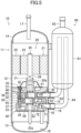
FIG. 5 is a longitudinal sectional view illustrating a configuration of a rotary compressor according to a second embodiment. - As illustrated in
FIG. 1 , a rotary compressor (10) is provided in a refrigeration apparatus (1). The refrigeration apparatus (1) includes a refrigerant circuit (1a) which is a fluid circuit filled with a refrigerant. The refrigerant circuit (1a) includes a rotary compressor (10), a radiator (3), a decompression mechanism (4), and an evaporator (5). The decompression mechanism (4) is, for example, an expansion valve. The refrigerant circuit (1a) performs a vapor compression refrigeration cycle. - The refrigeration apparatus (1) is an air conditioner. The air conditioner may be any of a cooling-only apparatus, a heating-only apparatus, or an air conditioner switchable between cooling and heating. In this case, the air conditioner has a switching mechanism (e.g., a four-way switching valve) configured to switch the direction of circulation of the refrigerant. The refrigeration apparatus (1) may be a water heater, a chiller unit, or a cooling apparatus configured to cool air in an internal space. The cooling apparatus cools the air in a refrigerator, a freezer, or a container, for example.
- As illustrated in
FIG. 2 , the rotary compressor (10) includes a casing (11), a drive mechanism (20), and a compression mechanism (30). The drive mechanism (20) and the compression mechanism (30) are housed in the casing (11). - The casing (11) is configured as a vertically long cylindrical closed container. The casing (11) includes a barrel (12), a bottom end plate (13), and a top end plate (14). The barrel (12) is in the shape of a cylinder extending in the vertical direction, with both axial ends open. The bottom end plate (13) is fixed to the lower end of the barrel (12). The top end plate (14) is fixed to the upper end of the barrel (12).
- A first suction pipe (15) and a second suction pipe (16) pass through, and are fixed to, the barrel (12). A discharge pipe (17) passes through, and is fixed to, the top end plate (14).
- The casing (11) has an oil reservoir (18) at its bottom. The oil reservoir (18) is formed by the bottom end plate (13) and an inner wall of a lower portion of the barrel (12). The oil reservoir (18) stores oil for lubricating the sliding portions of the compression mechanism (30) and a drive shaft (25).
- The drive mechanism (20) includes a motor (21) and a drive shaft (25). The motor (21) is disposed above the compression mechanism (30). The motor (21) includes a stator (22) and a rotor (23).
- The stator (22) is fixed to the inner peripheral surface of the barrel (12) of the casing (11). The rotor (23) extends to penetrate the stator (22) in the vertical direction. The drive shaft (25) passes through the axis of the rotor (23) and is fixed to the rotor (23). The drive shaft (25) is driven to rotate together with the rotor (23) when the motor (21) is energized.
- The drive shaft (25) is arranged on the axis of the barrel (12) of the casing (11). An oil supply pump (25a) is provided at the lower end of the drive shaft (25). The oil supply pump (25a) conveys the oil collected in the oil reservoir (18). The conveyed oil is supplied to the sliding portions of the compression mechanism (30) and the drive shaft (25) through an oil passage (25b) in the drive shaft (25).
- The drive shaft (25) includes a main shaft portion (26), a first eccentric portion (27), and a second eccentric portion (28). An upper part of the main shaft portion (26) is fixed to the rotor (23) of the motor (21). The first eccentric portion (27) is disposed above the second eccentric portion (28). The axes of the first eccentric portion (27) and the second eccentric portion (28) are eccentric from the axis of the main shaft portion (26) by a predetermined amount.
- Part of the main shaft portion (26) above the first eccentric portion (27) is rotatably supported by a front head (31) described later. Part of the main shaft portion (26) below the second eccentric portion (28) is rotatably supported by a rear head (33) described later.
- In the example shown in
FIG. 2 , the compression mechanism (30) is a two-cylinder rotary fluid machine. The compression mechanism (30) is disposed below the motor (21). The compression mechanism (30) includes a front head (31) as a first head, a first cylinder (40), a middle plate (32), a second cylinder (50), and a rear head (33) as a second head. - The front head (31), the first cylinder (40), the middle plate (32), the second cylinder (50), and the rear head (33) are stacked in this order from top to bottom and fixed with a bolt (35).
- Specifically, the front head (31) is provided with a threaded hole (36). The first cylinder (40), the middle plate (32), the second cylinder (50), and the rear head (33) are each provided with a through hole (37) located to correspond to the threaded hole (36).
- The bolt (35) is inserted into the holes from the rear head (33) side and fastens the front head (31), the first cylinder (40), the middle plate (32), the second cylinder (50), and the rear head (33).
- The front head (31) is fixed to the barrel (12) of the casing (11). The front head (31) is stacked on top of the first cylinder (40). The front head (31) is arranged to cover a first cylinder chamber (41) of the first cylinder (40) from above. The main shaft portion (26) of the drive shaft (25) is inserted in the front head (31) to pass through the center of the front head (31). The front head (31) rotatably supports the drive shaft (25). The front head (31) has a first discharge passage (49) penetrating the front head (31) in the axial direction (see
FIG. 3 ). - The first cylinder (40) is configured as a flat, substantially annular member. As illustrated in
FIG. 3 , the first cylinder (40) includes a first cylinder chamber (41), a first suction passage (42), and a first blade chamber (43). - The first cylinder chamber (41) is provided in a center portion of the first cylinder (40). The first suction passage (42) extends from the inner wall surface of the first cylinder chamber (41) toward the outside in the radial direction of the first cylinder (40). The first suction passage (42) opens on the outer surface of the first cylinder (40). The first suction pipe (15) is connected to an inlet end of the first suction passage (42). An outlet end of the first suction passage (42) communicates with the first cylinder chamber (41).
- The first cylinder chamber (41) houses a first piston (45). The first piston (45) includes a first piston body (46) and a first blade (47). The first piston body (46) is formed in an annular shape. The first eccentric portion (27) of the drive shaft (25) fits into the first piston body (46). The first blade (47) extends radially outward from the first piston body (46). The first blade (47) is supported by a pair of first bushes (48). The first blade (47) divides the inside of the first cylinder chamber (41) into a low-pressure chamber and a high-pressure chamber.
- The first piston (45) rotates eccentrically in the first cylinder chamber (41) when the drive shaft (25) is driven to rotate. When the volume of the low-pressure chamber gradually increases with the eccentric rotation of the first piston (45), the refrigerant flowing through the first suction pipe (15) is sucked through the first suction passage (42) into the low-pressure chamber in the radial direction.
- When the low-pressure chamber is isolated from the first suction passage (42), the isolated space constitutes a high-pressure chamber. The internal pressure of the high-pressure chamber increases as the volume of the high-pressure chamber gradually decreases. When the internal pressure of the high-pressure chamber exceeds a predetermined pressure, the refrigerant in the high-pressure chamber flows out of the compression mechanism (30) through the first discharge passage (49). The high-pressure refrigerant flows upward through the internal space of the casing (11) and passes through a core cut (not shown) of the motor (21) or any other passage. The high-pressure refrigerant that has flowed upward of the motor (21) is transferred to the refrigerant circuit through the discharge pipe (17).
- The first blade chamber (43) is located radially outward of the first cylinder chamber (41) and away from the first cylinder chamber (41). The first blade chamber (43) penetrates into the first cylinder (40) in the thickness direction of the first cylinder (40). A tip portion of the first blade (47) is housed in the first blade chamber (43). The first blade (47) swings in the first blade chamber (43) with the eccentric rotation of the first piston body (46).
- As illustrated in
FIG. 2 , the middle plate (32) is sandwiched between the first cylinder (40) and the second cylinder (50). The middle plate (32) is disposed to cover the first cylinder chamber (41) of the first cylinder (40) from below. The middle plate (32) is disposed to cover a second cylinder chamber (51) of the second cylinder (50) from above. - As also illustrated in
FIG. 4 , the second cylinder (50) is configured as a flat, substantially annular member. The second cylinder (50) includes the second cylinder chamber (51), a second suction passage (52), and a second blade chamber (53). - The second cylinder chamber (51) is provided in the center of the second cylinder (50). The second suction passage (52) extends from the inner wall surface of the second cylinder chamber (51) toward the outside in the radial direction of the second cylinder (50). The second suction passage (52) opens on a surface of the second cylinder (50) (a lower surface in
FIG. 2 ) facing the rear head (33). - An inlet end of the second suction passage (52) communicates with an in-head suction passage (70) of the rear head (33), which will be described later. An outlet end of the second suction passage (52) communicates with the second cylinder chamber (51).
- The second cylinder chamber (51) houses a second piston (55). The second piston (55) includes a second piston body (56) and a second blade (57). The second piston body (56) is formed in an annular shape. The second eccentric portion (28) of the drive shaft (25) fits into the second piston body (56). The second blade (57) extends radially outward from the second piston body (56). The second blade (57) is supported by a pair of second bushes (58). The second blade (57) divides the inside of the second cylinder chamber (51) into a low-pressure chamber and a high-pressure chamber.
- The action of the second piston (55) is substantially the same as the action of the first piston (45), and will not be described below.
- The second blade chamber (53) is located radially outward of the second cylinder chamber (51) and away from the second cylinder chamber (51). The second blade chamber (53) penetrates into the second cylinder (50) in the thickness direction of the second cylinder (50). A tip portion of the second blade (57) is housed in the second blade chamber (53). The second blade (57) swings in the second blade chamber (53) with the eccentric rotation of the second piston body (56).
- As illustrated in
FIG. 2 , the rear head (33) is stacked on the bottom of the second cylinder (50). The rear head (33) is disposed to cover the second cylinder chamber (51) of the second cylinder (50) from below. The main shaft portion (26) of the drive shaft (25) is inserted in the rear head (33) to pass through the center of the rear head (33). The rear head (33) rotatably supports the drive shaft (25). - The rear head (33) is provided with the in-head suction passage (70). The in-head suction passage (70) includes a first passage (71) and a second passage (72). The first passage (71) extends outward in the radial direction of the rear head (33). The first passage (71) opens on the outer surface of the rear head (33). An inlet end of the first passage (71) is connected to the second suction pipe (16). The second passage (72) is provided at an outlet end of the first passage (71).
- The second passage (72) extends upward in the axial direction and opens on the top surface of the rear head (33). An outlet end of the second passage (72) communicates with the second cylinder chamber (51) via the second suction passage (52) of the second cylinder (50).
- This configuration can increase the distance between the first suction pipe (15) and the second suction pipe (16) as compared with the case in which the second suction pipe (16) is connected to the second cylinder (50). This can reduce the thicknesses of the first cylinder (40) and the second cylinder (50) to reduce a leakage loss, making it possible to increase the efficiency of the rotary compressor (10).
- The low-temperature refrigerant that has flowed into the in-head suction passage (70) from the second suction pipe (16) is heated when passing through the first passage (71) and the second passage (72), and then flows into the second cylinder chamber (51). This can reduce direct spraying of the low-temperature refrigerant on the second piston (55).
- As indicated by the arrows in
FIG. 2 , the refrigerant is sucked into the second cylinder chamber (51) via the second suction pipe (16), the in-head suction passage (70) of the rear head (33), and the second suction passage (52) of the second cylinder (50). - The rear head (33) has a second discharge passage (59) penetrating the rear head (33) in the axial direction (see
FIG. 4 ). When the internal pressure of the high-pressure chamber in the second cylinder chamber (51) exceeds a predetermined pressure with the rotation of the second piston (55), the refrigerant in the high-pressure chamber flows out of the compression mechanism (30) through the second discharge passage (59). - The bolt (35) is inserted into the through holes (37) from the rear head (33) side and tightened in the threaded hole (36) of the front head (31). When tightened, the bolt (35) causes the second cylinder (50) near the seat surface of the bolt (35) to have a tightening strain δ3 which is greater than a tightening
strain 61 of the first cylinder (40) (δ1 < δ3). - On the other hand, when the fluid is sucked into the second cylinder (50) from the second head (33) side, the low-temperature fluid is heated while passing through the in-head suction passage (70), which reduces the difference in temperature distribution between the second cylinder (50) and the fluid. This causes a thermal strain δ4 of the second cylinder (50) due to thermal expansion to be lower than a thermal strain δ2 of the first cylinder (40) (δ2 > δ4).
- Thus, the leakage loss in the second cylinder (50), which is near the seat surface of the bolt (35), can be reduced by setting the clearance between the second cylinder (50) and the second piston (55) small in consideration of the influence of the tightening strain and the thermal strain.
- An accumulator (60) is connected to the upstream side of the rotary compressor (10). The accumulator (60) temporarily stores the refrigerant that is to be sucked into the rotary compressor (10) and performs gas-liquid separation for a liquid refrigerant and oil contained in a gas refrigerant.
- The accumulator (60) includes a closed container (61), an inlet pipe (62), a first outlet pipe (63), and a second outlet pipe (64). The inlet pipe (62) allows the refrigerant to flow into the closed container (61). The outlet pipe (63) allows the refrigerant to flow out of the closed container (61).
- The closed container (61) is configured as a vertically long cylindrical member. The inlet pipe (62) is connected to the top of the closed container (61). A lower end of the inlet pipe (62) opens in the internal space of the closed container (61) near the top of the closed container (61).
- The first outlet pipe (63) and the second outlet pipe (64) are connected to the bottom of the closed container (61). Each of the first outlet pipe (63) and the second outlet pipe (64) has an upper end portion extending upward in the internal space of the closed container (61) and opens near the top of the closed container (61).
- The first outlet pipe (63) has a lower end portion that extends downward from the lower end of the closed container (61), bends toward the first suction pipe (15) of the rotary compressor (10), and is connected to the first suction pipe (15). The second outlet pipe (64) has a lower end portion that extends downward from the lower end of the closed container (61), bends toward the second suction pipe (16) of the rotary compressor (10), and is connected to the second suction pipe (16).
- According to the features of this embodiment, the distance between the first suction pipe (15) and the second suction pipe (16) can be increased as compared with the case in which the second suction pipe (16) is connected to the second cylinder (50). This can reduce the thicknesses of the first cylinder (40) and the second cylinder (50) to reduce the leakage loss, making it possible to increase the efficiency of the rotary compressor.
- Further, connecting the first suction pipe (15) to the first cylinder (40) can reduce suction and heating of the refrigerant in the first cylinder chamber (41). This can improve the efficiency of the rotary compressor (10) as compared with the case in which the first suction pipe (15) is connected to the first head (31) and the second suction pipe (16) is connected to the second head (33).
- According to the features of this embodiment, when tightened, the bolt (35) causes the second cylinder (50) near the seat surface of the bolt (35) to have a tightening strain greater than a tightening strain of the first cylinder (40). On the other hand, when the fluid is sucked into the second cylinder (50) from the second head (33) side, the low-temperature fluid is heated while passing through the in-head suction passage (70), which reduces the difference in temperature distribution between the second cylinder (50) and the fluid. This causes a thermal strain of the second cylinder (50) due to thermal expansion to be lower than a thermal strain of the first cylinder (40).
- Thus, the leakage loss in the second cylinder (50), which is near the seat surface of the bolt (35), can be reduced by setting the clearance between the second cylinder (50) and the second piston (55) small in consideration of the influence of the tightening strain and the thermal strain.
- Further, connecting the first suction pipe (15) to the first cylinder (40) located near the first head (31) provided with the threaded hole (36) can reduce a suction pressure loss of the refrigerant. This can reduce the loss of the compression mechanism (30) as a whole, making it possible to improve the efficiency of the rotary compressor (10).
- According to the features of this embodiment, the low-temperature fluid that has flowed into the in-head suction passage (70) from the second suction pipe (16) is heated when passing through the first passage (71) and the second passage (72), and then flows into the second cylinder chamber (51) in the radial direction. This can reduce direct spraying of the low-temperature fluid on the second piston (55).
- According to the features of this embodiment, the refrigeration apparatus includes the rotary compressor (10) and the fluid circuit (1a) through which the fluid compressed by the rotary compressor (10) flows. This can provide a refrigeration apparatus including the rotary compressor (10).
- In the following description, the same reference characters designate the same components as those of the first embodiment, and the description is focused only on the difference.
- As illustrated in
FIG. 5 , a compression mechanism (30) is disposed below the motor (21). The compression mechanism (30) includes a front head (31), a first cylinder (40), a middle plate (32), a second cylinder (50), and a rear head (33). - The front head (31), the first cylinder (40), the middle plate (32), the second cylinder (50), and the rear head (33) are stacked in this order from top to bottom and fixed with bolts (35).
- Specifically, the first cylinder (40) has a threaded hole (36). The front head (31), the middle plate (32), the second cylinder (50), and the rear head (33) are each provided with a through hole (37) located to correspond to the threaded hole (36). The front head (31) has a counterbore located to correspond to the through hole (37).
- The lower one of the bolts (35) is inserted into the holes from the rear head (33) side and fastens the first cylinder (40), the middle plate (32), the second cylinder (50), and the rear head (33). The upper one of the bolts (35) is inserted into the holes from the front head (31) side and fastens the front head (31) and the first cylinder (40).
- According to the features of this embodiment, the leakage loss in the second cylinder (50), which is near the seat surface of the bolt (35), can be reduced by setting the clearance between the second cylinder (50) and the second piston (55) small in consideration of the influence of the tightening strain and the thermal strain.
- While the embodiments and variations have been described above, it will be understood that various changes in form and details can be made without departing from the spirit and scope of the claims. The elements according to embodiments, the variations thereof, and the other embodiments may be combined and replaced with each other. In addition, the expressions of "first," "second," "third," ... , in the specification and claims are used to distinguish the terms to which these expressions are given, and do not limit the number and order of the terms.
- As can be seen from the foregoing description, the present disclosure is useful for a rotary compressor and a refrigeration apparatus.
-
- 1
- Refrigeration Apparatus
- 1a
- Fluid Circuit
- 10
- Rotary Compressor
- 15
- First Suction Pipe
- 16
- Second Suction Pipe
- 31
- Front Head (First Head)
- 32
- Middle Plate
- 33
- Rear Head (Second Head)
- 35
- Bolt
- 36
- Threaded Hole
- 37
- Through Hole
- 40
- First Cylinder
- 41
- First Cylinder Chamber
- 45
- First Piston
- 50
- Second Cylinder
- 51
- Second Cylinder Chamber
- 55
- Second Piston
- 70
- In-Head Suction Passage
- 71
- First Passage
- 72
- Second Passage
Claims (5)
- A rotary compressor including: a stack of a first head (31), a first cylinder (40) having a first cylinder chamber (41), a middle plate (32), a second cylinder (50) having a second cylinder chamber (51), and a second head (33); a first piston (45) that eccentrically rotates in the first cylinder chamber (41); and a second piston (55) that eccentrically rotates in the second cylinder chamber (51), the rotary compressor comprising:a first suction pipe (15) that is connected to the first cylinder (40) and sucks a fluid into the first cylinder chamber (41);an in-head suction passage (70) that is provided in the second head (33) and communicates with the second cylinder chamber (51); anda second suction pipe (16) that is connected to the second head (33) and sucks a fluid into the second cylinder chamber (51) through the in-head suction passage (70).
- The rotary compressor of claim 1, whereinthe first head (31) has a threaded hole (36),the first cylinder (40), the middle plate (32), the second cylinder (50), and the second head (33) each have a through hole (37) located to correspond to the threaded hole (36), anda bolt (35) is inserted from the second head (33) side to fasten the first head (31), the first cylinder (40), the middle plate (32), the second cylinder (50), and the second head (33).
- The rotary compressor of claim 1, whereinthe first cylinder (40) has a threaded hole (36),the middle plate (32), the second cylinder (50), and the second head (33) each have a through hole (37) located to correspond to the threaded hole (36), anda bolt (35) is inserted from the second head (33) side to fasten the first cylinder (40), the middle plate (32), the second cylinder (50), and the second head (33).
- The rotary compressor of any one of claims 1 to 3, wherein
the in-head suction passage (70) includes: a first passage (71) extending in a radial direction; and a second passage (72) extending in an axial direction to allow the first passage (71) and the second cylinder chamber (51) to communicate with each other. - A refrigeration apparatus, comprising: the rotary compressor (10) of any one of claims 1 to 4; and
a fluid circuit (1a) through which a fluid compressed by the rotary compressor (10) flows.
Applications Claiming Priority (2)
| Application Number | Priority Date | Filing Date | Title |
|---|---|---|---|
| JP2023053770A JP7761846B2 (en) | 2023-03-29 | 2023-03-29 | Rotary compressor and refrigeration device |
| PCT/JP2024/008357 WO2024203041A1 (en) | 2023-03-29 | 2024-03-05 | Rotary compressor and refrigeration device |
Publications (2)
| Publication Number | Publication Date |
|---|---|
| EP4461962A1 true EP4461962A1 (en) | 2024-11-13 |
| EP4461962A4 EP4461962A4 (en) | 2025-04-09 |
Family
ID=91670392
Family Applications (1)
| Application Number | Title | Priority Date | Filing Date |
|---|---|---|---|
| EP24732156.5A Pending EP4461962A4 (en) | 2023-03-29 | 2024-03-05 | Rotary compressor and refrigeration device |
Country Status (5)
| Country | Link |
|---|---|
| US (1) | US20250320870A1 (en) |
| EP (1) | EP4461962A4 (en) |
| JP (1) | JP7761846B2 (en) |
| CN (1) | CN120530265A (en) |
| WO (1) | WO2024203041A1 (en) |
Family Cites Families (6)
| Publication number | Priority date | Publication date | Assignee | Title |
|---|---|---|---|---|
| TWI308631B (en) * | 2002-11-07 | 2009-04-11 | Sanyo Electric Co | Multistage compression type rotary compressor and cooling device |
| JP2004156539A (en) * | 2002-11-07 | 2004-06-03 | Sanyo Electric Co Ltd | Multiple stage compression rotary compressor |
| JP4396773B2 (en) * | 2008-02-04 | 2010-01-13 | ダイキン工業株式会社 | Fluid machinery |
| JP5217856B2 (en) * | 2008-09-30 | 2013-06-19 | ダイキン工業株式会社 | Rotary compressor |
| JP7013327B2 (en) * | 2018-05-31 | 2022-01-31 | 株式会社東芝 | Crankshaft, crankshaft assembly method, rotary compressor and refrigeration cycle equipment |
| JP2022072807A (en) | 2020-10-30 | 2022-05-17 | ダイキン工業株式会社 | Compressor, method of manufacturing compressor, and air conditioner |
-
2023
- 2023-03-29 JP JP2023053770A patent/JP7761846B2/en active Active
-
2024
- 2024-03-05 EP EP24732156.5A patent/EP4461962A4/en active Pending
- 2024-03-05 WO PCT/JP2024/008357 patent/WO2024203041A1/en not_active Ceased
- 2024-03-05 CN CN202480008059.7A patent/CN120530265A/en active Pending
-
2025
- 2025-06-27 US US19/253,399 patent/US20250320870A1/en active Pending
Also Published As
| Publication number | Publication date |
|---|---|
| JP7761846B2 (en) | 2025-10-29 |
| US20250320870A1 (en) | 2025-10-16 |
| WO2024203041A1 (en) | 2024-10-03 |
| JP2024141900A (en) | 2024-10-10 |
| EP4461962A4 (en) | 2025-04-09 |
| CN120530265A (en) | 2025-08-22 |
Similar Documents
| Publication | Publication Date | Title |
|---|---|---|
| US8985985B2 (en) | Rotary compressor and refrigeration cycle apparatus | |
| US8985984B2 (en) | Rotary compressor and refrigeration cycle apparatus | |
| KR100757179B1 (en) | Fluid machinery | |
| EP2357427A1 (en) | Refrigeration device | |
| US20100326124A1 (en) | Expander-integrated compressor and refrigeration cycle apparatus using the same | |
| EP2090746B1 (en) | Freezing apparatus, and expander | |
| CN112771323A (en) | Multi-stage compression system | |
| CN112771322A (en) | Multi-stage compression system | |
| CN112752934A (en) | Multi-stage compression system | |
| EP1795701A1 (en) | Fluid machine | |
| CN112771324A (en) | Multi-stage compression system | |
| US9951774B2 (en) | Lubrication of a rotary compressor | |
| JP2005146986A (en) | Heat exchanger integral type compressor with built-in accumulator | |
| US20250320870A1 (en) | Rotary compressor and refrigeration apparatus | |
| US20150300337A1 (en) | Compressor | |
| EP4534842A1 (en) | Compressor and refrigeration cycle device | |
| EP3636929B1 (en) | Rotary compressor | |
| WO2007119307A1 (en) | Fluid machine | |
| EP4459128A1 (en) | Rotary compressor and refrigeration apparatus | |
| JP6841272B2 (en) | Rotary compressor | |
| JP7727230B1 (en) | Rotary compressor and refrigeration device | |
| EP4729784A1 (en) | Rotary compressor and refrigeration apparatus | |
| JP2026060594A (en) | Rotary compressor and refrigeration system | |
| EP4707601A1 (en) | Rotary compressor and refrigeration device | |
| JP2023162552A (en) | Rotary compressor and refrigeration equipment |
Legal Events
| Date | Code | Title | Description |
|---|---|---|---|
| STAA | Information on the status of an ep patent application or granted ep patent |
Free format text: STATUS: UNKNOWN |
|
| STAA | Information on the status of an ep patent application or granted ep patent |
Free format text: STATUS: THE INTERNATIONAL PUBLICATION HAS BEEN MADE |
|
| PUAI | Public reference made under article 153(3) epc to a published international application that has entered the european phase |
Free format text: ORIGINAL CODE: 0009012 |
|
| STAA | Information on the status of an ep patent application or granted ep patent |
Free format text: STATUS: REQUEST FOR EXAMINATION WAS MADE |
|
| 17P | Request for examination filed |
Effective date: 20240619 |
|
| AK | Designated contracting states |
Kind code of ref document: A1 Designated state(s): AL AT BE BG CH CY CZ DE DK EE ES FI FR GB GR HR HU IE IS IT LI LT LU LV MC ME MK MT NL NO PL PT RO RS SE SI SK SM TR |
|
| P01 | Opt-out of the competence of the unified patent court (upc) registered |
Free format text: CASE NUMBER: APP_991/2025 Effective date: 20250108 |
|
| A4 | Supplementary search report drawn up and despatched |
Effective date: 20250310 |
|
| RIC1 | Information provided on ipc code assigned before grant |
Ipc: F04C 2/344 20060101ALI20250304BHEP Ipc: F04C 29/12 20060101AFI20250304BHEP |
|
| STAA | Information on the status of an ep patent application or granted ep patent |
Free format text: STATUS: EXAMINATION IS IN PROGRESS |
|
| 17Q | First examination report despatched |
Effective date: 20251111 |