EP4461937A1 - Torsional damper - Google Patents
Torsional damper Download PDFInfo
- Publication number
- EP4461937A1 EP4461937A1 EP22918811.5A EP22918811A EP4461937A1 EP 4461937 A1 EP4461937 A1 EP 4461937A1 EP 22918811 A EP22918811 A EP 22918811A EP 4461937 A1 EP4461937 A1 EP 4461937A1
- Authority
- EP
- European Patent Office
- Prior art keywords
- stays
- hub
- axial
- torsional damper
- wavelength
- Prior art date
- Legal status (The legal status is an assumption and is not a legal conclusion. Google has not performed a legal analysis and makes no representation as to the accuracy of the status listed.)
- Pending
Links
Images




Classifications
-
- F—MECHANICAL ENGINEERING; LIGHTING; HEATING; WEAPONS; BLASTING
- F16—ENGINEERING ELEMENTS AND UNITS; GENERAL MEASURES FOR PRODUCING AND MAINTAINING EFFECTIVE FUNCTIONING OF MACHINES OR INSTALLATIONS; THERMAL INSULATION IN GENERAL
- F16F—SPRINGS; SHOCK-ABSORBERS; MEANS FOR DAMPING VIBRATION
- F16F15/00—Suppression of vibrations in systems; Means or arrangements for avoiding or reducing out-of-balance forces, e.g. due to motion
- F16F15/10—Suppression of vibrations in rotating systems by making use of members moving with the system
- F16F15/12—Suppression of vibrations in rotating systems by making use of members moving with the system using elastic members or friction-damping members, e.g. between a rotating shaft and a gyratory mass mounted thereon
- F16F15/121—Suppression of vibrations in rotating systems by making use of members moving with the system using elastic members or friction-damping members, e.g. between a rotating shaft and a gyratory mass mounted thereon using springs as elastic members, e.g. metallic springs
- F16F15/124—Elastomeric springs
- F16F15/126—Elastomeric springs consisting of at least one annular element surrounding the axis of rotation
-
- F—MECHANICAL ENGINEERING; LIGHTING; HEATING; WEAPONS; BLASTING
- F16—ENGINEERING ELEMENTS AND UNITS; GENERAL MEASURES FOR PRODUCING AND MAINTAINING EFFECTIVE FUNCTIONING OF MACHINES OR INSTALLATIONS; THERMAL INSULATION IN GENERAL
- F16H—GEARING
- F16H55/00—Elements with teeth or friction surfaces for conveying motion; Worms, pulleys or sheaves for gearing mechanisms
- F16H55/32—Friction members
- F16H55/36—Pulleys
-
- F—MECHANICAL ENGINEERING; LIGHTING; HEATING; WEAPONS; BLASTING
- F02—COMBUSTION ENGINES; HOT-GAS OR COMBUSTION-PRODUCT ENGINE PLANTS
- F02B—INTERNAL-COMBUSTION PISTON ENGINES; COMBUSTION ENGINES IN GENERAL
- F02B67/00—Engines characterised by the arrangement of auxiliary apparatus not being otherwise provided for, e.g. the apparatus having different functions; Driving auxiliary apparatus from engines, not otherwise provided for
- F02B67/04—Engines characterised by the arrangement of auxiliary apparatus not being otherwise provided for, e.g. the apparatus having different functions; Driving auxiliary apparatus from engines, not otherwise provided for of mechanically-driven auxiliary apparatus
- F02B67/06—Engines characterised by the arrangement of auxiliary apparatus not being otherwise provided for, e.g. the apparatus having different functions; Driving auxiliary apparatus from engines, not otherwise provided for of mechanically-driven auxiliary apparatus driven by means of chains, belts, or like endless members
-
- F—MECHANICAL ENGINEERING; LIGHTING; HEATING; WEAPONS; BLASTING
- F16—ENGINEERING ELEMENTS AND UNITS; GENERAL MEASURES FOR PRODUCING AND MAINTAINING EFFECTIVE FUNCTIONING OF MACHINES OR INSTALLATIONS; THERMAL INSULATION IN GENERAL
- F16H—GEARING
- F16H55/00—Elements with teeth or friction surfaces for conveying motion; Worms, pulleys or sheaves for gearing mechanisms
- F16H55/32—Friction members
- F16H55/36—Pulleys
- F16H2055/366—Pulleys with means providing resilience or vibration damping
Definitions
- the disclosure relates to a torsional damper.
- a torsional damper is used, for example, as a crank pulley for driving auxiliary equipment in an automobile engine.
- the crank pulley is attached to an end of a crankshaft provided in the engine, and drives the auxiliary equipment through a belt.
- the torsional damper used as a crank pulley has a hub fixed to the crankshaft, and has a structure in which a vibration ring is connected to the outer circumferential surface of the hub via an elastic body.
- the elastic body acts as a spring and the vibration ring acts as a mass (mass body).
- the mechanism of suppressing vibration by the torsional damper is such that the vibration ring rotates to follow the rotation of the crankshaft to resonate in a rotational direction, thereby suppressing the torsional resonance of the crankshaft.
- crankshaft in rotation Due to the structure of an engine, the crankshaft in rotation generates vibration.
- the crankshaft vibration is transmitted to the torsional damper and radiated mainly from the hub, thus generating radiated sound.
- the radiated sound becomes noise, so that various techniques have been considered to suppress the radiated sound.
- Patent Document 1 discloses a method for suppressing radiated sound radiated from a hub by attaching an acoustic board to the front surface of the hub of a torsional damper.
- Patent Document 2 Japanese Unexamined Patent Application Publication No. 2020-041684
- a part of the radiated sound guided into the hollow section is converted into a sound wave of an opposite phase to the radiated sound generated by the hub, thus attempting to muffle the radiated sound by sound wave interference (refer to paragraph [0030] of Document 2).
- Patent Document 1 In the case where an acoustic board is attached to a torsional damper as in the disclosure described in Japanese Unexamined Patent Application Publication No. 05-202987 (Patent Document 1), the number of parts increases and the cost of parts inconveniently increases. Another thing that should be avoided is an increase in the number of manufacturing process steps.
- Patent Document 2 Japanese Unexamined Patent Application Publication No. 2020-041684
- Patent Document 2 does not require a separate part such as an acoustic board, and therefor, an advantage in terms of the number of parts and manufacturing process steps is recognized.
- a dedicated space for the hollow section is required, thus making an increase in size unavoidable.
- Patent Documents 1 and 2 Both disclosures described in the above two documents (Patent Documents 1 and 2) are desired to be improved. Radiated sound is desired to be reduced while avoiding disadvantages such as addition of more elements or an increase in size.
- An aspect of a torsional damper has a hub in which a boss adapted to be fixed to a rotating shaft and an annular rim are integrally provided via a plurality of stays, and an annular vibration ring connected to an outer circumferential surface of the rim via an elastic body, wherein the stays have a circumferential width dimension that does not exceed one-quarter of a wavelength of an axial resonant frequency of the hub.
- crankshaft 12 (rotating shaft) is rotatably installed to an engine 11.
- the crankshaft 12 is horizontally placed, and has a torsional damper 101, which is configured as a pulley P, fixed to one end thereof.
- the crankshaft 12 has a counterbalance 13 for each cylinder, a piston 16 being installed to a pin 14 via a con-rod 15.
- the piston 16 is slidably accommodated in a cylinder 17.
- the piston 16 slides in a vertical direction orthogonal to the axis of the crankshaft 12.
- the torsional damper 101 has an annular vibration ring 131 connected to a hub 111 via an elastic body 121, and is provided with belt grooves 141 on the outer circumferential surface of the vibration ring 131.
- the hub 111 has, at a central position thereof, a boss 112 adapted to be fixed to the crankshaft 12 of the engine 11, which is a rotating shaft, and also has a rim 114 provided via stays 113 raised radially outward from the boss 112.
- the boss 112 is a member having a cylindrical shape, and has a mounting hole 112a at the center for fitting the rotating shaft therein.
- the hub 111 is fixed to the crankshaft 12 by fixing one end of the crankshaft 12, which has been fitted in the mounting hole 112a, by a bolt 21. In this state, the boss 112 rotates as the crankshaft 12 rotates, with an axis A of the boss 112 being aligned with an axis X, which is the center of rotation of the crankshaft 12.
- the stays 113 are members interposed between the boss 112 and the rim 114 to connect the boss 112 and the rim 114.
- Four stays 113 are provided, the individual stays being arranged at equal intervals on a circumference concentric with the axis A of the boss 112.
- Four holes 115 are formed between the individual stays 113. These holes 115 are also arranged at equal intervals on the circumference concentric with the axis A of the boss 112.
- the rim 114 is an annular member extending along the axial direction of the hub 111 from the ends of the stays 113, and is placed concentrically with the axis A of the boss 112. Therefore, the outer circumferential surface of the rim 114 is positioned on the circumference concentric with the axis A of the boss 112.
- the diameter of the outer circumferential surface of the rim 114 is not constant, and the diameter becomes shorter at approximately the central position in the axial direction due to a rim recess 116.
- the rim recess 116 is for forming a convolution C together with the vibration ring 131, the details of which will be described later.
- the hub 111 composed of the boss 112, the stays 113, and the rim 114 is formed in one piece, using, for example, a metal as a material therefor.
- the elastic body 121 is an annular member having a uniform diameter, and interposed between the rim 114 and the vibration ring 131 to elastically connect the rim 114 and the vibration ring 131.
- Such an elastic body 121 is formed using, for example, rubber as a material therefor, and has a uniform thickness over the entire circumference.
- the vibration ring 131 is an annular member having the inner circumferential surface thereof facing the outer circumferential surface of the rim 114 of the boss 112 via a gap G in which the elastic body 121 is interposed. Such a vibration ring 131 functions as a mass (mass body) having a natural frequency due to the structure of being held via the elastic body 121.
- a ring projection 132 which matches the shape of the rim recess 116 formed in the outer circumferential surface of the rim 114, is formed on the inner circumferential surface of the vibration ring 131.
- These rim recess 116 and the ring projection 132 are provided over the entire circumferences of the rim 114 and the vibration ring 131 in the circumferential direction thereof, configuring the convolution C.
- the convolution C enhances the sliding resistance of the elastic body 121 between the rim 114 and the vibration ring 131, thus suppressing the elastic body 121 from being displaced or slipping out.
- the vibration ring 131 has a plurality of belt grooves 141 formed in the outer circumferential surface thereof in the circumferential direction. These belt grooves 141 have a V-shaped cross section, and are structures around which an endless belt for power transmission is wound to drive various types of auxiliary equipment (none of which being illustrated). By providing the belt grooves 141, the torsional damper 101 serves as a pulley P.
- the stays 113 of the torsional damper 101 of the present embodiment have a circumferential width dimension that does not exceed one-quarter of the wavelength of a resonant frequency of the hub 111 in the axial direction, i.e., the direction of the axis A (refer to FIG. 1 ).
- the resonant frequency of the hub 111 is, for example, 3.7 kHz.
- the wavelength of the axial resonant frequency of the hub 111 is approximately 0.092 m (92 mm). Consequently, the stays 113 have a circumferential width dimension not exceeding 23 mm, which is one-quarter of 92 mm.
- the stays 113 of the present embodiment are thickened within a range in which the axial thickness dimension does not exceed one-half of the wavelength of the axial resonant frequency of the hub 111.
- the wavelength of the axial resonant frequency of the hub 111 is approximately 92 mm.
- the stays 113 are thickened within a range not exceeding 46 mm, which is one-half of 92 mm.
- the term "thickened” here means, for example, to set the thickness to be equal to or more than one-quarter of the wavelength of the axial resonant frequency of the stays 113.
- the axial thickness of the stays 113 is set to a range of 23 to 46 mm.
- the term "thickened” means to set the thickness to be equal to or more than the circumferential width dimension.
- the circumferential width dimension of the stays 113 is set to a range not exceeding 23 mm as described above. For example, if the circumferential width dimension of the stays 113 is set to 20 mm, then the axial thickness of the stays 113 is set to a range of 20 to 46 mm.
- the shape of the stays 113 described above can be described as narrower in the circumferential direction and thicker in the axial direction in comparison with the stays included in a typical torsional damper.
- the thickness in the axial direction is greater in order to increase the rigidity of the stays 113.
- the stays 113 of the present embodiment have an axially inclined shape (refer to FIGS. 2 and 3 ).
- the front and back surfaces of the stays 113 are inclined at the same angle.
- the front and back surfaces of the stays 113 which are shaped to be inclined in the axial direction, have parallel portions.
- the torsional damper 101 has a natural frequency in the torsional direction because the vibration ring 131 functions as a mass (mass body). Therefore, in the case where the crankshaft 12 rotates and torsional vibration is generated, the torsional vibration generated in the crankshaft 12 can be absorbed and reduced by tuning the natural frequency of the torsional damper 101 in the torsional direction to match the torsional resonant frequency.
- the torsional resonant frequency generated in the crankshaft 12 is frequently approximately 300 to 600 Hz. Therefore, the natural frequency of the torsional damper 101 in the torsional direction is also tuned to approximately 300 to 600 Hz in accordance with the torsional resonant frequency generated in the crankshaft 12.
- the crankshaft 12 vibrates also in the direction of the axis X.
- the torsional damper 101 also resonates in the direction of the axis A (hereinafter referred to as "axial direction") that coincides with the axis X.
- the axial resonant frequency of the vibration ring 131 is approximately several hundred Hz, which is approximately the same as the torsional vibration.
- the hub 111 resonates in the axial direction at a higher frequency of several thousand Hz.
- the hub 111 resonates at a higher frequency, the radiated sound emitted from the hub 111 inconveniently propagates as noise.
- equivalent radiated power is an index representing the degree of sound generated by an object. If the equivalent radiated power can be reduced, then the radiated sound emitted from the hub 111 can be reduced.
- the radiation loss coefficient ⁇ is a coefficient depending on the shape of an object.
- the coefficient represents the degree of sound radiation, as can be imagined from the fact that, for example, a thin piano wire has weak sound radiation and a wide flat plate has strong sound radiation.
- the material density md is a material-dependent factor.
- the material density is determined by, for example, a spongy structure or a high-density material without bubbles.
- the area a means the projection area of a vibrating body.
- the hub 111 is usually made of a metal such as cast iron, so that there is little room for ingenuity in terms of suppressing noise caused by radiated sound.
- Factors that are considered to be effective in suppressing noise are the radiation loss coefficient ⁇ and the area a in terms of shape, and the vibration velocity v in terms of aspects other than shape.
- the radiated sound emitted from the hub 111 can be reduced by reducing the values of the three factors, namely, "the radiation loss coefficient ⁇ ," "the area a,” and "the vibration velocity v.”
- the shape of the stays 113 is devised to reduce the values of the above three factors.
- the circumferential width of the stays 113 is smaller. As previously described, the width does not exceed one-quarter of the wavelength of the axial resonant frequency of the hub 111. This reduces both the radiation loss coefficient ⁇ and the area a, and the equivalent radiated power P becomes smaller accordingly, thus reducing the radiated sound emitted from the hub 111.
- the sound radiated from the vibrating body is divided into two types of frequencies, namely, frequencies that are efficiently radiated and frequencies that are inefficiently radiated. If the vibrating body is rectangular, then sound of a frequency having a wavelength shorter than the minimum width dimension of the vibrating body is radiated forward as air compressional waves. On the other hand, a frequency of a wavelength longer than the minimum width dimension causes a diffraction phenomenon in which surrounding air wraps around behind along the side surfaces of the vibrating body, and is not propagated to the surroundings as compressional waves. In particular, if the vibrating body has a minimum width of one-quarter of the wavelength, then there will be no radiated sound. This means that the radiation loss coefficient ⁇ becomes extremely small.
- the circumferential width of the stays 113 is set to a width not exceeding one-quarter of the wavelength of the axial resonant frequency of the hub 111, e.g., a width of one-quarter. This makes it possible to suppress radiated sound generated by the hub 111.
- the thickness of the stays 113 is increased in the axial direction to increase the rigidity. Increasing the rigidity of the stays 113 decreases the axial vibration of the stays 113, causing the vibration state to shift toward higher frequencies. As a result, the vibration velocity v decreases, and the equivalent radiated power P is decreased, thus reducing the radiated sound emitted from the hub 111.
- the diffraction phenomenon is a phenomenon in which air wraps around behind along the side surfaces of the vibrating body, and therefore, if the side length of the vibrating body is long, it becomes difficult for air to wrap around behind. If this happens, then the radiation loss coefficient ⁇ will not become sufficiently small.
- the thickness of the stays 113 is limited to a range in which the thickness does not exceed one-half of the wavelength of the axial resonant frequency of the hub 111, thus preventing the diffraction phenomenon from slowing down.
- the rigidity in the axial direction can be significantly increased by inclining the stays 113.
- the inclined shape increases the axial rigidity of the stays 113, thus achieving improved rigidity of the stays 113 rather than depending solely on the thickening. Consequently, the axial vibration of the stays 113 can be shifted toward higher frequencies while achieving the suppression of the radiated sound from the hub 111 attributable to the diffraction phenomenon.
- the inclined shape of the stays 113 becomes particularly important when it is difficult to thicken the stays 113 in the axial direction.
- the axial thickness of the stays 113 is limited to the range in which the thickness does not exceed one-half of the wavelength of the axial resonant frequency of the hub 111.
- the inclined shape of the stays 113 contributes to improving the rigidity of the stays 113 when thickening the stays 113 is limited.
- Restricting the circumferential width dimension of the stays 113 contributes to decreasing the radiation loss coefficient ⁇ and the area a in the above-described expression (1) defining the equivalent radiated power P. This, on the other hand, lowers the rigidity of the stays 113, possibly leading to a disadvantageous situation for the vibration velocity v in expression (1).
- the stays 113 are thickened in the axial direction thereby to suppress or reduce an increase in the vibration velocity v.
- the stays 113 are made excessively thickened in the axial direction, then it will be difficult for the diffraction phenomenon, in which air wraps around behind along the side surfaces of the stays 113, to take place, and the radiation loss coefficient ⁇ will not become sufficiently small.
- the thickening of the stays 113 in the axial direction is restricted so as to prevent the diffraction phenomenon from slowing down.
- the inclined shape of the stays 113 suppresses a decrease in the rigidity in the axial direction, thus contributing to a reduction in the vibration velocity v.
- the values of the three factors of "the radiation loss coefficient ⁇ ," "the area a,” and “the vibration velocity v" are reduced in a well-balanced manner to reduce the equivalent radiated power P, thus making it possible to reduce the radiated sound emitted from the hub 111.
- FIG. 5 and FIG. 6 are graphs illustrating simulation results.
- the simulation results of the torsional damper 101 of the present embodiment are indicated by the solid lines, while the simulation results of a reference example are indicated by dashed lines.
- the reference example is a well-known torsional damper having no numeric range like the one for the present embodiment regarding the circumferential width and the axial thickness of the stays 113.
- the equivalent radiated power of the torsional damper 101 of the present embodiment is smaller in a wide frequency band ranging from 400 to 4000 Hz. Especially in the range of 1600 to 3200 Hz, which has a peak frequency slightly over 2500 Hz, the degree of decrease in the equivalent radiated power is markedly noticeable. The fact that there is no significant change in the equivalent radiated power over the entire frequency band can also be said to be an excellent characteristic in comparison with the reference example.
- FIG. 6 illustrates the magnitude of the axial vibration of the vibration ring 131 for each frequency.
- the vibration ring 131 of the torsional damper 101 resonates in the axial direction at several hundred Hz.
- the vibration ring resonates with peaks around 630 Hz, 1000 Hz, and 2500 Hz.
- the axial rigidity of the hub is low, so that the force due to the axial resonance of the vibration ring is expected to be transmitted to the rim positioned on the outer circumference of the hub through the elastic body, forcibly displacing the rim and thus inconveniently generating radiated sound.
- the vibration generated in the vibration ring 131 is lower than that in the reference example in every one of the above-mentioned three different frequency ranges. This is considered to be due to the high axial rigidity of the stays 113. Therefore, even when the forcible displacement force caused by the axial resonance of the vibration ring 131 is transmitted to the rim 114, the rim 114 does not easily deform, thus making it possible to reduce the radiated sound in the frequency bands.
- thickening the stays 113 in the axial direction is not necessarily essential if the stays 113 are not required to have more rigidity than necessary.
- the inclined shape of the stays 113 is also not essential. If the stays 113 can be given sufficient rigidity without having an inclined shape, or if the stays 113 are not required to have more rigidity than necessary, then the stays 113 may have a straight shape extending from the boss 112 in a direction perpendicular to the axial direction.
Landscapes
- Engineering & Computer Science (AREA)
- General Engineering & Computer Science (AREA)
- Mechanical Engineering (AREA)
- Physics & Mathematics (AREA)
- Acoustics & Sound (AREA)
- Aviation & Aerospace Engineering (AREA)
- Pulleys (AREA)
Abstract
Description
- The disclosure relates to a torsional damper.
- A torsional damper is used, for example, as a crank pulley for driving auxiliary equipment in an automobile engine. The crank pulley is attached to an end of a crankshaft provided in the engine, and drives the auxiliary equipment through a belt.
- The torsional damper used as a crank pulley has a hub fixed to the crankshaft, and has a structure in which a vibration ring is connected to the outer circumferential surface of the hub via an elastic body. When viewed as a dynamic vibration absorber, the elastic body acts as a spring and the vibration ring acts as a mass (mass body). The mechanism of suppressing vibration by the torsional damper is such that the vibration ring rotates to follow the rotation of the crankshaft to resonate in a rotational direction, thereby suppressing the torsional resonance of the crankshaft.
- Due to the structure of an engine, the crankshaft in rotation generates vibration. The crankshaft vibration is transmitted to the torsional damper and radiated mainly from the hub, thus generating radiated sound. The radiated sound becomes noise, so that various techniques have been considered to suppress the radiated sound.
- For example,
Japanese Unexamined Patent Application Publication No. 05-202987 - As another method, there is known a torsional damper provided with a hollow section in a hub, as disclosed in, for example,
Japanese Unexamined Patent Application Publication No. 2020-041684 -
- Patent Document 1:
Japanese Unexamined Patent Application Publication No. H-05-202987 - Patent Document 2:
Japanese Unexamined Patent Application Publication No. 2020-041684 - In the case where an acoustic board is attached to a torsional damper as in the disclosure described in
Japanese Unexamined Patent Application Publication No. 05-202987 - The disclosure described in
Japanese Unexamined Patent Application Publication No. 2020-041684 - Both disclosures described in the above two documents (Patent Documents 1 and 2) are desired to be improved. Radiated sound is desired to be reduced while avoiding disadvantages such as addition of more elements or an increase in size.
- An aspect of a torsional damper has a hub in which a boss adapted to be fixed to a rotating shaft and an annular rim are integrally provided via a plurality of stays, and an annular vibration ring connected to an outer circumferential surface of the rim via an elastic body, wherein the stays have a circumferential width dimension that does not exceed one-quarter of a wavelength of an axial resonant frequency of the hub.
- Radiated sound can be reduced.
-
-
FIG. 1 is a schematic diagram of a torsional damper also used as a pulley by being fixed to a crankshaft of a 4-cylinder engine. -
FIG. 2 is a front view of the torsional damper of the present embodiment. -
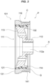
FIG. 3 is a longitudinal sectional side view of the torsional damper. -
FIG. 4 is a perspective view of the torsional damper illustrated in longitudinal section at a central position. -
FIG. 5 is a graph illustrating equivalent radiated power for each frequency. -
FIG. 6 is a graph illustrating the magnitude of the axial vibration of a vibration ring, which is caused by the axial vibration of the crankshaft, for each frequency. - An embodiment will be described with reference to the accompanying drawings. The present embodiment is an example of application to a pulley used in an inline 4-cylinder, 4-stroke engine. A description will be given on the following items.
- 1. Configuration
- (1) Engine
- (2) Basic configuration of the torsional damper
- (3) Stays
- 2. Operation and Effect
- (1) Basic operation and effect
- (2) Suppression of noise
- (a) Equivalent radiated power
- (b) Circumferential width of stays
- (c) Axial thickness of stays
- (d) Inclined shape of stays
- (e) Summarization
- 3. Modified Examples
- As illustrated in
FIG. 1 , a crankshaft 12 (rotating shaft) is rotatably installed to anengine 11. Thecrankshaft 12 is horizontally placed, and has atorsional damper 101, which is configured as a pulley P, fixed to one end thereof. - The
crankshaft 12 has acounterbalance 13 for each cylinder, apiston 16 being installed to apin 14 via a con-rod 15. Thepiston 16 is slidably accommodated in acylinder 17. Thepiston 16 slides in a vertical direction orthogonal to the axis of thecrankshaft 12. - As illustrated in
FIG. 2 andFIG. 4 , thetorsional damper 101 has anannular vibration ring 131 connected to ahub 111 via anelastic body 121, and is provided withbelt grooves 141 on the outer circumferential surface of thevibration ring 131. - The
hub 111 has, at a central position thereof, aboss 112 adapted to be fixed to thecrankshaft 12 of theengine 11, which is a rotating shaft, and also has arim 114 provided viastays 113 raised radially outward from theboss 112. - The
boss 112 is a member having a cylindrical shape, and has a mountinghole 112a at the center for fitting the rotating shaft therein. Thehub 111 is fixed to thecrankshaft 12 by fixing one end of thecrankshaft 12, which has been fitted in the mountinghole 112a, by abolt 21. In this state, theboss 112 rotates as thecrankshaft 12 rotates, with an axis A of theboss 112 being aligned with an axis X, which is the center of rotation of thecrankshaft 12. - The stays 113 are members interposed between the
boss 112 and therim 114 to connect theboss 112 and therim 114. Four stays 113 are provided, the individual stays being arranged at equal intervals on a circumference concentric with the axis A of theboss 112. Fourholes 115 are formed between the individual stays 113. Theseholes 115 are also arranged at equal intervals on the circumference concentric with the axis A of theboss 112. - The
rim 114 is an annular member extending along the axial direction of thehub 111 from the ends of thestays 113, and is placed concentrically with the axis A of theboss 112. Therefore, the outer circumferential surface of therim 114 is positioned on the circumference concentric with the axis A of theboss 112. The diameter of the outer circumferential surface of therim 114 is not constant, and the diameter becomes shorter at approximately the central position in the axial direction due to arim recess 116. Therim recess 116 is for forming a convolution C together with thevibration ring 131, the details of which will be described later. - The
hub 111 composed of theboss 112, thestays 113, and therim 114 is formed in one piece, using, for example, a metal as a material therefor. - The
elastic body 121 is an annular member having a uniform diameter, and interposed between therim 114 and thevibration ring 131 to elastically connect therim 114 and thevibration ring 131. Such anelastic body 121 is formed using, for example, rubber as a material therefor, and has a uniform thickness over the entire circumference. - The
vibration ring 131 is an annular member having the inner circumferential surface thereof facing the outer circumferential surface of therim 114 of theboss 112 via a gap G in which theelastic body 121 is interposed. Such avibration ring 131 functions as a mass (mass body) having a natural frequency due to the structure of being held via theelastic body 121. - A
ring projection 132, which matches the shape of therim recess 116 formed in the outer circumferential surface of therim 114, is formed on the inner circumferential surface of thevibration ring 131. Theserim recess 116 and thering projection 132 are provided over the entire circumferences of therim 114 and thevibration ring 131 in the circumferential direction thereof, configuring the convolution C. The convolution C enhances the sliding resistance of theelastic body 121 between therim 114 and thevibration ring 131, thus suppressing theelastic body 121 from being displaced or slipping out. - The
vibration ring 131 has a plurality ofbelt grooves 141 formed in the outer circumferential surface thereof in the circumferential direction. Thesebelt grooves 141 have a V-shaped cross section, and are structures around which an endless belt for power transmission is wound to drive various types of auxiliary equipment (none of which being illustrated). By providing thebelt grooves 141, thetorsional damper 101 serves as a pulley P. - The stays 113 of the
torsional damper 101 of the present embodiment have a circumferential width dimension that does not exceed one-quarter of the wavelength of a resonant frequency of thehub 111 in the axial direction, i.e., the direction of the axis A (refer toFIG. 1 ). - The resonant frequency of the
hub 111 is, for example, 3.7 kHz. The wavelength of the resonant frequency is:
- Therefore, the wavelength of the axial resonant frequency of the
hub 111 is approximately 0.092 m (92 mm). Consequently, thestays 113 have a circumferential width dimension not exceeding 23 mm, which is one-quarter of 92 mm. - The stays 113 of the present embodiment are thickened within a range in which the axial thickness dimension does not exceed one-half of the wavelength of the axial resonant frequency of the
hub 111. - As described above, the wavelength of the axial resonant frequency of the
hub 111 is approximately 92 mm. Thus, thestays 113 are thickened within a range not exceeding 46 mm, which is one-half of 92 mm. - The term "thickened" here means, for example, to set the thickness to be equal to or more than one-quarter of the wavelength of the axial resonant frequency of the
stays 113. In the case of this example, the axial thickness of thestays 113 is set to a range of 23 to 46 mm. - As another example, the term "thickened" means to set the thickness to be equal to or more than the circumferential width dimension. The circumferential width dimension of the
stays 113 is set to a range not exceeding 23 mm as described above. For example, if the circumferential width dimension of thestays 113 is set to 20 mm, then the axial thickness of thestays 113 is set to a range of 20 to 46 mm. - In simpler terms, the shape of the
stays 113 described above can be described as narrower in the circumferential direction and thicker in the axial direction in comparison with the stays included in a typical torsional damper. The thickness in the axial direction is greater in order to increase the rigidity of thestays 113. - In terms of securing rigidity, the
stays 113 of the present embodiment have an axially inclined shape (refer toFIGS. 2 and3 ). The front and back surfaces of thestays 113 are inclined at the same angle. In other words, the front and back surfaces of thestays 113, which are shaped to be inclined in the axial direction, have parallel portions. - In such a configuration, when the
crankshaft 12 rotates by starting theengine 11, thetorsional damper 101 also rotates. At this time, power is transmitted to auxiliary equipment, because thetorsional damper 101 also constitutes the pulley P. - The
torsional damper 101 has a natural frequency in the torsional direction because thevibration ring 131 functions as a mass (mass body). Therefore, in the case where thecrankshaft 12 rotates and torsional vibration is generated, the torsional vibration generated in thecrankshaft 12 can be absorbed and reduced by tuning the natural frequency of thetorsional damper 101 in the torsional direction to match the torsional resonant frequency. - In general, the torsional resonant frequency generated in the
crankshaft 12 is frequently approximately 300 to 600 Hz. Therefore, the natural frequency of thetorsional damper 101 in the torsional direction is also tuned to approximately 300 to 600 Hz in accordance with the torsional resonant frequency generated in thecrankshaft 12. - The
crankshaft 12 vibrates also in the direction of the axis X. Thus, thetorsional damper 101 also resonates in the direction of the axis A (hereinafter referred to as "axial direction") that coincides with the axis X. At this time, the axial resonant frequency of thevibration ring 131 is approximately several hundred Hz, which is approximately the same as the torsional vibration. - Meanwhile, the
hub 111 resonates in the axial direction at a higher frequency of several thousand Hz. When thehub 111 resonates at a higher frequency, the radiated sound emitted from thehub 111 inconveniently propagates as noise. - To understand the noise generated by the
hub 111, equivalent radiated power is assumed here. The equivalent radiated power is an index representing the degree of sound generated by an object. If the equivalent radiated power can be reduced, then the radiated sound emitted from thehub 111 can be reduced. - The calculation formula of the equivalent radiated power is as represented by expression (1).

- P: equivalent radiated power
- τ: radiation loss coefficient
- sv: sound velocity
- md: material density
- a: area
- v: vibration velocity
- The radiation loss coefficient τ is a coefficient depending on the shape of an object. The coefficient represents the degree of sound radiation, as can be imagined from the fact that, for example, a thin piano wire has weak sound radiation and a wide flat plate has strong sound radiation.
- The material density md is a material-dependent factor. The material density is determined by, for example, a spongy structure or a high-density material without bubbles.
- The area a means the projection area of a vibrating body.
- In the
torsional damper 101, thehub 111 is usually made of a metal such as cast iron, so that there is little room for ingenuity in terms of suppressing noise caused by radiated sound. Factors that are considered to be effective in suppressing noise are the radiation loss coefficient τ and the area a in terms of shape, and the vibration velocity v in terms of aspects other than shape. The radiated sound emitted from thehub 111 can be reduced by reducing the values of the three factors, namely, "the radiation loss coefficient τ," "the area a," and "the vibration velocity v." - However, it is difficult to devise measures to reduce the values of the above three factors for the
boss 112 and therim 114 of thehub 111. Therefore, in the present embodiment, the shape of thestays 113 is devised to reduce the values of the above three factors. - In the present embodiment, the circumferential width of the
stays 113 is smaller. As previously described, the width does not exceed one-quarter of the wavelength of the axial resonant frequency of thehub 111. This reduces both the radiation loss coefficient τ and the area a, and the equivalent radiated power P becomes smaller accordingly, thus reducing the radiated sound emitted from thehub 111. - A description will be given below in more detail.
- Depending on the dimensions of a vibrating body, the sound radiated from the vibrating body is divided into two types of frequencies, namely, frequencies that are efficiently radiated and frequencies that are inefficiently radiated. If the vibrating body is rectangular, then sound of a frequency having a wavelength shorter than the minimum width dimension of the vibrating body is radiated forward as air compressional waves. On the other hand, a frequency of a wavelength longer than the minimum width dimension causes a diffraction phenomenon in which surrounding air wraps around behind along the side surfaces of the vibrating body, and is not propagated to the surroundings as compressional waves. In particular, if the vibrating body has a minimum width of one-quarter of the wavelength, then there will be no radiated sound. This means that the radiation loss coefficient τ becomes extremely small.
- Therefore, in the present embodiment, the circumferential width of the
stays 113 is set to a width not exceeding one-quarter of the wavelength of the axial resonant frequency of thehub 111, e.g., a width of one-quarter. This makes it possible to suppress radiated sound generated by thehub 111. - In the present embodiment, the thickness of the
stays 113 is increased in the axial direction to increase the rigidity. Increasing the rigidity of thestays 113 decreases the axial vibration of thestays 113, causing the vibration state to shift toward higher frequencies. As a result, the vibration velocity v decreases, and the equivalent radiated power P is decreased, thus reducing the radiated sound emitted from thehub 111. - However, excessively increasing the thickness of the
stays 113 in the axial direction makes it difficult for the above-described diffraction phenomenon to take place. This is because the diffraction phenomenon is a phenomenon in which air wraps around behind along the side surfaces of the vibrating body, and therefore, if the side length of the vibrating body is long, it becomes difficult for air to wrap around behind. If this happens, then the radiation loss coefficient τ will not become sufficiently small. - In the present embodiment, therefore, the thickness of the
stays 113 is limited to a range in which the thickness does not exceed one-half of the wavelength of the axial resonant frequency of thehub 111, thus preventing the diffraction phenomenon from slowing down. - The rigidity in the axial direction can be significantly increased by inclining the
stays 113. In the present embodiment, the inclined shape increases the axial rigidity of thestays 113, thus achieving improved rigidity of thestays 113 rather than depending solely on the thickening. Consequently, the axial vibration of thestays 113 can be shifted toward higher frequencies while achieving the suppression of the radiated sound from thehub 111 attributable to the diffraction phenomenon. - The inclined shape of the
stays 113 becomes particularly important when it is difficult to thicken thestays 113 in the axial direction. As described above, the axial thickness of thestays 113 is limited to the range in which the thickness does not exceed one-half of the wavelength of the axial resonant frequency of thehub 111. However, a situation is assumed in which such a thickness cannot provide sufficient rigidity in the axial direction. The inclined shape of thestays 113 contributes to improving the rigidity of thestays 113 when thickening thestays 113 is limited. - Restricting the circumferential width dimension of the
stays 113 contributes to decreasing the radiation loss coefficient τ and the area a in the above-described expression (1) defining the equivalent radiated power P. This, on the other hand, lowers the rigidity of thestays 113, possibly leading to a disadvantageous situation for the vibration velocity v in expression (1). - In this respect, according to the present embodiment, the
stays 113 are thickened in the axial direction thereby to suppress or reduce an increase in the vibration velocity v. However, if the stays 113 are made excessively thickened in the axial direction, then it will be difficult for the diffraction phenomenon, in which air wraps around behind along the side surfaces of thestays 113, to take place, and the radiation loss coefficient τ will not become sufficiently small. - Therefore, according to the present embodiment, the thickening of the
stays 113 in the axial direction is restricted so as to prevent the diffraction phenomenon from slowing down. At this time, the inclined shape of thestays 113 suppresses a decrease in the rigidity in the axial direction, thus contributing to a reduction in the vibration velocity v. - As a result, the values of the three factors of "the radiation loss coefficient τ," "the area a," and "the vibration velocity v" are reduced in a well-balanced manner to reduce the equivalent radiated power P, thus making it possible to reduce the radiated sound emitted from the
hub 111. -
FIG. 5 and FIG. 6 are graphs illustrating simulation results. In these drawings, the simulation results of thetorsional damper 101 of the present embodiment are indicated by the solid lines, while the simulation results of a reference example are indicated by dashed lines. The reference example is a well-known torsional damper having no numeric range like the one for the present embodiment regarding the circumferential width and the axial thickness of thestays 113. - As illustrated in
FIG. 5 , it can be seen that, compared with the reference example, the equivalent radiated power of thetorsional damper 101 of the present embodiment is smaller in a wide frequency band ranging from 400 to 4000 Hz. Especially in the range of 1600 to 3200 Hz, which has a peak frequency slightly over 2500 Hz, the degree of decrease in the equivalent radiated power is markedly noticeable. The fact that there is no significant change in the equivalent radiated power over the entire frequency band can also be said to be an excellent characteristic in comparison with the reference example. -
FIG. 6 illustrates the magnitude of the axial vibration of thevibration ring 131 for each frequency. - As described above, when the axial vibration occurs in the
crankshaft 12, thevibration ring 131 of thetorsional damper 101 resonates in the axial direction at several hundred Hz. Referring to the simulation results of the reference example, it can be seen that the vibration ring resonates with peaks around 630 Hz, 1000 Hz, and 2500 Hz. At this time, in the reference example, the axial rigidity of the hub is low, so that the force due to the axial resonance of the vibration ring is expected to be transmitted to the rim positioned on the outer circumference of the hub through the elastic body, forcibly displacing the rim and thus inconveniently generating radiated sound. - In the present embodiment, the vibration generated in the
vibration ring 131 is lower than that in the reference example in every one of the above-mentioned three different frequency ranges. This is considered to be due to the high axial rigidity of thestays 113. Therefore, even when the forcible displacement force caused by the axial resonance of thevibration ring 131 is transmitted to therim 114, therim 114 does not easily deform, thus making it possible to reduce the radiated sound in the frequency bands. - In the implementation, various modifications and changes are allowed.
- For example, thickening the
stays 113 in the axial direction is not necessarily essential if the stays 113 are not required to have more rigidity than necessary. - The inclined shape of the
stays 113 is also not essential. If the stays 113 can be given sufficient rigidity without having an inclined shape, or if the stays 113 are not required to have more rigidity than necessary, then thestays 113 may have a straight shape extending from theboss 112 in a direction perpendicular to the axial direction. - Any other changes and modifications are allowed.
-
- 11
- engine
- 12
- crankshaft (rotating shaft)
- 13
- counterbalance
- 14
- pin
- 15
- con-rod
- 16
- piston
- 17
- cylinder
- 21
- bolt
- 101
- torsional damper
- 111
- hub
- 112
- boss
- 112a
- mounting hole
- 113
- stay
- 114
- rim
- 115
- hole
- 116
- rim recess
- 121
- elastic body
- 131
- vibration ring
- 132
- ring projection
- 141
- belt groove
- A
- axis (torsional damper)
- C
- convolution
- G
- gap
- P
- pulley
- X
- axis (crankshaft)
Claims (9)
- A torsional damper comprising:a hub in which a boss adapted to be fixed to a rotating shaft and an annular rim are integrally provided via a plurality of stays; andan annular vibration ring connected to an outer circumferential surface of the rim via an elastic body,wherein the stays have a circumferential width dimension that does not exceed one-quarter of a wavelength of an axial resonant frequency of the hub.
- The torsional damper according to claim 1,
wherein the stays are thickened within a range in which an axial thickness dimension of the stays does not exceed one-half of the wavelength of the axial resonant frequency of the hub. - The torsional damper according to claim 1,
wherein the stays have an axial thickness dimension that is set to a range from one-quarter to one-half of the wavelength of the axial resonant frequency of the hub. - The torsional damper according to claim 1,
wherein the stays have an axial thickness dimension that is set to a range in which the axial thickness dimension is equal to or more than a circumferential width dimension and equal to or less than one-half of the wavelength of the axial resonant frequency of the hub. - The torsional damper according to claim 1,wherein the stays are thickened in a range in which the axial thickness dimension of the stays does not exceed one-half of the wavelength of the axial resonant frequency of the hub, andthe stays have an axial thickness dimension that is set to a range from one-quarter to one-half of the wavelength of the axial resonant frequency of the hub.
- The torsional damper according to claim 1,wherein the stays are thickened in a range in which the axial thickness dimension of the stays does not exceed one-half of the wavelength of the axial resonant frequency of the hub, andthe stays have an axial thickness dimension that is set to a range in which the axial thickness dimension is equal to or more than a circumferential width dimension and equal to or less than one-half of the wavelength of the axial resonant frequency of the hub.
- The torsional damper according to claim 1,
wherein the circumferential width dimension of the stays is one-quarter of the wavelength of the axial resonant frequency of the hub. - The torsional damper according to any one of claims 1 to 7,
wherein the stays have an axially inclined shape. - The torsional damper according to claim 8,
wherein front and back surfaces of the stays, which are shaped to be inclined in the axial direction, have parallel portions.
Applications Claiming Priority (2)
| Application Number | Priority Date | Filing Date | Title |
|---|---|---|---|
| JP2022001967 | 2022-01-07 | ||
| PCT/JP2022/046805 WO2023132226A1 (en) | 2022-01-07 | 2022-12-20 | Torsional damper |
Publications (2)
| Publication Number | Publication Date |
|---|---|
| EP4461937A1 true EP4461937A1 (en) | 2024-11-13 |
| EP4461937A4 EP4461937A4 (en) | 2026-01-07 |
Family
ID=87073670
Family Applications (1)
| Application Number | Title | Priority Date | Filing Date |
|---|---|---|---|
| EP22918811.5A Pending EP4461937A4 (en) | 2022-01-07 | 2022-12-20 | TORSION DAMPER |
Country Status (5)
| Country | Link |
|---|---|
| US (1) | US12372148B2 (en) |
| EP (1) | EP4461937A4 (en) |
| JP (1) | JP7591668B2 (en) |
| CN (1) | CN118043569A (en) |
| WO (1) | WO2023132226A1 (en) |
Family Cites Families (35)
| Publication number | Priority date | Publication date | Assignee | Title |
|---|---|---|---|---|
| US3088332A (en) * | 1960-02-04 | 1963-05-07 | Simpson Mfg Company | Vibration damper |
| US3280654A (en) * | 1965-08-02 | 1966-10-25 | Simpson Mfg Company | Vibration damper |
| JPS61211552A (en) * | 1985-03-13 | 1986-09-19 | Toyota Motor Corp | Crank damper pulley structure for vehicle |
| US4794816A (en) * | 1985-10-15 | 1989-01-03 | Tokai Rubber Industries, Ltd. | Dual-type damper device |
| JPH02261953A (en) * | 1989-03-31 | 1990-10-24 | Tokai Rubber Ind Ltd | Rotor with damper |
| DE4025848A1 (en) * | 1990-08-16 | 1992-02-20 | Pahl Gummi Asbest | TURNING VIBRATION |
| JPH0544778A (en) * | 1991-08-09 | 1993-02-23 | Toyoda Gosei Co Ltd | Damper pulley |
| US5231893A (en) * | 1991-12-10 | 1993-08-03 | Simpson Industries, Inc. | Dual mode damper |
| JPH05202987A (en) | 1992-01-27 | 1993-08-10 | Nissan Motor Co Ltd | Engine crank pulley structure |
| DE4328153C2 (en) * | 1993-08-21 | 1996-11-28 | Freudenberg Carl Fa | Ring-shaped machine part and method for its production |
| JPH07259962A (en) * | 1994-03-18 | 1995-10-13 | Toyoda Gosei Co Ltd | Damper pulley and manufacture thereof |
| JPH11109979A (en) | 1997-09-30 | 1999-04-23 | Nok Megurasutikku Kk | Muffling device |
| JPH11159576A (en) * | 1997-11-28 | 1999-06-15 | Nok Megurasutikku Kk | Damper |
| JP5118792B2 (en) * | 2000-01-14 | 2013-01-16 | 株式会社フコク | Damper and manufacturing method thereof |
| JP2002286094A (en) * | 2000-12-25 | 2002-10-03 | Maruyasu Industries Co Ltd | Vibration controller for torsional vibration body and damper pulley |
| JP2002276738A (en) * | 2001-03-13 | 2002-09-25 | Fukoku Co Ltd | Torsion damper |
| ITTO20020622A1 (en) * | 2002-07-16 | 2004-01-16 | Dayco Europe Srl | INTEGRATED PULLEY-TORSIONAL DAMPER GROUP |
| JP2004125108A (en) * | 2002-10-04 | 2004-04-22 | Nok Corp | Method for manufacturing torsional damper |
| JP2004225829A (en) * | 2003-01-24 | 2004-08-12 | Nok Corp | Method of manufacturing torsional damper |
| US7047644B2 (en) * | 2003-02-21 | 2006-05-23 | The Gates Corporation | Crankshaft damper and method of assembly |
| JP4572739B2 (en) * | 2005-05-20 | 2010-11-04 | 株式会社ジェイテクト | Rotation fluctuation absorbing damper pulley |
| JP4329788B2 (en) * | 2006-07-18 | 2009-09-09 | トヨタ自動車株式会社 | How to adjust engine rotation balance |
| US20090145261A1 (en) * | 2007-12-06 | 2009-06-11 | Richard Obeshaw | Single mass dual mode crankshaft damper with tuned hub |
| KR20120102879A (en) * | 2011-03-09 | 2012-09-19 | 한국후꼬꾸 주식회사 | Damper pulley |
| KR101714208B1 (en) * | 2015-09-03 | 2017-03-08 | 현대자동차주식회사 | Independence Rotational Inertia Mass type Torsional Damper and Crankshaft thereby |
| EP3385567B8 (en) * | 2015-12-04 | 2020-12-30 | NOK Corporation | Sealing structure with annular pocket and sealing apparatus |
| JP6605936B2 (en) | 2015-12-10 | 2019-11-13 | Nok株式会社 | Pulley noise reduction device |
| ITUA20163801A1 (en) * | 2016-05-25 | 2017-11-25 | Dayco Europe Srl | INTEGRATED GROUP TORSIONAL DAMPING PULLEY |
| WO2018194162A1 (en) * | 2017-04-21 | 2018-10-25 | Nok株式会社 | Rubber composition for torsional damper, and torsional damper |
| US10591042B2 (en) * | 2017-07-28 | 2020-03-17 | GM Global Technology Operations LLC | Damper pulley |
| JP6811702B2 (en) * | 2017-12-19 | 2021-01-13 | Nok株式会社 | Tortional damper |
| WO2019194088A1 (en) * | 2018-04-02 | 2019-10-10 | Nok株式会社 | Air flow generation structural body and sealing structure |
| JP7159729B2 (en) | 2018-09-13 | 2022-10-25 | いすゞ自動車株式会社 | crank pulley |
| JP2021146740A (en) * | 2020-03-16 | 2021-09-27 | 本田技研工業株式会社 | Vehicle control device, vehicle and vehicle control method |
| US20210402504A1 (en) * | 2020-06-26 | 2021-12-30 | GM Global Technology Operations LLC | Torsional damper and method of welding parts having dissimilar materials |
-
2022
- 2022-12-20 US US18/694,014 patent/US12372148B2/en active Active
- 2022-12-20 CN CN202280066539.XA patent/CN118043569A/en active Pending
- 2022-12-20 EP EP22918811.5A patent/EP4461937A4/en active Pending
- 2022-12-20 JP JP2023572407A patent/JP7591668B2/en active Active
- 2022-12-20 WO PCT/JP2022/046805 patent/WO2023132226A1/en not_active Ceased
Also Published As
| Publication number | Publication date |
|---|---|
| US12372148B2 (en) | 2025-07-29 |
| JP7591668B2 (en) | 2024-11-28 |
| US20250146567A1 (en) | 2025-05-08 |
| EP4461937A4 (en) | 2026-01-07 |
| CN118043569A (en) | 2024-05-14 |
| JPWO2023132226A1 (en) | 2023-07-13 |
| WO2023132226A1 (en) | 2023-07-13 |
Similar Documents
| Publication | Publication Date | Title |
|---|---|---|
| EP2212584B1 (en) | Flywheel assembly | |
| EP0220871B1 (en) | Dual-type damper device | |
| WO1994027061A1 (en) | Dual mode damper | |
| US20080034918A1 (en) | Multi-mode vibration damper having a spoked hub | |
| KR100430252B1 (en) | Damper mechanism | |
| US20020128073A1 (en) | Damper mechanism | |
| KR20070026192A (en) | Torsion damping device or separation device with wire spring wound in drive disk | |
| JP2002340095A (en) | Damper mechanism | |
| US12372148B2 (en) | Torsional damper | |
| JP7159729B2 (en) | crank pulley | |
| US20150240711A1 (en) | Connecting rod structure of engine | |
| US5950791A (en) | Damper disk assembly | |
| JP4016801B2 (en) | Torsional damper | |
| JP7830165B2 (en) | Torsion damper | |
| JP2024068917A (en) | Dynamic vibration absorber | |
| JPH0531311Y2 (en) | ||
| JPH06506515A (en) | Devices inside an internal combustion engine | |
| JP2024060849A (en) | Torsional Damper | |
| JPH10227333A (en) | Dynamic damper | |
| KR100510206B1 (en) | Structure of noize reduction for geared reducer | |
| US20250237301A1 (en) | Torsional damper | |
| JP3888581B2 (en) | Dynamic damper | |
| JP3534126B2 (en) | Torque fluctuation absorption damper | |
| JPH0539228Y2 (en) | ||
| JP2003172403A (en) | Crank pulley |
Legal Events
| Date | Code | Title | Description |
|---|---|---|---|
| STAA | Information on the status of an ep patent application or granted ep patent |
Free format text: STATUS: THE INTERNATIONAL PUBLICATION HAS BEEN MADE |
|
| PUAI | Public reference made under article 153(3) epc to a published international application that has entered the european phase |
Free format text: ORIGINAL CODE: 0009012 |
|
| STAA | Information on the status of an ep patent application or granted ep patent |
Free format text: STATUS: REQUEST FOR EXAMINATION WAS MADE |
|
| 17P | Request for examination filed |
Effective date: 20240320 |
|
| AK | Designated contracting states |
Kind code of ref document: A1 Designated state(s): AL AT BE BG CH CY CZ DE DK EE ES FI FR GB GR HR HU IE IS IT LI LT LU LV MC ME MK MT NL NO PL PT RO RS SE SI SK SM TR |
|
| DAV | Request for validation of the european patent (deleted) | ||
| DAX | Request for extension of the european patent (deleted) | ||
| A4 | Supplementary search report drawn up and despatched |
Effective date: 20251209 |
|
| RIC1 | Information provided on ipc code assigned before grant |
Ipc: F02B 67/06 20060101AFI20251203BHEP Ipc: F16F 15/126 20060101ALI20251203BHEP Ipc: F16H 55/36 20060101ALI20251203BHEP |