EP4461920A1 - Gripper, rock drilling unit and method - Google Patents
Gripper, rock drilling unit and method Download PDFInfo
- Publication number
- EP4461920A1 EP4461920A1 EP23172251.3A EP23172251A EP4461920A1 EP 4461920 A1 EP4461920 A1 EP 4461920A1 EP 23172251 A EP23172251 A EP 23172251A EP 4461920 A1 EP4461920 A1 EP 4461920A1
- Authority
- EP
- European Patent Office
- Prior art keywords
- gripper
- piston
- drilling
- gripping
- rock
- Prior art date
- Legal status (The legal status is an assumption and is not a legal conclusion. Google has not performed a legal analysis and makes no representation as to the accuracy of the status listed.)
- Granted
Links
Images

Classifications
-
- E—FIXED CONSTRUCTIONS
- E21—EARTH OR ROCK DRILLING; MINING
- E21B—EARTH OR ROCK DRILLING; OBTAINING OIL, GAS, WATER, SOLUBLE OR MELTABLE MATERIALS OR A SLURRY OF MINERALS FROM WELLS
- E21B7/00—Special methods or apparatus for drilling
- E21B7/02—Drilling rigs characterised by means for land transport with their own drive, e.g. skid mounting or wheel mounting
-
- E—FIXED CONSTRUCTIONS
- E21—EARTH OR ROCK DRILLING; MINING
- E21B—EARTH OR ROCK DRILLING; OBTAINING OIL, GAS, WATER, SOLUBLE OR MELTABLE MATERIALS OR A SLURRY OF MINERALS FROM WELLS
- E21B19/00—Handling rods, casings, tubes or the like outside the borehole, e.g. in the derrick; Apparatus for feeding the rods or cables
- E21B19/10—Slips; Spiders ; Catching devices
-
- E—FIXED CONSTRUCTIONS
- E21—EARTH OR ROCK DRILLING; MINING
- E21B—EARTH OR ROCK DRILLING; OBTAINING OIL, GAS, WATER, SOLUBLE OR MELTABLE MATERIALS OR A SLURRY OF MINERALS FROM WELLS
- E21B15/00—Supports for the drilling machine, e.g. derricks or masts
- E21B15/003—Supports for the drilling machine, e.g. derricks or masts adapted to be moved on their substructure, e.g. with skidding means; adapted to drill a plurality of wells
-
- E—FIXED CONSTRUCTIONS
- E21—EARTH OR ROCK DRILLING; MINING
- E21B—EARTH OR ROCK DRILLING; OBTAINING OIL, GAS, WATER, SOLUBLE OR MELTABLE MATERIALS OR A SLURRY OF MINERALS FROM WELLS
- E21B19/00—Handling rods, casings, tubes or the like outside the borehole, e.g. in the derrick; Apparatus for feeding the rods or cables
- E21B19/14—Racks, ramps, troughs or bins, for holding the lengths of rod singly or connected; Handling between storage place and borehole
-
- E—FIXED CONSTRUCTIONS
- E21—EARTH OR ROCK DRILLING; MINING
- E21B—EARTH OR ROCK DRILLING; OBTAINING OIL, GAS, WATER, SOLUBLE OR MELTABLE MATERIALS OR A SLURRY OF MINERALS FROM WELLS
- E21B19/00—Handling rods, casings, tubes or the like outside the borehole, e.g. in the derrick; Apparatus for feeding the rods or cables
- E21B19/16—Connecting or disconnecting pipe couplings or joints
- E21B19/161—Connecting or disconnecting pipe couplings or joints using a wrench or a spinner adapted to engage a circular section of pipe
- E21B19/163—Connecting or disconnecting pipe couplings or joints using a wrench or a spinner adapted to engage a circular section of pipe piston-cylinder actuated
-
- E—FIXED CONSTRUCTIONS
- E21—EARTH OR ROCK DRILLING; MINING
- E21B—EARTH OR ROCK DRILLING; OBTAINING OIL, GAS, WATER, SOLUBLE OR MELTABLE MATERIALS OR A SLURRY OF MINERALS FROM WELLS
- E21B19/00—Handling rods, casings, tubes or the like outside the borehole, e.g. in the derrick; Apparatus for feeding the rods or cables
- E21B19/24—Guiding or centralising devices for drilling rods or pipes
-
- E—FIXED CONSTRUCTIONS
- E21—EARTH OR ROCK DRILLING; MINING
- E21B—EARTH OR ROCK DRILLING; OBTAINING OIL, GAS, WATER, SOLUBLE OR MELTABLE MATERIALS OR A SLURRY OF MINERALS FROM WELLS
- E21B7/00—Special methods or apparatus for drilling
- E21B7/02—Drilling rigs characterised by means for land transport with their own drive, e.g. skid mounting or wheel mounting
- E21B7/022—Control of the drilling operation; Hydraulic or pneumatic means for activation or operation
-
- E—FIXED CONSTRUCTIONS
- E21—EARTH OR ROCK DRILLING; MINING
- E21B—EARTH OR ROCK DRILLING; OBTAINING OIL, GAS, WATER, SOLUBLE OR MELTABLE MATERIALS OR A SLURRY OF MINERALS FROM WELLS
- E21B7/00—Special methods or apparatus for drilling
- E21B7/02—Drilling rigs characterised by means for land transport with their own drive, e.g. skid mounting or wheel mounting
- E21B7/025—Rock drills, i.e. jumbo drills
-
- F—MECHANICAL ENGINEERING; LIGHTING; HEATING; WEAPONS; BLASTING
- F15—FLUID-PRESSURE ACTUATORS; HYDRAULICS OR PNEUMATICS IN GENERAL
- F15B—SYSTEMS ACTING BY MEANS OF FLUIDS IN GENERAL; FLUID-PRESSURE ACTUATORS, e.g. SERVOMOTORS; DETAILS OF FLUID-PRESSURE SYSTEMS, NOT OTHERWISE PROVIDED FOR
- F15B11/00—Servomotor systems without provision for follow-up action ; Circuits therefor
- F15B11/08—Servomotor systems without provision for follow-up action ; Circuits therefor with only one servomotor
- F15B11/12—Servomotor systems without provision for follow-up action ; Circuits therefor with only one servomotor providing distinct intermediate positions; with step-by-step action
- F15B11/121—Servomotor systems without provision for follow-up action ; Circuits therefor with only one servomotor providing distinct intermediate positions; with step-by-step action providing distinct intermediate positions
- F15B11/123—Servomotor systems without provision for follow-up action ; Circuits therefor with only one servomotor providing distinct intermediate positions; with step-by-step action providing distinct intermediate positions by means of actuators with fluid-operated stops
-
- E—FIXED CONSTRUCTIONS
- E21—EARTH OR ROCK DRILLING; MINING
- E21B—EARTH OR ROCK DRILLING; OBTAINING OIL, GAS, WATER, SOLUBLE OR MELTABLE MATERIALS OR A SLURRY OF MINERALS FROM WELLS
- E21B19/00—Handling rods, casings, tubes or the like outside the borehole, e.g. in the derrick; Apparatus for feeding the rods or cables
- E21B19/20—Combined feeding from rack and connecting, e.g. automatically
Definitions
- the invention relates to a gripper for handling rock drilling tools used in rock drilling.
- the gripper comprises at least one gripping jaw movable by means of at least one hydraulic cylinder.
- the invention further relates to a rock drilling unit provided with a gripper, and to a method of handling rock drilling tools.
- drill holes are drilled by means of rock drilling units comprising rock drilling machines arranged movably on feed beams.
- Drilling tools are connectable to the drilling machines by means of screw joints.
- the drilling tools may comprise one or more drill rods or tubes and a drill bit.
- the feed beams are provided with retainers for holding the drilling tools immovable when coupling and decoupling the drilling tools.
- the retainers comprise gripping jaws which are moved by means of hydraulic cylinders.
- An object of the invention is to provide a novel and improved gripper and method for handling rock drilling tools.
- the invention further relates to a drilling unit provided with a retainer and utilizing the disclosed gripper.
- the gripper according to the invention is characterized by the characterizing features of the first independent apparatus claim.
- the rock drilling unit according to the invention is characterized by the characterizing features of the second independent apparatus claim.
- the method according to the invention is characterized by the charactering features and steps of the independent method claim.
- the gripper for handling rock drilling tools comprises at least one hydraulic cylinder and at least one gripping jaw movable by means of the hydraulic cylinder towards and away from the drilling tool arranged to pass through the gripper.
- the hydraulic cylinder comprises at least one adjusting piston having a first operating position with a first fixed stoppage and a second operating position with a fixed second stoppage.
- the adjusting piston is configured to limit movement length of the piston rod at one of the first and second operating positions to provide the at least one gripping jaw an intermediate position between extreme movement positions of the at least one gripping jaw.
- the adjusting piston is a pressure operated element by means of which the hydraulic cylinder is provided with three accurate piston rod positions instead of conventional two positions.
- the adjusting piston is configured to move between two fixed stoppage surfaces whereby the adjusting piston has two operational positions at its extreme movement directions. Thus, the adjusting piston has no intermediate positions between the extreme fixed positions. At the fixed operational positions, the adjusting piston is forced against physical stoppage surfaces limiting the movement range. Locations of the stoppage surfaces define two operational positions for the adjusting piston and thereby also define two protruding lengths for the piston rod.
- An advantage of the disclosed solution is that by means of the adjusting piston the hydraulic cylinder can be controlled in a more versatile manner and the gripper can be utilized better. Further, the fixed positions define accurate piston rod protrusion lengths. The movements of the piston are simple to control.
- the gripper is also applicable for handling of drilling tools with different dimensions, and it can be retrofitted to existing drilling units.
- the gripper is provided with three operational modes wherein each mode has different protruding length for the piston rod and wherein magnitude of the protruding length of the piston rod is configured to define position of the at least one gripping jaw in relation to the rock drilling tool being handled.
- the piston has fully retracted or shortened position, and two different extended or lengthened positions which define the operational modes.
- the gripper has an open mode, a guiding mode, and a gripping mode.
- the piston rod moves to an extreme first protruding length in response to selection of the open mode and moves to an opposite extreme second protruding length in response selection of the gripping mode. Further, the piston rod is moved to an intermediate position between the extreme first and second protruding lengths in response to selection of the guiding mode.
- the open mode is utilized to provide the gripper with no grip and no contact whatsoever to the rock drilling tool.
- the guiding mode there is a kind of soft grip wherein the at least one gripping jaw is close to the outer surface of the drilling tool but does not press against it.
- a gripping mode strong grip against the rock drilling tool is provided. Movement of the drilling tool in the gripping mode is prevented with the strong grip.
- the structure and mechanics of the gripper can be designed in several alternative ways, whereby the maximum protruding length of the piston rod may be implemented either for producing the open mode or the gripping mode.
- the minimum protruding length of the piston rod which can be utilized for either producing the open mode or the gripping mode depending on the structure of the gripper.
- At least the guiding mode is defined by the adjusting piston.
- the piston rod has minimum protruding length in response to selection of the open mode; and the piston rod has maximum protruding length in response to selection of the gripping mode.
- the gripper has an idle mode wherein all pressure spaces of the hydraulic cylinder are connected to at least one tank pressure line.
- the piston rod is free to move in either of its movement directions under influence of external forces.
- the cylinder is then pressure free.
- the adjusting piston is a sleeve-like piece mounted movably on the piston rod.
- the adjusting piston is a kind of a floating piston which can slide on the piston rod and move towards to its two extreme control positions.
- the adjusting piston has a first face surface facing towards the piston and being provided with a ring shaped axial protrusion facing towards the piston and diameter of which is minor than outer diameter of the adjusting piston whereby the axial protrusion is configured to serve as an axial stoppage surface for the piston when the adjusting piston is moved to its extreme position towards the piston.
- the piston is provided with a second axial protrusion facing towards the adjusting piston.
- the hydraulic cylinder comprises three working pressure spaces wherein prevailing pressure is adjustable for moving the piston and for moving relative position of piston and the adjusting piston.
- the hydraulic cylinder comprises a first working pressure space on the piston side, a second working pressure space and a third working pressure space both being on the rod side.
- the second working pressure space is located between the piston and the adjusting piston, whereas the third working pressure space is located on an opposite side of the adjusting piston compared to the second working pressure space.
- the working pressure spaces are connectable to pressure lines and discharge lines by controlling control valves.
- the gripper is a part of a retainer comprising two hydraulic cylinders mounted on opposite sides in relation to the drilling tool arranged to pass through the retainer. Piston rods of the hydraulic cylinders are facing towards each other, and the retainer comprises two gripping jaws which are mounted to distal ends of the piston rods.
- the two hydraulic cylinders are controlled in a simultaneous and synchronous manner so that their piston rods move in similar manner.
- the two hydraulic cylinders are controlled independently in relation to each other. Then a first hydraulic cylinder may be controlled to move a first gripping jaw close to the drilling tool being handled i.e., to move to a base position, and a second hydraulic cylinder may be controlled to move a second gripping jaw to the positions being in accordance with principles of the open mode, guiding mode and gripping mode.
- the gripper is part of a retainer comprising an articulated lever mechanism configured to transmit the movements of the hydraulic cylinder to the gripping jaws mounted to lever arms of the lever mechanism.
- one hydraulic cylinder can move the lever mechanism and provide the disclosed movements and modes for the gripping jaws.
- the gripper is part of a rod handler for moving the rock drilling tools to drilling axis and comprising one movable gripping jaw movable in relation to a fixed counterpart.
- the disclosed solution relates also to a rock drilling unit for drilling holes to rock surfaces.
- the rock drilling unit comprises: a feed beam; a rock drilling machine mounted movably on the feed beam; and a retainer at a front end portion of the feed beam and being capable to selectively grip to a drilling tool mountable to the rock drilling machine.
- the retainer is provided with a gripper which is in accordance with the features and embodiments disclosed in this document.
- the disclosed solution relates also to a rock drilling unit for drilling holes to rock surfaces.
- the rock drilling unit comprises: a feed beam; a rock drilling machine mounted movably on the feed beam; and a rod handler for moving drilling tools between a tool magazine and drilling axis; and wherein the rod handler is provided with a gripper being capable to selectively grip to the drilling tools mountable to the rock drilling machine.
- the gripper of the rod handler is in accordance with the features and embodiments disclosed in this document.
- the disclosed solution relates also to a method of handling a drilling tool on a rock drilling unit.
- the method comprises: drilling a drill hole to the rock surface by means of the rock drilling unit; gripping the drilling tool by means of at least one gripping jaw of a gripper mounted on the drilling unit; and moving the at least one gripping jaw in relation to the drilling tool by means of at least one hydraulic cylinder of the gripper.
- the method further comprises using the gripper as disclosed in this document and providing the gripper with at least three operational modes with different relative positions of the at least one gripping jaw.
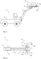
- Figure 1 discloses a rock drilling rig 1 comprising a carrier 2, at least one drilling boom 3 and a drilling unit 4 at a distal end portion of the boom 3.
- the drilling unit 4 comprises a feed beam 5 and a rock drilling machine 6 supported to the feed beam 5 and arranged to be move longitudinally along drilling axis DA by means of a feed device.
- Drilling tools 7, such as drill rods 7a and drill bits 7b may be fastened to the drilling machine 6 for directing impact pulses and rotation to rock surface being drilled.
- At a front end portion of the feed beam may be a retainer 8, for supporting the drilling tools 7 stationary on the drilling axis DA when the drilling tools 7 are mounted and dismounted.
- the retainer 8 comprises a gripper 9 which is in accordance with this document.
- Figure 2 discloses a retainer 8 at one end portion of a feed beam 5.
- a rock drilling machine 6 can be moved on the feed beam 5 and drilling tools 7 connected to the drilling machine 6 are on drilling axis DA and are passing through a gripper 9 being part of the retainer 8.
- the gripper 9 comprises two hydraulic cylinders 10a, 10b mounted on opposite sides in relation to the drilling tool 7. Piston rods 11a, 11b of the hydraulic cylinders 10a, 10b are facing towards each other and are provided with two gripping jaws 12a, 12b.
- the hydraulic cylinders 10a, 10b comprise the features and functionality disclosed in this document.
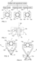
- Figure 3 discloses that a gripper 9 may be provided with at least three modes.
- the modes may be an open mode M1, gripping mode M2 and guiding mode M3.
- a drilling tool 7 passing the through gripping jaws 12, 12b is a drilling rod 7a in Figure 3 .
- the gripper 9 In the open mode M1 the gripper 9 is controlled so that no grip and no contact occur between gripping jaws 12a, 12b and the drilling rod 7a.
- the guiding mode M3 there is a kind of soft grip wherein the gripping jaws 12a, 12b are close to the outer surface of the drilling tool but does not press against it.
- a clearance C1 is greater than a clearance C2 in the guiding mode M3.
- Figure 4 discloses a retainer 8 provided with a gripper 9 with one hydraulic cylinder 10a for moving one movable gripping jaw 12a.
- the gripping jaw 12a is movable in relation to an immovably arranged gripping jaw 12b in a manner disclosed in this document for providing the operational modes.
- Figures 5 and 6 disclose possible mechanisms for grippers 9 for moving two gripping jaws 12, 12b towards and away from a drilling tool 7.
- one dedicated hydraulic cylinder 10 is sufficient to produce required movements for the gripping jaws 12a, 12b since the hydraulic cylinders 10 are arranged between mechanical arms 13a, 13b connected to each other turnable around joints 14.
- Figure 7 further shows that the gripper 9 may comprise one fixed gripping jaw 12a and one movable gripping jaw 12b. Movement of the gripping jaw 12b is generated either directly or indirectly by means of a hydraulic cylinder disclosed in this document.
- the disclosed gripper 9 with one movable gripping jaw can be utilized in a versatile manner for handling different tools and pieces used in drilling process.
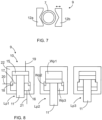
- Figure 8 discloses an example structure of a hydraulic cylinder 10 of a gripper 9.
- the gripper 9 is provided with three different protruding length positions Lp1 for a piston rod 11 movable by means of a piston 15. Magnitude of the protruding length of the piston rod 11 defines position of a gripping jaw, which is not shown.
- the piston rod 11 may have a fully retracted position (left, Lp1), a partly extended intermediate position (right, Lp3) and a fully extended position (middle, Lp2) which positions define operational modes M1 - M3 of the gripper 9.
- There is an adjusting piston 16 for effecting to the movements of the piston 15 and the piston rod 11. At least the intermediate length position Lp3 on the right side is defined by means of the adjusting piston 16.
- the adjusting piston 16 is a sleeve-like piece mounted movably on the piston rod 11. Then the adjusting piston 16 may be a kind of a floating piston which can slide on the piston rod 11 and move towards to its two extreme control positions.
- the adjusting piston 16 has a first face surface 17 facing towards the piston 15 and being provided with a ring shaped axial protrusion 18 facing towards the piston 15. Diameter of axial protrusion 18 is minor than outer diameter of the adjusting piston 16 whereby the axial protrusion 18 is able to serve as an axial stoppage surface for the piston 15 when the adjusting piston 16 is moved to its extreme position towards the piston 15.
- the hydraulic cylinder 10 comprises three working pressure spaces Wp1, Wp2 and Wp3 wherein prevailing pressure is adjustable for moving the piston 15 and for moving relative position of the piston 15 and the adjusting piston 16.
- the first working pressure space Wp1 is on the piston side
- the second working pressure space Wp2 is located between the piston 15 and the adjusting piston 16
- the third working pressure space Wp3 is located on an opposite side of the adjusting piston compared to the second working pressure space Wp2.
- the working pressure spaces Wp1 - Wp3 are connected to one or more pressure fluid lines 19, 20 and 21.
- the piston 11 is in the length position Lp1 moved to its upmost extreme position, and in the length position Lp2 the piston 15 is moved to its lowermost extreme position against the adjusting piston 16 which is also at its lowermost extreme position.
- the adjusting piston 16 is moved to its upmost extreme position and the piston 15 is set against the axial protrusion 18 so that the intermediate position is achieved.
- Figure 8 clearly discloses that the adjusting piston 16 moves between its extreme axial positions against fixed surfaces of a body 22 without any intermediate positions.
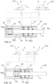
- Figures 9 - 12 discloses a structure of a hydraulic piston 10 and a hydraulic circuit for operating it and providing different length positions Lp1 - Lp3 for a piston rod 11.
- the hydraulic circuit may comprise two control valves, a first control valve Cv1 and a second control valve Cv2 by means of which pressure fluid is fed and discharged to and from working pressure space Wp1 - Wp3 for moving a piston 15 and an adjusting piston 16 to desired positions.
- the control valves Cv1 and Cv2 are connected to pressure fluid lines 19, 20 and 21.
- the first control valve Cv1 connects a first working pressure space Wp1 to a tank T whereby the piston 15 can move to its left most position since the second control valve Cv2 directs pressure fluid to the second working pressure space Wp2. Fluid flow from the third working pressure space Wp3 to tank T is prevented. Then the piston rod 11 is retracted and has its shortest possible position.
- a first movement direction is marked as A and an opposite second movement direction is marked as B.
- the piston rod 11 has its intermediate position wherein the adjusting piston 16 limits movement of the piston 15 to the right.
- the second control valve Cv2 has changed its position and directs pressure fluid flow to the third working pressure space Wp3 and connects the second working pressure space Wp2 to the tank T.
- piston rod 11 is in the same length position Lp1 as in Figure 9 but is free to move in either of its movement directions since the second control valve Cv2 is moved to its central position. All the working pressure space Wp1 - Wp3 are connected to the tank T by means of the control valves Cv1 and Cv2.
- Figure 13 discloses a gripper 9 arranged in connection with a rod handling apparatus 23.
- the apparatus 23 may comprise a magazine 24 for storing several drill rods 7a.
- the magazine 24 may be rotatably mounted or may comprise other means for indexing.
- the manipulator 25 can move the drill rods 7a between the magazine 24 and drilling axis DA of a rock drilling apparatus 6.
- the gripper 9 is disclosed more detailed in Figure 14 wherein is showed that the gripper 9 may comprise one movable gripping jaw 12a and one immovable gripping jaw 12b, which may be structural part of the manipulator 25 or may be separate part mounted to the manipulator 25.
- a hydraulic cylinder 10 for moving the movable gripping jaw 12a is in accordance with the features and embodiments disclosed in this document and may be configured to provide the gripper 9 with the gripping mode, guiding mode and the open mode.
Landscapes
- Engineering & Computer Science (AREA)
- Geology (AREA)
- Mining & Mineral Resources (AREA)
- Life Sciences & Earth Sciences (AREA)
- Physics & Mathematics (AREA)
- Fluid Mechanics (AREA)
- General Life Sciences & Earth Sciences (AREA)
- Environmental & Geological Engineering (AREA)
- Geochemistry & Mineralogy (AREA)
- Mechanical Engineering (AREA)
- Chemical & Material Sciences (AREA)
- Analytical Chemistry (AREA)
- General Engineering & Computer Science (AREA)
- Earth Drilling (AREA)
- Actuator (AREA)
Abstract
Description
- The invention relates to a gripper for handling rock drilling tools used in rock drilling. The gripper comprises at least one gripping jaw movable by means of at least one hydraulic cylinder.
- The invention further relates to a rock drilling unit provided with a gripper, and to a method of handling rock drilling tools.
- The field of the invention is defined more specifically in the preambles of the independent claims.
- In mines, construction sites and at other work areas drill holes are drilled by means of rock drilling units comprising rock drilling machines arranged movably on feed beams. Drilling tools are connectable to the drilling machines by means of screw joints. The drilling tools may comprise one or more drill rods or tubes and a drill bit. The feed beams are provided with retainers for holding the drilling tools immovable when coupling and decoupling the drilling tools. Typically the retainers comprise gripping jaws which are moved by means of hydraulic cylinders. There are several different retainer designs. However, the present solutions have shown to contain some disadvantages.
- An object of the invention is to provide a novel and improved gripper and method for handling rock drilling tools. The invention further relates to a drilling unit provided with a retainer and utilizing the disclosed gripper.
- The gripper according to the invention is characterized by the characterizing features of the first independent apparatus claim.
- The rock drilling unit according to the invention is characterized by the characterizing features of the second independent apparatus claim.
- The method according to the invention is characterized by the charactering features and steps of the independent method claim.
- An idea of the disclosed solution is that the gripper for handling rock drilling tools comprises at least one hydraulic cylinder and at least one gripping jaw movable by means of the hydraulic cylinder towards and away from the drilling tool arranged to pass through the gripper. The hydraulic cylinder comprises at least one adjusting piston having a first operating position with a first fixed stoppage and a second operating position with a fixed second stoppage. The adjusting piston is configured to limit movement length of the piston rod at one of the first and second operating positions to provide the at least one gripping jaw an intermediate position between extreme movement positions of the at least one gripping jaw.
- In other words, the adjusting piston is a pressure operated element by means of which the hydraulic cylinder is provided with three accurate piston rod positions instead of conventional two positions.
- The adjusting piston is configured to move between two fixed stoppage surfaces whereby the adjusting piston has two operational positions at its extreme movement directions. Thus, the adjusting piston has no intermediate positions between the extreme fixed positions. At the fixed operational positions, the adjusting piston is forced against physical stoppage surfaces limiting the movement range. Locations of the stoppage surfaces define two operational positions for the adjusting piston and thereby also define two protruding lengths for the piston rod.
- An advantage of the disclosed solution is that by means of the adjusting piston the hydraulic cylinder can be controlled in a more versatile manner and the gripper can be utilized better. Further, the fixed positions define accurate piston rod protrusion lengths. The movements of the piston are simple to control.
- The gripper is also applicable for handling of drilling tools with different dimensions, and it can be retrofitted to existing drilling units.
- According to an embodiment, the gripper is provided with three operational modes wherein each mode has different protruding length for the piston rod and wherein magnitude of the protruding length of the piston rod is configured to define position of the at least one gripping jaw in relation to the rock drilling tool being handled. In other words, the piston has fully retracted or shortened position, and two different extended or lengthened positions which define the operational modes.
- According to an embodiment, the gripper has an open mode, a guiding mode, and a gripping mode. The piston rod moves to an extreme first protruding length in response to selection of the open mode and moves to an opposite extreme second protruding length in response selection of the gripping mode. Further, the piston rod is moved to an intermediate position between the extreme first and second protruding lengths in response to selection of the guiding mode. In other words, the open mode is utilized to provide the gripper with no grip and no contact whatsoever to the rock drilling tool. In the guiding mode there is a kind of soft grip wherein the at least one gripping jaw is close to the outer surface of the drilling tool but does not press against it. In a gripping mode strong grip against the rock drilling tool is provided. Movement of the drilling tool in the gripping mode is prevented with the strong grip.
- According to an embodiment, the structure and mechanics of the gripper can be designed in several alternative ways, whereby the maximum protruding length of the piston rod may be implemented either for producing the open mode or the gripping mode. The same applies also for the minimum protruding length of the piston rod which can be utilized for either producing the open mode or the gripping mode depending on the structure of the gripper.
- According to an embodiment, at least the guiding mode is defined by the adjusting piston.
- According to an embodiment, the piston rod has minimum protruding length in response to selection of the open mode; and the piston rod has maximum protruding length in response to selection of the gripping mode.
- According to an embodiment, the gripper has an idle mode wherein all pressure spaces of the hydraulic cylinder are connected to at least one tank pressure line. In other words, the piston rod is free to move in either of its movement directions under influence of external forces. The cylinder is then pressure free.
- According to an embodiment, the adjusting piston is a sleeve-like piece mounted movably on the piston rod. In other words, the adjusting piston is a kind of a floating piston which can slide on the piston rod and move towards to its two extreme control positions. An advantage of this solution is that movements of the adjusting piston are well controlled when being supported on the piston rod. The structure of the adjusting piston can be simple and robust.
- According to an embodiment, the adjusting piston has a first face surface facing towards the piston and being provided with a ring shaped axial protrusion facing towards the piston and diameter of which is minor than outer diameter of the adjusting piston whereby the axial protrusion is configured to serve as an axial stoppage surface for the piston when the adjusting piston is moved to its extreme position towards the piston.
- According to an embodiment, alternatively or in addition to, the first axial protrusion of the adjusting piston, the piston is provided with a second axial protrusion facing towards the adjusting piston.
- According to an embodiment, the hydraulic cylinder comprises three working pressure spaces wherein prevailing pressure is adjustable for moving the piston and for moving relative position of piston and the adjusting piston. In other words, the hydraulic cylinder comprises a first working pressure space on the piston side, a second working pressure space and a third working pressure space both being on the rod side. The second working pressure space is located between the piston and the adjusting piston, whereas the third working pressure space is located on an opposite side of the adjusting piston compared to the second working pressure space. The working pressure spaces are connectable to pressure lines and discharge lines by controlling control valves.
- According to an embodiment, the gripper is a part of a retainer comprising two hydraulic cylinders mounted on opposite sides in relation to the drilling tool arranged to pass through the retainer. Piston rods of the hydraulic cylinders are facing towards each other, and the retainer comprises two gripping jaws which are mounted to distal ends of the piston rods.
- According to an embodiment, the two hydraulic cylinders are controlled in a simultaneous and synchronous manner so that their piston rods move in similar manner.
- According to an embodiment, the two hydraulic cylinders are controlled independently in relation to each other. Then a first hydraulic cylinder may be controlled to move a first gripping jaw close to the drilling tool being handled i.e., to move to a base position, and a second hydraulic cylinder may be controlled to move a second gripping jaw to the positions being in accordance with principles of the open mode, guiding mode and gripping mode.
- According to an embodiment, the gripper is part of a retainer comprising an articulated lever mechanism configured to transmit the movements of the hydraulic cylinder to the gripping jaws mounted to lever arms of the lever mechanism. In other words, one hydraulic cylinder can move the lever mechanism and provide the disclosed movements and modes for the gripping jaws.
- According to an embodiment, the gripper is part of a rod handler for moving the rock drilling tools to drilling axis and comprising one movable gripping jaw movable in relation to a fixed counterpart.
- According to an embodiment, the disclosed solution relates also to a rock drilling unit for drilling holes to rock surfaces. The rock drilling unit comprises: a feed beam; a rock drilling machine mounted movably on the feed beam; and a retainer at a front end portion of the feed beam and being capable to selectively grip to a drilling tool mountable to the rock drilling machine. Further, the retainer is provided with a gripper which is in accordance with the features and embodiments disclosed in this document.
- According to an embodiment, the disclosed solution relates also to a rock drilling unit for drilling holes to rock surfaces. The rock drilling unit comprises: a feed beam; a rock drilling machine mounted movably on the feed beam; and a rod handler for moving drilling tools between a tool magazine and drilling axis; and wherein the rod handler is provided with a gripper being capable to selectively grip to the drilling tools mountable to the rock drilling machine. Further, the gripper of the rod handler is in accordance with the features and embodiments disclosed in this document.
- According to an embodiment, the disclosed solution relates also to a method of handling a drilling tool on a rock drilling unit. The method comprises: drilling a drill hole to the rock surface by means of the rock drilling unit; gripping the drilling tool by means of at least one gripping jaw of a gripper mounted on the drilling unit; and moving the at least one gripping jaw in relation to the drilling tool by means of at least one hydraulic cylinder of the gripper. The method further comprises using the gripper as disclosed in this document and providing the gripper with at least three operational modes with different relative positions of the at least one gripping jaw.
- The above disclosed embodiments may be combined in order to form suitable solutions having those of the above features that are needed.
- Some embodiments are described in more detail in the accompanying drawings, in which
-
Figure 1 is a schematic side view of a rock drilling rig provided with a drilling unit, -
Figure 2 is a schematic top view of a drilling unit provided with a retainer, -
Figure 3 is a schematic view showing three operational modes of a gripper, -
Figure 4 is a schematic top view showing a retainer provided with a gripper with one hydraulic cylinder opposing a fixed gripping jaw, -
Figures 5 and 6 are schematic views showing some mechanics for transmitting forces from a hydraulic cylinder to gripping jaws, -
Figure 7 is a schematic view of a part of gripper which is provided with one fixed gripping jaw and one movable gripping jaw, -
Figure 8 is a schematic view illustrating operational modes of a hydraulic cylinder provided with an adjusting cylinder, -
Figure 9 is a schematic view of a hydraulic cylinder and a hydraulic circuit of a gripper in an open mode, -
Figure 10 is a schematic view of a hydraulic cylinder and a hydraulic circuit of a gripper in a guide mode, -
Figure 11 is a schematic view of a hydraulic cylinder and a hydraulic circuit of a gripper in a free mode, -
Figure 12 is a schematic view of a hydraulic cylinder and a hydraulic circuit of a gripper in a gripping mode, -
Figure 13 is a schematic view of a rod handler seen in a direction of a feed beam, and -
Figure 14 is a schematic detailed view of a gripper of a rod handler. - For the sake of clarity, the figures show some embodiments of the disclosed solution in a simplified manner. In the figures, like reference numerals identify like elements.
-
Figure 1 discloses a rock drilling rig 1 comprising acarrier 2, at least one drilling boom 3 and adrilling unit 4 at a distal end portion of the boom 3. Thedrilling unit 4 comprises afeed beam 5 and arock drilling machine 6 supported to thefeed beam 5 and arranged to be move longitudinally along drilling axis DA by means of a feed device.Drilling tools 7, such asdrill rods 7a anddrill bits 7b may be fastened to thedrilling machine 6 for directing impact pulses and rotation to rock surface being drilled. At a front end portion of the feed beam may be aretainer 8, for supporting thedrilling tools 7 stationary on the drilling axis DA when thedrilling tools 7 are mounted and dismounted. Theretainer 8 comprises agripper 9 which is in accordance with this document. -
Figure 2 discloses aretainer 8 at one end portion of afeed beam 5. Arock drilling machine 6 can be moved on thefeed beam 5 anddrilling tools 7 connected to thedrilling machine 6 are on drilling axis DA and are passing through agripper 9 being part of theretainer 8. Thegripper 9 comprises twohydraulic cylinders drilling tool 7.Piston rods hydraulic cylinders gripping jaws hydraulic cylinders -
Figure 3 discloses that agripper 9 may be provided with at least three modes. The modes may be an open mode M1, gripping mode M2 and guiding mode M3. Adrilling tool 7 passing the throughgripping jaws 12, 12b is adrilling rod 7a inFigure 3 . In the open mode M1 thegripper 9 is controlled so that no grip and no contact occur betweengripping jaws drilling rod 7a. In the guiding mode M3 there is a kind of soft grip wherein thegripping jaws drilling rod 7a. Movement of thedrilling tool 7 in the gripping mode M2 is prevented with the strong grip. In the gripping mode M2 there is of course contact Ct and no clearance between thegripping jaws drilling rod 7a. -
Figure 4 discloses aretainer 8 provided with agripper 9 with onehydraulic cylinder 10a for moving one movablegripping jaw 12a. Thegripping jaw 12a is movable in relation to an immovably arranged grippingjaw 12b in a manner disclosed in this document for providing the operational modes. -
Figures 5 and 6 disclose possible mechanisms forgrippers 9 for moving twogripping jaws 12, 12b towards and away from adrilling tool 7. In these solutions one dedicatedhydraulic cylinder 10 is sufficient to produce required movements for thegripping jaws hydraulic cylinders 10 are arranged betweenmechanical arms -
Figure 7 further shows that thegripper 9 may comprise one fixedgripping jaw 12a and one movablegripping jaw 12b. Movement of thegripping jaw 12b is generated either directly or indirectly by means of a hydraulic cylinder disclosed in this document. The disclosed gripper 9 with one movable gripping jaw can be utilized in a versatile manner for handling different tools and pieces used in drilling process. -
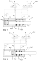
Figure 8 discloses an example structure of ahydraulic cylinder 10 of agripper 9. Thegripper 9 is provided with three different protruding length positions Lp1 for apiston rod 11 movable by means of apiston 15. Magnitude of the protruding length of thepiston rod 11 defines position of a gripping jaw, which is not shown. Thepiston rod 11 may have a fully retracted position (left, Lp1), a partly extended intermediate position (right, Lp3) and a fully extended position (middle, Lp2) which positions define operational modes M1 - M3 of thegripper 9. There is anadjusting piston 16 for effecting to the movements of thepiston 15 and thepiston rod 11. At least the intermediate length position Lp3 on the right side is defined by means of theadjusting piston 16. The adjustingpiston 16 is a sleeve-like piece mounted movably on thepiston rod 11. Then the adjustingpiston 16 may be a kind of a floating piston which can slide on thepiston rod 11 and move towards to its two extreme control positions. The adjustingpiston 16 has afirst face surface 17 facing towards thepiston 15 and being provided with a ring shapedaxial protrusion 18 facing towards thepiston 15. Diameter ofaxial protrusion 18 is minor than outer diameter of theadjusting piston 16 whereby theaxial protrusion 18 is able to serve as an axial stoppage surface for thepiston 15 when theadjusting piston 16 is moved to its extreme position towards thepiston 15. Further, thehydraulic cylinder 10 comprises three working pressure spaces Wp1, Wp2 and Wp3 wherein prevailing pressure is adjustable for moving thepiston 15 and for moving relative position of thepiston 15 and theadjusting piston 16. The first working pressure space Wp1 is on the piston side, the second working pressure space Wp2 is located between thepiston 15 and theadjusting piston 16, and the third working pressure space Wp3 is located on an opposite side of the adjusting piston compared to the second working pressure space Wp2. The working pressure spaces Wp1 - Wp3 are connected to one or morepressure fluid lines - As can be noted in
Figure 8 , thepiston 11 is in the length position Lp1 moved to its upmost extreme position, and in the length position Lp2 thepiston 15 is moved to its lowermost extreme position against the adjustingpiston 16 which is also at its lowermost extreme position. In the length position Lp3 the adjustingpiston 16 is moved to its upmost extreme position and thepiston 15 is set against theaxial protrusion 18 so that the intermediate position is achieved.Figure 8 clearly discloses that the adjustingpiston 16 moves between its extreme axial positions against fixed surfaces of abody 22 without any intermediate positions. -
Figures 9 - 12 discloses a structure of ahydraulic piston 10 and a hydraulic circuit for operating it and providing different length positions Lp1 - Lp3 for apiston rod 11. The hydraulic circuit may comprise two control valves, a first control valve Cv1 and a second control valve Cv2 by means of which pressure fluid is fed and discharged to and from working pressure space Wp1 - Wp3 for moving apiston 15 and anadjusting piston 16 to desired positions. The control valves Cv1 and Cv2 are connected to pressurefluid lines - In
Figure 9 the first control valve Cv1 connects a first working pressure space Wp1 to a tank T whereby thepiston 15 can move to its left most position since the second control valve Cv2 directs pressure fluid to the second working pressure space Wp2. Fluid flow from the third working pressure space Wp3 to tank T is prevented. Then thepiston rod 11 is retracted and has its shortest possible position. InFigure 9 a first movement direction is marked as A and an opposite second movement direction is marked as B. - In
Figure 10 thepiston rod 11 has its intermediate position wherein theadjusting piston 16 limits movement of thepiston 15 to the right. The second control valve Cv2 has changed its position and directs pressure fluid flow to the third working pressure space Wp3 and connects the second working pressure space Wp2 to the tank T. - In
Figure 11 thepiston rod 11 is in the same length position Lp1 as inFigure 9 but is free to move in either of its movement directions since the second control valve Cv2 is moved to its central position. All the working pressure space Wp1 - Wp3 are connected to the tank T by means of the control valves Cv1 and Cv2. - In
Figure 12 thepiston rod 11 is fully ejected and has its longest possible position. The adjustingpiston 16 has moved to its right most position since the third working pressure space Wp3 is connected to the tank T by means of the second control valve Cv2. The second working pressure space Wp2 is connected to the tank T by means of the first control valve Cv1. The first control valve Cv1 has changed its position and directs pressure fluid flow to the first working pressure space Wp1 whereby thepiston 15 is moved towards its right most extreme position. - In
Figures 9 - 12 control pressure lines are shown in broken lines. -
Figure 13 discloses agripper 9 arranged in connection with arod handling apparatus 23. Theapparatus 23 may comprise amagazine 24 for storingseveral drill rods 7a. Themagazine 24 may be rotatably mounted or may comprise other means for indexing. There is also a movable arm ormanipulator 25 provided with thegripper 9. Themanipulator 25 can move thedrill rods 7a between themagazine 24 and drilling axis DA of arock drilling apparatus 6. Thegripper 9 is disclosed more detailed inFigure 14 wherein is showed that thegripper 9 may comprise one movablegripping jaw 12a and one immovablegripping jaw 12b, which may be structural part of themanipulator 25 or may be separate part mounted to themanipulator 25. Ahydraulic cylinder 10 for moving the movablegripping jaw 12a is in accordance with the features and embodiments disclosed in this document and may be configured to provide thegripper 9 with the gripping mode, guiding mode and the open mode. - It may also be possible to use the same kind of
apparatus 23 for handling other drilling tools, such as drill bits. - The drawings and the related description are only intended to illustrate the idea of the invention. In its details, the invention may vary within the scope of the claims.
Claims (13)
- A gripper (9) for handling rock drilling tools (7),
wherein the gripper (9) comprises:at least one hydraulic cylinder (10) comprising a body (11, a piston (15), a piston rod (11) connected to the piston (15), working pressure spaces (WP), and several pressure fluid channels (19, 20, 21) connected to the working pressure spaces for feeding and discharging pressurized hydraulic fluid for moving the piston (15) in a first movement direction (A) and in an opposite second movement direction (B) ;at least one gripping jaw (12) movable by means of the hydraulic cylinder (10) towards and away from the drilling tool (7) arranged to pass through the gripper (9);characterized in that,the hydraulic cylinder (10) comprises at least one adjusting piston (16) having a first operating position with a first fixed stoppage and a second operating position with a fixed second stoppage;and wherein the adjusting piston (16) is configured to limit movement length of the piston rod (11) at one of the first and second operating positions to provide the at least one gripping jaw (12) an intermediate position between extreme movement positions of the at least one gripping jaw (12) . - The gripper as claimed in claim 1, characterized in that
the gripper (9) is provided with three operational modes (M1 - M3) wherein each mode has different protruding length (Lp1 - Lp3) for the piston rod (11) and wherein magnitude of the protruding length (Lp) of the piston rod (11) is configured to define position of the at least one gripping jaw (12) in relation to the rock drilling tool (7) being handled. - The gripper as claimed in claim 2, characterized in thatthe gripper (9) has an open mode (M1), a guiding mode (M3), and a gripping mode (M2);the piston rod (11) is configured to be moved to an extreme first protruding length in response to selection of the open mode (M1), and to an opposite extreme second protruding length in response selection of the gripping mode (M2) ;and wherein the piston rod (11) is configured to be moved to an intermediate position between the extreme first and second protruding lengths in response to selection of the guiding mode (M3).
- The gripper as claimed in any one of the preceding claims 1 to 3, characterized in that
the gripper (9) has an idle mode wherein all pressure spaces (Wp) of the hydraulic cylinder (10) are connected to at least one tank pressure line. - The gripper as claimed in any one of the preceding claims 1 to 4, characterized in that
the adjusting piston (16) is a sleeve-like piece mounted movably on the piston rod (11). - The gripper as claimed in any one of the preceding claims 1 to 5, characterized in that
the adjusting piston (16) has a first face surface (17) facing towards the piston (15) and being provided with a ring shaped axial protrusion (18) facing towards the piston (15) and diameter of which is minor than outer diameter of the adjusting piston (16) whereby the axial protrusion (18) is configured to serve as an axial stoppage surface for the piston (15) when the adjusting piston (16) is moved to its extreme position towards the piston (15). - The gripper as claimed in any one of the preceding claims 1 to 6, characterized in that
the hydraulic cylinder (10) comprises three working pressure spaces (Wp1 - Wp3) wherein prevailing pressure is adjustable for moving the piston (15) and for moving relative position of piston (15) and the adjusting piston (16). - The gripper as claimed in any one of the preceding claims 1 to 7, characterized in thatthe gripper (9) is part of a retainer (8) comprising two hydraulic cylinders (10a, 10b) mounted on opposite sides in relation to the drilling tool (7) arranged to pass through the retainer (8);piston rods (11a, 11b) of the hydraulic cylinders (10a, 10b) are facing towards each other; andthe retainer (8) comprises two gripping jaws (12a, 12b) which are mounted to distal ends of the piston rods (11a, 11b).
- The gripper as claimed in any one of the preceding claims 1 to 6, characterized in that
the gripper (9) is part of a retainer (8) comprising an articulated lever mechanism configured to transmit the movements of the hydraulic cylinder (10) to the gripping jaws (12a, 12b) mounted to lever arms (13a, 13b) of the lever mechanism. - The gripper as claimed in any one of the preceding claims 1 to 7, characterized in that
the gripper (9) is part of a rod handler (23) for moving the rock drilling tools (7) to drilling axis (DA) and comprising one movable gripping jaw (12a) movable in relation to a fixed counterpart (12b). - A rock drilling unit (4) for drilling holes to rock surfaces,
wherein the rock drilling unit (4) comprises:a feed beam (5);a rock drilling machine (6) mounted movably on the feed beam (5); anda retainer (8) at a front end portion of the feed beam (5) and being capable to selectively grip to a drilling tool (7) mountable to the rock drilling machine (6);characterized in that,the retainer (8) is provided with a gripper (9) which is in accordance with any one of the preceding claims 1 - 9. - A rock drilling unit (4) for drilling holes to rock surfaces,
wherein the rock drilling unit (4) comprises:a feed beam (5);a rock drilling machine (6) mounted movably on the feed beam (5); anda rod handler (23) for moving drilling tools (7) between a tool magazine (24) and drilling axis (DA);and wherein the rod handler (23) is provided with a gripper (9) being capable to selectively grip to the drilling tools (7) mountable to the rock drilling machine (6);characterized in that,the gripper (9) of the rod handler (23) is in accordance with any one of the preceding claims 1-7 and 10. - A method of handling a drilling tool (7) on a rock drilling unit (4);
wherein the method comprises:drilling a drill hole to the rock surface by means of the rock drilling unit (4);gripping the drilling tool (7) by means of at least one gripping jaw (12) of a gripper (9) mounted on the drilling unit (4); andmoving the at least one gripping jaw (12) in relation to the drilling tool (7) by means of at least one hydraulic cylinder (10) of the gripper (9);characterized byusing the gripper (9) as claimed in any one the previous claims 1 - 12 and providing the gripper (9) with at least three operational modes (M1 - M3) with different relative positions of the at least one gripping jaw (12).
Priority Applications (9)
| Application Number | Priority Date | Filing Date | Title |
|---|---|---|---|
| EP23172251.3A EP4461920B1 (en) | 2023-05-09 | 2023-05-09 | Gripper, rock drilling unit and method |
| CA3234603A CA3234603A1 (en) | 2023-05-09 | 2024-04-08 | Gripper, rock drilling unit and method |
| AU2024202576A AU2024202576A1 (en) | 2023-05-09 | 2024-04-19 | Gripper, rock drilling unit and method |
| CN202410495994.2A CN118933602A (en) | 2023-05-09 | 2024-04-24 | Holder, rock drilling unit and method |
| PE2024000987A PE20250044A1 (en) | 2023-05-09 | 2024-04-30 | CLAMP, ROCK DRILLING UNIT AND METHOD |
| JP2024075525A JP2024163983A (en) | 2023-05-09 | 2024-05-07 | Grip tool, rock drilling unit and method |
| CL2024001378A CL2024001378A1 (en) | 2023-05-09 | 2024-05-07 | Clamp, rock drilling unit and method. |
| US18/656,627 US20240376781A1 (en) | 2023-05-09 | 2024-05-07 | Gripper, rock drilling unit and method |
| MX2024005625A MX2024005625A (en) | 2023-05-09 | 2024-05-08 | Clamp, rock drilling unit, and method. |
Applications Claiming Priority (1)
| Application Number | Priority Date | Filing Date | Title |
|---|---|---|---|
| EP23172251.3A EP4461920B1 (en) | 2023-05-09 | 2023-05-09 | Gripper, rock drilling unit and method |
Publications (3)
| Publication Number | Publication Date |
|---|---|
| EP4461920A1 true EP4461920A1 (en) | 2024-11-13 |
| EP4461920C0 EP4461920C0 (en) | 2025-09-17 |
| EP4461920B1 EP4461920B1 (en) | 2025-09-17 |
Family
ID=86330810
Family Applications (1)
| Application Number | Title | Priority Date | Filing Date |
|---|---|---|---|
| EP23172251.3A Active EP4461920B1 (en) | 2023-05-09 | 2023-05-09 | Gripper, rock drilling unit and method |
Country Status (9)
| Country | Link |
|---|---|
| US (1) | US20240376781A1 (en) |
| EP (1) | EP4461920B1 (en) |
| JP (1) | JP2024163983A (en) |
| CN (1) | CN118933602A (en) |
| AU (1) | AU2024202576A1 (en) |
| CA (1) | CA3234603A1 (en) |
| CL (1) | CL2024001378A1 (en) |
| MX (1) | MX2024005625A (en) |
| PE (1) | PE20250044A1 (en) |
Families Citing this family (1)
| Publication number | Priority date | Publication date | Assignee | Title |
|---|---|---|---|---|
| CN119844462A (en) * | 2025-01-22 | 2025-04-18 | 广东南曦液压机械有限公司 | Pile turning oil cylinder, ocean engineering equipment and pile turning method |
Citations (5)
| Publication number | Priority date | Publication date | Assignee | Title |
|---|---|---|---|---|
| CA835784A (en) * | 1970-03-03 | Gardner-Denver Company | Centralizer | |
| WO2006059153A1 (en) * | 2004-11-30 | 2006-06-08 | Varco I/P, Inc. | Top drive unit, pipe gripping device and method of drilling a wellbore |
| WO2010092237A1 (en) * | 2009-02-12 | 2010-08-19 | Sandvik Mining And Construction Oy | Method for using retainer, and retainer |
| WO2012110704A1 (en) * | 2011-02-18 | 2012-08-23 | Sandvik Mining And Construction Oy | Control equipment for controlling drill rod |
| AU2012101626A4 (en) * | 2011-11-01 | 2012-12-06 | Sandvik Mining And Construction Oy | Guide for drilling tool, and drilling unit |
Family Cites Families (6)
| Publication number | Priority date | Publication date | Assignee | Title |
|---|---|---|---|---|
| FR1395635A (en) * | 1964-01-27 | 1965-04-16 | Nord Aviation | Three stable position fluid pressure cylinder |
| US4205594A (en) * | 1977-08-08 | 1980-06-03 | Burke Martin F | Fluid operated apparatus |
| US5012725A (en) * | 1990-04-19 | 1991-05-07 | Rockwell International Corporation | Three position actuator for shifting a two speed transfer case |
| FI121483B (en) * | 2009-02-12 | 2010-11-30 | Sandvik Mining & Constr Oy | Method for handling rod-shaped bodies, intermediate guide and rock drilling unit |
| EP2725183B1 (en) * | 2012-10-24 | 2020-03-25 | Sandvik Mining and Construction Oy | Mining vehicle and method of moving boom |
| SE538718C2 (en) * | 2013-08-02 | 2016-10-25 | Atlas Copco Rock Drills Ab | Device for handling drill string components at a rock drill rig and rock drill rig |
-
2023
- 2023-05-09 EP EP23172251.3A patent/EP4461920B1/en active Active
-
2024
- 2024-04-08 CA CA3234603A patent/CA3234603A1/en active Pending
- 2024-04-19 AU AU2024202576A patent/AU2024202576A1/en active Pending
- 2024-04-24 CN CN202410495994.2A patent/CN118933602A/en active Pending
- 2024-04-30 PE PE2024000987A patent/PE20250044A1/en unknown
- 2024-05-07 US US18/656,627 patent/US20240376781A1/en active Pending
- 2024-05-07 CL CL2024001378A patent/CL2024001378A1/en unknown
- 2024-05-07 JP JP2024075525A patent/JP2024163983A/en active Pending
- 2024-05-08 MX MX2024005625A patent/MX2024005625A/en unknown
Patent Citations (5)
| Publication number | Priority date | Publication date | Assignee | Title |
|---|---|---|---|---|
| CA835784A (en) * | 1970-03-03 | Gardner-Denver Company | Centralizer | |
| WO2006059153A1 (en) * | 2004-11-30 | 2006-06-08 | Varco I/P, Inc. | Top drive unit, pipe gripping device and method of drilling a wellbore |
| WO2010092237A1 (en) * | 2009-02-12 | 2010-08-19 | Sandvik Mining And Construction Oy | Method for using retainer, and retainer |
| WO2012110704A1 (en) * | 2011-02-18 | 2012-08-23 | Sandvik Mining And Construction Oy | Control equipment for controlling drill rod |
| AU2012101626A4 (en) * | 2011-11-01 | 2012-12-06 | Sandvik Mining And Construction Oy | Guide for drilling tool, and drilling unit |
Also Published As
| Publication number | Publication date |
|---|---|
| PE20250044A1 (en) | 2025-01-10 |
| MX2024005625A (en) | 2024-12-06 |
| AU2024202576A1 (en) | 2024-11-28 |
| US20240376781A1 (en) | 2024-11-14 |
| CN118933602A (en) | 2024-11-12 |
| CA3234603A1 (en) | 2025-10-30 |
| EP4461920C0 (en) | 2025-09-17 |
| EP4461920B1 (en) | 2025-09-17 |
| JP2024163983A (en) | 2024-11-26 |
| CL2024001378A1 (en) | 2024-10-11 |
Similar Documents
| Publication | Publication Date | Title |
|---|---|---|
| CA2722260C (en) | Rock-drilling unit, drill bit changer, and method for changing drill bit | |
| US10294738B2 (en) | Drill rod changer, rock drilling unit and method of changing drill rods | |
| FI110805B (en) | Arrangements for replacing a drilling component in a rock drilling device | |
| EP2396497B1 (en) | Method for using retainer, and retainer | |
| EP4461920B1 (en) | Gripper, rock drilling unit and method | |
| EP2396496B1 (en) | Method for manipulating rodlike pieces, centralizer and rock drilling unit | |
| US20030155140A1 (en) | Method of opening joints between drilling components, and rock drill | |
| US9903655B2 (en) | Impact tool for a hammer device and method for opening a tapping opening | |
| JP5644448B2 (en) | Chuck device | |
| EP4379182B1 (en) | Bolting head, bolting rig and method | |
| EP0533716B1 (en) | Apparatus for feeding a drilling machine in extension rod drilling | |
| JP4870694B2 (en) | Rod changer for drilling machine | |
| JP5090326B2 (en) | Rock bolt driving device | |
| EP4596831A1 (en) | Indexing head, bolting unit and method | |
| GB2122237A (en) | Drill rod guide | |
| AU2007241585B2 (en) | Rock drilling device | |
| JP2005127077A (en) | Press-in pile driver | |
| NO974784L (en) | Hydraulic device for turning the actuator to a rock drilling machine | |
| SE529824C2 (en) |
Legal Events
| Date | Code | Title | Description |
|---|---|---|---|
| PUAI | Public reference made under article 153(3) epc to a published international application that has entered the european phase |
Free format text: ORIGINAL CODE: 0009012 |
|
| STAA | Information on the status of an ep patent application or granted ep patent |
Free format text: STATUS: THE APPLICATION HAS BEEN PUBLISHED |
|
| AK | Designated contracting states |
Kind code of ref document: A1 Designated state(s): AL AT BE BG CH CY CZ DE DK EE ES FI FR GB GR HR HU IE IS IT LI LT LU LV MC ME MK MT NL NO PL PT RO RS SE SI SK SM TR |
|
| STAA | Information on the status of an ep patent application or granted ep patent |
Free format text: STATUS: REQUEST FOR EXAMINATION WAS MADE |
|
| 17P | Request for examination filed |
Effective date: 20250513 |
|
| GRAP | Despatch of communication of intention to grant a patent |
Free format text: ORIGINAL CODE: EPIDOSNIGR1 |
|
| STAA | Information on the status of an ep patent application or granted ep patent |
Free format text: STATUS: GRANT OF PATENT IS INTENDED |
|
| GRAS | Grant fee paid |
Free format text: ORIGINAL CODE: EPIDOSNIGR3 |
|
| RIC1 | Information provided on ipc code assigned before grant |
Ipc: E21B 7/02 20060101AFI20250606BHEP Ipc: E21B 19/14 20060101ALI20250606BHEP Ipc: E21B 19/24 20060101ALI20250606BHEP Ipc: E21B 19/16 20060101ALI20250606BHEP |
|
| INTG | Intention to grant announced |
Effective date: 20250624 |
|
| GRAA | (expected) grant |
Free format text: ORIGINAL CODE: 0009210 |
|
| STAA | Information on the status of an ep patent application or granted ep patent |
Free format text: STATUS: THE PATENT HAS BEEN GRANTED |
|
| AK | Designated contracting states |
Kind code of ref document: B1 Designated state(s): AL AT BE BG CH CY CZ DE DK EE ES FI FR GB GR HR HU IE IS IT LI LT LU LV MC ME MK MT NL NO PL PT RO RS SE SI SK SM TR |
|
| REG | Reference to a national code |
Ref country code: GB Ref legal event code: FG4D |
|
| REG | Reference to a national code |
Ref country code: CH Ref legal event code: EP |
|
| REG | Reference to a national code |
Ref country code: IE Ref legal event code: FG4D |
|
| REG | Reference to a national code |
Ref country code: DE Ref legal event code: R096 Ref document number: 602023006689 Country of ref document: DE |
|
| U01 | Request for unitary effect filed |
Effective date: 20250917 |
|
| U07 | Unitary effect registered |
Designated state(s): AT BE BG DE DK EE FI FR IT LT LU LV MT NL PT RO SE SI Effective date: 20250924 |
|
| PG25 | Lapsed in a contracting state [announced via postgrant information from national office to epo] |
Ref country code: HR Free format text: LAPSE BECAUSE OF FAILURE TO SUBMIT A TRANSLATION OF THE DESCRIPTION OR TO PAY THE FEE WITHIN THE PRESCRIBED TIME-LIMIT Effective date: 20250917 |
|
| PG25 | Lapsed in a contracting state [announced via postgrant information from national office to epo] |
Ref country code: GR Free format text: LAPSE BECAUSE OF FAILURE TO SUBMIT A TRANSLATION OF THE DESCRIPTION OR TO PAY THE FEE WITHIN THE PRESCRIBED TIME-LIMIT Effective date: 20251218 |
|
| PG25 | Lapsed in a contracting state [announced via postgrant information from national office to epo] |
Ref country code: RS Free format text: LAPSE BECAUSE OF FAILURE TO SUBMIT A TRANSLATION OF THE DESCRIPTION OR TO PAY THE FEE WITHIN THE PRESCRIBED TIME-LIMIT Effective date: 20251217 |
|
| PG25 | Lapsed in a contracting state [announced via postgrant information from national office to epo] |
Ref country code: SM Free format text: LAPSE BECAUSE OF FAILURE TO SUBMIT A TRANSLATION OF THE DESCRIPTION OR TO PAY THE FEE WITHIN THE PRESCRIBED TIME-LIMIT Effective date: 20250917 |
|
| PG25 | Lapsed in a contracting state [announced via postgrant information from national office to epo] |
Ref country code: ES Free format text: LAPSE BECAUSE OF FAILURE TO SUBMIT A TRANSLATION OF THE DESCRIPTION OR TO PAY THE FEE WITHIN THE PRESCRIBED TIME-LIMIT Effective date: 20250917 |
|
| PG25 | Lapsed in a contracting state [announced via postgrant information from national office to epo] |
Ref country code: IS Free format text: LAPSE BECAUSE OF FAILURE TO SUBMIT A TRANSLATION OF THE DESCRIPTION OR TO PAY THE FEE WITHIN THE PRESCRIBED TIME-LIMIT Effective date: 20260117 |
|
| PG25 | Lapsed in a contracting state [announced via postgrant information from national office to epo] |
Ref country code: CZ Free format text: LAPSE BECAUSE OF FAILURE TO SUBMIT A TRANSLATION OF THE DESCRIPTION OR TO PAY THE FEE WITHIN THE PRESCRIBED TIME-LIMIT Effective date: 20250917 |
|
| PG25 | Lapsed in a contracting state [announced via postgrant information from national office to epo] |
Ref country code: PL Free format text: LAPSE BECAUSE OF FAILURE TO SUBMIT A TRANSLATION OF THE DESCRIPTION OR TO PAY THE FEE WITHIN THE PRESCRIBED TIME-LIMIT Effective date: 20250917 |
|
| PG25 | Lapsed in a contracting state [announced via postgrant information from national office to epo] |
Ref country code: SK Free format text: LAPSE BECAUSE OF FAILURE TO SUBMIT A TRANSLATION OF THE DESCRIPTION OR TO PAY THE FEE WITHIN THE PRESCRIBED TIME-LIMIT Effective date: 20250917 |
|
| U20 | Renewal fee for the european patent with unitary effect paid |
Year of fee payment: 4 Effective date: 20260601 |
|
| PGFP | Annual fee paid to national office [announced via postgrant information from national office to epo] |
Ref country code: NO Payment date: 20260512 Year of fee payment: 4 |
|
| PGFP | Annual fee paid to national office [announced via postgrant information from national office to epo] |
Ref country code: TR Payment date: 20260506 Year of fee payment: 4 |
|
| PLBE | No opposition filed within time limit |
Free format text: ORIGINAL CODE: 0009261 |
|
| STAA | Information on the status of an ep patent application or granted ep patent |
Free format text: STATUS: NO OPPOSITION FILED WITHIN TIME LIMIT |
|
| REG | Reference to a national code |
Ref country code: CH Ref legal event code: L10 Free format text: ST27 STATUS EVENT CODE: U-0-0-L10-L00 (AS PROVIDED BY THE NATIONAL OFFICE) Effective date: 20260729 |