EP4461916A1 - Energy storage cabin - Google Patents
Energy storage cabin Download PDFInfo
- Publication number
- EP4461916A1 EP4461916A1 EP24174653.6A EP24174653A EP4461916A1 EP 4461916 A1 EP4461916 A1 EP 4461916A1 EP 24174653 A EP24174653 A EP 24174653A EP 4461916 A1 EP4461916 A1 EP 4461916A1
- Authority
- EP
- European Patent Office
- Prior art keywords
- door panel
- cabin
- inner door
- energy storage
- outer door
- Prior art date
- Legal status (The legal status is an assumption and is not a legal conclusion. Google has not performed a legal analysis and makes no representation as to the accuracy of the status listed.)
- Granted
Links
Images




Classifications
-
- E—FIXED CONSTRUCTIONS
- E06—DOORS, WINDOWS, SHUTTERS, OR ROLLER BLINDS IN GENERAL; LADDERS
- E06B—FIXED OR MOVABLE CLOSURES FOR OPENINGS IN BUILDINGS, VEHICLES, FENCES OR LIKE ENCLOSURES IN GENERAL, e.g. DOORS, WINDOWS, BLINDS, GATES
- E06B5/00—Doors, windows, or like closures for special purposes; Border constructions therefor
-
- E—FIXED CONSTRUCTIONS
- E06—DOORS, WINDOWS, SHUTTERS, OR ROLLER BLINDS IN GENERAL; LADDERS
- E06B—FIXED OR MOVABLE CLOSURES FOR OPENINGS IN BUILDINGS, VEHICLES, FENCES OR LIKE ENCLOSURES IN GENERAL, e.g. DOORS, WINDOWS, BLINDS, GATES
- E06B3/00—Window sashes, door leaves, or like elements for closing wall or like openings; Layout of fixed or moving closures, e.g. windows in wall or like openings; Features of rigidly-mounted outer frames relating to the mounting of wing frames
- E06B3/70—Door leaves
- E06B3/7015—Door leaves characterised by the filling between two external panels
-
- E—FIXED CONSTRUCTIONS
- E04—BUILDING
- E04H—BUILDINGS OR LIKE STRUCTURES FOR PARTICULAR PURPOSES; SWIMMING OR SPLASH BATHS OR POOLS; MASTS; FENCING; TENTS OR CANOPIES, IN GENERAL
- E04H5/00—Buildings or groups of buildings for industrial or agricultural purposes
- E04H5/02—Buildings or groups of buildings for industrial purposes, e.g. for power-plants or factories
-
- E—FIXED CONSTRUCTIONS
- E06—DOORS, WINDOWS, SHUTTERS, OR ROLLER BLINDS IN GENERAL; LADDERS
- E06B—FIXED OR MOVABLE CLOSURES FOR OPENINGS IN BUILDINGS, VEHICLES, FENCES OR LIKE ENCLOSURES IN GENERAL, e.g. DOORS, WINDOWS, BLINDS, GATES
- E06B3/00—Window sashes, door leaves, or like elements for closing wall or like openings; Layout of fixed or moving closures, e.g. windows in wall or like openings; Features of rigidly-mounted outer frames relating to the mounting of wing frames
- E06B3/70—Door leaves
- E06B3/82—Flush doors, i.e. with completely flat surface
- E06B3/822—Flush doors, i.e. with completely flat surface with an internal foursided frame
-
- E—FIXED CONSTRUCTIONS
- E06—DOORS, WINDOWS, SHUTTERS, OR ROLLER BLINDS IN GENERAL; LADDERS
- E06B—FIXED OR MOVABLE CLOSURES FOR OPENINGS IN BUILDINGS, VEHICLES, FENCES OR LIKE ENCLOSURES IN GENERAL, e.g. DOORS, WINDOWS, BLINDS, GATES
- E06B5/00—Doors, windows, or like closures for special purposes; Border constructions therefor
- E06B5/10—Doors, windows, or like closures for special purposes; Border constructions therefor for protection against air-raid or other war-like action; for other protective purposes
- E06B5/16—Fireproof doors or similar closures; Adaptations of fixed constructions therefor
- E06B5/164—Sealing arrangements between the door or window and its frame, e.g. intumescent seals specially adapted therefor
-
- E—FIXED CONSTRUCTIONS
- E06—DOORS, WINDOWS, SHUTTERS, OR ROLLER BLINDS IN GENERAL; LADDERS
- E06B—FIXED OR MOVABLE CLOSURES FOR OPENINGS IN BUILDINGS, VEHICLES, FENCES OR LIKE ENCLOSURES IN GENERAL, e.g. DOORS, WINDOWS, BLINDS, GATES
- E06B3/00—Window sashes, door leaves, or like elements for closing wall or like openings; Layout of fixed or moving closures, e.g. windows in wall or like openings; Features of rigidly-mounted outer frames relating to the mounting of wing frames
- E06B3/70—Door leaves
- E06B3/7015—Door leaves characterised by the filling between two external panels
- E06B2003/7032—Door leaves characterised by the filling between two external panels of non-vegetal fibrous material, e.g. glass or rock wool
-
- E—FIXED CONSTRUCTIONS
- E06—DOORS, WINDOWS, SHUTTERS, OR ROLLER BLINDS IN GENERAL; LADDERS
- E06B—FIXED OR MOVABLE CLOSURES FOR OPENINGS IN BUILDINGS, VEHICLES, FENCES OR LIKE ENCLOSURES IN GENERAL, e.g. DOORS, WINDOWS, BLINDS, GATES
- E06B3/00—Window sashes, door leaves, or like elements for closing wall or like openings; Layout of fixed or moving closures, e.g. windows in wall or like openings; Features of rigidly-mounted outer frames relating to the mounting of wing frames
- E06B3/70—Door leaves
- E06B2003/7049—Specific panel characteristics
- E06B2003/7051—Specific panel characteristics of layered construction involving different materials
-
- E—FIXED CONSTRUCTIONS
- E06—DOORS, WINDOWS, SHUTTERS, OR ROLLER BLINDS IN GENERAL; LADDERS
- E06B—FIXED OR MOVABLE CLOSURES FOR OPENINGS IN BUILDINGS, VEHICLES, FENCES OR LIKE ENCLOSURES IN GENERAL, e.g. DOORS, WINDOWS, BLINDS, GATES
- E06B3/00—Window sashes, door leaves, or like elements for closing wall or like openings; Layout of fixed or moving closures, e.g. windows in wall or like openings; Features of rigidly-mounted outer frames relating to the mounting of wing frames
- E06B3/70—Door leaves
- E06B2003/7059—Specific frame characteristics
- E06B2003/7074—Metal frames
- E06B2003/7076—Metal frames insulated
-
- Y—GENERAL TAGGING OF NEW TECHNOLOGICAL DEVELOPMENTS; GENERAL TAGGING OF CROSS-SECTIONAL TECHNOLOGIES SPANNING OVER SEVERAL SECTIONS OF THE IPC; TECHNICAL SUBJECTS COVERED BY FORMER USPC CROSS-REFERENCE ART COLLECTIONS [XRACs] AND DIGESTS
- Y02—TECHNOLOGIES OR APPLICATIONS FOR MITIGATION OR ADAPTATION AGAINST CLIMATE CHANGE
- Y02E—REDUCTION OF GREENHOUSE GAS [GHG] EMISSIONS, RELATED TO ENERGY GENERATION, TRANSMISSION OR DISTRIBUTION
- Y02E60/00—Enabling technologies; Technologies with a potential or indirect contribution to GHG emissions mitigation
- Y02E60/10—Energy storage using batteries
Definitions
- the present disclosure relates to the field of energy storage technologies, and more particularly, to an energy storage cabin.
- An energy storage cabin is mainly used to store an energy storage element such as a battery and can also have a temperature control system and a heat dissipation system therein.
- the battery generates a large amount of heat during charging and discharging.
- the temperature control system and the heat dissipation system are used to control a temperature in the energy storage cabin, such that a temperature of an environment where the battery is located falls within a predetermined temperature range. However, during an actual operation, the temperature in the energy storage cabin can be uncontrollable.
- an energy storage cabin is provided.
- a cabin door has a relatively low thermal conductivity. Therefore, a quantity of heat/refrigeration in a first accommodation space can be stored for a long time, and a probability that a quantity of heat/refrigeration outside the energy storage cabin is transferred to the first accommodation space through the cabin door is greatly reduced, such that a temperature in the energy storage cabin can be accurately controlled.
- An energy storage cabin includes: a cabin body having at least one opening and a first accommodation space for accommodating an energy storage element; and at least one cabin door each disposed at each of the at least one opening of the cabin body in an openable and closable manner.
- Each of the at least one cabin door includes an inner door panel, an outer door panel, and a plurality of connecting members for connecting the inner door panel with the outer door panel.
- the inner door panel is located at a side of the outer door panel facing towards the first accommodation space.
- a thermal insulation layer is provided between the inner door panel and the outer door panel.
- a heat insulation pad is sandwiched between the inner door panel and the outer door panel at each of the plurality of connecting members.
- the above solution provides the energy storage cabin.
- the cabin door includes the inner door panel and the outer door panel.
- the thermal insulation layer is provided between the inner door panel and the outer door panel.
- the heat insulation pad is sandwiched at a position where the inner door panel and the outer door panel are connected by the connecting member.
- the inner door panel is in no direct contact with the outer door panel, which allows the cabin door as a whole to have a relatively low thermal conductivity. Therefore, the quantity of heat/refrigeration in the first accommodation space can be stored for a long time, and the probability that a quantity of heat/refrigeration outside the energy storage cabin is transferred to the first accommodation space through the cabin door is greatly reduced, such that the temperature in the energy storage cabin can be accurately controlled.
- a fixation frame is provided at the side of the outer door panel facing towards the first accommodation space.
- Each of the plurality of connecting members penetrates the inner door panel and the fixation frame in an arrangement direction from the inner door panel to the outer door panel to connect the inner door panel with the outer door panel.
- the heat insulation pad has an annular closed structure in a shape corresponding to a shape of the fixation frame.
- the heat insulation pad is sandwiched between the fixation frame and an outer periphery of the inner door panel.
- the fixation frame provides an elevation for an inner side surface of the outer door panel, such that a thickness of a distance between the inner door panel and the outer door panel meets a requirement of the thermal insulation layer.
- the overall thermal conductivity of the cabin door is greatly reduced when a thickness of the thermal insulation layer meets a thermal insulation and heat preservation requirement.
- the fixation frame includes two first supporting members that are opposite to each other in a length direction of the cabin door and two second supporting members that are opposite to each other in a width direction of the cabin door, the two first supporting members and the two second supporting members being connected end-to-end in sequence to form the fixation frame corresponding to the outer periphery of the inner door panel.
- Each of the two first supporting members and the two second supporting members includes a bottom wall and two side walls located between the bottom wall and the outer door panel.
- a second accommodation space is defined by the two side walls, the bottom wall, and the outer door panel.
- Each of the plurality of connecting members is connected to the inner door panel and the bottom wall, at least part of the connecting member being accommodated in the second accommodation space.
- the heat insulation pad is sandwiched between the bottom wall and the outer periphery of the inner door panel.
- a part of the connecting member that penetrates the fixation frame can be accommodated in a distance formed between the fixation frame and the outer door panel, to avoid traces of mounting of the connecting member outside the outer door panel.
- the fixation frame has a thickness of H1.
- a middle part of the inner door panel protrudes relative to the outer periphery of the inner door panel by a height of H2 in a direction facing away from the outer door panel.
- the heat insulation pad has a thickness of d.
- each of the plurality of connecting members is a fastener, the plurality of connecting members being evenly arranged at intervals in a peripheral direction of the fixation frame. The entire fixation frame is locked together with the inner door panel, and thus the fixation frame and the inner door panel are reliably connected to each other.
- a side surface of the inner door panel facing towards the outer door panel is provided with a plurality of reinforcing ribs arranged at intervals, each of the plurality of reinforcing ribs being located between the inner door panel and the outer door panel.
- the reinforcement ribs provided at the inner door panel effectively improve a strength of the cabin door.
- each of the plurality of reinforcing ribs is inserted into the thermal insulation layer, a length direction of each of the plurality of reinforcing ribs being consistent with a width direction of each corresponding cabin door of the at least one cabin door; and/or each of the plurality of reinforcing ribs includes a connection portion and an extension portion that are connected to each other to form a structure with an L-shaped cross section, the connection portion being connected to the inner door panel, and the extension portion protruding towards the outer door panel.
- the reinforcing ribs hidden in the thermal insulation layer not only improve the strength of the cabin door, but also avoid heat transfer through the reinforcing ribs.
- the thermal insulation layer is a rock wool board provided between the inner door panel and the outer door panel.
- Thermal insulation of rock wool enables a low efficiency of energy transfer between a space inside the energy storage cabin and a space outside the energy storage cabin, which in turn allows for accurate temperature control of the space inside the energy storage cabin.
- the outer door panel is hinged to the cabin body, and the at least one cabin door is openable and closable at the at least one opening of the cabin body.
- the cabin door is hingedly connected to the cabin body for easy opening and closing.
- the cabin body has a plurality of first accommodation spaces and a plurality of openings.
- Each of the plurality of first accommodation spaces corresponds to one of the plurality of openings.
- Each of the plurality of openings is provided with one cabin door.
- Each of the plurality of first accommodation spaces has a temperature control system provided therein and configured to control a temperature in the first accommodation space.
- the plurality of first accommodation spaces can hold energy storage elements such as batteries and provides a large storage space.
- an energy storage cabin 10 is provided.
- the energy storage cabin 10 includes a cabin body 11 and at least one cabin door 12.
- the cabin body 11 has a first accommodation space for accommodating an energy storage element.
- a battery and a temperature control system can be mounted in the first accommodation space.
- the cabin body 11 has at least one opening.
- the at least one cabin door 12 is disposed at the at least one opening of the cabin body 11 in an openable and closable manner.
- the cabin door 12 includes an inner door panel 122, an outer door panel 121, and a plurality of connecting members 127 for connecting the inner door panel 122 with the outer door panel 121.
- the inner door panel 122 is located at a side of the outer door panel 121 facing towards the first accommodation space.
- a thermal insulation layer 125 is provided between the inner door panel 122 and the outer door panel 121.
- a heat insulation pad 126 is sandwiched between the inner door panel 122 and the outer door panel 121 at each connecting member 127.
- the cabin door 12 includes the inner door panel 122 and the outer door panel 121.
- the thermal insulation layer 125 is provided between the inner door panel 122 and the outer door panel 121.
- the heat insulation pad 126 is sandwiched at a position where the inner door panel 122 and the outer door panel 121 are connected by the connecting member 127. In this way, the inner door panel 122 is in no direct contact with the outer door panel 121.
- a thermal conductivity of the thermal insulation layer 125 is smaller than a thermal conductivity of the inner door panel 122 and a thermal conductivity of the outer door panel 121.
- a thermal conductivity of the heat insulation pad 126 is smaller than the thermal conductivity of the inner door panel 122 and the thermal conductivity of the outer door panel 121. Since heat transfer between an inside of the cabin door 12 and an outside of the cabin door 12 needs to pass through the thermal insulation layer 125 or the heat insulation pad 126, the cabin door 12 as a whole has a relatively low thermal conductivity. Therefore, a quantity of heat/refrigeration in the first accommodation space can be stored for a long time, and a probability that a quantity of heat/refrigeration outside the energy storage cabin 10 is transferred to the first accommodation space through the cabin door 12 is greatly reduced, such that a temperature in the energy storage cabin 10 can be accurately controlled.
- the heat insulation pad 126 has an annular closed structure.
- the heat insulation pad 126 corresponding to an outer periphery of the inner door panel 122 is tightly pressed between the outer door panel 121 and an outer periphery of the inner door panel 122.
- the connecting member 127 penetrates the outer periphery of the inner door panel 122, the heat insulation pad 126, and the outer door panel 121 to connect the inner door panel 122, the heat insulation pad 126, and the outer door panel 121 together.
- the annular closed structure is a structure connected end-to-end and capable of forming a closed space, such as a frame structure formed in a polygonal shape and a circular element.
- a fixation frame 123 is provided at the side of the outer door panel 121 facing towards the first accommodation space.
- the connecting member 127 penetrates the inner door panel 122 and the fixation frame 123 in an arrangement direction from the inner door panel 122 to the outer door panel 121 to connect the inner door panel 122 with the outer door panel 121.
- the heat insulation pad 126 has an annular closed structure in a shape corresponding to a shape of the fixation frame 123.
- the heat insulation pad 125 is sandwiched between the fixation frame 123 and an outer periphery of the inner door panel 122.
- the fixation frame 123 provides an elevation, such that a thickness of a space between the inner door panel 122 and the outer door panel 121 meets a requirement of the thermal insulation layer 125.
- the overall thermal conductivity of the cabin door 12 is greatly reduced when a thickness of the thermal insulation layer 125 meets a thermal insulation and heat preservation requirement.
- the connecting member 127 can directly penetrate the inner door panel 122 and the outer door panel 121 to connect the inner door panel 122 and the outer door panel 121 together.
- the fixation frame 123 After the fixation frame 123 is provided at the side of the outer door panel 121 facing towards the first accommodation space, the inner door panel 122 and the outer door panel 121 are indirectly connected together through the fixation frame 123.
- the connecting member 127 and the outer door panel 121 have no need to be in direct contact.
- heat between the inner door panel 122 and the outer door panel 121 is kept from being transferred simply through the connecting member 127, further reducing a heat transfer efficiency.
- the fixation frame 123 includes two first supporting members 1231 that are opposite to each other in a length direction of the cabin door 12 and two second supporting members 1232 that are opposite to each other in a width direction of the cabin door 12.
- the two first supporting members 1231 and the two second supporting members 1232 are connected end-to-end in sequence to form the fixation frame 123 corresponding to the outer periphery of the inner door panel 122.
- each of the first supporting member 1231 and the second supporting member 1232 includes a bottom wall and two side walls. The two side walls are located between the bottom wall and the outer door panel.
- the two side walls, the bottom wall, and the outer door panel 121 enclose to form a second accommodation space 1233.
- the connecting member 127 is connected to the inner door panel 122 and the bottom wall. At least part of the connecting member 127 is accommodated in the second accommodation space 1233.
- the heat insulation pad 126 is sandwiched between the bottom wall and the outer periphery of the inner door panel 122.
- the connecting member 127 includes a screw.
- the screw is partially located in the second accommodation space 1233 when connecting the fixation frame 123 with the inner door panel 122.
- the fixation frame 123 can be welded to the outer door panel 121.
- two side walls of each of the first supporting member 1231 and the second supporting member 1232 can be welded to the outer door panel 121.
- a middle part of the inner door panel 122 protrudes relative to the outer periphery of the inner door panel 122 by a height of H2 in a direction away from the outer door panel 121. Therefore, a groove is formed at a side of the inner door panel 122 facing towards the outer door panel 121. The groove can accommodate the thermal insulation layer 125. When the inner door panel 122 is filled with the thermal insulation layer 125, the groove can define a region filled with the thermal insulation layer 125.
- the fixation frame 123 has a thickness of H1.
- the heat insulation pad 126 has a thickness of d.
- each of the plurality of connecting members 127 is a fastener, such as a screw, a rivet, an elastic fitting member, or the like.
- the plurality of fasteners is evenly arranged at intervals in a peripheral direction of the fixation frame 123. The entire fixation frame 123 is locked together with the inner door panel 122, and thus the fixation frame 123 and the inner door panel 122 are reliably connected to each other.
- a side surface of the inner door panel 122 facing towards the outer door panel 121 is provided with a plurality of reinforcing ribs 124 arranged at intervals.
- Each reinforcing rib 124 is located between the inner door panel 122 and the outer door panel 121.
- the reinforcing rib 124 can be welded to the inner door panel 122.
- the reinforcing rib 124 provided at an outer side surface of the inner door panel 122 effectively improve a strength of the cabin door 12.
- each reinforcing rib 124 is consistent with a width direction of the corresponding cabin door 12.
- the reinforcing rib 124 can be arranged in other directions, which is not limited in the present disclosure.
- each reinforcing rib 124 is inserted into the thermal insulation layer 125.
- the reinforcing rib 124 inserted into the thermal insulation layer 125 not only improves the strength of the cabin door 12, but also avoid heat conduction through the reinforcing rib 124.
- the reinforcing rib 124 includes a connection portion 1241 and an extension portion 1242 that are connected to each other to form a structure with an L-shaped cross section.
- the connection portion 1241 is connected to the inner door panel 122.
- the extension portion 1242 protrudes towards the outer door panel 121.
- the thermal insulation layer 125 is a rock wool board provided between the inner door panel 122 and the outer door panel 121. Thermal insulation properties of rock wool enables a low efficiency of energy transfer between a space inside the energy storage cabin 10 and a space outside the energy storage cabin 10, which in turn allows for accurate temperature control of the space inside the energy storage cabin 10.
- the outer door panel 121 is hinged to the cabin body 11, and the cabin door 12 is openable and closable at the opening of the cabin body 11.
- the cabin door 12 is hingedly connected to the cabin body 11 for easy opening and closing.
- a plurality of hinge positions can be formed at a longitudinally distributed sideline of the outer door panel 121, for allowing the outer door panel 121 to be hinged to the cabin body 11.
- the cabin body 11 has a plurality of first accommodation spaces and a plurality of openings.
- Each of the plurality of first accommodation spaces corresponds to one of the plurality of openings.
- Each of the plurality of openings is provided with one cabin door 12.
- the plurality of first accommodation spaces can hold energy storage elements such as batteries and provides a large storage space.
- Atemperature control system can be provided in the first accommodation space and configured to control a temperature in the first accommodation space.
- first and second are only used for descriptive purposes, and cannot be understood as indicating or implying relative importance or implicitly indicating the number of indicated technical features. Therefore, the features associated with “first” and “second” may explicitly or implicitly include at least one of the features. In the description of the present disclosure, “plurality” means at least two, unless otherwise specifically defined.
- the first feature "on” or “under” the second feature may mean that the first feature is in direct contact with the second feature, or the first and second features are in indirect contact through an intermediate.
- the first feature "above” the second feature may mean that the first feature is directly above or obliquely above the second feature, or simply mean that the level of the first feature is higher than that of the second feature.
- the first feature "below” the second feature may mean that the first feature is directly below or obliquely below the second feature, or simply mean that the level of the first feature is smaller than that of the second feature.
Landscapes
- Engineering & Computer Science (AREA)
- Civil Engineering (AREA)
- Structural Engineering (AREA)
- Architecture (AREA)
- Refrigerator Housings (AREA)
- Battery Mounting, Suspending (AREA)
- Body Structure For Vehicles (AREA)
Abstract
Description
- The present disclosure relates to the field of energy storage technologies, and more particularly, to an energy storage cabin.
- An energy storage cabin is mainly used to store an energy storage element such as a battery and can also have a temperature control system and a heat dissipation system therein. The battery generates a large amount of heat during charging and discharging. The temperature control system and the heat dissipation system are used to control a temperature in the energy storage cabin, such that a temperature of an environment where the battery is located falls within a predetermined temperature range. However, during an actual operation, the temperature in the energy storage cabin can be uncontrollable.
- In view of the above problems, an energy storage cabin is provided. A cabin door has a relatively low thermal conductivity. Therefore, a quantity of heat/refrigeration in a first accommodation space can be stored for a long time, and a probability that a quantity of heat/refrigeration outside the energy storage cabin is transferred to the first accommodation space through the cabin door is greatly reduced, such that a temperature in the energy storage cabin can be accurately controlled.
- An energy storage cabin includes: a cabin body having at least one opening and a first accommodation space for accommodating an energy storage element; and at least one cabin door each disposed at each of the at least one opening of the cabin body in an openable and closable manner. Each of the at least one cabin door includes an inner door panel, an outer door panel, and a plurality of connecting members for connecting the inner door panel with the outer door panel. The inner door panel is located at a side of the outer door panel facing towards the first accommodation space. A thermal insulation layer is provided between the inner door panel and the outer door panel. A heat insulation pad is sandwiched between the inner door panel and the outer door panel at each of the plurality of connecting members.
- The above solution provides the energy storage cabin. The cabin door includes the inner door panel and the outer door panel. The thermal insulation layer is provided between the inner door panel and the outer door panel. The heat insulation pad is sandwiched at a position where the inner door panel and the outer door panel are connected by the connecting member. In this way, the inner door panel is in no direct contact with the outer door panel, which allows the cabin door as a whole to have a relatively low thermal conductivity. Therefore, the quantity of heat/refrigeration in the first accommodation space can be stored for a long time, and the probability that a quantity of heat/refrigeration outside the energy storage cabin is transferred to the first accommodation space through the cabin door is greatly reduced, such that the temperature in the energy storage cabin can be accurately controlled.
- In an embodiment, a fixation frame is provided at the side of the outer door panel facing towards the first accommodation space. Each of the plurality of connecting members penetrates the inner door panel and the fixation frame in an arrangement direction from the inner door panel to the outer door panel to connect the inner door panel with the outer door panel. The heat insulation pad has an annular closed structure in a shape corresponding to a shape of the fixation frame. The heat insulation pad is sandwiched between the fixation frame and an outer periphery of the inner door panel. The fixation frame provides an elevation for an inner side surface of the outer door panel, such that a thickness of a distance between the inner door panel and the outer door panel meets a requirement of the thermal insulation layer. The overall thermal conductivity of the cabin door is greatly reduced when a thickness of the thermal insulation layer meets a thermal insulation and heat preservation requirement.
- In an embodiment, the fixation frame includes two first supporting members that are opposite to each other in a length direction of the cabin door and two second supporting members that are opposite to each other in a width direction of the cabin door, the two first supporting members and the two second supporting members being connected end-to-end in sequence to form the fixation frame corresponding to the outer periphery of the inner door panel. Each of the two first supporting members and the two second supporting members includes a bottom wall and two side walls located between the bottom wall and the outer door panel. A second accommodation space is defined by the two side walls, the bottom wall, and the outer door panel. Each of the plurality of connecting members is connected to the inner door panel and the bottom wall, at least part of the connecting member being accommodated in the second accommodation space. The heat insulation pad is sandwiched between the bottom wall and the outer periphery of the inner door panel. A part of the connecting member that penetrates the fixation frame can be accommodated in a distance formed between the fixation frame and the outer door panel, to avoid traces of mounting of the connecting member outside the outer door panel.
- In an embodiment, the fixation frame has a thickness of H1. A middle part of the inner door panel protrudes relative to the outer periphery of the inner door panel by a height of H2 in a direction facing away from the outer door panel. The heat insulation pad has a thickness of d. A distance H is formed between the middle part of the inner door panel and the outer door panel, where H=H1+H2+d. When the outer periphery of the inner door panel is connected to the fixation frame, a distance between the middle part of the inner door panel and the outer door panel is relatively large, and thus the thermal insulation layer between the inner door panel and the outer door panel has a heat preservation and thermal insulation capacity meeting a requirement of the energy storage cabin.
- In an embodiment, each of the plurality of connecting members is a fastener, the plurality of connecting members being evenly arranged at intervals in a peripheral direction of the fixation frame. The entire fixation frame is locked together with the inner door panel, and thus the fixation frame and the inner door panel are reliably connected to each other.
- In an embodiment, a side surface of the inner door panel facing towards the outer door panel is provided with a plurality of reinforcing ribs arranged at intervals, each of the plurality of reinforcing ribs being located between the inner door panel and the outer door panel. The reinforcement ribs provided at the inner door panel effectively improve a strength of the cabin door.
- In an embodiment, each of the plurality of reinforcing ribs is inserted into the thermal insulation layer, a length direction of each of the plurality of reinforcing ribs being consistent with a width direction of each corresponding cabin door of the at least one cabin door; and/or each of the plurality of reinforcing ribs includes a connection portion and an extension portion that are connected to each other to form a structure with an L-shaped cross section, the connection portion being connected to the inner door panel, and the extension portion protruding towards the outer door panel. The reinforcing ribs hidden in the thermal insulation layer not only improve the strength of the cabin door, but also avoid heat transfer through the reinforcing ribs.
- In an embodiment, the thermal insulation layer is a rock wool board provided between the inner door panel and the outer door panel. Thermal insulation of rock wool enables a low efficiency of energy transfer between a space inside the energy storage cabin and a space outside the energy storage cabin, which in turn allows for accurate temperature control of the space inside the energy storage cabin.
- In an embodiment, the outer door panel is hinged to the cabin body, and the at least one cabin door is openable and closable at the at least one opening of the cabin body. The cabin door is hingedly connected to the cabin body for easy opening and closing.
- In an embodiment, the cabin body has a plurality of first accommodation spaces and a plurality of openings. Each of the plurality of first accommodation spaces corresponds to one of the plurality of openings. Each of the plurality of openings is provided with one cabin door. Each of the plurality of first accommodation spaces has a temperature control system provided therein and configured to control a temperature in the first accommodation space. The plurality of first accommodation spaces can hold energy storage elements such as batteries and provides a large storage space.
-
-
FIG. 1 is a schematic view of a structure of an energy storage cabin according to an embodiment. -
FIG. 2 is an exploded view of a cabin door in the energy storage cabin illustrated inFIG. 1 . -
FIG. 3 is a front view of the cabin door illustrated inFIG. 2 . -
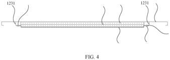
FIG. 4 is a cross-sectional view taken along line A-A inFIG. 3 . -
FIG. 5 is a cross-sectional view taken along line B-B inFIG. 3 . -
FIG. 6 is an enlarged partial view of part C inFIG. 5 . - Description of reference numerals of the accompanying drawings:
10, energy storage cabin; 11, cabin body; 12, cabin door; 121, outer door panel; 122, inner door panel; 123, fixation frame; 1231, first supporting member; 1232, second supporting member; 1233, second accommodation space; 124, reinforcing rib; 1241, connection portion; 1422, extension portion; 125, thermal insulation layer; 126, heat insulation pad; 127, connecting member. - In order to clarify and explain the above-mentioned objects, features, and advantages of the present disclosure, specific embodiments of the present disclosure are described in detail below in conjunction with the accompanying drawings. In the following description, many specific details are provided to facilitate full understanding of the present disclosure. However, the present disclosure can be implemented in various manners other than those described herein, and similar improvements can be made by those skilled in the art without contradicting the intent of the present disclosure. Therefore, the present disclosure is not limited by specific embodiments disclosed below.
- As illustrated in
FIG. 1 , in some embodiments of the present disclosure, anenergy storage cabin 10 is provided. Theenergy storage cabin 10 includes a cabin body 11 and at least onecabin door 12. The cabin body 11 has a first accommodation space for accommodating an energy storage element. For example, a battery and a temperature control system can be mounted in the first accommodation space. The cabin body 11 has at least one opening. The at least onecabin door 12 is disposed at the at least one opening of the cabin body 11 in an openable and closable manner. - As illustrated in
FIG. 2 to FIG. 5 , thecabin door 12 includes aninner door panel 122, anouter door panel 121, and a plurality of connecting members 127 for connecting theinner door panel 122 with theouter door panel 121. Theinner door panel 122 is located at a side of theouter door panel 121 facing towards the first accommodation space. A thermal insulation layer 125 is provided between theinner door panel 122 and theouter door panel 121. A heat insulation pad 126 is sandwiched between theinner door panel 122 and theouter door panel 121 at each connecting member 127. - In the
energy storage cabin 10 provided in the above solution, thecabin door 12 includes theinner door panel 122 and theouter door panel 121. Also, the thermal insulation layer 125 is provided between theinner door panel 122 and theouter door panel 121. Further, the heat insulation pad 126 is sandwiched at a position where theinner door panel 122 and theouter door panel 121 are connected by the connecting member 127. In this way, theinner door panel 122 is in no direct contact with theouter door panel 121. A thermal conductivity of the thermal insulation layer 125 is smaller than a thermal conductivity of theinner door panel 122 and a thermal conductivity of theouter door panel 121. Similarly, a thermal conductivity of the heat insulation pad 126 is smaller than the thermal conductivity of theinner door panel 122 and the thermal conductivity of theouter door panel 121. Since heat transfer between an inside of thecabin door 12 and an outside of thecabin door 12 needs to pass through the thermal insulation layer 125 or the heat insulation pad 126, thecabin door 12 as a whole has a relatively low thermal conductivity. Therefore, a quantity of heat/refrigeration in the first accommodation space can be stored for a long time, and a probability that a quantity of heat/refrigeration outside theenergy storage cabin 10 is transferred to the first accommodation space through thecabin door 12 is greatly reduced, such that a temperature in theenergy storage cabin 10 can be accurately controlled. - As illustrated in
FIG. 2 , in some embodiments, the heat insulation pad 126 has an annular closed structure. The heat insulation pad 126 corresponding to an outer periphery of theinner door panel 122 is tightly pressed between theouter door panel 121 and an outer periphery of theinner door panel 122. The connecting member 127 penetrates the outer periphery of theinner door panel 122, the heat insulation pad 126, and theouter door panel 121 to connect theinner door panel 122, the heat insulation pad 126, and theouter door panel 121 together. - The annular closed structure is a structure connected end-to-end and capable of forming a closed space, such as a frame structure formed in a polygonal shape and a circular element.
- Further, in some embodiments, as illustrated in
FIG. 2 to FIG. 5 , a fixation frame 123 is provided at the side of theouter door panel 121 facing towards the first accommodation space. The connecting member 127 penetrates theinner door panel 122 and the fixation frame 123 in an arrangement direction from theinner door panel 122 to theouter door panel 121 to connect theinner door panel 122 with theouter door panel 121. The heat insulation pad 126 has an annular closed structure in a shape corresponding to a shape of the fixation frame 123. The heat insulation pad 125 is sandwiched between the fixation frame 123 and an outer periphery of theinner door panel 122. The fixation frame 123 provides an elevation, such that a thickness of a space between theinner door panel 122 and theouter door panel 121 meets a requirement of the thermal insulation layer 125. The overall thermal conductivity of thecabin door 12 is greatly reduced when a thickness of the thermal insulation layer 125 meets a thermal insulation and heat preservation requirement. - In other embodiments, the connecting member 127 can directly penetrate the
inner door panel 122 and theouter door panel 121 to connect theinner door panel 122 and theouter door panel 121 together. - After the fixation frame 123 is provided at the side of the
outer door panel 121 facing towards the first accommodation space, theinner door panel 122 and theouter door panel 121 are indirectly connected together through the fixation frame 123. In this case, the connecting member 127 and theouter door panel 121 have no need to be in direct contact. On the one hand, there is no trace of mounting of the connecting member 127 at an outer side surface of thecabin door 12. On the other hand, heat between theinner door panel 122 and theouter door panel 121 is kept from being transferred simply through the connecting member 127, further reducing a heat transfer efficiency. - In some embodiments, as illustrated in
FIG. 4 andFIG. 5 , the fixation frame 123 includes two first supportingmembers 1231 that are opposite to each other in a length direction of thecabin door 12 and two second supporting members 1232 that are opposite to each other in a width direction of thecabin door 12. The two first supportingmembers 1231 and the two second supporting members 1232 are connected end-to-end in sequence to form the fixation frame 123 corresponding to the outer periphery of theinner door panel 122. As illustrated inFIG. 5 andFIG. 6 , each of the first supportingmember 1231 and the second supporting member 1232 includes a bottom wall and two side walls. The two side walls are located between the bottom wall and the outer door panel. The two side walls, the bottom wall, and theouter door panel 121 enclose to form a second accommodation space 1233. The connecting member 127 is connected to theinner door panel 122 and the bottom wall. At least part of the connecting member 127 is accommodated in the second accommodation space 1233. The heat insulation pad 126 is sandwiched between the bottom wall and the outer periphery of theinner door panel 122. - In some embodiments, the connecting member 127 includes a screw. The screw is partially located in the second accommodation space 1233 when connecting the fixation frame 123 with the
inner door panel 122. - The fixation frame 123 can be welded to the
outer door panel 121. For example, two side walls of each of the first supportingmember 1231 and the second supporting member 1232 can be welded to theouter door panel 121. - Further, as illustrated in
FIG. 4 andFIG. 5 , in some embodiments, a middle part of theinner door panel 122 protrudes relative to the outer periphery of theinner door panel 122 by a height of H2 in a direction away from theouter door panel 121. Therefore, a groove is formed at a side of theinner door panel 122 facing towards theouter door panel 121. The groove can accommodate the thermal insulation layer 125. When theinner door panel 122 is filled with the thermal insulation layer 125, the groove can define a region filled with the thermal insulation layer 125. - As illustrated in
FIG. 6 , the fixation frame 123 has a thickness of H1. The heat insulation pad 126 has a thickness of d. A distance H is formed between the middle part of theinner door panel 122 and theouter door panel 121, where H=H1+H2+d. When the outer periphery of theinner door panel 122 is connected to the fixation frame 123, a distance between the middle part of theinner door panel 122 and theouter door panel 121 is relatively large, and thus the thermal insulation layer 125 provided between theinner door panel 122 and theouter door panel 121 has a heat preservation and thermal insulation capacity meeting a requirement of theenergy storage cabin 10. - Further, as illustrated in
FIG. 2 , in some embodiments, each of the plurality of connecting members 127 is a fastener, such as a screw, a rivet, an elastic fitting member, or the like. The plurality of fasteners is evenly arranged at intervals in a peripheral direction of the fixation frame 123. The entire fixation frame 123 is locked together with theinner door panel 122, and thus the fixation frame 123 and theinner door panel 122 are reliably connected to each other. - Furthermore, as illustrated in
FIG. 3 to FIG. 5 , in some embodiments, a side surface of theinner door panel 122 facing towards theouter door panel 121 is provided with a plurality of reinforcing ribs 124 arranged at intervals. Each reinforcing rib 124 is located between theinner door panel 122 and theouter door panel 121. In particular, the reinforcing rib 124 can be welded to theinner door panel 122. The reinforcing rib 124 provided at an outer side surface of theinner door panel 122 effectively improve a strength of thecabin door 12. - In an embodiment, as illustrated in
FIG. 4 andFIG. 5 , a length direction of each reinforcing rib 124 is consistent with a width direction of the correspondingcabin door 12. In another exemplary embodiment of the present disclosure, the reinforcing rib 124 can be arranged in other directions, which is not limited in the present disclosure. - In some embodiments, as illustrated in
FIG. 4 andFIG. 5 , each reinforcing rib 124 is inserted into the thermal insulation layer 125. The reinforcing rib 124 inserted into the thermal insulation layer 125 not only improves the strength of thecabin door 12, but also avoid heat conduction through the reinforcing rib 124. - As illustrated in
FIG. 5 , in some embodiments, the reinforcing rib 124 includes a connection portion 1241 and an extension portion 1242 that are connected to each other to form a structure with an L-shaped cross section. The connection portion 1241 is connected to theinner door panel 122. The extension portion 1242 protrudes towards theouter door panel 121. - Further, in particular, in some embodiments, the thermal insulation layer 125 is a rock wool board provided between the
inner door panel 122 and theouter door panel 121. Thermal insulation properties of rock wool enables a low efficiency of energy transfer between a space inside theenergy storage cabin 10 and a space outside theenergy storage cabin 10, which in turn allows for accurate temperature control of the space inside theenergy storage cabin 10. - As illustrated in
FIG. 1 andFIG. 3 , in some embodiments, theouter door panel 121 is hinged to the cabin body 11, and thecabin door 12 is openable and closable at the opening of the cabin body 11. Thecabin door 12 is hingedly connected to the cabin body 11 for easy opening and closing. A plurality of hinge positions can be formed at a longitudinally distributed sideline of theouter door panel 121, for allowing theouter door panel 121 to be hinged to the cabin body 11. - As illustrated in
FIG. 1 , in some embodiments, the cabin body 11 has a plurality of first accommodation spaces and a plurality of openings. Each of the plurality of first accommodation spaces corresponds to one of the plurality of openings. Each of the plurality of openings is provided with onecabin door 12. The plurality of first accommodation spaces can hold energy storage elements such as batteries and provides a large storage space. Atemperature control system can be provided in the first accommodation space and configured to control a temperature in the first accommodation space. - In the description of the present disclosure, it should be understood that, the orientation or the position indicated by terms such as "center", "longitudinal", "lateral", "length", "width", "thickness", "over", "below", "front", "rear", "left", "right", "vertical", "horizontal", "top", "bottom", "inner", "outer", "clockwise", "anti-clockwise", "axial", "radial", and "circumferential" should be construed to refer to the orientation and the position as shown in the drawings, and is only for the convenience of describing the present disclosure and simplifying the description, rather than indicating or implying that the pointed device or element must have a specific orientation, or be constructed and operated in a specific orientation, and therefore cannot be understood as a limitation of the present disclosure.
- In addition, the terms "first" and "second" are only used for descriptive purposes, and cannot be understood as indicating or implying relative importance or implicitly indicating the number of indicated technical features. Therefore, the features associated with "first" and "second" may explicitly or implicitly include at least one of the features. In the description of the present disclosure, "plurality" means at least two, unless otherwise specifically defined.
- In the present disclosure, unless otherwise clearly stipulated and limited, terms such as "install", "connect", "connect to", "fix" and the like should be understood in a broad sense. For example, it may be a fixed connection or a detachable connection or connection as one piece; mechanical connection or electrical connection; direct connection or indirect connection through an intermediate; internal communication of two components or the interaction relationship between two components, unless otherwise clearly limited. For those skilled in the art, the specific meaning of the above-mentioned terms in the present disclosure can be understood according to specific circumstances.
- In the present disclosure, unless expressly specified and defined otherwise, the first feature "on" or "under" the second feature may mean that the first feature is in direct contact with the second feature, or the first and second features are in indirect contact through an intermediate. Moreover, the first feature "above" the second feature may mean that the first feature is directly above or obliquely above the second feature, or simply mean that the level of the first feature is higher than that of the second feature. The first feature "below" the second feature may mean that the first feature is directly below or obliquely below the second feature, or simply mean that the level of the first feature is smaller than that of the second feature.
- It should be noted that when an element is described as being "fixed to" or "arranged on" another element, it may be directly on the other element or an intermediate element may exist between the elements. When an element is interpreted as being "connected" to another element, it may be directly connected to the other element or an intermediate element may exist between the elements. As used herein, the terms "vertical", "horizontal", "over", "below", "left", and "right" and similar expressions are used for illustrative purposes only and are not meant to be the only means of implementation.
- Technical features in the above embodiments can be combined arbitrarily. For the sake of concise description, not all possible combinations of the technical features in the above embodiments are described. However, as long as there is no conflict between the technical features, any combination of technical features in the above embodiments should be considered as falling within the scope of the present disclosure.
- While several embodiments of the present disclosure have been described above in a specific and detailed manner, the protection scope of the present disclosure cannot be construed as being limited to these embodiments. It should be noted that, those skilled in the art can make various variants and improvements without departing from the concept of the present disclosure, and these variants and improvements shall fall within the protection scope of present disclosure as defined by the claims as appended.
Claims (10)
- An energy storage cabin, comprising:a cabin body (11) having at least one opening and a first accommodation space for accommodating an energy storage element; andat least one cabin door (12) each disposed at each of the at least one opening of the cabin body (11) in an openable and closable manner, wherein:each of the at least one cabin door (12) comprises an inner door panel (122), an outer door panel (121), and a plurality of connecting members (127) for connecting the inner door panel (122) with the outer door panel (121);the inner door panel (122) is located at a side of the outer door panel (121) facing towards the first accommodation space;a thermal insulation layer (125) is provided between the inner door panel (122) and the outer door panel (121); anda heat insulation pad (126) is sandwiched between the inner door panel (122) and the outer door panel (121) at each of the plurality of connecting members (127).
- The energy storage cabin according to claim 1, wherein:a fixation frame (123) is provided at the side of the outer door panel (121) facing towards the first accommodation space;each of the plurality of connecting members (127) penetrates the inner door panel (122) and the fixation frame (123) in an arrangement direction from the inner door panel (122) to the outer door panel (121) to connect the inner door panel (122) with the outer door panel (121);the heat insulation pad (126) has an annular closed structure in a shape corresponding to a shape of the fixation frame (123); andthe heat insulation pad (126) is sandwiched between the fixation frame (123) and an outer periphery of the inner door panel (122).
- The energy storage cabin according to claim 2, wherein:the fixation frame (123) comprises two first supporting members (1231) that are opposite to each other in a length direction of the cabin door (12) and two second supporting members (1232) that are opposite to each other in a width direction of the cabin door (12), the two first supporting members (1231) and the two second supporting members (1232) being connected end-to-end in sequence to form the fixation frame (123) corresponding to the outer periphery of the inner door panel (122);each of the two first supporting members (1231) and the two second supporting members (1232) comprises a bottom wall and two side walls located between the bottom wall and the outer door panel (121);a second accommodation space (1233) is defined by the two side walls, the bottom wall, and the outer door panel (121);each of the plurality of connecting members (127) is connected to the inner door panel (122) and the bottom wall, at least part of the connecting member (127) being accommodated in the second accommodation space (1233); andthe heat insulation pad (126) is sandwiched between the bottom wall and the outer periphery of the inner door panel (122).
- The energy storage cabin according to claim 2, wherein:the fixation frame (123) has a thickness of H1;a middle part of the inner door panel (122) protrudes relative to the outer periphery of the inner door panel (122) by a height of H2 in a direction facing away from the outer door panel (121);the heat insulation pad (126) has a thickness of d; anda distance H is formed between the middle part of the inner door panel (122) and the outer door panel (121), where H=H1+H2+d.
- The energy storage cabin according to claim 2, wherein each of the plurality of connecting members (127) is a fastener, the plurality of connecting members (127) being evenly arranged at intervals in a peripheral direction of the fixation frame (123).
- The energy storage cabin according to any one of claims 1 to 5, wherein a side surface of the inner door panel (122) facing towards the outer door panel (121) is provided with a plurality of reinforcing ribs (124) arranged at intervals, each of the plurality of reinforcing ribs (124) being located between the inner door panel (122) and the outer door panel (121).
- The energy storage cabin according to claim 6, wherein:each of the plurality of reinforcing ribs (124) is inserted into the thermal insulation layer (125), a length direction of each of the plurality of reinforcing ribs (124) being consistent with a width direction of each corresponding cabin door (12) of the at least one cabin door (12); and/oreach of the plurality of reinforcing ribs (124) comprises a connection portion (1241) and an extension portion (1242) that are connected to each other to form a structure with an L-shaped cross section, the connection portion (1241) being connected to the inner door panel (122), and the extension portion (1242) protruding towards the outer door panel (121).
- The energy storage cabin according to any one of claims 1 to 5, wherein the thermal insulation layer (125) is a rock wool board provided between the inner door panel (122) and the outer door panel (121).
- The energy storage cabin according to any one of claims 1 to 5, wherein the outer door panel (121) is hinged to the cabin body (11), and the at least one cabin door (12) is openable and closable at the at least one opening of the cabin body (11).
- The energy storage cabin according to any one of claims 1 to 5, wherein:the cabin body (11) has a plurality of first accommodation spaces and a plurality of openings;each of the plurality of first accommodation spaces corresponds to one of the plurality of openings;each of the plurality of openings is provided with one cabin door (12); andeach first accommodation space of the plurality of first accommodation spaces has a temperature control system provided therein and configured to control a temperature in the first accommodation space.
Applications Claiming Priority (1)
| Application Number | Priority Date | Filing Date | Title |
|---|---|---|---|
| CN202321098520.1U CN219696621U (en) | 2023-05-09 | 2023-05-09 | Energy storage cabin |
Publications (2)
| Publication Number | Publication Date |
|---|---|
| EP4461916A1 true EP4461916A1 (en) | 2024-11-13 |
| EP4461916B1 EP4461916B1 (en) | 2025-11-05 |
Family
ID=87963657
Family Applications (1)
| Application Number | Title | Priority Date | Filing Date |
|---|---|---|---|
| EP24174653.6A Active EP4461916B1 (en) | 2023-05-09 | 2024-05-07 | Energy storage cabin |
Country Status (5)
| Country | Link |
|---|---|
| US (1) | US12227989B2 (en) |
| EP (1) | EP4461916B1 (en) |
| CN (1) | CN219696621U (en) |
| ES (1) | ES3058659T3 (en) |
| WO (1) | WO2024230292A1 (en) |
Families Citing this family (2)
| Publication number | Priority date | Publication date | Assignee | Title |
|---|---|---|---|---|
| USD771836S1 (en) * | 2015-02-09 | 2016-11-15 | Apple Inc. | Combined doors with room |
| CN219696621U (en) * | 2023-05-09 | 2023-09-15 | 厦门海辰储能科技股份有限公司 | Energy storage cabin |
Citations (3)
| Publication number | Priority date | Publication date | Assignee | Title |
|---|---|---|---|---|
| KR200430961Y1 (en) * | 2006-08-29 | 2006-11-14 | (주)삼선씨에스에이 | Fire doors and door frames |
| KR20190131955A (en) * | 2018-05-18 | 2019-11-27 | 변무원 | Fire Door for Heat Insulation and Heat Protection |
| CN112803099A (en) * | 2020-12-29 | 2021-05-14 | 厦门海辰新能源科技有限公司 | Cabinet type container for energy storage and energy storage system |
Family Cites Families (21)
| Publication number | Priority date | Publication date | Assignee | Title |
|---|---|---|---|---|
| US2078207A (en) * | 1933-07-26 | 1937-04-20 | United States Gypsum Co | Sound insulating construction |
| DE2612447C3 (en) * | 1976-03-24 | 1979-05-31 | Mechel, Gerd, 6750 Kaiserslautern | Fire door, flap or the like |
| DE3047029A1 (en) * | 1980-12-13 | 1982-07-15 | Fa. Walter Teckentrup, 4837 Verl | Fire door fire retarding inlay - is layered structure of heat insulating panels cemented by water-glass between metal skins |
| DE4409720A1 (en) * | 1994-03-22 | 1995-09-28 | Theo Schroeders | Fire protection door made of a box-shaped door leaf enclosing a mineral fiber plate |
| KR200450115Y1 (en) * | 2008-02-15 | 2010-09-06 | (주)삼선씨에스에이 | Fire doors and door frames |
| KR20130001882U (en) * | 2012-02-15 | 2013-03-19 | (주) 벽두엔에이치티 | Fire door |
| CN204136754U (en) * | 2014-09-26 | 2015-02-04 | 长沙市比亚迪汽车有限公司 | A kind of cabin door structure of battery flat |
| KR101611587B1 (en) * | 2014-11-03 | 2016-04-11 | 동방노보펌 주식회사 | Fire door having self-reinfocing structure and manufacturing method threrof |
| CN204373520U (en) * | 2014-12-10 | 2015-06-03 | 衡阳泰豪通信车辆有限公司 | A kind of special-shaped shelter |
| US10147984B2 (en) * | 2015-07-31 | 2018-12-04 | SynCells, Inc. | Portable and modular energy storage for multiple applications |
| CN206231579U (en) | 2016-10-13 | 2017-06-09 | 招商局重工(江苏)有限公司 | It is a kind of can independent detection smoke exhaust pipe penetration part |
| KR102111549B1 (en) * | 2018-03-16 | 2020-05-15 | (주)에이스엔지니어링 | Container using vacuum insulated panel |
| CN109057647B (en) * | 2018-08-29 | 2020-10-27 | 广州广日电气设备有限公司 | Control cabinet |
| US10597932B1 (en) * | 2019-08-14 | 2020-03-24 | John Cipri | Swinging type fire door |
| CN216698514U (en) * | 2021-09-26 | 2022-06-07 | 华为数字能源技术有限公司 | Energy storage system |
| CN113937405A (en) | 2021-11-11 | 2022-01-14 | 广东博力威科技股份有限公司 | Heat management structure of large-scale cylinder electricity core battery |
| CN216354424U (en) * | 2021-11-12 | 2022-04-19 | 宁德时代新能源科技股份有限公司 | Thermal management system for energy storage device and energy storage device |
| CN216958227U (en) | 2022-03-15 | 2022-07-12 | 胡开发 | Heat dissipation mechanism for new energy automobile battery management |
| CN218448100U (en) * | 2022-08-29 | 2023-02-03 | 阳光储能技术有限公司 | Energy storage system and energy storage power station |
| CN219696621U (en) * | 2023-05-09 | 2023-09-15 | 厦门海辰储能科技股份有限公司 | Energy storage cabin |
| CN117468843A (en) * | 2023-10-10 | 2024-01-30 | 阳光电源股份有限公司 | Insulated doors and energy storage devices |
-
2023
- 2023-05-09 CN CN202321098520.1U patent/CN219696621U/en active Active
-
2024
- 2024-03-07 WO PCT/CN2024/080595 patent/WO2024230292A1/en not_active Ceased
- 2024-05-07 ES ES24174653T patent/ES3058659T3/en active Active
- 2024-05-07 EP EP24174653.6A patent/EP4461916B1/en active Active
- 2024-05-08 US US18/657,801 patent/US12227989B2/en active Active
Patent Citations (3)
| Publication number | Priority date | Publication date | Assignee | Title |
|---|---|---|---|---|
| KR200430961Y1 (en) * | 2006-08-29 | 2006-11-14 | (주)삼선씨에스에이 | Fire doors and door frames |
| KR20190131955A (en) * | 2018-05-18 | 2019-11-27 | 변무원 | Fire Door for Heat Insulation and Heat Protection |
| CN112803099A (en) * | 2020-12-29 | 2021-05-14 | 厦门海辰新能源科技有限公司 | Cabinet type container for energy storage and energy storage system |
Also Published As
| Publication number | Publication date |
|---|---|
| CN219696621U (en) | 2023-09-15 |
| WO2024230292A1 (en) | 2024-11-14 |
| EP4461916B1 (en) | 2025-11-05 |
| ES3058659T3 (en) | 2026-03-12 |
| US20240376767A1 (en) | 2024-11-14 |
| US12227989B2 (en) | 2025-02-18 |
Similar Documents
| Publication | Publication Date | Title |
|---|---|---|
| US12227989B2 (en) | Energy storage cabin | |
| US11888134B2 (en) | Battery pack and vehicle comprising the battery pack | |
| US20040111946A1 (en) | Grip and firearm with grip having internal inwardly stepped battery storage chamber | |
| EP1584878A2 (en) | Sealing structure for refrigerator | |
| US9435579B1 (en) | Insulated door assembly | |
| WO2021080704A1 (en) | Door end closure assembly with integrated user interface | |
| JP5637951B2 (en) | refrigerator | |
| CN207558858U (en) | Battery component and with its gas-cooker | |
| CN217465039U (en) | Refrigerator with a door | |
| KR102785639B1 (en) | Power storage system for an electric drive vehicle | |
| CN216720240U (en) | Single battery and battery pack | |
| KR200308807Y1 (en) | Frp shelter container | |
| CN117416633B (en) | A thermal insulation box convenient for drone delivery | |
| CN210527343U (en) | Refrigerated transport case | |
| CN215932574U (en) | A reinforced structure for notebook battery | |
| JP3754146B2 (en) | Insulation box partition structure | |
| CN210470089U (en) | Heat radiation structure, wireless charging emission mechanism and battery compartment | |
| CN218578631U (en) | Cold quick-witted installing frame of land transportation and cold-stored container | |
| CN220710521U (en) | Protective sleeve and device for new energy automobile battery module and battery | |
| CN214199375U (en) | Shelf and refrigerator with same | |
| CN220710477U (en) | Shell for new energy automobile battery pack | |
| CN114111163B (en) | Refrigerator with a refrigerator body | |
| CN217444596U (en) | End plate, battery module and battery package | |
| CN222867895U (en) | Box structure, battery and power utilization device | |
| US20250323328A1 (en) | Battery pack |
Legal Events
| Date | Code | Title | Description |
|---|---|---|---|
| PUAI | Public reference made under article 153(3) epc to a published international application that has entered the european phase |
Free format text: ORIGINAL CODE: 0009012 |
|
| STAA | Information on the status of an ep patent application or granted ep patent |
Free format text: STATUS: THE APPLICATION HAS BEEN PUBLISHED |
|
| AK | Designated contracting states |
Kind code of ref document: A1 Designated state(s): AL AT BE BG CH CY CZ DE DK EE ES FI FR GB GR HR HU IE IS IT LI LT LU LV MC ME MK MT NL NO PL PT RO RS SE SI SK SM TR |
|
| STAA | Information on the status of an ep patent application or granted ep patent |
Free format text: STATUS: REQUEST FOR EXAMINATION WAS MADE |
|
| 17P | Request for examination filed |
Effective date: 20250102 |
|
| RIN1 | Information on inventor provided before grant (corrected) |
Inventor name: HUANG, SHOUTAO |
|
| STAA | Information on the status of an ep patent application or granted ep patent |
Free format text: STATUS: EXAMINATION IS IN PROGRESS |
|
| 17Q | First examination report despatched |
Effective date: 20250217 |
|
| RAP1 | Party data changed (applicant data changed or rights of an application transferred) |
Owner name: HITHIUM TECH HK LIMITED |
|
| GRAP | Despatch of communication of intention to grant a patent |
Free format text: ORIGINAL CODE: EPIDOSNIGR1 |
|
| STAA | Information on the status of an ep patent application or granted ep patent |
Free format text: STATUS: GRANT OF PATENT IS INTENDED |
|
| INTG | Intention to grant announced |
Effective date: 20250716 |
|
| GRAS | Grant fee paid |
Free format text: ORIGINAL CODE: EPIDOSNIGR3 |
|
| GRAA | (expected) grant |
Free format text: ORIGINAL CODE: 0009210 |
|
| STAA | Information on the status of an ep patent application or granted ep patent |
Free format text: STATUS: THE PATENT HAS BEEN GRANTED |
|
| AK | Designated contracting states |
Kind code of ref document: B1 Designated state(s): AL AT BE BG CH CY CZ DE DK EE ES FI FR GB GR HR HU IE IS IT LI LT LU LV MC ME MK MT NL NO PL PT RO RS SE SI SK SM TR |
|
| REG | Reference to a national code |
Ref country code: CH Ref legal event code: F10 Free format text: ST27 STATUS EVENT CODE: U-0-0-F10-F00 (AS PROVIDED BY THE NATIONAL OFFICE) Effective date: 20251105 Ref country code: GB Ref legal event code: FG4D |
|
| REG | Reference to a national code |
Ref country code: DE Ref legal event code: R096 Ref document number: 602024001152 Country of ref document: DE |
|
| REG | Reference to a national code |
Ref country code: IE Ref legal event code: FG4D |
|
| REG | Reference to a national code |
Ref country code: NL Ref legal event code: FP |
|
| REG | Reference to a national code |
Ref country code: ES Ref legal event code: FG2A Ref document number: 3058659 Country of ref document: ES Kind code of ref document: T3 Effective date: 20260312 |
|
| REG | Reference to a national code |
Ref country code: LT Ref legal event code: MG9D |
|
| PG25 | Lapsed in a contracting state [announced via postgrant information from national office to epo] |
Ref country code: NO Free format text: LAPSE BECAUSE OF FAILURE TO SUBMIT A TRANSLATION OF THE DESCRIPTION OR TO PAY THE FEE WITHIN THE PRESCRIBED TIME-LIMIT Effective date: 20260205 |
|
| PG25 | Lapsed in a contracting state [announced via postgrant information from national office to epo] |
Ref country code: FI Free format text: LAPSE BECAUSE OF FAILURE TO SUBMIT A TRANSLATION OF THE DESCRIPTION OR TO PAY THE FEE WITHIN THE PRESCRIBED TIME-LIMIT Effective date: 20251105 Ref country code: HR Free format text: LAPSE BECAUSE OF FAILURE TO SUBMIT A TRANSLATION OF THE DESCRIPTION OR TO PAY THE FEE WITHIN THE PRESCRIBED TIME-LIMIT Effective date: 20251105 Ref country code: AT Free format text: LAPSE BECAUSE OF FAILURE TO SUBMIT A TRANSLATION OF THE DESCRIPTION OR TO PAY THE FEE WITHIN THE PRESCRIBED TIME-LIMIT Effective date: 20251105 |
|
| REG | Reference to a national code |
Ref country code: AT Ref legal event code: MK05 Ref document number: 1854522 Country of ref document: AT Kind code of ref document: T Effective date: 20251105 |
|
| PG25 | Lapsed in a contracting state [announced via postgrant information from national office to epo] |
Ref country code: RS Free format text: LAPSE BECAUSE OF FAILURE TO SUBMIT A TRANSLATION OF THE DESCRIPTION OR TO PAY THE FEE WITHIN THE PRESCRIBED TIME-LIMIT Effective date: 20260205 |
|
| PG25 | Lapsed in a contracting state [announced via postgrant information from national office to epo] |
Ref country code: IS Free format text: LAPSE BECAUSE OF FAILURE TO SUBMIT A TRANSLATION OF THE DESCRIPTION OR TO PAY THE FEE WITHIN THE PRESCRIBED TIME-LIMIT Effective date: 20260305 |
|
| PG25 | Lapsed in a contracting state [announced via postgrant information from national office to epo] |
Ref country code: PT Free format text: LAPSE BECAUSE OF FAILURE TO SUBMIT A TRANSLATION OF THE DESCRIPTION OR TO PAY THE FEE WITHIN THE PRESCRIBED TIME-LIMIT Effective date: 20260305 |
|
| PG25 | Lapsed in a contracting state [announced via postgrant information from national office to epo] |
Ref country code: PL Free format text: LAPSE BECAUSE OF FAILURE TO SUBMIT A TRANSLATION OF THE DESCRIPTION OR TO PAY THE FEE WITHIN THE PRESCRIBED TIME-LIMIT Effective date: 20251105 |
|
| PG25 | Lapsed in a contracting state [announced via postgrant information from national office to epo] |
Ref country code: LV Free format text: LAPSE BECAUSE OF FAILURE TO SUBMIT A TRANSLATION OF THE DESCRIPTION OR TO PAY THE FEE WITHIN THE PRESCRIBED TIME-LIMIT Effective date: 20251105 |
|
| PG25 | Lapsed in a contracting state [announced via postgrant information from national office to epo] |
Ref country code: BG Free format text: LAPSE BECAUSE OF FAILURE TO SUBMIT A TRANSLATION OF THE DESCRIPTION OR TO PAY THE FEE WITHIN THE PRESCRIBED TIME-LIMIT Effective date: 20251105 |