EP4461915A1 - A system for temporarily blocking an opening in masonry in a building construction or for forming a dust shielding wall in a room within a building - Google Patents
A system for temporarily blocking an opening in masonry in a building construction or for forming a dust shielding wall in a room within a building Download PDFInfo
- Publication number
- EP4461915A1 EP4461915A1 EP24174728.6A EP24174728A EP4461915A1 EP 4461915 A1 EP4461915 A1 EP 4461915A1 EP 24174728 A EP24174728 A EP 24174728A EP 4461915 A1 EP4461915 A1 EP 4461915A1
- Authority
- EP
- European Patent Office
- Prior art keywords
- opening
- connecting beam
- corner element
- dimensions
- geometries
- Prior art date
- Legal status (The legal status is an assumption and is not a legal conclusion. Google has not performed a legal analysis and makes no representation as to the accuracy of the status listed.)
- Granted
Links
Images




Classifications
-
- E—FIXED CONSTRUCTIONS
- E06—DOORS, WINDOWS, SHUTTERS, OR ROLLER BLINDS IN GENERAL; LADDERS
- E06B—FIXED OR MOVABLE CLOSURES FOR OPENINGS IN BUILDINGS, VEHICLES, FENCES OR LIKE ENCLOSURES IN GENERAL, e.g. DOORS, WINDOWS, BLINDS, GATES
- E06B3/00—Window sashes, door leaves, or like elements for closing wall or like openings; Layout of fixed or moving closures, e.g. windows in wall or like openings; Features of rigidly-mounted outer frames relating to the mounting of wing frames
- E06B3/96—Corner joints or edge joints for windows, doors, or the like frames or wings
- E06B3/964—Corner joints or edge joints for windows, doors, or the like frames or wings using separate connection pieces, e.g. T-connection pieces
- E06B3/9641—Corner joints or edge joints for windows, doors, or the like frames or wings using separate connection pieces, e.g. T-connection pieces part of which remains visible
-
- E—FIXED CONSTRUCTIONS
- E04—BUILDING
- E04G—SCAFFOLDING; FORMS; SHUTTERING; BUILDING IMPLEMENTS OR AIDS, OR THEIR USE; HANDLING BUILDING MATERIALS ON THE SITE; REPAIRING, BREAKING-UP OR OTHER WORK ON EXISTING BUILDINGS
- E04G21/00—Preparing, conveying, or working-up building materials or building elements in situ; Other devices or measures for constructional work
- E04G21/24—Safety or protective measures preventing damage to building parts or finishing work during construction
- E04G21/241—Safety or protective measures preventing damage to building parts or finishing work during construction for temporarily closing door or window openings
-
- E—FIXED CONSTRUCTIONS
- E04—BUILDING
- E04G—SCAFFOLDING; FORMS; SHUTTERING; BUILDING IMPLEMENTS OR AIDS, OR THEIR USE; HANDLING BUILDING MATERIALS ON THE SITE; REPAIRING, BREAKING-UP OR OTHER WORK ON EXISTING BUILDINGS
- E04G21/00—Preparing, conveying, or working-up building materials or building elements in situ; Other devices or measures for constructional work
- E04G21/24—Safety or protective measures preventing damage to building parts or finishing work during construction
- E04G21/243—Safety or protective measures preventing damage to building parts or finishing work during construction for creating a temporary partition in a closed room
-
- E—FIXED CONSTRUCTIONS
- E06—DOORS, WINDOWS, SHUTTERS, OR ROLLER BLINDS IN GENERAL; LADDERS
- E06B—FIXED OR MOVABLE CLOSURES FOR OPENINGS IN BUILDINGS, VEHICLES, FENCES OR LIKE ENCLOSURES IN GENERAL, e.g. DOORS, WINDOWS, BLINDS, GATES
- E06B3/00—Window sashes, door leaves, or like elements for closing wall or like openings; Layout of fixed or moving closures, e.g. windows in wall or like openings; Features of rigidly-mounted outer frames relating to the mounting of wing frames
- E06B3/54—Fixing of glass panes or like plates
- E06B3/5481—Fixing of glass panes or like plates by means of discrete fixing elements, e.g. glazing clips, glaziers points
-
- E—FIXED CONSTRUCTIONS
- E06—DOORS, WINDOWS, SHUTTERS, OR ROLLER BLINDS IN GENERAL; LADDERS
- E06B—FIXED OR MOVABLE CLOSURES FOR OPENINGS IN BUILDINGS, VEHICLES, FENCES OR LIKE ENCLOSURES IN GENERAL, e.g. DOORS, WINDOWS, BLINDS, GATES
- E06B3/00—Window sashes, door leaves, or like elements for closing wall or like openings; Layout of fixed or moving closures, e.g. windows in wall or like openings; Features of rigidly-mounted outer frames relating to the mounting of wing frames
- E06B3/96—Corner joints or edge joints for windows, doors, or the like frames or wings
- E06B3/964—Corner joints or edge joints for windows, doors, or the like frames or wings using separate connection pieces, e.g. T-connection pieces
- E06B3/9642—Butt type joints with at least one frame member cut off square; T-shape joints
-
- E—FIXED CONSTRUCTIONS
- E06—DOORS, WINDOWS, SHUTTERS, OR ROLLER BLINDS IN GENERAL; LADDERS
- E06B—FIXED OR MOVABLE CLOSURES FOR OPENINGS IN BUILDINGS, VEHICLES, FENCES OR LIKE ENCLOSURES IN GENERAL, e.g. DOORS, WINDOWS, BLINDS, GATES
- E06B3/00—Window sashes, door leaves, or like elements for closing wall or like openings; Layout of fixed or moving closures, e.g. windows in wall or like openings; Features of rigidly-mounted outer frames relating to the mounting of wing frames
- E06B3/96—Corner joints or edge joints for windows, doors, or the like frames or wings
- E06B3/964—Corner joints or edge joints for windows, doors, or the like frames or wings using separate connection pieces, e.g. T-connection pieces
- E06B3/968—Corner joints or edge joints for windows, doors, or the like frames or wings using separate connection pieces, e.g. T-connection pieces characterised by the way the connecting pieces are fixed in or on the frame members
- E06B3/9687—Corner joints or edge joints for windows, doors, or the like frames or wings using separate connection pieces, e.g. T-connection pieces characterised by the way the connecting pieces are fixed in or on the frame members with screws blocking the connecting piece inside or on the frame member
-
- E—FIXED CONSTRUCTIONS
- E06—DOORS, WINDOWS, SHUTTERS, OR ROLLER BLINDS IN GENERAL; LADDERS
- E06B—FIXED OR MOVABLE CLOSURES FOR OPENINGS IN BUILDINGS, VEHICLES, FENCES OR LIKE ENCLOSURES IN GENERAL, e.g. DOORS, WINDOWS, BLINDS, GATES
- E06B5/00—Doors, windows, or like closures for special purposes; Border constructions therefor
- E06B5/02—Doors, windows, or like closures for special purposes; Border constructions therefor for out-buildings or cellars; Other simple closures not designed to be close-fitting
- E06B5/025—Provisional closures, e.g. temporary security doors
-
- E—FIXED CONSTRUCTIONS
- E06—DOORS, WINDOWS, SHUTTERS, OR ROLLER BLINDS IN GENERAL; LADDERS
- E06B—FIXED OR MOVABLE CLOSURES FOR OPENINGS IN BUILDINGS, VEHICLES, FENCES OR LIKE ENCLOSURES IN GENERAL, e.g. DOORS, WINDOWS, BLINDS, GATES
- E06B9/00—Screening or protective devices for wall or similar openings, with or without operating or securing mechanisms; Closures of similar construction
- E06B9/02—Shutters, movable grilles, or other safety closing devices, e.g. against burglary
-
- E—FIXED CONSTRUCTIONS
- E06—DOORS, WINDOWS, SHUTTERS, OR ROLLER BLINDS IN GENERAL; LADDERS
- E06B—FIXED OR MOVABLE CLOSURES FOR OPENINGS IN BUILDINGS, VEHICLES, FENCES OR LIKE ENCLOSURES IN GENERAL, e.g. DOORS, WINDOWS, BLINDS, GATES
- E06B3/00—Window sashes, door leaves, or like elements for closing wall or like openings; Layout of fixed or moving closures, e.g. windows in wall or like openings; Features of rigidly-mounted outer frames relating to the mounting of wing frames
- E06B3/70—Door leaves
- E06B2003/7096—Door leaves with possibilities to alter the extension of the door
Definitions
- the present invention generally relates to the field of building construction.
- the present invention in a first aspect relates to a system for temporarily blocking an opening in masonry in a building construction or for forming a dust shielding wall in a room in the interior of a building construction.
- the present invention relates to the use of a system according to the first aspect of the invention for temporarily blocking an opening in masonry in a building construction.
- the present invention relates to the use of a system according to the first aspect for forming a dust shielding wall in a room in the interior of a building construction.
- the present invention relates to a method for temporarily blocking an opening in masonry in a building construction using a system according to the first aspect of the invention.
- reinforced transparent plastic film is sometimes used, either wholly or partially, as a replacement for covering with wooden panels.
- plastic film has the disadvantage of not having the same strength as wooden panels. This results in the plastic film used for covering being moved by even small gusts of wind. Such movement of the plastic film in the wind can cause much noise and in strong winds, the movement can be so violent that the plastic film will be torn apart.
- the temporary frame with the blocking covering is removed without having any regard to the possibility of reusing materials.
- this will accordingly generate some waste that must be disposed of.
- it is not possible to avoid a significant heat loss from the building's interior to the surroundings outside the building.
- WO 2005/031087 A1 accordingly describes a system for temporary blocking an opening in masonry in a building construction.
- This system comprises four corner elements, four side elements, and a covering plate.
- Each corner element comprises two pipes arranged perpendicularly to each other and a corner plate, and each side element comprises a U-shaped element having a cavity and a pipe.
- the system is dimensioned in such a way that the pipes in the corner elements can be slid into the pipes on an adjacent side element and in such a way that the covering plate can be slid into the cavity in the side elements' U-shape. Using wing screws, the covering plate can be fixed to the corner elements.
- WO 2005/031087 A1 does not describe the use of mounting clips for attaching the covering plate to the rest of the system.
- a system for temporary blocking of an opening in masonry in a building construction or for forming a dust shielding wall in a room in the interior of a building construction, wherein the system comprises:
- the present invention provides the use of a system according to the first aspect of the invention for temporary blocking of an opening in a wall in a building construction.
- the present invention relates to the use of a system according to the first aspect for forming a dust shielding wall in a room in the interior of a building construction.
- the present invention provides a method for temporarily blocking an opening in masonry in a building construction comprising the steps of:
- a simple, flexible, and cost-efficient means for blocking an opening in masonry in a building construction, such as in the form of an opening for a window or a door.
- connection elements for the system are configured to be able to slide inside the oppositely arranged openings in the corner elements of the system, a system with given dimensions can also be adapted to different sizes of openings in masonry in a building construction that are to be blocked.
- the system can be easily and non-destructively disassembled from the opening in which it is temporarily inserted, and thus the system can be reused.
- the system according to the invention is light and can easily be transported, it can in special embodiments allow significant light transmission into the interior of the building, it has lower heat loss compared to known solutions, and it can be easily made dust-tight and noise-insulated.
- the present invention relates to a system 300 for temporary blocking of an opening in masonry in a building construction or for forming a dust shielding wall in a room in the interior of a building construction, wherein the system comprises:
- the system 300 can thus be assembled so that the four corner elements 2,22,42,62 at each opposite end accommodate an end of a connecting beam 80,86,92,98. Thereby is achieved an arrangement comprising a frame.
- a covering plate 104 can be fastened to the frame with the primary clips 106, and the system can then be inserted into an opening in masonry in a building construction.
- the system can be used to form a dust shielding wall in the interior of a building construction.
- the geometry and dimensions of the covering plate 104 during use of the system 300 must be adapted to the geometry and dimensions of the formed frame in its assembled state, onto which the covering plate is to be mounted.
- said first and/or said second pipe segment thereof comprises a through-going opening 116 between its inner surface and outer surface for securing the corner element to, for example, an inner frame of an opening in masonry, such as by securing thereto using screws.
- the through-going opening 116 is having an elongated geometry.
- Such an elongated geometry provides flexibility regarding the exact position in the internal frame wherein the screw/screws is/are placed.
- the first flap portion 114a comprises a through-going opening 118, such as a through-going opening with an elongated geometry, whose longest extension optionally is parallel to the side of the plate element 108 from which the first flap portion 114a extends.
- a screw can be screwed through the corner element 2,22,42,62 regardless of the fact that the corner element has already been equipped with a primary clip 106,106a,106b,106c,106d.
- the first and/or the second pipe segment at its inner surface, comprises a through-going threaded hole 120 for mounting a bolt with a view to being able to lock the position of a connecting beam 80,86,92,96 relative to the corner element 2,22,42,62.
- Locking the connecting beam 80,86,92,96 to the corner elements 2,22,42,62 facilitates handling of the system in its assembled state.
- the system further comprises a number, such as 1 - 8 or more secondary clips 122, such as 2 - 7 secondary clips, for example 3 - 6 or 4 - 5 secondary clips, wherein in respect of one or more of these secondary clips, the secondary clip comprises a U-shaped, flexible element 124 having a middle section 126 and two end sections 128a,128b extending from each end of the middle section 126.
- a number such as 1 - 8 or more secondary clips 122, such as 2 - 7 secondary clips, for example 3 - 6 or 4 - 5 secondary clips
- the secondary clips can help secure the covering plate 104 to the connecting beams 80,86,92,96 and corner elements 2,22,42,62.
- the system further comprises one or more pairs of support elements 130, wherein each support element comprises two T-joints 132 and an auxiliary beam 134, wherein each T-joint 132 comprises a first pipe segment 136 having a first end 138 and a second end 140, thereby defining a through-going opening 142 therebetween, wherein the through-going opening 142 is having an extension in a first direction; wherein the T-joint 132 comprises a second pipe segment 144 having an opening 146, and wherein the second pipe segment of the T-joint is having an extension in a second direction, which is perpendicular to the first direction, and wherein the second pipe segment 144 is being fastened to the first pipe segment 136, such as by welding; wherein dimensions and geometries of the through-going opening 142 in the first pipe segment 136 are being adapted to dimensions and geometries of one of the connecting beams 80,86,92,98, and wherein dimensions
- One or more support elements can contribute to stiffening the frame comprising the connecting beams 80,86,92,96 and corner elements 2,22,42,62.
- the first pipe segment 136 of the T-joint at an inner surface 148 thereof comprises one or more through-going threaded holes 150 for mounting a bolt with the view to being able to lock the position of a connecting beam 80,86,92,98 relative to the T-joint 132; and/or the second pipe segment 144 of the T-joint 132 at an inner surface 152 thereof comprises one or more through-going threaded holes 150 for mounting a bolt with a view to being able to lock the position of the auxiliary beam 134 relative to the T-joint 132.
- the lengths of the connecting beams 80,86,92,98 and of the auxiliary beam 134 are independently being selected from the ranges 25 - 600 cm, such as 40 - 550 cm, for example 50 - 500, such as 60 - 450 cm, such as 75 - 400, for example 100 - 350 cm, for example 150 - 300 cm, such as 200 - 250 cm.
- one or more of the connecting beams 80,86,92,98 independently is/are having a rectangular cross-section with two perpendicular sides, such as a square cross-section.
- the side length of the rectangular cross-section is being selected from the ranges 20 - 100 mm, such as 25 - 90 mm, for example 30 - 85 mm, such as 35 - 80 mm, for example 40 - 75 mm, such as 45 - 70 mm, for example 50 - 65 mm or 55 - 60 mm.
- the opening/openings is/are having a rectangular cross-section with two perpendicular sides, such as a square cross-section.
- the side length of the rectangular cross-section is being selected from the ranges 20 - 100 mm, such as 25 - 90 mm, for example 30 - 85 mm, such as 35 - 80 mm, for example 40 - 75 mm, such as 45 - 70 mm, for example 50 - 65 mm or 55 - 60 mm.
- the upper connecting beam 80 and the lower connecting beam 86 essentially are having the same length; and/or the first vertical connecting beam 92 and the second vertical connecting beam 96 essentially are having the same length.
- the upper connecting beam 80 and the lower connecting beam 86 essentially are having the same first length
- the first vertical connecting beam 92 and the second vertical connecting beam 96 essentially are having the same second length, wherein the first length is different from or identical to the second length.
- the four corner elements 2,22,42,62 are essentially identical in terms of geometry and dimensions.
- Designing the four corner elements 2,22,42,62 with identical geometry and dimensions makes the system more cost-effective to manufacture and also facilitates the use of the system when assembling it.
- the internal distance between the second flap portion 114b and the plate element 108 corresponds to the outer thickness of the associated corner element 2,22,42,62 plus the thickness of the covering plate 104.
- the first upper corner element 2, the second upper corner element 22, the first lower corner element 42, the second lower corner element 62, the upper connecting beam 80, the lower connecting beam 86, the first vertical connecting beam 92, the second vertical connecting beam 98, one or more of the primary clips 106,106a,106b,106c,106d, one or more of the secondary clips 122, the T-joint 132, and/or the auxiliary beam 134 are independently being made of or comprises a metal or an alloy, such as steel or aluminum; plastic or a composite material.
- the covering plate 104 is being transparent or non-transparent.
- a transparent covering plate 104 allows light transmission into the interior of the building. Conversely, such light transmission into the interior of the building may not always be necessary.
- the covering plate 104 is being made of wood or a polymer, such as acrylic or polycarbonate; or is being made of metal or an alloy; or is being made of a composite material.
- covering plate 104 These materials have proven particularly suitable as covering plate 104.
- the covering plate 104 is having a rectangular shape, such as a square shape with perpendicular sides.
- Such shapes fit openings in masonry in a building construction that are intended for doors or windows.
- the side length of two or more of the perpendicular sides of the covering plate is being selected from the ranges 25 - 600 cm, such as 40 - 550 cm, for example 50 - 500 cm, such as 60 - 450 cm, such as 75 - 400 cm, for example 100 - 350 cm, for example 150 - 300 cm, such as 200 - 250 cm.
- the present invention relates to the use of a system 300 according to the first aspect of the invention for temporarily blocking an opening in a wall in a building construction.
- the opening in the wall is an opening for a door or for a window.
- the present invention relates to the use of a system 300 according to the first aspect of the invention for forming a dust shielding wall in a room in the interior of a building construction.
- the present invention relates to a method for temporarily blocking an opening in masonry in a building construction comprising the steps of:
- the method further comprises, after step vi), the step of: via) in respect of one or more of the corner elements 2,22,42,62, securing said corner element to one or two connecting beams 80,86,92,98 by screwing one or more bolts into the through-going threaded holes 120 in the corner element.
- FIG. 1 shows a plan view of a system according to the first aspect of the invention in a disassembled state.
- Fig. 1 shows that the system 300 comprises a first upper corner element 2, a second upper corner element 22, a first lower corner element 42, a second lower corner element 62, an upper connecting beam 80, a lower connecting beam 86, a first vertical connecting beam 92, and a second vertical connecting beam 98.
- the system 300 also comprises four primary clips 106, 106a, 106b, 106c, 106d and four secondary clips 122, and a covering plate 104.
- the first upper corner element 2 comprises two mutually perpendicularly arranged pipe segments 4,6 having an inner surface 8 and an opposite, outer surface 10, and a first opening 12 at afirst end 14 and a second opening 16 at an opposite, second end 18.
- the second upper corner element 22 comprises two mutually perpendicularly arranged pipe segments 24,26 having an inner surface 28 and an opposite, outer surface 30, and a first opening 32 at a first end 34 and a second opening 36 at an opposite, second end 38.
- Fig. 1 shows that the first lower corner element 42 comprises two mutually perpendicularly arranged pipe segments 44,46 having an inner surface 48 and an opposite, outer surface 50, and a first opening 52 at a first end 54 and a second opening 56 at an opposite, second end 58.
- Fig. 1 shows that the second lower corner element 62 comprises two mutually perpendicularly arranged pipe segments 64,66 having an inner surface 68 and an opposite, outer surface 70, and a first opening 72 at a first end 74 and a second opening 76 at an opposite, second end 78.
- the upper connecting beam 80 is having a first end 82 and an opposite second end 84
- the lower connecting beam 86 is having a first end 88 and an opposite second end 90.
- first vertical connecting beam 92 is having a first end 94 and an opposite second end 96
- second vertical connecting beam 98 is having a first end 100 and an opposite second end 102.
- Dimensions and geometries of the first opening 12 at the first end 14 of the first upper corner element 2 are adapted to dimensions and geometries of the first end 82 of the upper connecting beam 80 in such a way that this first end 82 of the upper connecting beam can be slid into the first opening 12 at the first end 14 of the first upper corner element 2.
- Dimensions and geometries of the second opening 16 at the second end 18 of the first upper corner element 2 are similarly adapted to dimensions and geometries of the first end 94 of the first vertical connecting beam 92 in such a way that this first end 94 of the first vertical connecting beam 92 can be slid into the second opening 16 at the second end 18 of the first upper corner element 2.
- dimensions and geometries of the first opening 32 at the first end 34 of the second upper corner element 22 are adapted to dimensions and geometries of the second end 84 of the upper connecting beam 80 in such a way that this second end 84 of the upper connecting beam 80 can be slid into the first opening 32 at the first end 34 of the second upper corner element 22.
- dimensions and geometries of the second opening 36 at the second end 38 of the second upper corner element 22 are adapted to dimensions and geometries of the first end 100 of the second vertical connecting beam 98 in such a way that this first end 100 of the second vertical connecting beam 98 can be slid into the second opening 36 at the second end 38 of the second upper corner element 22.
- Dimensions and geometries of the first opening 52 at the first end 54 of the first lower corner element 42 are adapted to dimensions and geometries of the second end 96 of the first vertical connecting beam 92 in such a way that this second end 96 of the first vertical connecting beam 92 can be slid into the first opening 52 at the first end 54 of the first lower corner element 42.
- Dimensions and geometries of the second opening 56 at the second end 58 of the first lower corner element 42 are additionally adapted to dimensions and geometries of the first end 88 of the lower connecting beam 86 in such a way that this first end 88 of the lower connecting beam 86 can be slid into the second opening 56 at the second end 58 of the first lower corner element 42; Furthermore, dimensions and geometries of the first opening 72 at the first end 74 of the second lower corner element 62 are adapted to dimensions and geometries of the second end 90 of the lower connecting beam 86 in such a way that this second end 90 of the lower connecting beam 86 can be slid into the first opening 72 at the first end 74 of the second lower corner element 62.
- dimensions and geometries of the second opening 76 at the second end 78 of the second lower corner element 62 are adapted to dimensions and geometries of the second end 102 of the second vertical connecting beam 98 in such a way that this second end 102 of the second vertical connecting beam 98 can be slid into the second opening 76 at the second end 78 of the second lower corner element 62.
- each connecting beam 80,86,92,98 can be led into an opening of a corner element 2,22,42,62 so that the system can be brought into an assembled state as seen in Fig. 2 .
- FIG. 2 the four corner elements 2,22,42,62 and the four connecting beams 80,86,92,98 have been assembled and the covering plate has been placed on top of these four corner elements 2,22,42,62 and the four connecting beams 80,86,92,98, and these parts have been locked together with the four primary clips 106,106a,106b,106c,106d and with secondary clips 122.
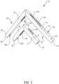
- Fig. 3 is a perspective view showing two corner elements for the system according to the first aspect of the invention.
- Fig. 3 shows a corner element 2 for the system 300 with two mutually perpendicularly arranged pipe segments 4,6 having an inner surface 8 and an opposite, outer surface 10, and a first opening 12 at a first end 14 and a second opening 16 at an opposite, second end 18.
- first pipe segment 4 and the second pipe segment 6 of the corner element 2 include a through-going elongated opening 116 between its inner surface 8 and outer surface 10.
- This opening 116 is for attachment, by securing with screws, of the corner element 2 to an internal frame in an opening in masonry.
- Fig. 3 also shows that the corner element 2 on its second pipe segment 6 at the inner surface 8 comprises a through-going threaded hole 120 for mounting a bolt.
- a connecting beam 80,86,92,96 can be locked relative to the corner element 2.
- Fig. 4a and Fig. 4b are perspective views showing a primary clip for the system according to the first aspect of the invention.
- Fig. 4a and Fig. 4b show the primary clip 106,106a,106b,106c,106d, which comprises a plate element 108 having two adjacent sides 110,112 that form an essentially right angle with each other.
- Each of the two adjacent sides 110,112 comprises a flap 114 having a first flap portion 114a and a second flap portion 114b.
- the first flap portion 114a extends from the side 110,112 in an essentially right angle from the plate element 108
- the second flap portion 114b extends from the first flap portion 114a in an essentially right angle thereto and thereby over the plate element 108.
- the clip 106,106a,106b,106c,106d can lock a covering plate 104 to the corner element 2.
- Fig. 4a and Fig. 4b also show that the first flap portion 114a comprises a through-going opening 118 having an elongated geometry, the longest extension of which is parallel to the side 110,112 of the plate element 108 from which the first flap portion 114a extends.
- the through-going opening allows a screw to pass through, which screw is to secure a corner element 2,22,42,62 in an opening in masonry.
- Fig. 6a and Fig. 6b are perspective views showing a secondary clip for the system according to the first aspect of the invention.
- Fig. 6a and Fig. 6b show that the secondary clip 122 comprises a U-shaped, flexible element 124 having a middle section 126 and two end sections 128a,128b extending from each end of the middle section 126.
- the secondary clip 122 can be used for attachment on the connecting beams 80,86,92,98 corresponding to positions between two primary clips 106, whereby the secondary clips 122 assist in holding the covering plate 104 on the frame comprising corner elements 2,22,42,62 and connecting beams 80,86,92,98 as seen in Fig. 2 .
- Fig. 7 is a plan view of a support element for the system according to the first aspect of the invention.
- Figure 7 shows the support element 130 comprising two T-joints 132 and an auxiliary beam 134.
- Each T-joint 132 comprises a first pipe segment 136 having a first end 138 and a second end 140. Between the two ends 138 and 140 is a through-going opening 142.
- the through-going opening 142 is having an extension in a first direction.
- the T-joint 132 also comprises a second pipe segment 144 having an opening 146.
- the second pipe segment of the T-joint is having an extension in a second direction, which is perpendicular to the first direction.
- the second pipe segment 144 is attached to the first pipe segment 136 by welding.
- Dimensions and geometries of the through-going opening 142 in the first pipe segment 136 are adapted to dimensions and geometries of one of the connecting beams 80,86,92,98, and dimensions and geometries of the opening 146 in the second pipe segment 144 are adapted to dimensions and geometries of the auxiliary beam 134.
- the connecting beam 80,86,92,98 can be led through the through-going opening 142 of the first pipe segment and the end of the auxiliary beam 134 can be arranged in the opening 146 in the second pipe segment 144.
- the support element 130 can stiffen the system 300.
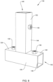
- Fig. 8 is a perspective view showing details of a T-joint for a support element for the system according to the first aspect of the invention.
- Fig. 8 shows the T-joint 132 comprising a first pipe segment 136 having a first end 138 and a second end 140, thereby defining a through-going opening 142 between them, which extends in a first direction.
- the T-joint 132 also comprises a second pipe segment 144 having an opening 146.
- the second pipe segment 144 of the T-joint is having an extension in a second direction, which is perpendicular to the first direction.
- the second pipe segment 144 is attached to the first pipe segment 136 by welding.
- Dimensions and geometries of the through-going opening 142 in the first pipe segment 136 must be adapted to dimensions and geometries of one of the connecting beams 80,86,92,98, and dimensions and geometries of the opening 146 in the second pipe segment 144 must be adapted to dimensions and geometries of the auxiliary beam 134.
- Fig. 8 also shows that the first pipe segment 136 of the T-joint 132 at an inner surface 148 thereof comprises through-going threaded holes 150 for mounting a bolt, and that the second pipe segment 144 at surface 152 comprises a through-going threaded hole 150 for mounting a bolt.
- the position of a connecting beam 80,86,92,98 can be locked relative to the first pipe segment 136 of the T-joint 132; and the position of the auxiliary beam 134 can be locked relative to the second pipe segment 144 of the T-joint 132.
Landscapes
- Engineering & Computer Science (AREA)
- Structural Engineering (AREA)
- Architecture (AREA)
- Civil Engineering (AREA)
- Mechanical Engineering (AREA)
- Connection Of Plates (AREA)
- Tents Or Canopies (AREA)
- Conveying And Assembling Of Building Elements In Situ (AREA)
- Building Awnings And Sunshades (AREA)
Abstract
Description
- The present invention generally relates to the field of building construction.
- More specifically, the present invention in a first aspect relates to a system for temporarily blocking an opening in masonry in a building construction or for forming a dust shielding wall in a room in the interior of a building construction.
- In a second aspect, the present invention relates to the use of a system according to the first aspect of the invention for temporarily blocking an opening in masonry in a building construction.
- In a third aspect, the present invention relates to the use of a system according to the first aspect for forming a dust shielding wall in a room in the interior of a building construction.
- In a fourth aspect, the present invention relates to a method for temporarily blocking an opening in masonry in a building construction using a system according to the first aspect of the invention.
- In the colder parts of Europe, such as in Scandinavia, it is common to temporarily block openings for doors and windows in masonry when walls, roofs, and any floor separations have been established. This protects the interior of the building against moisture and cold environment from outside, thus protecting both workers and materials being used for the interior finishing of the building from harmful cold and damp outside environments.
- For such temporary blocking of openings in masonry, it is common to construct a frame within the opening that serves as internal jambs. Once such a frame is established, it can subsequently be covered with wooden panels, such as plywood panels.
- If wooden panels are used for the blocking cover, one must obviously accept that light that could have been utilized from such an opening in masonry is not available.
- For this reason, reinforced transparent plastic film is sometimes used, either wholly or partially, as a replacement for covering with wooden panels.
- However, plastic film has the disadvantage of not having the same strength as wooden panels. This results in the plastic film used for covering being moved by even small gusts of wind. Such movement of the plastic film in the wind can cause much noise and in strong winds, the movement can be so violent that the plastic film will be torn apart.
- Whether using plastic film or wooden panels for temporary blocking an opening in masonry in a building construction, it cannot be avoided that the dimensions of the frame for the blocking covering must be adjusted to the size of the opening. This is a time-consuming process, as pieces of wood must be cut and adjusted in size to each specific opening in the masonry, which openings do not necessarily have exactly the same size.
- Once the construction has subsequently progressed to the point where doors and windows can be installed in the various openings in the building's masonry, the temporary frame with the blocking covering is removed without having any regard to the possibility of reusing materials. With the prior art technique for establishing temporary blocking coverings, this will accordingly generate some waste that must be disposed of. Furthermore, with the prior art types of blocking coverings, it is not possible to avoid a significant heat loss from the building's interior to the surroundings outside the building.
- However, improved systems for temporary locking of an opening in masonry in a building construction are described in the prior art.
-
WO 2005/031087 A1 accordingly describes a system for temporary blocking an opening in masonry in a building construction. This system comprises four corner elements, four side elements, and a covering plate. Each corner element comprises two pipes arranged perpendicularly to each other and a corner plate, and each side element comprises a U-shaped element having a cavity and a pipe. The system is dimensioned in such a way that the pipes in the corner elements can be slid into the pipes on an adjacent side element and in such a way that the covering plate can be slid into the cavity in the side elements' U-shape. Using wing screws, the covering plate can be fixed to the corner elements.WO 2005/031087 A1 does not describe the use of mounting clips for attaching the covering plate to the rest of the system. - Thus, there is a need for an alternative and improved system for temporary blocking of openings in masonry in buildings, which overcomes the above-mentioned disadvantages.
- It is an objective of the present invention to provide such technology.
- Accordingly, according to the first aspect of the invention, a system is provided for temporary blocking of an opening in masonry in a building construction or for forming a dust shielding wall in a room in the interior of a building construction, wherein the system comprises:
- a first upper corner element comprising two mutually perpendicularly arranged pipe segments having an inner surface and an opposite, outer surface, and a first opening at a first end and a second opening at an opposite, second end;
- a second upper corner element comprising two mutually perpendicularly arranged pipe segments having an inner surface and an opposite, outer surface, and a first opening at a first end and a second opening at an opposite, second end;
- a first lower corner element comprising two mutually perpendicularly arranged pipe segments having an inner surface and an opposite, outer surface, and a first opening at a first end and a second opening at an opposite, second end;
- a second lower corner element comprising two mutually perpendicularly arranged pipe segments having an inner surface and an opposite, outer surface, and a first opening at a first end and a second opening at an opposite, second end;
- an upper connecting beam having a first end and an opposite second end;
- a lower connecting beam having a first end and an opposite second end;
- a first vertical connecting beam having a first end and an opposite second end;
- a second vertical connecting beam having a first end and an opposite second end;
- a covering plate;
- characterized in that the system further comprises:
- four primary clips for securing said covering plate;
- wherein dimensions and geometries of the first opening at the first end of the first upper corner element are adapted to dimensions and geometries of the first end of the upper connecting beam in such a way that this first end of the upper connecting beam can be slid into the first opening at the first end of the first upper corner element;
- wherein dimensions and geometries of the second opening at the second end of the first upper corner element are adapted to dimensions and geometries of the first end of the first vertical connecting beam in such a way that this first end of the first vertical connecting beam can be slid into the second opening at the second end of the first upper corner element;
- wherein dimensions and geometries of the first opening at the first end of the second upper corner element are adapted to dimensions and geometries of the second end of the upper connecting beam in such a way that this second end of the upper connecting beam can be slid into the first opening at the first end of the second upper corner element;
- wherein dimensions and geometries of the second opening at the second end of the second upper corner element are adapted to dimensions and geometries of the first end of the second vertical connecting beam in such a way that this first end of the second vertical connecting beam can be slid into the second opening at the second end of the second upper corner element;
- wherein dimensions and geometries of the first opening at the first end of the first lower corner element are adapted to dimensions and geometries of the second end of the first vertical connecting beam in such a way that this second end of the first vertical connecting beam can be slid into the first opening at the first end of the first lower corner element;
- wherein dimensions and geometries of the second opening at the second end of the first lower corner element are adapted to dimensions and geometries of the first end of the lower connecting beam in such a way that this first end of the lower connecting beam can be slid into the second opening at the second end of the first lower corner element;
- wherein dimensions and geometries of the first opening at the first end of the second lower corner element are adapted to dimensions and geometries of the second end of the lower connecting beam in such a way that this second end of the lower connecting beam can be slid into the first opening at the first end of the second lower corner element;
- wherein dimensions and geometries of the second opening at the second end of the second lower corner element are adapted to dimensions and geometries of the second end of the second vertical connecting beam in such a way that this second end of the second vertical connecting beam can be slid into the second opening at the second end of the second lower corner element;
- wherein each of the primary clips comprises a plate element having two adjacent sides forming an essentially right angle with each other, wherein each of the two adjacent sides comprises a flap having a first flap portion and a second flap portion, wherein the first flap portion extends from the side in an essentially right angle from the plate element, and wherein the second flap portion extends from the first flap portion at an essentially right angle thereto and thereby over the plate element.
- In a second aspect, the present invention provides the use of a system according to the first aspect of the invention for temporary blocking of an opening in a wall in a building construction.
- In a third aspect, the present invention relates to the use of a system according to the first aspect for forming a dust shielding wall in a room in the interior of a building construction.
- In a fourth aspect, the present invention provides a method for temporarily blocking an opening in masonry in a building construction comprising the steps of:
- i) providing a system according to the first aspect of the invention;
- ii) assembling the system so that the first opening at the first end of the first upper corner element accommodates the first end of the upper connecting beam; and so that the second opening at the second end of the first upper corner element accommodates the first end of the first vertical connecting beam; and so that the first opening at the first end of the second upper corner element accommodates the second end of the upper connecting beam; and so that the second opening at the second end of the second upper corner element accommodates the first end of the second vertical connecting beam; and so that the first opening at the first end of the first lower corner element accommodates the second end of the first vertical connecting beam; and so that the second opening at the second end of the first lower corner element accommodates the first end of the lower connecting beam; and so that the first opening at the first end of the second lower corner element accommodates the second end of the lower connecting beam; and so that the second opening at the second end of the second lower corner element accommodates the second end of the second vertical connecting beam;
- iii) affixing the covering plate so that it covers the connecting beams and corner elements;
- iv) affixing the four primary clips at each respective corner of the arrangement obtained in step iii) so that the covering plate is being arranged between the plate element of a primary clip and a corner element;
- v) optionally affixing one or more secondary clips on an outer surface of the connecting beams corresponding to positions between two primary clips, and on the surface of the covering plate;
- vi) placing the arrangement obtained in step iv) or v) in the opening in the masonry;
- vii) adjusting the positions of the connecting beams relative to the corner elements so that each corner element's two pipe segments are resting against two perpendicular surfaces in an internal frame in the opening in the masonry;
- viii) securing the system to the opening in the masonry, such as by securing with screws thereto.
- With the invention in its various aspects, a simple, flexible, and cost-efficient means is provided for blocking an opening in masonry in a building construction, such as in the form of an opening for a window or a door.
- As the dimensions of the various elements included in the system according to the invention can be adapted to different sizes of openings in a building construction that are to be blocked, almost unlimited flexibility is achieved as to which sizes of openings in masonry with which the system fits.
- Since the connection elements for the system are configured to be able to slide inside the oppositely arranged openings in the corner elements of the system, a system with given dimensions can also be adapted to different sizes of openings in masonry in a building construction that are to be blocked.
- Furthermore, the system can be easily and non-destructively disassembled from the opening in which it is temporarily inserted, and thus the system can be reused.
- The system according to the invention is light and can easily be transported, it can in special embodiments allow significant light transmission into the interior of the building, it has lower heat loss compared to known solutions, and it can be easily made dust-tight and noise-insulated.
-
-
Fig. 1 is a plan view showing a system according to the first aspect of the invention in a disassembled state. -
Fig. 2 is a perspective view showing the system shown inFig. 1 , yet in an assembled state. -
Fig. 3 is a perspective view showing two corner elements for the system according to the first aspect of the invention. -
Fig. 4a and Fig. 4b are perspective views showing a primary clip for the system according to the first aspect of the invention. -
Fig. 5 is a perspective view showing a corner of the system according to the first aspect of the invention in an assembled state. -
Fig. 6a and Fig. 6b are perspective views showing a secondary clip for the system according to the first aspect of the invention. -
Fig. 7 is a plan view of a support element for the system according to the first aspect of the invention. -
Fig. 8 is a perspective view showing details of a T-joint for a support element for the system according to the first aspect of the invention. - In its first aspect, the present invention relates to a
system 300 for temporary blocking of an opening in masonry in a building construction or for forming a dust shielding wall in a room in the interior of a building construction, wherein the system comprises: - a first
upper corner element 2 comprising two mutually perpendicularly arrangedpipe segments inner surface 8 and an opposite,outer surface 10, and afirst opening 12 atfirst end 14 and asecond opening 16 at an opposite,second end 18; - a second
upper corner element 22 comprising two mutually perpendicularly arrangedpipe segments inner surface 28 and an opposite,outer surface 30, as well as afirst opening 32 at afirst end 34 and asecond opening 36 at an opposite,second end 38; - a first
lower corner element 42 comprising two mutually perpendicularly arrangedpipe segments inner surface 48 and an opposite,outer surface 50, as well as afirst opening 52 at afirst end 54 and asecond opening 56 at an opposite,second end 58; - a second
lower corner element 62 comprising two mutually perpendicularly arrangedpipe segments inner surface 68 and an opposite,outer surface 70, as well as afirst opening 72 at afirst end 74 and asecond opening 76 at an opposite,second end 78; - an upper connecting
beam 80 having afirst end 82 and an oppositesecond end 84; - a lower connecting
beam 86 having afirst end 88 and an oppositesecond end 90; - a first vertical connecting
beam 92 having afirst end 94 and an oppositesecond end 96; - a second vertical connecting
beam 98 having afirst end 100 and an oppositesecond end 102; - a
covering plate 104; - characterized in that the
system 300 further comprises:- four primary clips 106,106a, 106b, 106c, 106d for securing said covering
plate 104;
- four primary clips 106,106a, 106b, 106c, 106d for securing said covering
- wherein dimensions and geometries of the
first opening 12 at thefirst end 14 of the firstupper corner element 2 are adapted to dimensions and geometries of thefirst end 82 of the upper connectingbeam 80 in such a way that thisfirst end 82 of the upper connecting beam can be slid into thefirst opening 12 at thefirst end 14 of the firstupper corner element 2; - wherein dimensions and geometries of the
second opening 16 at thesecond end 18 of the firstupper corner element 2 are adapted to dimensions and geometries of thefirst end 94 of the first vertical connectingbeam 92 in such a way that thisfirst end 94 of the first vertical connectingbeam 92 can be slid into thesecond opening 16 at thesecond end 18 of the firstupper corner element 2; - wherein dimensions and geometries of the
first opening 32 at thefirst end 34 of the secondupper corner element 22 are adapted to dimensions and geometries of thesecond end 84 of the upper connectingbeam 80 in such a way that thissecond end 84 of the upper connectingbeam 80 can be slid into thefirst opening 32 at thefirst end 34 of the secondupper corner element 22; - wherein dimensions and geometries of the
second opening 36 at thesecond end 38 of the secondupper corner element 22 are adapted to dimensions and geometries of thefirst end 100 of the second vertical connectingbeam 98 in such a way that thisfirst end 100 of the second vertical connectingbeam 98 can be slid into thesecond opening 36 at thesecond end 38 of the secondupper corner element 22; - wherein dimensions and geometries of the
first opening 52 at thefirst end 54 of the firstlower corner element 42 are adapted to dimensions and geometries of thesecond end 96 of the first vertical connectingbeam 92 in such a way that thissecond end 96 of the first vertical connectingbeam 92 can be slid into thefirst opening 52 at thefirst end 54 of the firstlower corner element 42; - wherein dimensions and geometries of the
second opening 56 at thesecond end 58 of the firstlower corner element 42 are adapted to dimensions and geometries of thefirst end 88 of the lower connectingbeam 86 in such a way that thisfirst end 88 of the lower connectingbeam 86 can be slid into thesecond opening 56 at thesecond end 58 of the firstlower corner element 42; - wherein dimensions and geometries of the
first opening 72 at thefirst end 74 of the secondlower corner element 62 are adapted to dimensions and geometries of thesecond end 90 of the lower connectingbeam 86 in such a way that thissecond end 90 of the lower connectingbeam 86 can be slid into thefirst opening 72 at thefirst end 74 of the secondlower corner element 62; - wherein dimensions and geometries of the
second opening 76 at thesecond end 78 of the secondlower corner element 62 are adapted to dimensions and geometries of thesecond end 102 of the second vertical connectingbeam 98 in such a way that thissecond end 102 of the second vertical connectingbeam 98 can be slid into thesecond opening 76 at thesecond end 78 of the secondlower corner element 62; - wherein each of the primary clips 106,106a,106b,106c,106d comprises a
plate element 108 having two adjacent sides 110,112 forming an essentially right angle with each other, wherein each of the two adjacent sides 110,112 comprises aflap 114 having afirst flap portion 114a and asecond flap portion 114b, wherein thefirst flap portion 114a extends from the side 110,112 in an essentially right angle from theplate element 108, and wherein thesecond flap portion 114b extends from thefirst flap portion 114a in an essentially right angle thereto and thereby over theplate element 108. - The
system 300 can thus be assembled so that the fourcorner elements beam plate 104 can be fastened to the frame with the primary clips 106, and the system can then be inserted into an opening in masonry in a building construction. - Alternatively, the system can be used to form a dust shielding wall in the interior of a building construction.
- It should be understood that the geometry and dimensions of the
covering plate 104 during use of thesystem 300 must be adapted to the geometry and dimensions of the formed frame in its assembled state, onto which the covering plate is to be mounted. - In an embodiment of the system according to the first aspect of the invention and in respect of one or more of the four
corner elements opening 116 between its inner surface and outer surface for securing the corner element to, for example, an inner frame of an opening in masonry, such as by securing thereto using screws. - Securing the system to an internal frame in masonry with screws ensures secure attachment of the system to the masonry.
- In an embodiment of the system according to the first aspect of the invention, the through-going
opening 116 is having an elongated geometry. - Such an elongated geometry provides flexibility regarding the exact position in the internal frame wherein the screw/screws is/are placed.
- In an embodiment of the system according to the first aspect of the invention and in respect of one or more of the four primary clips 106,106a, 106b,106c, 106d, such as in respect of all primary clips, the
first flap portion 114a comprises a through-goingopening 118, such as a through-going opening with an elongated geometry, whose longest extension optionally is parallel to the side of theplate element 108 from which thefirst flap portion 114a extends. - Hereby, a screw can be screwed through the
corner element - In an embodiment of the system according to the first aspect of the invention and in respect of one or more of the four
corner elements hole 120 for mounting a bolt with a view to being able to lock the position of a connectingbeam corner element - Locking the connecting
beam corner elements - In an embodiment of the system according to the first aspect of the invention, the system further comprises a number, such as 1 - 8 or more
secondary clips 122, such as 2 - 7 secondary clips, for example 3 - 6 or 4 - 5 secondary clips, wherein in respect of one or more of these secondary clips, the secondary clip comprises a U-shaped, flexible element 124 having amiddle section 126 and twoend sections middle section 126. - The secondary clips can help secure the
covering plate 104 to the connectingbeams corner elements - In an embodiment of the system according to the first aspect of the invention, the system further comprises one or more pairs of
support elements 130, wherein each support element comprises two T-joints 132 and anauxiliary beam 134, wherein each T-joint 132 comprises afirst pipe segment 136 having afirst end 138 and asecond end 140, thereby defining a through-goingopening 142 therebetween, wherein the through-goingopening 142 is having an extension in a first direction; wherein the T-joint 132 comprises asecond pipe segment 144 having anopening 146, and wherein the second pipe segment of the T-joint is having an extension in a second direction, which is perpendicular to the first direction, and wherein thesecond pipe segment 144 is being fastened to thefirst pipe segment 136, such as by welding; wherein dimensions and geometries of the through-goingopening 142 in thefirst pipe segment 136 are being adapted to dimensions and geometries of one of the connectingbeams opening 146 in thesecond pipe segment 144 are being adapted to dimensions and geometries of theauxiliary beam 134. - One or more support elements can contribute to stiffening the frame comprising the connecting
beams corner elements - In an embodiment of the system according to the first aspect of the invention and in respect of one or both T-
joints 132 of asupport element 130, thefirst pipe segment 136 of the T-joint at aninner surface 148 thereof comprises one or more through-going threadedholes 150 for mounting a bolt with the view to being able to lock the position of a connectingbeam second pipe segment 144 of the T-joint 132 at aninner surface 152 thereof comprises one or more through-going threadedholes 150 for mounting a bolt with a view to being able to lock the position of theauxiliary beam 134 relative to the T-joint 132. - Such locking facilitates handling of the system in its assembled state.
- In an embodiment of the system according to the first aspect of the invention, the lengths of the connecting
beams auxiliary beam 134 are independently being selected from the ranges 25 - 600 cm, such as 40 - 550 cm, for example 50 - 500, such as 60 - 450 cm, such as 75 - 400, for example 100 - 350 cm, for example 150 - 300 cm, such as 200 - 250 cm. - These sizes are appropriate for most sizes of openings in masonry in a building construction that are to be bocked.
- In an embodiment of the system according to the first aspect of the invention, one or more of the connecting
beams - In an embodiment of the system according to the first aspect of the invention, the side length of the rectangular cross-section is being selected from the ranges 20 - 100 mm, such as 25 - 90 mm, for example 30 - 85 mm, such as 35 - 80 mm, for example 40 - 75 mm, such as 45 - 70 mm, for example 50 - 65 mm or 55 - 60 mm.
- These geometries and dimensions have proven suitable for the intended purpose.
- In an embodiment of the system according to the first aspect of the invention, and in respect of the first opening and/or to the second opening in one or more of the
corner elements - In an embodiment of the system according to the first aspect of the invention, the side length of the rectangular cross-section is being selected from the ranges 20 - 100 mm, such as 25 - 90 mm, for example 30 - 85 mm, such as 35 - 80 mm, for example 40 - 75 mm, such as 45 - 70 mm, for example 50 - 65 mm or 55 - 60 mm.
- These geometries and dimensions have proven suitable for the intended purpose.
- In an embodiment of the system according to the first aspect of the invention, the upper connecting
beam 80 and the lower connectingbeam 86 essentially are having the same length; and/or the first vertical connectingbeam 92 and the second vertical connectingbeam 96 essentially are having the same length. - Such designs fit most openings in masonry in a building construction that are intended for windows or doors.
- In an embodiment of the system according to the first aspect of the invention, the upper connecting
beam 80 and the lower connectingbeam 86 essentially are having the same first length, and the first vertical connectingbeam 92 and the second vertical connectingbeam 96 essentially are having the same second length, wherein the first length is different from or identical to the second length. - Such designs fit most openings in masonry in a building construction that are intended for windows or doors.
- In an embodiment of the system according to the first aspect of the invention, the four
corner elements - Designing the four
corner elements - In an embodiment of the system according to the first aspect of the invention and in respect of one or more of the four primary clips 106,106a,106b,106c,106d, the internal distance between the
second flap portion 114b and theplate element 108 corresponds to the outer thickness of the associatedcorner element covering plate 104. - Hereby, an optimal adaptation of the four primary clips 106,106a,106b,106c,106d to the rest of the system is achieved.
- In an embodiment of the system according to the first aspect of the invention, the first
upper corner element 2, the secondupper corner element 22, the firstlower corner element 42, the secondlower corner element 62, the upper connectingbeam 80, the lower connectingbeam 86, the first vertical connectingbeam 92, the second vertical connectingbeam 98, one or more of the primary clips 106,106a,106b,106c,106d, one or more of thesecondary clips 122, the T-joint 132, and/or theauxiliary beam 134 are independently being made of or comprises a metal or an alloy, such as steel or aluminum; plastic or a composite material. - Such materials have proven well suitable for the intended purpose.
- In an embodiment of the system according to the first aspect of the invention, the covering
plate 104 is being transparent or non-transparent. - A
transparent covering plate 104 allows light transmission into the interior of the building. Conversely, such light transmission into the interior of the building may not always be necessary. - In an embodiment of the system according to the first aspect of the invention, the covering
plate 104 is being made of wood or a polymer, such as acrylic or polycarbonate; or is being made of metal or an alloy; or is being made of a composite material. - These materials have proven particularly suitable as covering
plate 104. - In an embodiment of the system according to the first aspect of the invention, the covering
plate 104 is having a rectangular shape, such as a square shape with perpendicular sides. - Such shapes fit openings in masonry in a building construction that are intended for doors or windows.
- In an embodiment of the system according to the first aspect of the invention, the side length of two or more of the perpendicular sides of the covering plate is being selected from the ranges 25 - 600 cm, such as 40 - 550 cm, for example 50 - 500 cm, such as 60 - 450 cm, such as 75 - 400 cm, for example 100 - 350 cm, for example 150 - 300 cm, such as 200 - 250 cm.
- These sizes are suitable for most sizes of openings in masonry in a building construction that are to be blocked.
- In its second aspect, the present invention relates to the use of a
system 300 according to the first aspect of the invention for temporarily blocking an opening in a wall in a building construction. - In an embodiment of the use according to the second aspect of the invention, the opening in the wall is an opening for a door or for a window.
- In its third aspect, the present invention relates to the use of a
system 300 according to the first aspect of the invention for forming a dust shielding wall in a room in the interior of a building construction. - In its fourth aspect, the present invention relates to a method for temporarily blocking an opening in masonry in a building construction comprising the steps of:
- i) providing a
system 300 according to the first aspect of the invention; - ii) assembling the system so that the first opening 12 at the first end 14 of the first upper corner element 2 accommodates the first end 82 of the upper connecting beam 80; and so that the second opening 16 at the second end 18 of the first upper corner element 2 accommodates the first end 94 of the first vertical connecting beam 92; and so that the first opening 32 at the first end 34 of the second upper corner element 22 accommodates the second end 84 of the upper connecting beam 80; and so that the second opening 36 at the second end 38 of the second upper corner element 22 accommodates the first end 100 of the second vertical connecting beam 98; and so that the first opening 52 at the first end 54 of the first lower corner element 42 accommodates the second end 96 of the first vertical connecting beam 92; and so that the second opening 56 at the second end 58 of the first lower corner element 42 accommodates the first end 88 of the lower connecting beam 86; and so that the first opening 72 at the first end 74 of the second lower corner element 62 accommodates the second end 90 of the lower connecting beam 86; and so that the second opening 76 at the second end 78 of the second lower corner element 62 accommodates the second end 102 of the second vertical connecting beam 98;
- iii) affixing the
covering plate 104 so that it covers the connectingbeams corner elements - iv) affixing the four primary clips 106,106a,106b,106c,106d at each respective corner of the arrangement obtained in step iii) so that the
covering plate 104 is being arranged between theplate element 108 of a primary clip 106 and acorner element - v) optionally affixing one or more
secondary clips 122 on an outer surface of the connectingbeams covering plate 104; - vi) placing the arrangement obtained in step iv) or v) in the opening in the masonry;
- vii) adjusting the positions of the connecting
beams corner elements - viii) securing the
system 300 to the opening in the masonry, such as by securing with screws thereto. - In an embodiment of the method according to the fourth aspect of the invention, the method further comprises, after step vi), the step of:
via) in respect of one or more of thecorner elements beams holes 120 in the corner element. - With the view to better illustrating the present invention, reference is made in the following to the figures, where
Fig. 1 shows a plan view of a system according to the first aspect of the invention in a disassembled state. -
Fig. 1 shows that thesystem 300 comprises a firstupper corner element 2, a secondupper corner element 22, a firstlower corner element 42, a secondlower corner element 62, an upper connectingbeam 80, a lower connectingbeam 86, a first vertical connectingbeam 92, and a second vertical connectingbeam 98. - The
system 300 also comprises fourprimary clips 106, 106a, 106b, 106c, 106d and foursecondary clips 122, and acovering plate 104. - It can be seen in
Fig. 1 that the firstupper corner element 2 comprises two mutually perpendicularly arrangedpipe segments inner surface 8 and an opposite,outer surface 10, and afirst opening 12 at afirstend 14 and asecond opening 16 at an opposite,second end 18. - Similarly, it can be seen that the second
upper corner element 22 comprises two mutually perpendicularly arrangedpipe segments inner surface 28 and an opposite,outer surface 30, and afirst opening 32 at afirst end 34 and asecond opening 36 at an opposite,second end 38. - Additionally,
Fig. 1 shows that the firstlower corner element 42 comprises two mutually perpendicularly arrangedpipe segments inner surface 48 and an opposite,outer surface 50, and afirst opening 52 at afirst end 54 and asecond opening 56 at an opposite,second end 58. - Finally,
Fig. 1 shows that the secondlower corner element 62 comprises two mutually perpendicularly arrangedpipe segments inner surface 68 and an opposite,outer surface 70, and afirst opening 72 at afirst end 74 and asecond opening 76 at an opposite,second end 78. - It can be seen that the upper connecting
beam 80 is having afirst end 82 and an oppositesecond end 84, and that the lower connectingbeam 86 is having afirst end 88 and an oppositesecond end 90. - Similarly, it can be seen that the first vertical connecting
beam 92 is having afirst end 94 and an oppositesecond end 96, and that the second vertical connectingbeam 98 is having afirst end 100 and an oppositesecond end 102. - Dimensions and geometries of the
first opening 12 at thefirst end 14 of the firstupper corner element 2 are adapted to dimensions and geometries of thefirst end 82 of the upper connectingbeam 80 in such a way that thisfirst end 82 of the upper connecting beam can be slid into thefirst opening 12 at thefirst end 14 of the firstupper corner element 2. - Dimensions and geometries of the
second opening 16 at thesecond end 18 of the firstupper corner element 2 are similarly adapted to dimensions and geometries of thefirst end 94 of the first vertical connectingbeam 92 in such a way that thisfirst end 94 of the first vertical connectingbeam 92 can be slid into thesecond opening 16 at thesecond end 18 of the firstupper corner element 2. - Additionally, dimensions and geometries of the
first opening 32 at thefirst end 34 of the secondupper corner element 22 are adapted to dimensions and geometries of thesecond end 84 of the upper connectingbeam 80 in such a way that thissecond end 84 of the upper connectingbeam 80 can be slid into thefirst opening 32 at thefirst end 34 of the secondupper corner element 22. - Furthermore, dimensions and geometries of the
second opening 36 at thesecond end 38 of the secondupper corner element 22 are adapted to dimensions and geometries of thefirst end 100 of the second vertical connectingbeam 98 in such a way that thisfirst end 100 of the second vertical connectingbeam 98 can be slid into thesecond opening 36 at thesecond end 38 of the secondupper corner element 22. - Dimensions and geometries of the
first opening 52 at thefirst end 54 of the firstlower corner element 42 are adapted to dimensions and geometries of thesecond end 96 of the first vertical connectingbeam 92 in such a way that thissecond end 96 of the first vertical connectingbeam 92 can be slid into thefirst opening 52 at thefirst end 54 of the firstlower corner element 42. - Dimensions and geometries of the
second opening 56 at thesecond end 58 of the firstlower corner element 42 are additionally adapted to dimensions and geometries of thefirst end 88 of the lower connectingbeam 86 in such a way that thisfirst end 88 of the lower connectingbeam 86 can be slid into thesecond opening 56 at thesecond end 58 of the firstlower corner element 42;
Furthermore, dimensions and geometries of thefirst opening 72 at thefirst end 74 of the secondlower corner element 62 are adapted to dimensions and geometries of thesecond end 90 of the lower connectingbeam 86 in such a way that thissecond end 90 of the lower connectingbeam 86 can be slid into thefirst opening 72 at thefirst end 74 of the secondlower corner element 62. - Finally, dimensions and geometries of the
second opening 76 at thesecond end 78 of the secondlower corner element 62 are adapted to dimensions and geometries of thesecond end 102 of the second vertical connectingbeam 98 in such a way that thissecond end 102 of the second vertical connectingbeam 98 can be slid into thesecond opening 76 at thesecond end 78 of the secondlower corner element 62. - With these geometries and dimensions, one can achieve that opposite ends of each connecting
beam corner element Fig. 2 . - In
Fig. 2 , the fourcorner elements beams corner elements beams secondary clips 122. -
Fig. 3 is a perspective view showing two corner elements for the system according to the first aspect of the invention. -
Fig. 3 shows acorner element 2 for thesystem 300 with two mutually perpendicularly arrangedpipe segments inner surface 8 and an opposite,outer surface 10, and afirst opening 12 at afirst end 14 and asecond opening 16 at an opposite,second end 18. - It can be seen that the
first pipe segment 4 and thesecond pipe segment 6 of thecorner element 2 include a through-goingelongated opening 116 between itsinner surface 8 andouter surface 10. Thisopening 116 is for attachment, by securing with screws, of thecorner element 2 to an internal frame in an opening in masonry. -
Fig. 3 also shows that thecorner element 2 on itssecond pipe segment 6 at theinner surface 8 comprises a through-going threadedhole 120 for mounting a bolt. Thus, the position of a connectingbeam corner element 2. -
Fig. 4a and Fig. 4b are perspective views showing a primary clip for the system according to the first aspect of the invention. -
Fig. 4a and Fig. 4b show the primary clip 106,106a,106b,106c,106d, which comprises aplate element 108 having two adjacent sides 110,112 that form an essentially right angle with each other. Each of the two adjacent sides 110,112 comprises aflap 114 having afirst flap portion 114a and asecond flap portion 114b. Thefirst flap portion 114a extends from the side 110,112 in an essentially right angle from theplate element 108, and thesecond flap portion 114b extends from thefirst flap portion 114a in an essentially right angle thereto and thereby over theplate element 108. - Hereby, the clip 106,106a,106b,106c,106d can lock a
covering plate 104 to thecorner element 2. - This is shown in further detail in
Fig. 5 . -
Fig. 4a and Fig. 4b also show that thefirst flap portion 114a comprises a through-goingopening 118 having an elongated geometry, the longest extension of which is parallel to the side 110,112 of theplate element 108 from which thefirst flap portion 114a extends. - The through-going opening allows a screw to pass through, which screw is to secure a
corner element -
Fig. 6a and Fig. 6b are perspective views showing a secondary clip for the system according to the first aspect of the invention. -
Fig. 6a and Fig. 6b show that thesecondary clip 122 comprises a U-shaped, flexible element 124 having amiddle section 126 and twoend sections middle section 126. - The
secondary clip 122 can be used for attachment on the connectingbeams secondary clips 122 assist in holding thecovering plate 104 on the frame comprisingcorner elements beams Fig. 2 . -
Fig. 7 is a plan view of a support element for the system according to the first aspect of the invention. -
Figure 7 shows thesupport element 130 comprising two T-joints 132 and anauxiliary beam 134. - Each T-joint 132 comprises a
first pipe segment 136 having afirst end 138 and asecond end 140. Between the two ends 138 and 140 is a through-goingopening 142. The through-goingopening 142 is having an extension in a first direction. - The T-joint 132 also comprises a
second pipe segment 144 having anopening 146. The second pipe segment of the T-joint is having an extension in a second direction, which is perpendicular to the first direction. - The
second pipe segment 144 is attached to thefirst pipe segment 136 by welding. - Dimensions and geometries of the through-going
opening 142 in thefirst pipe segment 136 are adapted to dimensions and geometries of one of the connectingbeams opening 146 in thesecond pipe segment 144 are adapted to dimensions and geometries of theauxiliary beam 134. - Hereby, the connecting
beam auxiliary beam 134 can be arranged in theopening 146 in thesecond pipe segment 144. - In this way, the
support element 130 can stiffen thesystem 300. -
Fig. 8 is a perspective view showing details of a T-joint for a support element for the system according to the first aspect of the invention. -
Fig. 8 shows the T-joint 132 comprising afirst pipe segment 136 having afirst end 138 and asecond end 140, thereby defining a through-goingopening 142 between them, which extends in a first direction. - The T-joint 132 also comprises a
second pipe segment 144 having anopening 146. Thesecond pipe segment 144 of the T-joint is having an extension in a second direction, which is perpendicular to the first direction. - The
second pipe segment 144 is attached to thefirst pipe segment 136 by welding. - Dimensions and geometries of the through-going
opening 142 in thefirst pipe segment 136 must be adapted to dimensions and geometries of one of the connectingbeams opening 146 in thesecond pipe segment 144 must be adapted to dimensions and geometries of theauxiliary beam 134. -
Fig. 8 also shows that thefirst pipe segment 136 of the T-joint 132 at aninner surface 148 thereof comprises through-going threadedholes 150 for mounting a bolt, and that thesecond pipe segment 144 atsurface 152 comprises a through-going threadedhole 150 for mounting a bolt. - Hereby, the position of a connecting
beam first pipe segment 136 of the T-joint 132; and the position of theauxiliary beam 134 can be locked relative to thesecond pipe segment 144 of the T-joint 132. - It should be understood that all features and achievements stated above and in the appended claims with respect to one aspect of the present invention and embodiments thereof may likewise be employed in relation to the other aspects of the invention and embodiments thereof.
-
- 2
- First upper corner element
- 4
- First pipe segment of the first upper corner element
- 6
- Second pipe segment of the first upper corner element
- 8
- Inner surface of the first upper corner element
- 10
- Outer surface of the first upper corner element
- 12
- First opening at the first end of the first upper corner element
- 14
- First end of the first upper corner element
- 16
- Second opening at the second end of the first upper corner element
- 18
- Second end of the first upper corner element
- 22
- Second upper corner element
- 24
- First pipe segment of the second upper corner element
- 26
- Second pipe segment of the second upper corner element
- 28
- Inner surface of the second upper corner element
- 30
- Outer surface of the second upper corner element
- 32
- First opening at the first end of the second upper corner element
- 34
- First end of the second upper corner element
- 36
- Second opening at the second end of the second upper corner element
- 38
- Second end of the first upper corner element
- 42
- First lower corner element
- 44
- First pipe segment of the first lower corner element
- 46
- Second pipe segment of the first lower corner element
- 48
- Inner surface of the first lower corner element
- 50
- Outer surface of the first lower corner element
- 52
- First opening at the first end of the first lower corner element
- 54
- First end of the first lower corner element
- 56
- Second opening at the second end of the first lower corner element
- 58
- Second end of the first lower corner element
- 62
- Second lower corner element
- 64
- First pipe segment of the second lower corner element
- 66
- Second pipe segment of the second lower corner element
- 68
- Inner surface of the second lower corner element
- 70
- Outer surface of the second lower corner element
- 72
- First opening at the first end of the second lower corner element
- 74
- First end of the second lower corner element
- 76
- Second opening at the second end of the second lower corner element
- 78
- Second end of the first lower corner element
- 80
- Upper connecting beam
- 82
- First end of the upper connecting beam
- 84
- Second end of the upper connecting beam
- 86
- Lower connecting beam
- 88
- First end of the lower connecting beam
- 90
- Second end of the lower connecting beam
- 92
- First vertical connecting beam
- 94
- First end of the first vertical connecting beam
- 96
- Second end of the first vertical connecting beam
- 98
- Second vertical connecting beam
- 100
- First end of the second vertical connecting beam
- 102
- Second end of the second vertical connecting beam
- 104
- Covering plate
- 106,106a
- Primary clip
- 106b,106c
- Primary clip
- 106d
- Primary clip
- 108
- Plate element of primary clip
- 110,112
- Adjacent sides of plate element of clip
- 114
- Flap
- 114a
- First flap portion
- 114b
- Second flap portion
- 116
- Through-going opening in pipe segment of corner element
- 118
- Through-going opening in first flap portion of corner element
- 120
- Through-going threaded hole in pipe segment of corner element
- 122
- Secondary clip
- 124
- U-shaped flexible element
- 126
- Middle section of U-shaped flexible element
- 128a,128b
- End sections of U-shaped flexible element
- 130
- Support element
- 132
- T-joint of support element
- 134
- Auxiliary beam of support element
- 136
- First pipe segment of T-joint
- 138
- First end of the first pipe segment of T-joint
- 140
- Second end of the first pipe segment of T-joint
- 142
- Through-going opening in the first pipe segment of T-joint
- 144
- Second pipe segment ofT-joint
- 146
- Opening in the second pipe segment of T-j oint
- 148
- Inner surface of the first pipe segment of T-j oint
- 150
- Through-going threaded hole in the first or second pipe segment of T-joint
- 152
- Inner surface of the second pipe segment of T-joint
- 300
- System
Claims (15)
- A system (300) for temporarily blocking an opening in masonry in a building construction or for forming a dust shielding wall in a room within a building, wherein the system comprises:- a first upper corner element (2) comprising two mutually perpendicularly arranged pipe segments (4,6) having an inner surface (8) and an opposite, outer surface (10) as well as a first opening (12) at a first end (14) and a second opening (16) at an opposite, second end (18);- a second upper corner element (22) comprising two mutually perpendicularly arranged pipe segments (24,26) having an inner surface (28) and an opposite, outer surface (30) as well as a first opening (32) at a first end (34) and a second opening (36) at an opposite, second end (38);- a first lower corner element (42) comprising two mutually arranged pipe segments (44,46) having an inner surface (48) and an opposite, outer surface (50) as well as a first opening (52) at a first end (54) and a second opening (56) at an opposite, second end (58);- a second lower corner element (62) comprising two mutually perpendicularly arranged pipe segments (64,66) having an inner surface (68) and an opposite, outer surface (70) as well as a first opening (72) at a first end (74) and a second opening (76) at an opposite second end (78);- an upper connecting beam (80) having a first end (82) and an opposite second end (84);- a lower connecting beam (86) having a first end (88) and an opposite second end (90);- a first vertical connecting beam (92) having a first end (94) and an opposite second end (96);- a second vertical connecting beam (98) having a first end (100) and an opposite second end (102);- a covering plate (104);characterized in that the system (300) further comprises:- four primary clips (106,106a, 106b, 106c, 106d) for securing said covering plate (104);wherein the dimensions and geometries of the first opening (12) at the first end (14) of the first upper corner element (2) are adapted to the dimensions and geometries of the first end (82) of the upper connecting beam (80) in such a way that this first end (82) of the upper connecting beam can be slid into the first opening (12) at the first end (14) of the first upper corner element (2);wherein the dimensions and geometries of the second opening (16) at the second end (18) of the first upper corner element (2) are adapted to the dimensions and geometries of the first end (94) of the first vertical connecting beam (92) in such a way that this first end (94) of the first vertical connecting beam (92) can be slid into the second opening (16) at the second end (18) of the first upper corner element (2);wherein the dimensions and geometries of the first opening (32) at the first end (34) of the second upper corner element (22) are adapted to the dimensions and geometries of the second end (84) of the upper connecting beam (80) in such a way that this second end (84) of the upper connecting beam (80) can be slid into the first opening (32) at the first end (34) of the second upper corner element (22);wherein the dimensions and geometries of the second opening (36) at the second end (38) of the second upper corner element (22) are adapted to the dimensions and geometries of the first end (100) of the second vertical connecting beam (98) in such a way that this first end (100) of the second vertical connecting beam (98) can be slid into the second opening (36) at the second end (38) of the second upper corner element (22);wherein the dimensions and geometries of the first opening (52) at the first end (54) of the first lower corner element (42) are adapted to the dimensions and geometries of the second end (96) of the first vertical connecting beam (92) in such a way that this second end (96) of the first vertical connecting beam (92) can be slid into the first opening (52) at the first end (54) of the first lower corner element (42);wherein the dimensions and geometries of the second opening (56) at the second end (58) of the first lower corner element (42) are adapted to the dimensions and geometries of the first end (88) of the lower connecting beam (86) in such a way that this first end (88) of the lower connecting beam (86) can be slid into the second opening (56) at the second end (58) of the first lower corner element (42);wherein the dimensions and geometries of the first opening (72) at the first end (74) of the second lower corner element (62) are adapted to the dimensions and geometries of the second end (90) of the lower connecting beam (86) in such a way that this second end (90) of the lower connecting beam (86) can be slid into the first opening (72) at the first end (74) of the second lower corner element (62);wherein the dimensions and geometries of the second opening (76) at the second end (78) of the second lower corner element (62) are adapted to the dimensions and geometries of the second end (102) of the second vertical connecting beam (98) in such a way that this second end (102) of the second vertical connecting beam (98) can be slid into the second opening (76) at the second end (78) of the second lower corner element (62);wherein each of the primary clips (106,106a, 106b, 106c, 106d) comprises a plate element (108) having two adjacent sides (110,112) forming an essentially right angle with each other, wherein each of the two adjacent sides (110,112) comprises a flap (114) having a first flap portion (114a) and a second flap portion (114b), wherein the first flap portion (114a) extends from the side (110,112) at an essentially right angle from the plate element (108), and wherein the second flap portion (114b) extends from the first flap portion (114a) at an essentially right angle thereto and thereby over the plate element (108).
- A system (300) according to claim 1, wherein in respect of one or more of the four corner elements (2,22,42,62), such as in respect of all corner elements, said first and/or said second pipe segment thereof comprises a through-going opening (116) between its inner surface and outer surface for securing the corner element to, for example, an inner frame of an opening in masonry, such as by securing thereto with screws; optionally wherein the through-going opening (116) is having an elongated geometry; and/or
optionally wherein in respect of one or more of the four primary clips (106,106a,106b,106c,106d), such as in respect of all primary clips, the first flap portion (114a) comprises a through-going opening (118), such as a through-going opening with an elongate geometry, whose longest extension optionally is being parallel to the side of the plate element (108), from which the first flap portion (114a) extends. - A system (300) according to any of the claims 1 or 2, wherein in respect of one or more of the four corner elements (2,22,42,62), such as in respect of all corner elements, the first and/or second pipe segment, at its inner surface, comprises a through-going threaded hole (120) for mounting a bolt with a view to being able to lock the position of a connecting beam (80,86,92,96) in relation to the corner element (2,22,42,62).
- A system (300) according to any of the preceding claims, wherein the system further comprises a number, such as 1 - 8 or more secondary clips (122), such as 2 - 7 secondary clips, for example 3 - 6 or 4 - 5 secondary clips, wherein in respect of one or more of these secondary clips, the secondary clip comprises a U-shaped, flexible element (124) having a middle section (126) and two end sections (128a, 128b), extending from each end of the middle section (126);
and/orwherein the system further comprises one or more pairs of support elements (130), wherein each support element comprises two T-joints (132) and an auxiliary beam (134), where each T-joint (132) comprises a first pipe segment (136) having a first end (138) and a second end (140), thereby defining a through-going opening (142) therebetween; wherein the through-going opening 142 is having an extension in a first direction; wherein the T-joint (132) comprises a second pipe segment (144) having an opening (146), and wherein the second pipe segment of the T-joint is having an extension in a second direction which is being perpendicular to the first direction, and wherein the second pipe segment (144) is being fastened to the first pipe segment (136), such as by welding; wherein the dimensions and geometries of the through-going opening (142) in the first pipe segment (136) are being adapted to the dimensions and geometries of one of the connecting beams (80,86,92,98), and wherein the dimensions and geometries of the opening (146) in the second pipe segment (144) are being adapted to the dimensions and geometries of the auxiliary beam (134);wherein in respect of one or both Tjoints (132) of a support element (130), the first pipe segment (136) of the T-joint at an inner surface (148) thereof optionally comprises one or more through-going threaded holes (150) for mounting a bolt with the view to being able to lock the position of a connecting beam (80,86,92,98) in relation to the T-joint (132); and/or wherein the second pipe segment (144) of the T-joint (132) at an inner surface (152) thereof optionally comprises one or more through-going threaded holes (150) for mounting a bolt with the view to being able to lock the position of the auxiliary beam (134) in relation to the T-joint (132). - A system (300) according to any of the preceding claims, wherein one or more of the connecting beams (80,86,92,98) independently is/are having a rectangular cross-section with two perpendicular sides, such as a square cross-section.
- A system (300) according to any of the preceding claims, wherein in respect of the first opening and/or the second opening in one or more of the corner elements (2,22,42,62), the opening/openings is/are having a rectangular cross-section with two perpendicular sides, such as a square cross-section.
- A system (300) according to any of the preceding claims, wherein the upper connecting beam (80) and the lower connecting beam (86) essentially are having the same length; and/or wherein the first vertical connecting beam (92) and the second vertical connecting beam (96) essentially are having the same length; optionally wherein the upper connecting beam (80) and the lower connecting beam (86) essentially are having the same first length, and wherein the first vertical connecting beam (92) and the second vertical connecting beam (96) essentially are having the same second length, wherein the first length is different from or identical to the second length.
- A system (300) according to any of the preceding claims, wherein in respect of one or more of the four primary clips (106,106a, 106b, 106c, 106d), the inner distance between the second flap portion (114b) and the plate element (108) corresponds to the outer thickness of the associated corner element (2,22,42,62) plus the thickness of the covering plate (104).
- A system (300) according to any of the preceding claims, wherein the first upper corner element (2), the second upper corner element (22), the first lower corner element (42), the second lower corner element (62), the upper connecting beam (80), the lower connecting beam (86), the first vertical connecting beam (92), the second vertical connecting beam (98), one or more of the primary clips (106,106a,106b,106c,106d), one or more of the secondary clips (122), the T-joint (132) and/or the auxiliary beam (134) independently are being made of or comprise a metal or an alloy, such as steel or aluminum; plastic or a composite material.
- A system (300) according to any of the preceding claims, wherein the covering plate (104) is being transparent or non-transparent; optionally wherein the covering plate (104) is being made of wood or a polymer, such as acrylic or polycarbonate; or is being made of metal or an alloy; or is made of a composite material.
- Use of a system (300) according to any of the claims 1 - 10 for temporarily blocking an opening in a wall in a building construction.
- Use according to claim 11, wherein the opening in the wall is an opening for a door or a window.
- Use of a system (300) according to any of the claims 1 - 10 for forming a dust shielding wall in a room in the interior of a building.
- A method for temporarily blocking an opening in masonry in a building construction comprising the steps:i) providing a system (300) according to any of the claims 1 - 10;ii) assembling the system so that the first opening (12) at the first end (14) of the first upper corner element (2) accommodates the first end (82) of the upper connecting beam (80); and so that the second opening (16) at the second end (18) of the first upper corner element (2) accommodates the first end (94) of the first vertical connecting beam (92); and so that the first opening (32) at the first end (34) of the second upper corner element (22) accommodates the second end (84) of the upper connecting beam (80); and so that the second opening (36) at the second end (38) of the second upper corner element (22) accommodates the first end (100) of the second vertical connecting beam (98); and so that the first opening (52) at the first end (54) of the first lower corner element (42) accommodates the second end (96) of the first vertical connecting beam (92); and so that the second opening (56) at the second end (58) of the first lower corner element (42) accommodates the first end (88) of the lower connecting beam (86); and so that the first opening (72) at the first end (74) of the second lower corner element (62) accommodates the second end (90) of the lower connecting beam (86); and so that the second opening (76) at the second end (78) of the second lower corner element (62) accommodates the second end (102) of the second vertical connecting beam (98);iii) affixing the covering plate (104) so that it covers the connecting beams (80,86,92,98) and the corner elements (2,22,42,62);iv) affixing the four primary clips (106,106a, 106b, 106c, 106d) in each respective corner of the arrangement obtained in step iii) so that the covering plate (104) is being arranged between the plate element (108) of a primary clip (106) and a corner element (2,22,42,62);v) optionally affixing one or more secondary clips (122) on an outer surface of the connecting beams (80,86,92,98) corresponding to positions between two primary clips (106), and on the surface of the covering plate (104);vi) placing the arrangement obtained in step iv) or v) in the opening in the masonry;vii) adjusting the positions of the connecting beams (80,86,92,98) relative to the corner elements (2,22,42,62) so that each corner element's two pipe segments are resting against two perpendicular surfaces of an inner frame in the opening in the masonry;viii) securing the system (300) to the opening in the masonry, such as by securing with screws thereto.
- A method according to claim 14 further comprising, after step vi), the step of:
via) in respect of one or more of the corner elements (2,22,42,62), securing said corner element to one or two connecting beams (80,86,92,98) by screwing one or more bolts into the through-going threaded holes (120) in the corner element.
Applications Claiming Priority (1)
| Application Number | Priority Date | Filing Date | Title |
|---|---|---|---|
| DKPA202330019A DK181595B1 (en) | 2023-05-09 | 2023-05-09 | System for temporary blinding of an opening in a masonry in a building |
Publications (3)
| Publication Number | Publication Date |
|---|---|
| EP4461915A1 true EP4461915A1 (en) | 2024-11-13 |
| EP4461915C0 EP4461915C0 (en) | 2025-04-23 |
| EP4461915B1 EP4461915B1 (en) | 2025-04-23 |
Family
ID=91067164
Family Applications (1)
| Application Number | Title | Priority Date | Filing Date |
|---|---|---|---|
| EP24174728.6A Active EP4461915B1 (en) | 2023-05-09 | 2024-05-08 | A system for temporarily blocking an opening in masonry in a building construction or for forming a dust shielding wall in a room within a building |
Country Status (3)
| Country | Link |
|---|---|
| EP (1) | EP4461915B1 (en) |
| DK (1) | DK181595B1 (en) |
| PL (1) | PL4461915T3 (en) |
Citations (8)
| Publication number | Priority date | Publication date | Assignee | Title |
|---|---|---|---|---|
| US3516215A (en) * | 1967-03-31 | 1970-06-23 | Edward A Smith | Corner bracket and structures fabricated thereby |
| EP0605068A1 (en) * | 1992-12-30 | 1994-07-06 | Hans Dieter Richter | Support for frames closing an opening |
| US20040250475A1 (en) * | 2003-06-16 | 2004-12-16 | Seaman Brian B. | Door frame kit |
| WO2005031087A1 (en) | 2003-09-30 | 2005-04-07 | Hansen Soeren | A temporary closure |
| US20130239497A1 (en) * | 2012-03-19 | 2013-09-19 | Raymond Burleson | System for protecting openings on building structures |
| US9217276B1 (en) * | 2013-12-27 | 2015-12-22 | Cyprexx Services, LLC | Triangular flange bracket for attaching corners of transparent plastic panels over window and door openings |
| WO2019171264A1 (en) * | 2018-03-06 | 2019-09-12 | Kaousmart | Device for closing an opening in the wall of a building |
| WO2021122714A1 (en) * | 2019-12-17 | 2021-06-24 | Lasse Ramskov Holding Aps | Adjustable mounting, and a structural frame comprising said mounting |
Family Cites Families (2)
| Publication number | Priority date | Publication date | Assignee | Title |
|---|---|---|---|---|
| US6886300B2 (en) * | 2002-08-22 | 2005-05-03 | Wayne-Dalton Corp. | Tensioned fabric storm protection panel |
| US8756883B2 (en) * | 2011-11-07 | 2014-06-24 | Door & Window Guard Systems, Inc. | Assembly and method for securing a door opening or other opening of a building structure |
-
2023
- 2023-05-09 DK DKPA202330019A patent/DK181595B1/en active IP Right Grant
-
2024
- 2024-05-08 PL PL24174728.6T patent/PL4461915T3/en unknown
- 2024-05-08 EP EP24174728.6A patent/EP4461915B1/en active Active
Patent Citations (8)
| Publication number | Priority date | Publication date | Assignee | Title |
|---|---|---|---|---|
| US3516215A (en) * | 1967-03-31 | 1970-06-23 | Edward A Smith | Corner bracket and structures fabricated thereby |
| EP0605068A1 (en) * | 1992-12-30 | 1994-07-06 | Hans Dieter Richter | Support for frames closing an opening |
| US20040250475A1 (en) * | 2003-06-16 | 2004-12-16 | Seaman Brian B. | Door frame kit |
| WO2005031087A1 (en) | 2003-09-30 | 2005-04-07 | Hansen Soeren | A temporary closure |
| US20130239497A1 (en) * | 2012-03-19 | 2013-09-19 | Raymond Burleson | System for protecting openings on building structures |
| US9217276B1 (en) * | 2013-12-27 | 2015-12-22 | Cyprexx Services, LLC | Triangular flange bracket for attaching corners of transparent plastic panels over window and door openings |
| WO2019171264A1 (en) * | 2018-03-06 | 2019-09-12 | Kaousmart | Device for closing an opening in the wall of a building |
| WO2021122714A1 (en) * | 2019-12-17 | 2021-06-24 | Lasse Ramskov Holding Aps | Adjustable mounting, and a structural frame comprising said mounting |
Also Published As
| Publication number | Publication date |
|---|---|
| DK202330019A1 (en) | 2024-06-14 |
| PL4461915T3 (en) | 2025-10-06 |
| EP4461915C0 (en) | 2025-04-23 |
| DK181595B1 (en) | 2024-06-14 |
| EP4461915B1 (en) | 2025-04-23 |
Similar Documents
| Publication | Publication Date | Title |
|---|---|---|
| US8615942B2 (en) | Metal header frame for a building wall | |
| CA2580450C (en) | Knock-down roof curb | |
| PL193842B1 (en) | Cladding board mounting system | |
| US4283900A (en) | Corner brace for building construction | |
| EP4461915A1 (en) | A system for temporarily blocking an opening in masonry in a building construction or for forming a dust shielding wall in a room within a building | |
| EP0436632A1 (en) | Prefabricated building. | |
| US20020139063A1 (en) | Roof curb with integral burglar bars | |
| EP0111857B1 (en) | Construction system for covering or subdividing a space | |
| KR20200112459A (en) | Bracket for base truss | |
| KR100485363B1 (en) | Marine fire door | |
| US20070119843A1 (en) | Wall framing system | |
| US20200102741A1 (en) | Modular wall and roof pocket system | |
| JPH06288146A (en) | Construction method for entrance, opening section and structure thereof | |
| JP7135259B2 (en) | Double-sided outer wall structure of building and fixing method of double-sided outer wall of building | |
| US20240183214A1 (en) | Pre-hung door assembly and method for the same | |
| JP3858420B2 (en) | Mounting structure of the roof | |
| JP2012072604A (en) | Reinforcing panel and reinforcing structure | |
| JPS636351Y2 (en) | ||
| JP2024080783A (en) | Non-welded fastening structure and non-welded fastening method | |
| KR200164477Y1 (en) | Combining structure of stone panel for internal and external decoration of the building | |
| JP4939177B2 (en) | Equipment for assembling indoor and outdoor components in a shoji composite downpipe | |
| JPH0642085A (en) | Opening frame fixing structure for outside wall | |
| JP2026027866A (en) | Wall panels and wall panel installation methods | |
| JPS631682Y2 (en) | ||
| JP3847034B2 (en) | Vertical frame mounting bracket |
Legal Events
| Date | Code | Title | Description |
|---|---|---|---|
| PUAI | Public reference made under article 153(3) epc to a published international application that has entered the european phase |
Free format text: ORIGINAL CODE: 0009012 |
|
| STAA | Information on the status of an ep patent application or granted ep patent |
Free format text: STATUS: THE APPLICATION HAS BEEN PUBLISHED |
|
| AK | Designated contracting states |
Kind code of ref document: A1 Designated state(s): AL AT BE BG CH CY CZ DE DK EE ES FI FR GB GR HR HU IE IS IT LI LT LU LV MC ME MK MT NL NO PL PT RO RS SE SI SK SM TR |
|
| STAA | Information on the status of an ep patent application or granted ep patent |
Free format text: STATUS: REQUEST FOR EXAMINATION WAS MADE |
|
| 17P | Request for examination filed |
Effective date: 20241127 |
|
| RBV | Designated contracting states (corrected) |
Designated state(s): AL AT BE BG CH CY CZ DE DK EE ES FI FR GB GR HR HU IE IS IT LI LT LU LV MC ME MK MT NL NO PL PT RO RS SE SI SK SM TR |
|
| GRAP | Despatch of communication of intention to grant a patent |
Free format text: ORIGINAL CODE: EPIDOSNIGR1 |
|
| STAA | Information on the status of an ep patent application or granted ep patent |
Free format text: STATUS: GRANT OF PATENT IS INTENDED |
|
| INTG | Intention to grant announced |
Effective date: 20250124 |
|
| GRAS | Grant fee paid |
Free format text: ORIGINAL CODE: EPIDOSNIGR3 |
|
| GRAA | (expected) grant |
Free format text: ORIGINAL CODE: 0009210 |
|
| STAA | Information on the status of an ep patent application or granted ep patent |
Free format text: STATUS: THE PATENT HAS BEEN GRANTED |
|
| AK | Designated contracting states |
Kind code of ref document: B1 Designated state(s): AL AT BE BG CH CY CZ DE DK EE ES FI FR GB GR HR HU IE IS IT LI LT LU LV MC ME MK MT NL NO PL PT RO RS SE SI SK SM TR |
|
| REG | Reference to a national code |
Ref country code: GB Ref legal event code: FG4D |
|
| REG | Reference to a national code |
Ref country code: CH Ref legal event code: EP |
|
| REG | Reference to a national code |
Ref country code: DE Ref legal event code: R096 Ref document number: 602024000074 Country of ref document: DE |
|
| REG | Reference to a national code |
Ref country code: IE Ref legal event code: FG4D |
|
| U01 | Request for unitary effect filed |
Effective date: 20250512 |
|
| U07 | Unitary effect registered |
Designated state(s): AT BE BG DE DK EE FI FR IT LT LU LV MT NL PT RO SE SI Effective date: 20250516 |
|
| PG25 | Lapsed in a contracting state [announced via postgrant information from national office to epo] |
Ref country code: ES Free format text: LAPSE BECAUSE OF FAILURE TO SUBMIT A TRANSLATION OF THE DESCRIPTION OR TO PAY THE FEE WITHIN THE PRESCRIBED TIME-LIMIT Effective date: 20250423 |
|
| PG25 | Lapsed in a contracting state [announced via postgrant information from national office to epo] |
Ref country code: GR Free format text: LAPSE BECAUSE OF FAILURE TO SUBMIT A TRANSLATION OF THE DESCRIPTION OR TO PAY THE FEE WITHIN THE PRESCRIBED TIME-LIMIT Effective date: 20250724 Ref country code: NO Free format text: LAPSE BECAUSE OF FAILURE TO SUBMIT A TRANSLATION OF THE DESCRIPTION OR TO PAY THE FEE WITHIN THE PRESCRIBED TIME-LIMIT Effective date: 20250723 |
|
| PG25 | Lapsed in a contracting state [announced via postgrant information from national office to epo] |
Ref country code: HR Free format text: LAPSE BECAUSE OF FAILURE TO SUBMIT A TRANSLATION OF THE DESCRIPTION OR TO PAY THE FEE WITHIN THE PRESCRIBED TIME-LIMIT Effective date: 20250423 |
|
| PG25 | Lapsed in a contracting state [announced via postgrant information from national office to epo] |
Ref country code: RS Free format text: LAPSE BECAUSE OF FAILURE TO SUBMIT A TRANSLATION OF THE DESCRIPTION OR TO PAY THE FEE WITHIN THE PRESCRIBED TIME-LIMIT Effective date: 20250723 |
|
| PG25 | Lapsed in a contracting state [announced via postgrant information from national office to epo] |
Ref country code: IS Free format text: LAPSE BECAUSE OF FAILURE TO SUBMIT A TRANSLATION OF THE DESCRIPTION OR TO PAY THE FEE WITHIN THE PRESCRIBED TIME-LIMIT Effective date: 20250823 |
|
| U21 | Renewal fee for the european patent with unitary effect paid with additional fee |
Year of fee payment: 2 Effective date: 20250929 |
|
| PG25 | Lapsed in a contracting state [announced via postgrant information from national office to epo] |
Ref country code: SM Free format text: LAPSE BECAUSE OF FAILURE TO SUBMIT A TRANSLATION OF THE DESCRIPTION OR TO PAY THE FEE WITHIN THE PRESCRIBED TIME-LIMIT Effective date: 20250423 |
|
| PG25 | Lapsed in a contracting state [announced via postgrant information from national office to epo] |
Ref country code: CZ Free format text: LAPSE BECAUSE OF FAILURE TO SUBMIT A TRANSLATION OF THE DESCRIPTION OR TO PAY THE FEE WITHIN THE PRESCRIBED TIME-LIMIT Effective date: 20250423 |
|
| PG25 | Lapsed in a contracting state [announced via postgrant information from national office to epo] |
Ref country code: SK Free format text: LAPSE BECAUSE OF FAILURE TO SUBMIT A TRANSLATION OF THE DESCRIPTION OR TO PAY THE FEE WITHIN THE PRESCRIBED TIME-LIMIT Effective date: 20250423 |
|
| PG25 | Lapsed in a contracting state [announced via postgrant information from national office to epo] |
Ref country code: MC Free format text: LAPSE BECAUSE OF FAILURE TO SUBMIT A TRANSLATION OF THE DESCRIPTION OR TO PAY THE FEE WITHIN THE PRESCRIBED TIME-LIMIT Effective date: 20250423 |
|
| PLBE | No opposition filed within time limit |
Free format text: ORIGINAL CODE: 0009261 |
|
| STAA | Information on the status of an ep patent application or granted ep patent |
Free format text: STATUS: NO OPPOSITION FILED WITHIN TIME LIMIT |
|
| REG | Reference to a national code |
Ref country code: CH Ref legal event code: L10 Free format text: ST27 STATUS EVENT CODE: U-0-0-L10-L00 (AS PROVIDED BY THE NATIONAL OFFICE) Effective date: 20260304 |
|
| 26N | No opposition filed |
Effective date: 20260126 |