EP4461853A1 - System and method for the production of a shaded carded yarn - Google Patents
System and method for the production of a shaded carded yarn Download PDFInfo
- Publication number
- EP4461853A1 EP4461853A1 EP24174888.8A EP24174888A EP4461853A1 EP 4461853 A1 EP4461853 A1 EP 4461853A1 EP 24174888 A EP24174888 A EP 24174888A EP 4461853 A1 EP4461853 A1 EP 4461853A1
- Authority
- EP
- European Patent Office
- Prior art keywords
- belt
- fiber blend
- intimate fiber
- hooked
- intimate
- Prior art date
- Legal status (The legal status is an assumption and is not a legal conclusion. Google has not performed a legal analysis and makes no representation as to the accuracy of the status listed.)
- Granted
Links
Images


Classifications
-
- D—TEXTILES; PAPER
- D01—NATURAL OR MAN-MADE THREADS OR FIBRES; SPINNING
- D01G—PRELIMINARY TREATMENT OF FIBRES, e.g. FOR SPINNING
- D01G23/00—Feeding fibres to machines; Conveying fibres between machines
- D01G23/02—Hoppers; Delivery shoots
- D01G23/04—Hoppers; Delivery shoots with means for controlling the feed
-
- D—TEXTILES; PAPER
- D01—NATURAL OR MAN-MADE THREADS OR FIBRES; SPINNING
- D01G—PRELIMINARY TREATMENT OF FIBRES, e.g. FOR SPINNING
- D01G13/00—Mixing, e.g. blending, fibres; Mixing non-fibrous materials with fibres
-
- D—TEXTILES; PAPER
- D01—NATURAL OR MAN-MADE THREADS OR FIBRES; SPINNING
- D01G—PRELIMINARY TREATMENT OF FIBRES, e.g. FOR SPINNING
- D01G15/00—Carding machines or accessories; Card clothing; Burr-crushing or removing arrangements associated with carding or other preliminary-treatment machines
- D01G15/02—Carding machines
- D01G15/12—Details
- D01G15/40—Feeding apparatus
-
- D—TEXTILES; PAPER
- D01—NATURAL OR MAN-MADE THREADS OR FIBRES; SPINNING
- D01G—PRELIMINARY TREATMENT OF FIBRES, e.g. FOR SPINNING
- D01G15/00—Carding machines or accessories; Card clothing; Burr-crushing or removing arrangements associated with carding or other preliminary-treatment machines
- D01G15/02—Carding machines
- D01G15/12—Details
- D01G15/46—Doffing or like arrangements for removing fibres from carding elements; Web-dividing apparatus; Condensers
- D01G15/52—Web-dividing arrangements
-
- D—TEXTILES; PAPER
- D01—NATURAL OR MAN-MADE THREADS OR FIBRES; SPINNING
- D01G—PRELIMINARY TREATMENT OF FIBRES, e.g. FOR SPINNING
- D01G21/00—Combinations of machines, apparatus, or processes, e.g. for continuous processing
-
- D—TEXTILES; PAPER
- D02—YARNS; MECHANICAL FINISHING OF YARNS OR ROPES; WARPING OR BEAMING
- D02G—CRIMPING OR CURLING FIBRES, FILAMENTS, THREADS, OR YARNS; YARNS OR THREADS
- D02G3/00—Yarns or threads, e.g. fancy yarns; Processes or apparatus for the production thereof, not otherwise provided for
- D02G3/02—Yarns or threads characterised by the material or by the materials from which they are made
- D02G3/04—Blended or other yarns or threads containing components made from different materials
-
- D—TEXTILES; PAPER
- D02—YARNS; MECHANICAL FINISHING OF YARNS OR ROPES; WARPING OR BEAMING
- D02G—CRIMPING OR CURLING FIBRES, FILAMENTS, THREADS, OR YARNS; YARNS OR THREADS
- D02G3/00—Yarns or threads, e.g. fancy yarns; Processes or apparatus for the production thereof, not otherwise provided for
- D02G3/22—Yarns or threads characterised by constructional features, e.g. blending, filament/fibre
- D02G3/34—Yarns or threads having slubs, knops, spirals, loops, tufts, or other irregular or decorative effects, i.e. effect yarns
- D02G3/346—Yarns or threads having slubs, knops, spirals, loops, tufts, or other irregular or decorative effects, i.e. effect yarns with coloured effects, i.e. by differential dyeing process
Definitions
- the present invention relates to a system for obtaining a shaded carded yarn and a method for obtaining a shaded carded yarn, in which the yarn consists of natural, synthetic, artificial, aramid, fibers, etc., of different types and coloring, the composition of which is controlled and adjusted with high precision.
- Such a blending step of the prior art provides loading the mass fibers into a blending cell provided with fans which generate vortexes that move, aggregate and mix the different fibers.
- blends are produced, i.e., aggregates of mixed fibers, which are substantially uniform, which are later intended for the carding, and therefore will feed a carding machine, or "carder".
- the known carding process, and the initial blending step in particular do not allow obtaining shaded carded yarns, and in particular which shade is predetermined, controlled and adjusted, because the blends obtained from the prior art, which are further used to obtain the yarn, are substantially the same.
- a system for obtaining a shaded carded yarn is generally indicated by reference numeral 1.
- System 1 is usable to perform a method for obtaining a shaded carded yarn.
- the method for obtaining a shaded carded yarn comprises the following steps:
- a method thus configured allows conveying the different types of intimate fiber blends 2 to a carding station 5 in a selective and controlled manner in order to then obtain a shaded carded yarn with predetermined composition and shade, controlled and adjusted with high precision.
- such a method prevents an undesired mixing between intimate fiber blends 2 having different coloring or type before they are transferred to the carding station 5. Indeed, such an undesired mixing would affect the resulting yarn and not allow controlling or determining the shade of the final carded yarn in advance.
- a method thus configured ensures control over the end results, allowing a carded yarn with the desired shade to be obtained with high precision.
- Intimate fiber blend means a set of mixed and/or tangled fibers. Specifically, the intimate fiber blends of the present invention are obtained by means of composition with very precise and well-defined percentages of fibers so as to obtain the desired intimate fiber blends having an intimate mixture of different fibers and/or colors.
- belt 4 comprises, in sequence, a conveyor belt 21, an extractor belt 22, a hooked loading belt 23, and a hooked unloading belt 25.
- the step of unloading the first intimate fiber blend 2' from the respective bin 3 onto a belt 4 comprises the step of unloading the first intimate fiber blend 2' from the respective bin 3 onto the conveyor belt 21.
- step of transferring the first intimate fiber blend 2' from belt 4 to a carding station 5 comprises the steps of:
- belt 4 further comprises a hooked meter belt 24.
- the hooked meter belt 24 is positioned at the hooked loading belt 23, at an end of the hooked loading belt 23 opposite to the extractor belt 22.
- the step of transferring the first intimate fiber blend 2' from belt 4 to a carding station 5 comprises the step of leveling, by the hooked meter belt 24, the thickness of the first intimate fiber blend 2' transported by the hooked loading belt 23 to the hooked unloading belt 25.
- the leveling of the thickness of the first intimate fiber blend 2' is performed by rotating the hooked meter belt 24 in the same direction as the rotation direction of the hooked loading belt 23.
- Thickness means the thickness of the intimate fiber blend 2 measured in direction transverse to the hooked loading belt 23 along which the intimate fiber blend 2 is transported.
- such a configuration avoids transferring, to the carding station 5, "blocks" of intimate fiber blend 2 which are too thick and would affect the end result.
- the step of extracting the first intimate fiber blend 2' from the hooked loading belt 23 and unloading the first intimate fiber blend 2' to the carding station 5 is performed by a rotation of the hooked unloading belt 25 in the direction opposite to the rotation direction of the hooked loading belt 23.
- the hooks of the hooked unloading belt 25 intersect with the hooks of the hooked loading belt 23 to hook the first intimate fiber blend 2' from the hooked loading belt 23 and unload the first intimate fiber blend 2' to the carding station 5.
- the first intimate fiber blend 2' is unloaded to a metering device 6.
- the extractor belt 22 rotates in the same direction as the conveyor belt 21.
- the rotation speed of the extractor belt 22 is from two to ten times greater than the rotation speed of the conveyor belt 21.
- the rotation speed of the extractor belt 22 is from two to ten times greater than the rotation speed of the conveyor belt 21.
- such a configuration ensures a controllable and monitorable transfer of the intimate fiber blend 2 to the carding station 5.
- system 1 comprises, in sequence, a first photocell 26, a second photocell 27, a third photocell 28, and a fourth photocell 29.
- the first photocell 26 is positioned at an end of the conveyor belt 21 facing the extractor belt 22.
- the second photocell 27 is positioned at the extractor belt 22.
- the third photocell 28 is positioned at an end of the hooked loading belt 23 facing the extractor belt 22.
- the fourth photocell 29 is positioned at the hooked loading belt 23, above the third photocell 28.
- first, second, third and fourth photocells 26, 27, 28, 29 are configured to detect the presence or absence of an intimate fiber blend 2 or residuals of intimate fiber blend 2 on the respective belt 21, 22, 23, 24, 25 at which they are positioned.
- the step of transferring the first intimate fiber blend 2' from belt 4 to a carding station 5 comprises the following steps:
- such a configuration ensures the complete and controlled transfer of the intimate fiber blend 2 to the carding station 5, thus avoiding undesired mixing with different intimate fiber blends 2.
- system 1 comprises a movable thrust wall 15.
- the movable thrust wall 15 is positioned at the conveyor belt 21 and is configured to translate in a direction parallel to the conveyor belt 21 towards the extractor belt 22, from a stroke start position to a stroke end position, and vice versa.
- the stroke end position is positioned substantially at the first photocell 26.
- the step of transferring the first intimate fiber blend 2' from belt 4 to a carding station 5 comprises the following steps:
- such a configuration ensures the complete and controlled transfer of the intimate fiber blend 2 to the carding station 5, thus avoiding undesired mixing with different intimate fiber blends 2.
- the rotation speed of the hooked loading belt 23 is adjusted as a function of the amount of intimate fiber blend 2 on belt 4.
- a decrease in the amount of intimate fiber blend 2 on belt 4 corresponds to an increase in the rotation speed of the hooked loading belt 23.
- the rotation speed of the hooked loading belt 23 is inversely proportional to the rotation speed of the hooked meter belt 24.
- a decrease in the amount of intimate fiber blend 2 on belt 4 corresponds to an increase in the rotation speed of the hooked loading belt 23 and a related decrease in the rotation speed of the hooked meter belt 24.
- an increase in the amount of intimate fiber blend 2 on belt 4 corresponds to a decrease in the rotation speed of the hooked loading belt 23 and a related increase in the rotation speed of the hooked meter belt 24.
- such a configuration ensures transferring the intimate fiber blend 2 to the carding station 5 within the times established by the carding station 5 for receiving the intimate fiber blend 2, and simultaneously avoids transferring too thick an intimate fiber blend 2 to the carding station 5, thus avoiding the end result from being affected.
- system 1 comprises a metering device 6.
- the metering device 6 is an electronic scale.
- the metering device 6 is configured to receive portions of intimate fiber blend 2 from the hooked unloading belt 25, dose and transfer the portions of intimate fiber blend 2 to the carding station 5.
- the step of transferring the first intimate fiber blend 2' from belt 4 to a carding station 5 comprises the steps of:
- such a configuration allows synchronizing the controlled transfer of intimate fiber blend 2 with the cycle time determinable by the carding station 5, thus avoiding undesired mixing of the intimate fiber blends 2 and avoiding too much material or too thick an intimate fiber blend 2 to be transferred to the carding station 5, which would affect the end result. Too thick an intimate fiber blend 2 could be generated if the intimate fiber blend 2 were transferred too quickly to the carding station 5, i.e., with a shorter actual time than the cycle time.
- system 1 comprises at least one barrier gate 30 interposed between the hooked unloading belt 25 and the metering device 6.
- the step of transferring the first intimate fiber blend 2' from belt 4 to a carding station 5 comprises the steps of:
- the step of loading the plurality of intimate fiber blends 2 into respective containment bins 3 so that each bin 3 contains a single intimate fiber blend 2 comprises providing a pneumatic supply system 8, comprising a supply duct 9 connected to a carriage 10 and a pneumatic pumping system comprising a fan 13 and a cyclone 16.
- Cyclone 16 is interposed between bin 3 and fan 13 and is configured to slow down the intimate fiber blend 2 conveyed by fan 13 and expel excess air conveyed by fan 13.
- the pneumatic pumping system is configured to convey a pneumatic flow into the supply duct 9.
- the method further comprises:
- the method comprises:
- the method comprises determining, by the electronic processing unit 11, the given intimate fiber blend 2 to be loaded into the respective bin 3 based on a programmable loading sequence determined by the electronic processing unit 11.
- the step of unloading the intimate fiber blend 2 from the respective bin 3 onto belt 4 comprises determining, by an electronic processing unit 11 of system 1, the given intimate fiber blend 2 to be unloaded based on a programmable unloading sequence determined by the electronic processing unit 11.
- the step of unloading the intimate fiber blend 2 from the respective bin 3 onto belt 4 comprises:
- the method comprises the step of:
- the step of spinning the thread of the shaded carded rovings 19 comprises the step of:
- first intimate fiber blend 2' is also applicable to the second intimate fiber blend 2" processed after the first intimate fiber blend 2', and to possible further intimate fiber blends 2 processed after the first and second intimate fiber blends 2', 2".
- a system 1 for obtaining a shaded carded yarn comprises a plurality of containment bins 3 configured to contain a respective intimate fiber blend 2.
- System 1 comprises a belt 4 configured to receive the intimate fiber blends 2 unloaded from the respective bins 3.
- System 1 comprises a carding station 5 positioned downstream of belt 4 and configured to receive the intimate fiber blends 2 from belt 4.
- System 1 comprises means for determining the complete transfer of the first intimate fiber blend 2' from belt 4 to the carding station 5 and the absence of substantial residuals of the first intimate fiber blend 2' on belt 4.
- a system 1 thus configured allows sending the different types of intimate fiber blends 2 to a carding station 5 in a selective and controlled manner in order to then obtain a shaded carded yarn with predetermined composition and shade, controlled and adjusted with high precision.
- such a system 1 is configured to prevent an undesired mixing between intimate fiber blends 2 having different coloring or type before they are transferred to the carding station 5. Indeed, such an undesired mixing would affect the resulting yarn and not allow controlling or determining the shade of the final carded yarn in advance.
- a system 1 thus configured ensures the control over the end result, allowing a carded yarn with the desired shade to be obtained with high precision.
- belt 4 comprises, in sequence, a conveyor belt 21, an extractor belt 22, a hooked loading belt 23, and a hooked unloading belt 25.
- system 1 is configured to unload the first intimate fiber blend 2' from the respective bin 3 onto the conveyor belt 21.
- the extractor belt 21 is configured to transport the first intimate fiber blend 2' to the extractor belt 22.
- the extractor belt 22 is configured to extract the first intimate fiber blend 2' from the conveyor belt 21 and transfer the first intimate fiber blend 2' onto the hooked loading belt 23.
- the hooked loading belt 23 is configured to the first intimate fiber blend 2' to the hooked unloading belt 25.
- the hooked unloading belt 25 is configured to extract the first intimate fiber blend 2' from the hooked loading belt 23 and unload the first intimate fiber blend 2' to the carding station 5.
- belt 4 further comprises a hooked meter belt 24 positioned at the hooked loading belt 23, at an end of the hooked loading belt 23 opposite to the extractor belt 22.
- the hooked meter belt 24 is configured to level the thickness of the first intimate fiber blend 2' transported by the hooked loading belt 23 to the hooked unloading belt 25.
- the hooked unloading belt 25 is configured to rotate in a direction opposite to the rotation direction of the hooked loading belt 23. Therefore, if the hooked unloading belt 25 rotates in a counter-clockwise direction, the hooked loading belt 23 rotates in a clockwise direction, and vice versa. Therefore, according to such a configuration, the hooks of the mutually facing hooked loading 23 and unloading 25 belt are directed in a same tangential direction.
- the hooked unloading belt 25 is configured to rotate at a greater speed than the hooked loading belt 23.
- this facilitates the extraction of intimate fiber blend 2 from the hooked loading belt 23 and the unloading to the carding station 5.
- the hooked loading belt 23 and the hooked unloading belt 25 are positioned with respect to each other and configured so that the hooks of the hooked unloading belt 25 intersect with the hooks of the hooked loading belt 23.
- this facilitates the action of hooking the first intimate fiber blend 2' by the hooked loading belt 23 and unloading the first intimate fiber blend 2' to the carding station 5, preferably to a metering device 6.
- the extractor belt 22 is configured to rotate in the same direction as the conveyor belt 21. Therefore, if the conveyor belt 21 rotates in counter-clockwise direction, also the extractor belt 22 rotates in counter-clockwise direction, and vice versa. Therefore, according to such a configuration, the surfaces of the mutually facing conveyor belt 21 and the extractor belt 22 are directed in two opposite tangential directions.
- the extractor belt 22 is configured to rotate at a speed from two to five times greater than the rotation speed of the conveyor belt 21.
- the extractor belt 22 is configured to rotate at a speed from two to three times greater than the rotation speed of the conveyor belt 21.
- system 1 comprises, in sequence, a first photocell 26, a second photocell 27, a third photocell 28, and a fourth photocell 29, where:
- the first, second, third and fourth photocells 26, 27, 28, 29 are configured to detect the presence or absence of an intimate fiber blend 2 or residuals of intimate fiber blend 2 on the respective belt 21, 22, 23, 25 at which they are positioned.
- the conveyor belt 21, the extractor belt 22, the hooked loading belt 23, and the hooked unloading belt 25 are configured to be selectively movable depending on the detection of the presence or absence of an intimate fiber blend 2 or residuals of intimate fiber blend 2 by the first and/or second and/or third and/or fourth photocells 26, 27, 28, 29.
- system 1 comprises a movable thrust wall 15 positioned at the conveyor belt 21 and configured to translate in a direction parallel to the conveyor belt 21 towards the extractor belt 22, from a stroke start position to a stroke end position, and vice versa.
- the stroke end position is positioned substantially at the first photocell 26.
- the movable thrust wall 15 is configured to be selectively movable depending on the detection of the presence or absence of an intimate fiber blend 2 or residuals of intimate fiber blend 2 by the first and/or second and/or third and/or fourth photocells 26, 27, 28, 29.
- system 1 comprises a carding station 5, positioned downstream of belt 4 with reference to the forward direction of belt 4, configured to card the one or more intimate fiber blends 2 transferred to the carding station 5 so as to obtain a shaded carded web.
- system 1 comprises a cutting station 17 configured to cut the shaded carded web so as to obtain a plurality of rovings 19 of shaded carded thread.
- system 1 comprises a spinning frame 18 configured to spin the thread of the shaded carded rovings 19, preferably by drawing or twisting the thread, so as to obtain a shaded carded yarn 20.
- system 1 comprises a winding station configured to wind the shaded carded yarn 20 so as to obtain a plurality of spools of shaded carded yarn.
- system 1 comprises sensors, preferably optical sensors, configured to detect the possible breakage of the roving or shaded carded yarn 20, and locking means configured to stop the spinning of the rovings 19 at the possible breakage of the roving or shaded carded yarn 20 detected by the sensors.
- system 1 comprises compressed air cleaners or blowers configured to clean the carding station 5 of any residuals of intimate fiber blends 2 after carding.
- this avoids a possible and undesired mixing of residuals of intimate fiber blend 2 with different intimate fiber blends 2 then processed by the carding station 5, which would negatively affect the end result.
- system 1 comprises an electronic processing unit 11.
- the electronic processing unit 11 is configured to control system 1.
- the electronic processing unit 11 is configured to monitor and adjust the carding of the one or more different intimate fiber blends 2 so as to even the thickness of the shaded carded web produced by the carding station 5.
- the electronic processing unit 11 is configured to determine the given intimate fiber blend 2 to be unloaded based on an unloading sequence.
- the electronic processing unit 11 is configured to load the given intimate fiber blends into the respective bins 3 based on a programmable loading sequence.
- the method comprises monitoring and adjusting, by means of the electronic processing unit 11, the carding of the one or more different intimate fiber blends 2 so as to even the thickness of the shaded carded web produced by the carding station 5.
- the method and the system 1 thus configured allow obtaining a shaded carded yarn, the composition and shade of which are predetermined, controlled, and adjusted with high precision.
- the method and the system 1 thus configured allow precisely adjusting and automating the production process of a shaded carded yarn.
- the method and the system 1 thus configured allow avoiding mixing types of intimate fiber blends 2, thus ensuring the precision of the end result.
- the method and the system 1 thus configured allow effectively avoiding the presence of residuals of intimate fiber blend 2 which would otherwise get mixed with a subsequent intimate fiber blend 2 unloaded onto belt 4, which would affect the end result.
- the method and the system 1 thus configured allow supplying the carding station 5 with uniform intimate fiber blend doses, thus ensuring the production, by the carding station 5, of a uniform shaded carded web having a predetermined thickness, thus avoiding deformities in the creation of the shaded carded web.
- the method and the system 1 thus configured allow automating the in-line adjustment of the thickness of the shaded carded web produced by the carding station 5.
- the method and the system 1 thus configured allow ensuring the complete emptying of bin 3, avoiding possible undesired blending of residuals of the intimate fiber blend 2 with different intimate fiber blends 2 then loaded into bin 3, which would negatively affect the end result.
- the method and the system 1 thus configured allow loading the plurality of intimate fiber blends 2 into the respective bins 3 in an easy, quick manner and without damage.
Landscapes
- Engineering & Computer Science (AREA)
- Textile Engineering (AREA)
- Preliminary Treatment Of Fibers (AREA)
Abstract
Description
- The present invention relates to a system for obtaining a shaded carded yarn and a method for obtaining a shaded carded yarn, in which the yarn consists of natural, synthetic, artificial, aramid, fibers, etc., of different types and coloring, the composition of which is controlled and adjusted with high precision.
- Using the carding process, it is possible to process fibers of any nature and fineness, which are transformed into a roving or sliver, as needed, containing fibers directed in the winding direction of the roving itself only for about 60% of the total fibrous mass, unlike the combed spinning process where the fibers are instead directed in the winding direction of the roving for the whole fibrous mass.
- It is known to perform the carding by including an initial blending step aimed at mixing, partially parallelizing and aggregating the input fibers, tending to make the final product as uniform as possible, and thus eliminating the intrinsic differences naturally present in the fibers.
- Such a blending step of the prior art provides loading the mass fibers into a blending cell provided with fans which generate vortexes that move, aggregate and mix the different fibers.
- Following such a known blending step, "blends" are produced, i.e., aggregates of mixed fibers, which are substantially uniform, which are later intended for the carding, and therefore will feed a carding machine, or "carder".
- The known carding process, and the initial blending step in particular, do not allow obtaining shaded carded yarns, and in particular which shade is predetermined, controlled and adjusted, because the blends obtained from the prior art, which are further used to obtain the yarn, are substantially the same.
- The need is therefore felt to provide a system for obtaining a shaded carded yarn and a method for obtaining a shaded carded yarn which obviate the criticalities highlighted in the prior art.
- It is the object of the present invention to provide a system and a method for obtaining a shaded carded yarn such as to overcome the problems highlighted in the prior art.
- It is a particular object of the present invention to provide a system and a method for obtaining a shaded carded yarn, which allow obtaining a shaded carded yarn, the composition and shade of which are predetermined, controlled, and adjusted with high precision.
- These and other objects are achieved by a system for obtaining a shaded carded yarn and a method for obtaining a shaded carded yarn according to the independent claims.
- The dependent claims relate to preferred and advantageous embodiments of the present invention.
- In order to better understand the invention and appreciate the advantages thereof, some non-limiting exemplary embodiments thereof will be described below with reference to the accompanying drawings, in which:
-
Figure 1 is a side view, showing visible and non-visible details, of a system for obtaining a shaded carded yarn, according to an embodiment of the invention; -
Figure 2 is a side view of a system for obtaining a shaded carded yarn, according to an embodiment of the invention; -
Figure 3 is a perspective view of a system for obtaining a shaded carded yarn, according to an embodiment of the invention; -
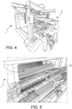
Figure 4 is a perspective view of a working station of a system for obtaining a shaded carded yarn, according to an embodiment of the invention; -
Figure 5 is a perspective view of a further working station of a system for obtaining a shaded carded yarn, according to an embodiment of the invention; -
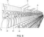
Figure 6 is a perspective view of a further working station of a system for obtaining a shaded carded yarn, according to an embodiment of the invention. - With reference to the drawings, a system for obtaining a shaded carded yarn is generally indicated by
reference numeral 1. -
System 1 is usable to perform a method for obtaining a shaded carded yarn. - The method for obtaining a shaded carded yarn comprises the following steps:
- producing, or disposing, a plurality of intimate fiber blends 2 of different type, for example, a plurality of intimate fiber blends 2 having different coloring or different fiber type, at least a first intimate fiber blend 2' and a second
intimate fiber blend 2" of which being different; - loading the plurality of intimate fiber blends 2 into
respective containment bins 3 so that eachbin 3 contains a singleintimate fiber blend 2; - unloading the first intimate fiber blend 2' from the
respective bin 3 onto abelt 4. Ifseveral bins 3 simultaneously contain respectiveintimate fiber blends 2, keeping the remaining intimate fiber blends 2 in therespective bins 3 when unloading the first intimate fiber blend 2' ontobelt 4. - transferring the first intimate fiber blend 2' from
belt 4 to acarding station 5; - determining the complete transfer of the first intimate fiber blend 2' from
belt 4 to thecarding station 5 and the absence of substantial residuals of the first intimate fiber blend 2' onbelt 4; - unloading the second
intimate fiber blend 2" from therespective bin 3 ontobelt 4. - Advantageously, a method thus configured allows conveying the different types of intimate fiber blends 2 to a
carding station 5 in a selective and controlled manner in order to then obtain a shaded carded yarn with predetermined composition and shade, controlled and adjusted with high precision. - Specifically, such a method prevents an undesired mixing between
intimate fiber blends 2 having different coloring or type before they are transferred to thecarding station 5. Indeed, such an undesired mixing would affect the resulting yarn and not allow controlling or determining the shade of the final carded yarn in advance. - Therefore, a method thus configured ensures control over the end results, allowing a carded yarn with the desired shade to be obtained with high precision.
- "Intimate fiber blend" means a set of mixed and/or tangled fibers. Specifically, the intimate fiber blends of the present invention are obtained by means of composition with very precise and well-defined percentages of fibers so as to obtain the desired intimate fiber blends having an intimate mixture of different fibers and/or colors.
- According to an embodiment,
belt 4 comprises, in sequence, aconveyor belt 21, anextractor belt 22, a hookedloading belt 23, and a hookedunloading belt 25. - The step of unloading the first intimate fiber blend 2' from the
respective bin 3 onto abelt 4 comprises the step of unloading the first intimate fiber blend 2' from therespective bin 3 onto theconveyor belt 21. - Further, the step of transferring the first intimate fiber blend 2' from
belt 4 to acarding station 5 comprises the steps of: - transporting, by the
conveyor belt 21, the first intimate fiber blend 2' to theextractor belt 22, - extracting, by the
extractor belt 22, the first intimate fiber blend 2' from theconveyor belt 21 and transferring the first intimate fiber blend 2' onto the hookedloading belt 23, - transporting, by the hooked
loading belt 23, the first intimate fiber blend 2' to the hookedunloading belt 25, - extracting, by the hooked
unloading belt 25, the first intimate fiber blend 2' from the hookedloading belt 23 and unloading the first intimate fiber blend 2' to thecarding station 5. - According to an embodiment,
belt 4 further comprises a hookedmeter belt 24. - The hooked
meter belt 24 is positioned at the hookedloading belt 23, at an end of the hookedloading belt 23 opposite to theextractor belt 22. - Further, the step of transferring the first intimate fiber blend 2' from
belt 4 to acarding station 5 comprises the step of leveling, by the hookedmeter belt 24, the thickness of the first intimate fiber blend 2' transported by the hookedloading belt 23 to the hookedunloading belt 25. - The leveling of the thickness of the first intimate fiber blend 2' is performed by rotating the
hooked meter belt 24 in the same direction as the rotation direction of the hookedloading belt 23. - Thickness means the thickness of the
intimate fiber blend 2 measured in direction transverse to the hookedloading belt 23 along which theintimate fiber blend 2 is transported. - Advantageously, such a configuration avoids transferring, to the
carding station 5, "blocks" ofintimate fiber blend 2 which are too thick and would affect the end result. - According to an embodiment, the step of extracting the first intimate fiber blend 2' from the hooked
loading belt 23 and unloading the first intimate fiber blend 2' to thecarding station 5 is performed by a rotation of the hookedunloading belt 25 in the direction opposite to the rotation direction of the hookedloading belt 23. - Thereby, the hooks of the hooked
unloading belt 25 intersect with the hooks of the hookedloading belt 23 to hook the first intimate fiber blend 2' from the hookedloading belt 23 and unload the first intimate fiber blend 2' to thecarding station 5. - Preferably, the first intimate fiber blend 2' is unloaded to a
metering device 6. - According to an embodiment, the
extractor belt 22 rotates in the same direction as theconveyor belt 21. - Further, the rotation speed of the
extractor belt 22 is from two to ten times greater than the rotation speed of theconveyor belt 21. - Preferably, the rotation speed of the
extractor belt 22 is from two to ten times greater than the rotation speed of theconveyor belt 21. - Advantageously, such a configuration ensures a controllable and monitorable transfer of the
intimate fiber blend 2 to thecarding station 5. - According to an embodiment,
system 1 comprises, in sequence, afirst photocell 26, asecond photocell 27, athird photocell 28, and afourth photocell 29. - The
first photocell 26 is positioned at an end of theconveyor belt 21 facing theextractor belt 22. - The
second photocell 27 is positioned at theextractor belt 22. - The
third photocell 28 is positioned at an end of the hookedloading belt 23 facing theextractor belt 22. - The
fourth photocell 29 is positioned at the hookedloading belt 23, above thethird photocell 28. - Further, the first, second, third and
fourth photocells intimate fiber blend 2 or residuals ofintimate fiber blend 2 on therespective belt - The step of transferring the first intimate fiber blend 2' from
belt 4 to a cardingstation 5 comprises the following steps: - when the
fourth photocell 29 detects the presence of anintimate fiber blend 2 or residuals ofintimate fiber blend 2 on thehooked loading belt 23, thehooked loading belt 23 continues rotating and transferring theintimate fiber blend 2 to the cardingstation 5, while theconveyor belt 21 is stopped; - when the
fourth photocell 29 does not detect the presence of anintimate fiber blend 2 or residuals ofintimate fiber blend 2 on thehooked loading belt 23, theconveyor belt 21 and theextractor belt 22 are actuated so as to load a furtherintimate fiber blend 2 or further residuals ofintimate fiber blend 2 onto thehooked loading belt 23 until thefourth photocell 29 again detects the presence of anintimate fiber blend 2 or residuals ofintimate fiber blend 2 on thehooked loading belt 23; - when the
first photocell 26 no longer detects the presence of anintimate fiber blend 2 or residuals ofintimate fiber blend 2 on theconveyor belt 21, theextractor belt 22 and thehooked loading belt 23 continue rotating, and optionally theconveyor belt 21 is stopped; - when the
second photocell 27 no longer detects the presence of anintimate fiber blend 2 or residuals ofintimate fiber blend 2 on theextractor belt 22, thehooked loading belt 23 continues rotating so as to complete the transfer of theintimate fiber blend 2 to the cardingstation 5; - when also the
third photocell 28 no longer detects the presence of anintimate fiber blend 2 or residuals ofintimate fiber blend 2 on thehooked loading belt 23, the substantial complete transfer of theintimate fiber blend 2 to the cardingstation 5 is determined. - Advantageously, such a configuration ensures the complete and controlled transfer of the
intimate fiber blend 2 to the cardingstation 5, thus avoiding undesired mixing with different intimate fiber blends 2. - According to an embodiment,
system 1 comprises amovable thrust wall 15. - The
movable thrust wall 15 is positioned at theconveyor belt 21 and is configured to translate in a direction parallel to theconveyor belt 21 towards theextractor belt 22, from a stroke start position to a stroke end position, and vice versa. - The stroke end position is positioned substantially at the
first photocell 26. - The step of transferring the first intimate fiber blend 2' from
belt 4 to a cardingstation 5 comprises the following steps: - when the
fourth photocell 29 detects the presence of anintimate fiber blend 2 or residuals ofintimate fiber blend 2 on thehooked loading belt 23, thehooked loading belt 23 continues rotating while theconveyor belt 21 and themovable thrust wall 15 are stopped; - when the
fourth photocell 29 does not detect the presence of anintimate fiber blend 2 or residuals ofintimate fiber blend 2 on thehooked loading belt 23, thethrust wall 15 is translated in the direction of the stroke end position and theconveyor belt 21 and theextractor belt 22 are actuated so as to load a furtherintimate fiber blend 2 or further residuals ofintimate fiber blend 2 onto thehooked loading belt 23 until thefourth photocell 29 again detects the presence of anintimate fiber blend 2 or residuals ofintimate fiber blend 2 on thehooked loading belt 23; - when the
first photocell 26 no longer detects the presence of anintimate fiber blend 2 or residuals ofintimate fiber blend 2 on theconveyor belt 21, themovable thrust wall 15 has reached the stroke end position, and theextractor belt 22 and thehooked loading belt 23 continue rotating; - when the
second photocell 27 no longer detects the presence of anintimate fiber blend 2 or residuals ofintimate fiber blend 2 on theextractor belt 22, thehooked loading belt 23 continues rotating so as to complete the transfer of theintimate fiber blend 2 to the cardingstation 5; - when also the
third photocell 28 no longer detects the presence of anintimate fiber blend 2 or residuals ofintimate fiber blend 2 on thehooked loading belt 23, the substantial complete transfer of theintimate fiber blend 2 to the cardingstation 5 is determined and themovable thrust wall 15 returns to the stroke start position, and the secondintimate fiber blend 2" is unloaded from therespective bin 3 onto theconveyor belt 21. - Advantageously, such a configuration ensures the complete and controlled transfer of the
intimate fiber blend 2 to the cardingstation 5, thus avoiding undesired mixing with different intimate fiber blends 2. - According to an embodiment, the rotation speed of the
hooked loading belt 23 is adjusted as a function of the amount ofintimate fiber blend 2 onbelt 4. - A decrease in the amount of
intimate fiber blend 2 onbelt 4 corresponds to an increase in the rotation speed of thehooked loading belt 23. - Vice versa, an increase in the amount of
intimate fiber blend 2 onbelt 4 corresponds to a decrease in the rotation speed of thehooked loading belt 23. - According to an embodiment, the rotation speed of the
hooked loading belt 23 is inversely proportional to the rotation speed of the hookedmeter belt 24. - A decrease in the amount of
intimate fiber blend 2 onbelt 4 corresponds to an increase in the rotation speed of thehooked loading belt 23 and a related decrease in the rotation speed of the hookedmeter belt 24. - Vice versa, an increase in the amount of
intimate fiber blend 2 onbelt 4 corresponds to a decrease in the rotation speed of thehooked loading belt 23 and a related increase in the rotation speed of the hookedmeter belt 24. - Advantageously, such a configuration ensures transferring the
intimate fiber blend 2 to the cardingstation 5 within the times established by the cardingstation 5 for receiving theintimate fiber blend 2, and simultaneously avoids transferring too thick anintimate fiber blend 2 to the cardingstation 5, thus avoiding the end result from being affected. - According to an embodiment,
system 1 comprises ametering device 6. - Preferably, the
metering device 6 is an electronic scale. - The
metering device 6 is configured to receive portions ofintimate fiber blend 2 from the hooked unloadingbelt 25, dose and transfer the portions ofintimate fiber blend 2 to the cardingstation 5. - The step of transferring the first intimate fiber blend 2' from
belt 4 to a cardingstation 5 comprises the steps of: - gradually depositing a plurality of portions of the first intimate fiber blend 2' on the
metering device 6 over an actual time interval so as to obtain a predefined intimate fiber blend dose 7 having a predefined weight; - transferring the predefined intimate fiber blend dose 7 from the
metering device 6 to the cardingstation 5 at the end of a cycle time interval;- where the actual time interval is less than the cycle time interval,
- and optionally:
- determining a threshold time interval, where the threshold time interval is less than the cycle time interval and greater than the actual time interval, and preferably the threshold time interval is between 50% and 99% of the cycle time,
- determining a minimum threshold time interval and a maximum threshold time interval, both less than the threshold time interval, and where the minimum threshold time interval is less than the maximum threshold time interval,
- monitoring that the actual time interval is less than the threshold time interval,
- when the actual time interval is equal to or greater than the maximum threshold time interval, the rotation speed of the
hooked loading belt 23 is increased; - vice versa, when the actual time interval is equal to or less than the minimum threshold time interval, the rotation speed of the
hooked loading belt 23 is decreased.
- Advantageously, such a configuration allows synchronizing the controlled transfer of
intimate fiber blend 2 with the cycle time determinable by the cardingstation 5, thus avoiding undesired mixing of the intimate fiber blends 2 and avoiding too much material or too thick anintimate fiber blend 2 to be transferred to the cardingstation 5, which would affect the end result. Too thick anintimate fiber blend 2 could be generated if theintimate fiber blend 2 were transferred too quickly to the cardingstation 5, i.e., with a shorter actual time than the cycle time. - According to an embodiment,
system 1 comprises at least onebarrier gate 30 interposed between the hooked unloadingbelt 25 and themetering device 6. - The step of transferring the first intimate fiber blend 2' from
belt 4 to a cardingstation 5 comprises the steps of: - keeping the
barrier gate 30 open during the actual time interval so as to allow the formation of the predefined intimate fiber blend dose 7 on themetering device 6; - closing the
barrier gate 30 upon the completion of the formation of the predefined intimate fiber blend dose 7, at the end of the actual time interval, so as to prevent further residuals ofintimate fiber blend 2 from depositing on themetering device 6, - preferably transferring the predefined intimate fiber blend dose 7 contained in the
metering device 6 to the cardingstation 5 by opening anopenable bottom 14 of themetering device 6. - According to an embodiment, the step of loading the plurality of intimate fiber blends 2 into
respective containment bins 3 so that eachbin 3 contains a singleintimate fiber blend 2 comprises providing apneumatic supply system 8, comprising asupply duct 9 connected to acarriage 10 and a pneumatic pumping system comprising afan 13 and acyclone 16. -
Cyclone 16 is interposed betweenbin 3 andfan 13 and is configured to slow down theintimate fiber blend 2 conveyed byfan 13 and expel excess air conveyed byfan 13. - Further, the pneumatic pumping system is configured to convey a pneumatic flow into the
supply duct 9. - The method further comprises:
- translating the
supply duct 9, bycarriage 10, to a givenbin 3 intended to receive the relatedintimate fiber blend 2; - inserting the related
intimate fiber blend 2 into thesupply duct 9 so as to convey theintimate fiber blend 2 intocyclone 16 and then loading the relatedintimate fiber blend 2 into therespective bin 3 by means of a pneumatic flow conveyed byfan 13 of the pneumatic pumping system. - According to an embodiment, the method comprises:
- determining, by a sensor system, preferably optical sensors, the complete emptying of a given
bin 3 to be loaded with a newintimate fiber blend 2; - loading the new
intimate fiber blend 2 into theempty bin 3. - According to an embodiment, the method comprises determining, by the
electronic processing unit 11, the givenintimate fiber blend 2 to be loaded into therespective bin 3 based on a programmable loading sequence determined by theelectronic processing unit 11. - According to an embodiment, the step of unloading the
intimate fiber blend 2 from therespective bin 3 ontobelt 4 comprises determining, by anelectronic processing unit 11 ofsystem 1, the givenintimate fiber blend 2 to be unloaded based on a programmable unloading sequence determined by theelectronic processing unit 11. - According to an embodiment, the step of unloading the
intimate fiber blend 2 from therespective bin 3 ontobelt 4 comprises: - providing
bins 3 comprising anopenable bottom gate 12 and a pneumatic pumping system, respectively; - opening the
bottom gate 12 of therespective bin 3 containing the respectiveintimate fiber blend 2 to be unloaded and pumping a pressurized air flow into the givenbin 3, in a direction exiting thebottom gate 12 so as to unload theintimate fiber blend 2 exiting frombin 3;
and optionally, - detecting the complete emptying of
bin 3 by means of a sensor system, preferably optical sensors,
and optionally, - providing a
suction hopper 31 and sucking air fromsystem 1 so as to decrease the turbulence generated by the unloading of theintimate fiber blend 2 frombin 3 tobelt 4. - According to an embodiment, following the step of transferring the first intimate fiber blend 2' from
belt 4 to a cardingstation 5, the method comprises the step of: - carding, in a carding
station 5, the one or more intimate fiber blends 2 transferred to the cardingstation 5 so as to obtain a shaded carded web; - in a cutting
station 17, cutting the shaded carded web so as to obtain a plurality ofrovings 19 of shaded carded thread; - in a
spinning frame 18, spinning the thread of the shaded cardedrovings 19, preferably by drawing or twisting the thread, so as to obtain a shaded cardedyarn 20; detecting, preferably by vibration sensors, the possible breakage ofyarn 20 and temporarily stopping the spinning upon the possible breakage of the shadedyarn 20; - optionally, in a winding station, winding the shaded carded
yarn 20 so as to obtain a plurality of perfectly identical spools of shaded carded yarn. - According to an embodiment, the step of spinning the thread of the shaded carded
rovings 19 comprises the step of: - detecting, by preferably optical sensors, the possible breakage of roving 19 or shaded carded
yarn 20 and stopping the spinning of roving 19 at the possible breakage of the roving or shaded cardedyarn 20;
and/or - monitoring and adjusting, by the
electronic processing unit 11, the carding of the one or more different intimate fiber blends 2 so as to even the thickness of the shaded carded web produced by the cardingstation 5;
and/or - after the carding, cleaning the carding
station 5 of any residuals of intimate fiber blends 2, preferably by means of compressed air cleaners or blowers. - Naturally, the preceding production steps described with reference to the first intimate fiber blend 2' are also applicable to the second
intimate fiber blend 2" processed after the first intimate fiber blend 2', and to possible further intimate fiber blends 2 processed after the first and second intimate fiber blends 2', 2". - According to a further aspect of the invention, a
system 1 for obtaining a shaded carded yarn comprises a plurality ofcontainment bins 3 configured to contain a respectiveintimate fiber blend 2. -
System 1 comprises abelt 4 configured to receive the intimate fiber blends 2 unloaded from therespective bins 3. -
System 1 comprises a cardingstation 5 positioned downstream ofbelt 4 and configured to receive the intimate fiber blends 2 frombelt 4. -
System 1 comprises means for determining the complete transfer of the first intimate fiber blend 2' frombelt 4 to the cardingstation 5 and the absence of substantial residuals of the first intimate fiber blend 2' onbelt 4. - Advantageously, a
system 1 thus configured allows sending the different types of intimate fiber blends 2 to a cardingstation 5 in a selective and controlled manner in order to then obtain a shaded carded yarn with predetermined composition and shade, controlled and adjusted with high precision. - Specifically, such a
system 1 is configured to prevent an undesired mixing between intimate fiber blends 2 having different coloring or type before they are transferred to the cardingstation 5. Indeed, such an undesired mixing would affect the resulting yarn and not allow controlling or determining the shade of the final carded yarn in advance. - Therefore, a
system 1 thus configured ensures the control over the end result, allowing a carded yarn with the desired shade to be obtained with high precision. - According to an embodiment,
belt 4 comprises, in sequence, aconveyor belt 21, anextractor belt 22, ahooked loading belt 23, and ahooked unloading belt 25. - Further,
system 1 is configured to unload the first intimate fiber blend 2' from therespective bin 3 onto theconveyor belt 21. - The
extractor belt 21 is configured to transport the first intimate fiber blend 2' to theextractor belt 22. - The
extractor belt 22 is configured to extract the first intimate fiber blend 2' from theconveyor belt 21 and transfer the first intimate fiber blend 2' onto thehooked loading belt 23. - The
hooked loading belt 23 is configured to the first intimate fiber blend 2' to the hooked unloadingbelt 25. - The hooked unloading
belt 25 is configured to extract the first intimate fiber blend 2' from the hookedloading belt 23 and unload the first intimate fiber blend 2' to the cardingstation 5. - According to an embodiment,
belt 4 further comprises ahooked meter belt 24 positioned at thehooked loading belt 23, at an end of thehooked loading belt 23 opposite to theextractor belt 22. - The
hooked meter belt 24 is configured to level the thickness of the first intimate fiber blend 2' transported by the hookedloading belt 23 to the hooked unloadingbelt 25. - According to an embodiment, the hooked unloading
belt 25 is configured to rotate in a direction opposite to the rotation direction of thehooked loading belt 23. Therefore, if the hooked unloadingbelt 25 rotates in a counter-clockwise direction, thehooked loading belt 23 rotates in a clockwise direction, and vice versa. Therefore, according to such a configuration, the hooks of the mutually facinghooked loading 23 and unloading 25 belt are directed in a same tangential direction. - Preferably, the hooked unloading
belt 25 is configured to rotate at a greater speed than the hookedloading belt 23. Advantageously, this facilitates the extraction ofintimate fiber blend 2 from the hookedloading belt 23 and the unloading to the cardingstation 5. - According to an embodiment, the
hooked loading belt 23 and the hooked unloadingbelt 25 are positioned with respect to each other and configured so that the hooks of the hooked unloadingbelt 25 intersect with the hooks of thehooked loading belt 23. Advantageously, this facilitates the action of hooking the first intimate fiber blend 2' by the hookedloading belt 23 and unloading the first intimate fiber blend 2' to the cardingstation 5, preferably to ametering device 6. - According to an embodiment, the
extractor belt 22 is configured to rotate in the same direction as theconveyor belt 21. Therefore, if theconveyor belt 21 rotates in counter-clockwise direction, also theextractor belt 22 rotates in counter-clockwise direction, and vice versa. Therefore, according to such a configuration, the surfaces of the mutually facingconveyor belt 21 and theextractor belt 22 are directed in two opposite tangential directions. - According to an embodiment, the
extractor belt 22 is configured to rotate at a speed from two to five times greater than the rotation speed of theconveyor belt 21. Preferably, theextractor belt 22 is configured to rotate at a speed from two to three times greater than the rotation speed of theconveyor belt 21. - According to an embodiment,
system 1 comprises, in sequence, afirst photocell 26, asecond photocell 27, athird photocell 28, and afourth photocell 29, where: - the
first photocell 26 is positioned at an end of theconveyor belt 21 facing theextractor belt 22, - the
second photocell 27 is positioned at theextractor belt 22, - the
third photocell 28 is positioned at an end of thehooked loading belt 23 facing theextractor belt 22, - the
fourth photocell 29 is positioned at thehooked loading belt 23, above thethird photocell 28, and optionally thefourth photocell 29 is movable in height with respect to thethird photocell 28. - The first, second, third and
fourth photocells intimate fiber blend 2 or residuals ofintimate fiber blend 2 on therespective belt - The
conveyor belt 21, theextractor belt 22, thehooked loading belt 23, and the hooked unloadingbelt 25 are configured to be selectively movable depending on the detection of the presence or absence of anintimate fiber blend 2 or residuals ofintimate fiber blend 2 by the first and/or second and/or third and/orfourth photocells - According to an embodiment,
system 1 comprises amovable thrust wall 15 positioned at theconveyor belt 21 and configured to translate in a direction parallel to theconveyor belt 21 towards theextractor belt 22, from a stroke start position to a stroke end position, and vice versa. - The stroke end position is positioned substantially at the
first photocell 26. - The
movable thrust wall 15 is configured to be selectively movable depending on the detection of the presence or absence of anintimate fiber blend 2 or residuals ofintimate fiber blend 2 by the first and/or second and/or third and/orfourth photocells - According to an embodiment,
system 1 comprises a cardingstation 5, positioned downstream ofbelt 4 with reference to the forward direction ofbelt 4, configured to card the one or more intimate fiber blends 2 transferred to the cardingstation 5 so as to obtain a shaded carded web. - Further,
system 1 comprises a cuttingstation 17 configured to cut the shaded carded web so as to obtain a plurality ofrovings 19 of shaded carded thread. - Further,
system 1 comprises aspinning frame 18 configured to spin the thread of the shaded cardedrovings 19, preferably by drawing or twisting the thread, so as to obtain a shaded cardedyarn 20. - According to an embodiment,
system 1 comprises a winding station configured to wind the shaded cardedyarn 20 so as to obtain a plurality of spools of shaded carded yarn. - According to an embodiment,
system 1 comprises sensors, preferably optical sensors, configured to detect the possible breakage of the roving or shaded cardedyarn 20, and locking means configured to stop the spinning of therovings 19 at the possible breakage of the roving or shaded cardedyarn 20 detected by the sensors. - According to an embodiment,
system 1 comprises compressed air cleaners or blowers configured to clean the cardingstation 5 of any residuals of intimate fiber blends 2 after carding. - Advantageously, this avoids a possible and undesired mixing of residuals of
intimate fiber blend 2 with different intimate fiber blends 2 then processed by the cardingstation 5, which would negatively affect the end result. - According to an embodiment,
system 1 comprises anelectronic processing unit 11. - The
electronic processing unit 11 is configured to controlsystem 1. - According to an embodiment, the
electronic processing unit 11 is configured to monitor and adjust the carding of the one or more different intimate fiber blends 2 so as to even the thickness of the shaded carded web produced by the cardingstation 5. - According to an embodiment, the
electronic processing unit 11 is configured to determine the givenintimate fiber blend 2 to be unloaded based on an unloading sequence. - According to an embodiment, the
electronic processing unit 11 is configured to load the given intimate fiber blends into therespective bins 3 based on a programmable loading sequence. - According to an embodiment, the method comprises monitoring and adjusting, by means of the
electronic processing unit 11, the carding of the one or more different intimate fiber blends 2 so as to even the thickness of the shaded carded web produced by the cardingstation 5. - Advantageously, the method and the
system 1 thus configured allow obtaining a shaded carded yarn, the composition and shade of which are predetermined, controlled, and adjusted with high precision. - Further advantageously, the method and the
system 1 thus configured allow precisely adjusting and automating the production process of a shaded carded yarn. - Further advantageously, the method and the
system 1 thus configured allow avoiding mixing types of intimate fiber blends 2, thus ensuring the precision of the end result. - In particular, the method and the
system 1 thus configured allow effectively avoiding the presence of residuals ofintimate fiber blend 2 which would otherwise get mixed with a subsequentintimate fiber blend 2 unloaded ontobelt 4, which would affect the end result. - Further advantageously, the method and the
system 1 thus configured allow supplying the cardingstation 5 with uniform intimate fiber blend doses, thus ensuring the production, by the cardingstation 5, of a uniform shaded carded web having a predetermined thickness, thus avoiding deformities in the creation of the shaded carded web. - Further advantageously, the method and the
system 1 thus configured allow automating the in-line adjustment of the thickness of the shaded carded web produced by the cardingstation 5. - Further advantageously, the method and the
system 1 thus configured allow ensuring the complete emptying ofbin 3, avoiding possible undesired blending of residuals of theintimate fiber blend 2 with different intimate fiber blends 2 then loaded intobin 3, which would negatively affect the end result. - Further advantageously, the method and the
system 1 thus configured allow loading the plurality of intimate fiber blends 2 into therespective bins 3 in an easy, quick manner and without damage. - Obviously, those skilled in the art will be able to make changes or adaptations to the present invention, without however departing from the scope of the following claims.
-
- 1. System
- 2. Intimate fiber blends
- 2'. First intimate fiber blend
- 2". Second intimate fiber blend
- 3. Containment bin
- 4. Belt
- 5. Carding station
- 6. Metering device
- 7. Predefined intimate fiber blend dose
- 8. Pneumatic supply system
- 9. Supply duct
- 10. Carriage
- 11. Electronic processing unit
- 12. Bottom gate
- 13. Fan
- 14. Openable bottom
- 15. Movable thrust wall
- 16. Cyclone
- 17. Cutting station
- 18. Spinning frame
- 19. Rovings
- 20. Shaded carded yarn
- 21. Conveyor belt
- 22. Extractor belt
- 23. Hooked loading belt
- 24. Hooked meter belt
- 25. Hooked unloading belt
- 26. First photocell
- 27. Second photocell
- 28. Third photocell
- 29. Fourth photocell
- 30. Barrier gate
- 31. Suction hopper
Claims (15)
- A method for obtaining a shaded carded yarn by means of a system (1) for obtaining a shaded carded yarn, comprising the following steps:- producing, or disposing, a plurality of intimate fiber blends (2) of different type, for example a plurality of intimate fiber blends (2) having different coloring or different fiber type, at least a first intimate fiber blend (2') and a second intimate fiber blend (2") of which being different;- loading the plurality of intimate fiber blends (2) into respective containment bins (3) so that each bin (3) contains a single intimate fiber blend (2);- unloading the first intimate fiber blend (2') from the respective bin (3) onto a belt (4);- transferring the first intimate fiber blend (2') from the belt (4) to a carding station (5);- determining the complete transfer of the first intimate fiber blend (2') from the belt (4) to the carding station (5) and the absence of residuals of the first intimate fiber blend (2') on the belt (4);- unloading the second intimate fiber blend (2") from the respective bin (3) onto the belt (4),wherein following the step of transferring the first intimate fiber blend (2') from the belt (4) to a carding station (5), the method comprises the step of:- carding, in a carding station (5), the one or more intimate fiber blends (2) transferred to the carding station (5) so as to obtain a shaded carded web;- in a cutting station (17), cutting the shaded carded web so as to obtain a plurality of rovings (19) of shaded carded thread;- in a spinning frame (18), spinning the thread of the shaded carded rovings (19), preferably by drawing or twisting the thread, so as to obtain a shaded carded yarn (20);- optionally, in a winding station, winding the shaded carded yarn (20) so as to obtain a plurality of spools of shaded carded yarn.
- A method according to claim 1, wherein the belt (4) comprises, in sequence, a conveyor belt (21), an extractor belt (22), a hooked loading belt (23), and a hooked unloading belt (25),wherein the step of unloading the first intimate fiber blend (2') from the respective bin (3) onto the belt (4) comprises the step of:- unloading the first intimate fiber blend (2') from the respective bin (3) onto the conveyor belt (21),and wherein the step of transferring the first intimate fiber blend (2') from the belt (4) to the carding station (5) comprises the steps of:- transporting, by the conveyor belt (21), the first intimate fiber blend (2') to the extractor belt (22),- extracting, by the extractor belt (22), the first intimate fiber blend (2') from the conveyor belt (21) and transferring the first intimate fiber blend (2') onto the hooked loading belt (23),- transporting, by the hooked loading belt (23), the first intimate fiber blend (2') to the hooked unloading belt (25),- extracting, by the hooked unloading belt (25), the first intimate fiber blend (2') from the hooked loading belt (23) and unloading the first intimate fiber blend (2') to the carding station (5).
- A method according to claim 2, wherein the belt (4) further comprises a hooked meter belt (24) positioned at the hooked loading belt (23), at an end of the hooked loading belt (23) opposite to the extractor belt (22),
wherein the step of transferring the first intimate fiber blend (2') from the belt (4) to the carding station (5) comprises the step of:- leveling, by the hooked meter belt (24), the thickness of the first intimate fiber blend (2') transported by the hooked loading belt (23) to the hooked unloading belt (25). - A method according to claim 2, wherein the system (1) comprises, in sequence, a first photocell (26), a second photocell (27), a third photocell (28), and a fourth photocell (29), wherein:- the first photocell (26) is positioned at an end of the conveyor belt (21) facing the extractor belt (22),- the second photocell (27) is positioned at the extractor belt (22),- the third photocell (28) is positioned at an end of the hooked loading belt (23) facing the extractor belt (22),- the fourth photocell (29) is positioned at the hooked loading belt (23), above the third photocell (28),wherein the first, second, third and fourth photocells (26, 27, 28, 29) are configured to detect the presence or absence of an intimate fiber blend (2) or residuals of intimate fiber blend (2) on the respective belt (21, 22, 23, 25) at which they are positioned,and wherein the step of transferring the first intimate fiber blend (2') from the belt (4) to the carding station (5) comprises the following steps:- when the fourth photocell (29) detects the presence of an intimate fiber blend (2) or residuals of intimate fiber blend (2) on the hooked loading belt (23), the hooked loading belt (23) continues rotating and transferring the intimate fiber blend (2) to the carding station (5), while the conveyor belt (21) is stopped;- when the fourth photocell (29) does not detect the presence of an intimate fiber blend (2) or residuals of intimate fiber blend (2) on the hooked loading belt (23), the conveyor belt (21) and the extractor belt (22) are actuated so as to load a further intimate fiber blend (2) or further residuals of intimate fiber blend (2) onto the hooked loading belt (23) until the fourth photocell (29) again detects the presence of an intimate fiber blend (2) or residuals of intimate fiber blend (2) on the hooked loading belt (23);- when the first photocell (26) no longer detects the presence of an intimate fiber blend (2) or residuals of intimate fiber blend (2) on the conveyor belt (21), the extractor belt (22) and the hooked loading belt (23) continue rotating, and optionally the conveyor belt (21) is stopped;- when the second photocell (27) no longer detects the presence of an intimate fiber blend (2) or residuals of intimate fiber blend (2) on the extractor belt (22), the hooked loading belt (23) continues rotating so as to complete the transfer of the intimate fiber blend (2) to the carding station (5), and optionally the extractor belt (22) is stopped;- when also the third photocell (28) no longer detects the presence of an intimate fiber blend (2) or residuals of intimate fiber blend (2) on the hooked loading belt (23), the substantial complete transfer of the intimate fiber blend (2) to the carding station (5) is determined and another cycle begins.
- A method according to claim 4, wherein the system (1) comprises a movable thrust wall (15) positioned at the conveyor belt (21) and configured to translate in a direction parallel to the conveyor belt (21) towards the extractor belt (22), from a stroke start position to a stroke end position, and vice versa, wherein the stroke end position is positioned substantially at the first photocell (26),
wherein the step of transferring the first intimate fiber blend (2') from the belt (4) to the carding station (5) comprises the following steps:- when the fourth photocell (29) detects the presence of an intimate fiber blend (2) or residuals of intimate fiber blend (2) on the hooked loading belt (23), the hooked loading belt (23) continues rotating while the conveyor belt (21) and the movable thrust wall (15) are stopped;- when the fourth photocell (29) does not detect the presence of an intimate fiber blend (2) or residuals of intimate fiber blend (2) on the hooked loading belt (23), the thrust wall (15) is translated in the direction of the stroke end position and the conveyor belt (21) and the extractor belt (22) are actuated so as to load a further intimate fiber blend (2) or further residuals of intimate fiber blend (2) onto the hooked loading belt (23) until the fourth photocell (29) again detects the presence of an intimate fiber blend (2) or residuals of intimate fiber blend (2) on the hooked loading belt (23);- when the first photocell (26) no longer detects the presence of an intimate fiber blend (2) or residuals of intimate fiber blend (2) on the conveyor belt (21), the movable thrust wall (15) has reached the stroke end position, and the extractor belt (22) and the hooked loading belt (23) continue rotating;- when the second photocell (27) no longer detects the presence of an intimate fiber blend (2) or residuals of intimate fiber blend (2) on the extractor belt (22), the hooked loading belt (23) continues rotating so as to complete the transfer of the intimate fiber blend (2) to the carding station (5);- when also the third photocell (28) no longer detects the presence of an intimate fiber blend (2) or residuals of intimate fiber blend (2) on the hooked loading belt (23), the substantial complete transfer of the intimate fiber blend (2) to the carding station (5) is determined and the movable thrust wall (15) returns to the stroke start position, and the second intimate fiber blend (2") is unloaded from the respective bin (3) onto the conveyor belt (21). - A method according to claim 3, wherein the rotation speed of the hooked loading belt (23) is adjusted as a function of the amount of intimate fiber blend (2) on the belt (4), and wherein a decrease in the amount of intimate fiber blend (2) on the belt (4) corresponds to an increase in the rotation speed of the hooked loading belt (23), and vice versa, an increase in the amount of intimate fiber blend (2) on the belt (4) corresponds to a decrease in the rotation speed of the hooked loading belt (23),
and/or wherein the rotation speed of the hooked loading belt (23) is inversely proportional to the rotation speed of the hooked meter belt (24), and wherein a decrease in the amount of intimate fiber blend (2) on the belt (4) corresponds to an increase in the rotation speed of the hooked loading belt (23) and a related decrease in the rotation speed of the hooked meter belt (24), and vice versa, an increase in the amount of intimate fiber blend (2) on the belt (4) corresponds to a decrease in the rotation speed of the hooked loading belt (23) and a related increase in the rotation speed of the hooked meter belt (24). - A method according to claim 2, wherein the system (1) comprises a metering device (6), preferably an electronic scale, configured to receive portions of intimate fiber blend (2) from the hooked unloading belt (25), meter and transfer the portions of intimate fiber blend (2) to the carding station (5),wherein the step of transferring the first intimate fiber blend (2') from the belt (4) to a carding station (5) comprises the steps of:- gradually depositing a plurality of portions of the first intimate fiber blend (2') on the metering device (6) over an actual time interval so as to obtain a predefined intimate fiber blend dose (7) having a predefined weight;- transferring the predefined intimate fiber blend dose (7) from the metering device (6) to the carding station (5) at the end of a cycle time interval;where the actual time interval is less than the cycle time interval,and optionally:- determining a threshold time interval, where the threshold time interval is less than the cycle time interval and greater than the actual time interval, and preferably the threshold time interval is between 50% and 99% of the cycle time,- determining a minimum threshold time interval and a maximum threshold time interval, both less than the threshold time interval, and where the minimum threshold time interval is less than the maximum threshold time interval,- monitoring that the actual time interval is less than the threshold time interval,- when the actual time interval is equal to or greater than the maximum threshold time interval, the rotation speed of the hooked loading belt (23) is increased;- vice versa, when the actual time interval is equal to or less than the minimum threshold time interval, the rotation speed of the hooked loading belt (23) is decreased.
- A method according to claim 7, wherein the system (1) comprises at least one barrier gate (30) interposed between the hooked unloading belt (25) and the metering device (6),
wherein the step of transferring the first intimate fiber blend (2') from the belt (4) to a carding station (5) comprises the steps of:- keeping the barrier gate (30) open during the actual time interval so as to allow the formation of the predefined intimate fiber blend dose (7) on the metering device (6);- closing the barrier gate (30) upon the completion of the formation of the predefined intimate fiber blend dose (7), at the end of the actual time interval, so as to prevent further residuals of intimate fiber blend (2) from depositing on the metering device (6),- preferably transferring the predefined intimate fiber blend dose (7) contained in the metering device (6) to the carding station (5) by opening an openable bottom (14) of the metering device (6) at the end of the cycle time interval. - A method according to any one of the preceding claims, wherein the step of loading the plurality of intimate fiber blends (2) into respective containment bins (3) so that each bin (3) contains a single intimate fiber blend (2), comprises:- providing a pneumatic supply system (8), comprising a supply duct (9) connected to a carriage (10) and a pneumatic pumping system comprising a fan (13) and a cyclone (16), wherein the cyclone (16) is interposed between the bin (3) and the fan (13) and is configured to slow down the intimate fiber blend (2) conveyed by the fan (13) and expel excess air conveyed by the fan (13),
wherein the pneumatic pumping system is configured to convey a pneumatic flow into the supply duct (9);- translating the supply duct (9), by the carriage (10), to a given bin (3) intended to receive the related intimate fiber blend (2);- inserting the related intimate fiber blend (2) into the supply duct (9) so as to convey the intimate fiber blend (2) into the cyclone (16) and then loading the related intimate fiber blend (2) into the respective bin (3) by means of a pneumatic flow conveyed by the fan (13) of the pneumatic pumping system,
and/or- determining, by a sensor system, preferably optical sensors, the complete emptying of a given bin (3) to be loaded with a new intimate fiber blend (2);- loading the new intimate fiber blend (2) into the empty bin (3),
and/or- determining, by an electronic processing unit (11), the given intimate fiber blend (2) to be loaded into the respective bin (3) based on a programmable loading sequence determined by the electronic processing unit (11). - A method according to any one of the preceding claims, wherein the step of unloading the intimate fiber blend (2) from the respective bin (3) onto the belt (4) comprises:- determining, by the electronic processing unit (11) of the system (1), the given intimate fiber blend (2) to be unloaded based on a programmable unloading sequence determined by the electronic processing unit (11),
and/or- providing bins (3) comprising an openable bottom gate (12) and a pneumatic pumping system, respectively;- opening the bottom gate (12) of the respective bin (3) containing the respective intimate fiber blend (2) to be unloaded and pumping a pressurized air flow into the given bin (3), in a direction exiting the bottom gate (12) so as to unload the intimate fiber blend (2) exiting from the bin (3);
and optionally,- detecting the complete emptying of the bin (3) by means of a sensor system, preferably optical sensors,
and optionally,- providing a suction hopper (31) and sucking air from the system (1) so as to decrease the turbulence generated by unloading the intimate fiber blend (2) from the bin (3) to the belt (4). - A method according to any one of the preceding claims, wherein the step of spinning the thread of the shaded carded rovings (19) comprises the step of:- detecting, by preferably optical sensors, the possible breakage of the roving (19) or shaded carded yarn (20) and stopping the spinning of the roving (19) at the possible breakage of the roving or shaded carded yarn (20);
and/or- monitoring and adjusting, by the electronic processing unit (11), the carding of the one or more different intimate fiber blends (2) so as to even the thickness of the shaded carded web produced by the carding station (5);
and/or- after the carding, cleaning the carding station (5) of any residuals of intimate fiber blends (2), preferably by means of compressed air cleaners or blowers. - A system (1) for obtaining a shaded carded yarn, comprising:- a plurality of containment bins (3) configured to contain a respective intimate fiber blend (2);- a belt (4) configured to receive the intimate fiber blends (2) unloaded from the respective bins (3);- a carding station (5) positioned downstream of the belt (4) and configured to receive the intimate fiber blends (2) from the belt (4), wherein the carding station (5) is configured to card the one or more intimate fiber blends (2) transferred to the carding station (5) so as to obtain a shaded carded web;- means for determining the complete transfer of the first intimate fiber blend (2') from the belt (4) to the carding station (5) and the absence of residuals of the first intimate fiber blend (2') on the belt (4);- a cutting station (17) configured to cut the shaded carded web so as to obtain a plurality of rovings (19) of shaded carded thread;- a spinning frame (18) configured to spin the thread of the shaded carded rovings (19), preferably by drawing or twisting the thread, so as to obtain a shaded carded yarn (20);- optionally, a winding station configured to wind the shaded carded yarn (20) so as to obtain a plurality of spools of shaded carded yarn.
- A system (1) according to claim 12, wherein the belt (4) comprises, in sequence, a conveyor belt (21), an extractor belt (22), a hooked loading belt (23), and a hooked unloading belt (25),wherein the system (1) is configured to unload the first intimate fiber blend (2') from the respective bin (3) onto the conveyor belt (21),wherein the extractor belt (21) is configured to transport the first intimate fiber blend (2') to the extractor belt (22),wherein the extractor belt (22) is configured to extract the first intimate fiber blend (2') from the conveyor belt (21) and transfer the first intimate fiber blend (2') onto the hooked loading belt (23),wherein the hooked loading belt (23) is configured to the first intimate fiber blend (2') to the hooked unloading belt (25),wherein the hooked unloading belt (25) is configured to extract the first intimate fiber blend (2') from the hooked loading belt (23) and unload the first intimate fiber blend (2') to the carding station (5).
- A system (1) according to claim 13, wherein the belt (4) further comprises a hooked meter belt (24) positioned at the hooked loading belt (23), at an end of the hooked loading belt (23) opposite to the extractor belt (22),and wherein the hooked meter belt (24) is configured to level the thickness of the first intimate fiber blend (2') transported by the hooked loading belt (23) to the hooked unloading belt (25),and wherein preferably the hooked unloading belt (25) is configured to rotate in a direction opposite to the rotation direction of the hooked loading belt (23),and/or to rotate at a greater speed than the hooked loading belt (23),and/or wherein the hooked loading belt (23) and the hooked unloading belt (25) are positioned with respect to each other and configured so that the hooks of the hooked unloading belt (25) intersect with the hooks of the hooked loading belt (23),and/or wherein the extractor belt (22) is configured to rotate in the same direction as the conveyor belt (21),and/or wherein the extractor belt (22) is configured to rotate at a speed from two to five times greater than the rotation speed of the conveyor belt (21).
- A system (1) according to claim 13 comprising, in sequence, a first photocell (26), a second photocell (27), a third photocell (28), and a fourth photocell (29), wherein:- the first photocell (26) is positioned at an end of the conveyor belt (21) facing the extractor belt (22),- the second photocell (27) is positioned at the extractor belt (22),- the third photocell (28) is positioned at an end of the hooked loading belt (23) facing the extractor belt (22),- the fourth photocell (29) is positioned at the hooked loading belt (23), above the third photocell (28), and optionally the fourth photocell (29) is movable in height with respect to the third photocell (28),wherein the first, second, third and fourth photocells (26, 27, 28, 29) are configured to detect the presence or absence of an intimate fiber blend (2) or residuals of intimate fiber blend (2) on the respective belt (21, 22, 23, 25) at which they are positioned,and wherein the conveyor belt (21), the extractor belt (22), the hooked loading belt (23), and the hooked unloading belt (25) are configured to be selectively movable depending on the detection of the presence or absence of an intimate fiber blend (2) or residuals of intimate fiber blend (2) by the first and/or second and/or third and/or fourth photocells (26, 27, 28, 29),and optionally comprising a movable thrust wall (15) positioned at the conveyor belt (21) and configured to translate in a direction parallel to the conveyor belt (21) towards the extractor belt (22), from a stroke start position to a stroke end position, and vice versa, wherein the stroke end position is positioned substantially at the first photocell (26),and wherein the movable thrust wall (15) is configured to be selectively movable depending on the detection of the presence or absence of an intimate fiber blend (2) or residuals of intimate fiber blend (2) by the first and/or second and/or third and/or fourth photocells (26, 27, 28, 29),and optionally comprising:- preferably optical sensors configured to detect the possible breakage of the roving or shaded carded yarn (20), and locking means configured to stop the spinning of the rovings (19) upon the possible breakage of the roving or shaded carded yarn (20) detected by the sensors;
and/or- compressed air cleaners or blowers configured to clean the carding station (5) of any residuals of intimate fiber blends (2) after carding;and/or wherein an electronic processing unit (11) is configured to monitor and adjust the carding of the one or more different intimate fiber blends (2) so as to even the thickness of the shaded carded web produced by the carding station (5).
Applications Claiming Priority (1)
| Application Number | Priority Date | Filing Date | Title |
|---|---|---|---|
| IT102023000009438A IT202300009438A1 (en) | 2023-05-11 | 2023-05-11 | SYSTEM AND METHOD FOR THE CREATION OF A SHADED CARDED YARN |
Publications (3)
| Publication Number | Publication Date |
|---|---|
| EP4461853A1 true EP4461853A1 (en) | 2024-11-13 |
| EP4461853B1 EP4461853B1 (en) | 2026-02-11 |
| EP4461853C0 EP4461853C0 (en) | 2026-02-11 |
Family
ID=87514327
Family Applications (1)
| Application Number | Title | Priority Date | Filing Date |
|---|---|---|---|
| EP24174888.8A Active EP4461853B1 (en) | 2023-05-11 | 2024-05-08 | System and method for the production of a shaded carded yarn |
Country Status (3)
| Country | Link |
|---|---|
| EP (1) | EP4461853B1 (en) |
| ES (1) | ES3064370T3 (en) |
| IT (1) | IT202300009438A1 (en) |
Citations (3)
| Publication number | Priority date | Publication date | Assignee | Title |
|---|---|---|---|---|
| JPS4836424A (en) * | 1971-09-10 | 1973-05-29 | ||
| DE9116319U1 (en) * | 1991-06-12 | 1992-08-20 | Trützschler GmbH & Co KG, 4050 Mönchengladbach | Device for removing and mixing textile fibres, e.g. cotton, chemical fibres, etc. |
| FR2874625A1 (en) * | 2004-08-31 | 2006-03-03 | Truetzschler & Co | APPARATUS FOR IMPLEMENTING A FIBROUS FEEDING DEVICE, FOR EXAMPLE A HOPPER SUPPLY DEVICE |
-
2023
- 2023-05-11 IT IT102023000009438A patent/IT202300009438A1/en unknown
-
2024
- 2024-05-08 EP EP24174888.8A patent/EP4461853B1/en active Active
- 2024-05-08 ES ES24174888T patent/ES3064370T3/en active Active
Patent Citations (3)
| Publication number | Priority date | Publication date | Assignee | Title |
|---|---|---|---|---|
| JPS4836424A (en) * | 1971-09-10 | 1973-05-29 | ||
| DE9116319U1 (en) * | 1991-06-12 | 1992-08-20 | Trützschler GmbH & Co KG, 4050 Mönchengladbach | Device for removing and mixing textile fibres, e.g. cotton, chemical fibres, etc. |
| FR2874625A1 (en) * | 2004-08-31 | 2006-03-03 | Truetzschler & Co | APPARATUS FOR IMPLEMENTING A FIBROUS FEEDING DEVICE, FOR EXAMPLE A HOPPER SUPPLY DEVICE |
Also Published As
| Publication number | Publication date |
|---|---|
| EP4461853B1 (en) | 2026-02-11 |
| IT202300009438A1 (en) | 2024-11-11 |
| EP4461853C0 (en) | 2026-02-11 |
| ES3064370T3 (en) | 2026-04-24 |
Similar Documents
| Publication | Publication Date | Title |
|---|---|---|
| US5025533A (en) | Method of blending textile fibers | |
| US7926147B2 (en) | Apparatus for the fibre-sorting or fibre-selection of a fibre bundle comprising textile fibres, especially for combing | |
| US4779311A (en) | Method and apparatus for feeding a plurality of textile fiber processing machines | |
| CN104379822B (en) | Method and device for adjusting fiber feed to carding machine | |
| US7752715B2 (en) | Procedure and system for opening and proportioning synthetic material | |
| GB2175927A (en) | Method and apparatus for taking-off flocks from fibre bales | |
| JP4739830B2 (en) | A device for measuring the mass of fiber material passing through a spinning pre-processor or system. | |
| US4864693A (en) | Flow-through fiber preparation feed system and method | |
| US4587691A (en) | Method and apparatus for feeding fiber material to a plurality of fiber processing machines | |
| EP4461853B1 (en) | System and method for the production of a shaded carded yarn | |
| US4701981A (en) | Apparatus for pneumatically feeding a plurality of carding machines | |
| US7370391B2 (en) | Device on a spinning preparation machine, for example a tuft feeder, having a feed device | |
| US20020152583A1 (en) | Method and apparatus for fiber length measurement | |
| US3029477A (en) | Automatic carding plant | |
| CN109023599A (en) | Production control in blowing room | |
| US6442803B1 (en) | Method of producing blends of cotton lint | |
| US5218741A (en) | Textile fiber mixer | |
| US5329668A (en) | Method and apparatus for detaching and mixing fiber tufts | |
| US4399590A (en) | Method and apparatus for checking a blending plant for textile staple fibres | |
| CZ20012004A3 (en) | Method of mixing fibrous components, weighing feeding device and control device for controlling feeding rate of material supply | |
| US5143485A (en) | Transport air control | |
| US7075018B1 (en) | Mixing fibrous constituents | |
| CN212451794U (en) | Device for feeding loose fibers to several cards in the spinning preparation process | |
| CN111819315B (en) | Method for operating a spinning mill system and spinning mill system operated therewith | |
| CN117622926A (en) | A finished product wire storage cabinet discharging control system |
Legal Events
| Date | Code | Title | Description |
|---|---|---|---|
| PUAI | Public reference made under article 153(3) epc to a published international application that has entered the european phase |
Free format text: ORIGINAL CODE: 0009012 |
|
| STAA | Information on the status of an ep patent application or granted ep patent |
Free format text: STATUS: THE APPLICATION HAS BEEN PUBLISHED |
|
| AK | Designated contracting states |
Kind code of ref document: A1 Designated state(s): AL AT BE BG CH CY CZ DE DK EE ES FI FR GB GR HR HU IE IS IT LI LT LU LV MC ME MK MT NL NO PL PT RO RS SE SI SK SM TR |
|
| STAA | Information on the status of an ep patent application or granted ep patent |
Free format text: STATUS: REQUEST FOR EXAMINATION WAS MADE |
|
| 17P | Request for examination filed |
Effective date: 20250508 |
|
| GRAP | Despatch of communication of intention to grant a patent |
Free format text: ORIGINAL CODE: EPIDOSNIGR1 |
|
| STAA | Information on the status of an ep patent application or granted ep patent |
Free format text: STATUS: GRANT OF PATENT IS INTENDED |
|
| RIC1 | Information provided on ipc code assigned before grant |
Ipc: D01G 15/40 20060101AFI20250930BHEP Ipc: D01G 23/04 20060101ALI20250930BHEP Ipc: D02G 3/04 20060101ALI20250930BHEP Ipc: D01G 13/00 20060101ALI20250930BHEP Ipc: D01G 15/52 20060101ALI20250930BHEP Ipc: D01G 21/00 20060101ALI20250930BHEP Ipc: D02G 3/34 20060101ALN20250930BHEP |
|
| INTG | Intention to grant announced |
Effective date: 20251008 |
|
| GRAS | Grant fee paid |
Free format text: ORIGINAL CODE: EPIDOSNIGR3 |
|
| GRAA | (expected) grant |
Free format text: ORIGINAL CODE: 0009210 |
|
| STAA | Information on the status of an ep patent application or granted ep patent |
Free format text: STATUS: THE PATENT HAS BEEN GRANTED |
|
| AK | Designated contracting states |
Kind code of ref document: B1 Designated state(s): AL AT BE BG CH CY CZ DE DK EE ES FI FR GB GR HR HU IE IS IT LI LT LU LV MC ME MK MT NL NO PL PT RO RS SE SI SK SM TR |
|
| REG | Reference to a national code |
Ref country code: CH Ref legal event code: F10 Free format text: ST27 STATUS EVENT CODE: U-0-0-F10-F00 (AS PROVIDED BY THE NATIONAL OFFICE) Effective date: 20260211 Ref country code: GB Ref legal event code: FG4D |
|
| REG | Reference to a national code |
Ref country code: IE Ref legal event code: FG4D |
|
| U01 | Request for unitary effect filed |
Effective date: 20260211 |
|
| U07 | Unitary effect registered |
Designated state(s): AT BE BG DE DK EE FI FR IT LT LU LV MT NL PT RO SE SI Effective date: 20260217 |
|
| REG | Reference to a national code |
Ref country code: ES Ref legal event code: FG2A Ref document number: 3064370 Country of ref document: ES Kind code of ref document: T3 Effective date: 20260424 |
|
| U20 | Renewal fee for the european patent with unitary effect paid |
Year of fee payment: 3 Effective date: 20260325 |
|
| PG25 | Lapsed in a contracting state [announced via postgrant information from national office to epo] |
Ref country code: RS Free format text: LAPSE BECAUSE OF FAILURE TO SUBMIT A TRANSLATION OF THE DESCRIPTION OR TO PAY THE FEE WITHIN THE PRESCRIBED TIME-LIMIT Effective date: 20260511 |
|
| PGFP | Annual fee paid to national office [announced via postgrant information from national office to epo] |
Ref country code: ES Payment date: 20260601 Year of fee payment: 3 |
|
| PG25 | Lapsed in a contracting state [announced via postgrant information from national office to epo] |
Ref country code: PL Free format text: LAPSE BECAUSE OF FAILURE TO SUBMIT A TRANSLATION OF THE DESCRIPTION OR TO PAY THE FEE WITHIN THE PRESCRIBED TIME-LIMIT Effective date: 20260211 |
|
| PG25 | Lapsed in a contracting state [announced via postgrant information from national office to epo] |
Ref country code: GR Free format text: LAPSE BECAUSE OF FAILURE TO SUBMIT A TRANSLATION OF THE DESCRIPTION OR TO PAY THE FEE WITHIN THE PRESCRIBED TIME-LIMIT Effective date: 20260512 |
|
| PG25 | Lapsed in a contracting state [announced via postgrant information from national office to epo] |
Ref country code: NO Free format text: LAPSE BECAUSE OF FAILURE TO SUBMIT A TRANSLATION OF THE DESCRIPTION OR TO PAY THE FEE WITHIN THE PRESCRIBED TIME-LIMIT Effective date: 20260511 |
|
| PG25 | Lapsed in a contracting state [announced via postgrant information from national office to epo] |
Ref country code: HR Free format text: LAPSE BECAUSE OF FAILURE TO SUBMIT A TRANSLATION OF THE DESCRIPTION OR TO PAY THE FEE WITHIN THE PRESCRIBED TIME-LIMIT Effective date: 20260211 |
|
| PG25 | Lapsed in a contracting state [announced via postgrant information from national office to epo] |
Ref country code: IS Free format text: LAPSE BECAUSE OF FAILURE TO SUBMIT A TRANSLATION OF THE DESCRIPTION OR TO PAY THE FEE WITHIN THE PRESCRIBED TIME-LIMIT Effective date: 20260611 |