TECHNICAL FIELD
-
The present disclosure relates to an alloy material, and more particularly relates to a Fe-Cr-Ni alloy material.
BACKGROUND ART
-
In oil wells and gas wells (hereinafter, oil wells and gas wells are collectively referred to simply as "oil wells"), alloy materials for oil wells which are typified by oil country tubular goods are used. Many oil wells are sour environments that contain hydrogen sulfide, which is corrosive. As used in the present description, the term "sour environment" means an acidified environment containing hydrogen sulfide. In some cases, sour environments also contain carbon dioxide, and not just hydrogen sulfide. Materials used in such sour environments are required to have excellent corrosion resistance.
-
Examples of materials which are required to have excellent corrosion resistance include 18-8 stainless steel materials such as SUS304H, SUS316H, SUS321H, and SUS347H, and Fe-Cr-Ni alloy materials represented by Alloy 800H, which is defined as NCF800H by the JIS Standard. Fe-Cr-Ni alloy materials have excellent corrosion resistance in comparison to 18-8 stainless steel. Fe-Cr-Ni alloy materials are also more excellent in economic efficiency in comparison to a Ni-base alloy material represented by Alloy 617. Therefore, Fe-Cr-Ni alloy materials may in some cases be used as alloy materials for oil wells for use in a sour environment.
-
Japanese Patent Application Publication No. 2-217445 (Patent Literature 1) and International Application Publication No.
WO2015/072458 (Patent Literature 2) each proposes an alloy material for oil wells that has excellent corrosion resistance.
-
Patent Literature 1 discloses an alloy material which is a Fe-Cr-Ni alloy that consists essentially of Ni: 27 to 32%, Cr: 24 to 28%, Cu: 1.25 to 3.0%, Mo: 1.0 to 3.0%, Si: 1.5 to 2.75%, and Mn: 1.0 to 2.0%, and the following elements whose amounts are controlled as follows: N: 0.015% or less, B: 0.10% or less, C: 0.10% or less, Al: 0.30% or less, P: 0.03% or less, and S: 0.02% or less, with the balance being Fe and impurities. It is disclosed in Patent Literature 1 that this alloy material has high strength, galling resistance, and corrosion resistance under stress.
-
Patent Literature 2 discloses an alloy material that is an Ni-Cr alloy material having a chemical composition consisting of, by mass%, Si: 0.01 to 0.5%, Mn: 0.01 to less than 1.0%, Cu: 0.01 to less than 1.0%, Ni: 48 to less than 55%, Cr: 22 to 28%, Mo: 5.6 to less than 7.0%, N: 0.04 to 0.16%, sol. Al: 0.03 to 0.20%, REM: 0.01 to 0.074%, W: 0 to less than 8.0%, Co: 0 to 2.0%, one or more of Ca and Mg: 0.0003 to 0.01% in total, and one or more of Ti, Nb, Zr, and V: 0 to 0.5% in total, with the balance being Fe and impurities, and in which C, P, S, and O in the impurities are as follows: C: 0.03% or less, P: 0.03% or less, S: 0.001% or less, and O: 0.01% or less, and a dislocation density ρ satisfies the formula (7.0 × 10¹⁵ ≤ ρ ≤ 2.7 × 10¹⁶ - 2.67 × 10¹⁷ × [REM(%)]). It is disclosed in Patent Literature 2 that this alloy material is excellent in hot workability and toughness, and is also excellent in corrosion resistance (stress corrosion cracking resistance in environments in which the temperature is a high temperature of more than 200°C and which contain hydrogen sulfide), and has a yield strength (0.2% proof stress) of 965 MPa or more.
CITATION LIST
PATENT LITERATURE
-
- Patent Literature 1: Japanese Patent Application Publication No. 2-217445
- Patent Literature 2: International Application Publication No. WO2015/072458
SUMMARY OF INVENTION
TECHNICAL PROBLEM
-
In recent years, oil wells are being made deeper, and consequently there is a need to increase the strength of alloy materials for oil wells. In other words, in regard to Fe-Cr-Ni alloy materials for which use as alloy materials for oil wells is assumed, there has been a need for the Fe-Cr-Ni alloy materials to have high strength.
-
Furthermore, recent oil wells include an increased number of inclined wells in addition to vertical wells that are drilled straight down vertically. An inclined well is formed by drilling in such a way that the extending direction of the well is bent from vertically downward to the horizontal direction. By including a portion that extends horizontally (horizontal well), an inclined well can cover a wide range of strata in which a production fluid such as crude oil or gas is buried, and can thus increase the efficiency of producing a production fluid.
-
On the other hand, when used for such kinds of inclined wells, the alloy material may be loaded with a compressive force. For such cases, it is preferable that not only the tensile yield strength, but also the compressive yield strength of the alloy material is high. That is, it is preferable that a Fe-Cr-Ni alloy material which is expected to be used in an inclined well not only has high strength, but also has a reduced strength anisotropy of the alloy material. However, in the aforementioned Patent Literatures 1 and 2, as the strength of the relevant Fe-Cr-Ni alloy material, only the tensile yield strength is investigated. That is, in the aforementioned Patent Literatures 1 and 2, the strength anisotropy of the alloy material has not been investigated.
-
An objective of the present disclosure is to provide a Fe-Cr-Ni alloy material that has high strength and in which strength anisotropy has been reduced.
SOLUTION TO PROBLEM
-
A Fe-Cr-Ni alloy material according to the present disclosure consists of, by mass%,
- C: 0.030% or less,
- Si: 0.01 to 1.00%,
- Mn: 0.01 to 2.00%,
- P: 0.030% or less,
- S: 0.0050% or less,
- Ni: 29.0 to 36.5%,
- Cr: 23.0 to 27.5%,
- Mo: 2.00 to 6.00%,
- Al: 0.01 to 0.30%,
- rare earth metal: 0.016 to 0.100%,
- N: 0.220 to 0.500%,
- O: 0.010% or less,
- W: 0 to 6.0%,
- Cu: 0 to 2.00%,
- Ca: 0 to 0.0100%,
- Mg: 0 to 0.0100%,
- V: 0 to 0.50%,
- Ti: 0 to 0.50%,
- Nb: 0 to 0.50%, and
- Co: 0 to 2.00%,
- with the balance being Fe and impurities,
- and satisfies Formula (1),
- wherein:
- in a microstructure, a standard deviation of grain size numbers of austenite grains is 0.80 or less, and
- a tensile yield strength is 758 MPa or more;
- where, a content of a corresponding element in percent by mass is substituted for each symbol of an element in Formula (1).
ADVANTAGEOUS EFFECTS OF INVENTION
-
The Fe-Cr-Ni alloy material according to the present disclosure has high strength, and strength anisotropy of the Fe-Cr-Ni alloy material is reduced.
BRIEF DESCRIPTION OF DRAWINGS
-
- [FIG. 1] FIG. 1 is a view illustrating the relation between a value of I (= 3 × Ni - 2 × Cr - 150 × N) and an anisotropy index AI (= compressive YS/tensile YS) in the present examples.
- [FIG. 2] FIG. 2 is a view illustrating the relation between a value of a standard deviation σ of grain size numbers and the anisotropy index AI (= compressive YS/tensile YS) in the present examples.
DESCRIPTION OF EMBODIMENTS
-
First, as a Fe-Cr-Ni alloy material having high strength, the present inventors focused their attention on a Fe-Cr-Ni alloy material having a tensile yield strength of 110 ksi (758 MPa) or more. Next, the present inventors conducted studies from the viewpoint of the chemical composition with regard to the strength anisotropy of a Fe-Cr-Ni alloy material having a tensile yield strength of 758 MPa or more.
-
As a result, the present inventors considered that if a Fe-Cr-Ni alloy material consists of, by mass%, C: 0.030% or less, Si: 0.01 to 1.00%, Mn: 0.01 to 2.00%, P: 0.030% or less, S: 0.0050% or less, Ni: 29.0 to 36.5%, Cr: 23.0 to 27.5%, Mo: 2.00 to 6.00%, Al: 0.01 to 0.30%, rare earth metal: 0.016 to 0.100%, N: 0.220 to 0.500%, O: 0.010% or less, W: 0 to 6.0%, Cu: 0 to 2.00%, Ca: 0 to 0.0100%, Mg: 0 to 0.0100%, V: 0 to 0.50%, Ti: 0 to 0.50%, Nb: 0 to 0.50%, and Co: 0 to 2.00%, with the balance being Fe and impurities, there is a possibility that the Fe-Cr-Ni alloy material will have a tensile yield strength of 758 MPa or more, and also that strength anisotropy can be reduced.
-
On the other hand, even in the case of Fe-Cr-Ni alloy materials that had the chemical composition described above, when the Fe-Cr-Ni alloy materials had a tensile yield strength of 758 MPa or more, the strength anisotropy increased in some cases. Therefore, the present inventors conducted detailed studies with regard to reducing the strength anisotropy of an alloy material having the chemical composition described above and having a tensile yield strength of 758 MPa or more.
[Stacking fault energy]
-
In an alloy material having the above chemical composition, because the content of Ni is high, the stacking fault energy is liable to become large. When the stacking fault energy is large, the degree of work hardening in response to applied strain decreases. That is, if the stacking fault energy can be made small, it will be easier for work hardening to occur in response to strain. As a result, there is a possibility that the alloy material will be less susceptible to the influence of anisotropy of strain applied in the production process, and thus the strength anisotropy of the alloy material can be reduced.
-
Therefore, the present inventors focused their attention on the stacking fault energy of a Fe-Cr-Ni alloy material having the chemical composition described above and a tensile yield strength of 758 MPa or more, and conducted detailed studies regarding a technique for reducing the strength anisotropy of the alloy material. As a result of the detailed studies of the present inventors, it was revealed that in a Fe-Cr-Ni alloy material having the chemical composition described above, when the chemical composition also satisfies the following Formula (1), on the condition that the other requirements of the present embodiment are satisfied, the Fe-Cr-Ni alloy material has a tensile yield strength of 758 MPa or more and, in addition, strength anisotropy can be reduced.
where, a content of a corresponding element in percent by mass is substituted for each symbol of an element in Formula (1).
-
Let I be defined as I = 3 × Ni - 2 × Cr - 150 × N. I is an index of the stacking fault energy of an alloy material having the above chemical composition. Further, in the present description, a ratio (compressive YS/tensile YS) of the compressive yield strength (compressive YS) to the tensile yield strength (tensile YS) is also referred to as an "anisotropy index AI". Hereunder, the relation between I that is an index of the stacking fault energy of an alloy material and the anisotropy index AI of the alloy material is described specifically using the drawings. FIG. 1 is a view illustrating the relation between a value of I and the anisotropy index AI in the present examples. FIG. 1 was created using the value of I and the anisotropy index AI in, among examples to be described later, those examples in which the composition and the like other than I satisfied the conditions of the present embodiment.
-
Referring to FIG. 1, in an alloy material having the chemical composition described above and a tensile yield strength of 758 MPa or more, when I is less than 15.0, the anisotropy index AI is increased to 0.800 or more. On the other hand, when I is 15.0 or more, the anisotropy index AI decreases to less than 0.800. Therefore, in the Fe-Cr-Ni alloy material according to the present embodiment, the chemical composition described above is satisfied, and in addition, I is made less than 15.0. As a result, in the Fe-Cr-Ni alloy material according to the present embodiment, on the condition that the other requirements of the present embodiment are satisfied, the strength anisotropy can be reduced.
[Austenite grains]
-
Firstly, a Fe-Cr-Ni alloy material having the chemical composition described above has the microstructure consisting of austenite. In the present description, the phrase "the microstructure consisting of austenite" means that the amount of any phase other than austenite is negligibly small. Therefore, the present inventors focused their attention on the austenite grains of a Fe-Cr-Ni alloy material having the above chemical composition including Formula (1) and having a tensile yield strength of 758 MPa or more, and conducted detailed studies regarding a technique for reducing the strength anisotropy of the alloy material.
-
As a result of the detailed studies conducted by the present inventors, it was revealed that in a Fe-Cr-Ni alloy material having the above chemical composition including Formula (1) and having a tensile yield strength of 758 MPa or more, the standard deviation σ of the grain size numbers in the microstructure influences the strength anisotropy of the alloy material. This point will be specifically described using the drawings. FIG. 2 is a view illustrating the relation between a value of the standard deviation σ of the grain size numbers and the anisotropy index AI in the present examples. FIG. 2 was created using the value of the standard deviation σ of the grain size numbers and the anisotropy index AI in, among examples to be described later, those examples in which the composition and the like other than the standard deviation σ of the grain size numbers satisfied the conditions of the present embodiment.
-
Referring to FIG. 2, in a Fe-Cr-Ni alloy material having the above chemical composition including Formula (1) and having a tensile yield strength of 758 MPa or more, when the standard deviation σ of the grain size numbers is 0.80 or less, the anisotropy index AI is increased to 0.800 or more. On the other hand, when the standard deviation σ of the grain size numbers is more than 0.80, the anisotropy index AI decreases to less than 0.800. Therefore, in the Fe-Cr-Ni alloy material according to the present embodiment, the chemical composition described above is satisfied, I is less than 15.0, the tensile yield strength is 758 MPa or more, and in addition, the standard deviation σ of the grain size numbers is made 0.80 or less. As a result, in the Fe-Cr-Ni alloy material according to the present embodiment, the strength anisotropy can be reduced.
-
The reason why the strength anisotropy of an alloy material can be reduced by making the standard deviation σ of the grain size numbers 0.80 or less has not been clarified in detail. However, the fact that the strength anisotropy can be reduced by satisfying the chemical composition described above, making I less than 15.0, having a tensile yield strength of 758 MPa or more, and in addition, making the standard deviation σ of the grain size numbers 0.80 or less has been proven by examples which are described later.
-
The gist of the Fe-Cr-Ni alloy material according to the present embodiment, which has been completed based on the findings described above, is as follows.
-
- [1]
- A Fe-Cr-Ni alloy material consisting of, by mass%,
- C: 0.030% or less,
- Si: 0.01 to 1.00%,
- Mn: 0.01 to 2.00%,
- P: 0.030% or less,
- S: 0.0050% or less,
- Ni: 29.0 to 36.5%,
- Cr: 23.0 to 27.5%,
- Mo: 2.00 to 6.00%,
- Al: 0.01 to 0.30%,
- rare earth metal: 0.016 to 0.100%,
- N: 0.220 to 0.500%,
- O: 0.010% or less,
- W: 0 to 6.0%,
- Cu: 0 to 2.00%,
- Ca: 0 to 0.0100%,
- Mg: 0 to 0.0100%,
- V: 0 to 0.50%,
- Ti: 0 to 0.50%,
- Nb: 0 to 0.50%, and
- Co: 0 to 2.00%,
- with the balance being Fe and impurities,
- and satisfying Formula (1),
- wherein:
- in a microstructure, a standard deviation of grain size numbers of austenite grains is 0.80 or less; and
- a tensile yield strength is 758 MPa or more;
- where, a content of a corresponding element in percent by mass is substituted for each symbol of an element in Formula (1).
- [2] The Fe-Cr-Ni alloy material according to [1], containing one or more elements selected from a group consisting of:
- W: 0.1 to 6.0%,
- Cu: 0.01 to 2.00%,
- Ca: 0.0001 to 0.0100%,
- Mg: 0.0001 to 0.0100%,
- V: 0.01 to 0.50%,
- Ti: 0.01 to 0.50%,
- Nb: 0.01 to 0.50%, and
- Co: 0.01 to 2.00%.
- [3] The Fe-Cr-Ni alloy material according to [1] or [2], wherein:
the Fe-Cr-Ni alloy material is a seamless alloy pipe for oil wells.
-
Note that, the shape of the Fe-Cr-Ni alloy material according to the present embodiment is not particularly limited. The shape of the Fe-Cr-Ni alloy material according to the present embodiment may be a plate shape, may be a bar shape having a circular cross section, or may be a pipe shape. In other words, the Fe-Cr-Ni alloy material according to the present embodiment may be an alloy plate, may be an alloy bar having a circular cross section, or may be an alloy pipe. Note that, the term "alloy pipe" may refer to a seamless alloy pipe or may refer to a welded alloy pipe. In a case where the alloy material is an alloy pipe for oil wells, the alloy material is preferably a seamless alloy pipe.
-
Hereunder, the Fe-Cr-Ni alloy material according to the present embodiment is described in detail. The symbol "%" in relation to an element means mass percent unless otherwise stated.
[Chemical composition]
-
The chemical composition of the Fe-Cr-Ni alloy material according to the present embodiment contains the following elements.
C: 0.030% or less
-
Carbon (C) is an impurity which is unavoidably contained. That is, a lower limit of the content of C is more than 0%. If the content of C is too high, even if the contents of other elements are within the range of the present embodiment, Cr carbides will form at grain boundaries. The Cr carbides will increase cracking susceptibility at grain boundaries. As a result, corrosion resistance of the alloy material will decrease. Therefore, the content of C is to be 0.030% or less. A preferable upper limit of the content of C is 0.028%, more preferably is 0.025%, further preferably is 0.020%, and further preferably is 0.015%. The content of C is preferably as low as possible. However, extremely reducing the content of C will significantly increase the production cost. Therefore, when industrial manufacturing is taken into consideration, a preferable lower limit of the content of C is 0.001%, and more preferably is 0.003%.
Si: 0.01 to 1.00%
-
Silicon (Si) deoxidizes the alloy. If the content of Si is too low, the aforementioned advantageous effect will not be sufficiently obtained even if the contents of other elements are within the range of the present embodiment. On the other hand, if the content of Si is too high, hot workability of the alloy material will decrease even if the contents of other elements are within the range of the present embodiment. Therefore, the content of Si is to be 0.01 to 1.00%. A preferable lower limit of the content of Si is 0.05%, more preferably is 0.10%, and further preferably is 0.20%. A preferable upper limit of the content of Si is 0.80%, more preferably is 0.60%, and further preferably is 0.50%.
Mn: 0.01 to 2.00%
-
Manganese (Mn) deoxidizes and desulfurizes the alloy. If the content of Mn is too low, the aforementioned advantageous effect will not be sufficiently obtained even if the contents of other elements are within the range of the present embodiment. On the other hand, if the content of Mn is too high, hot workability of the alloy material will decrease even if the contents of other elements are within the range of the present embodiment. Therefore, the content of Mn is to be 0.01 to 2.00%. A preferable lower limit of the content of Mn is 0.10%, more preferably is 0.20%, and further preferably is 0.30%. A preferable upper limit of the content of Mn is 1.80%, more preferably is 1.50%, further preferably is 1.20%, further preferably is 1.00%, and further preferably is 0.80%.
P: 0.030% or less
-
Phosphorus (P) is an impurity which is unavoidably contained. That is, a lower limit of the content of P is more than 0%. P segregates to grain boundaries. Therefore, if the content of P is too high, hot workability and corrosion resistance of the alloy material will decrease even if the contents of other elements are within the range of the present embodiment. Accordingly, the content of P is to be 0.030% or less. A preferable upper limit of the content of P is 0.025%, and more preferably is 0.020%. The content of P is preferably as low as possible. However, extremely reducing the content of P will significantly increase the production cost. Therefore, when industrial manufacturing is taken into consideration, a preferable lower limit of the content of P is 0.001%, more preferably is 0.002%, and further preferably is 0.003%.
S: 0.0050% or less
-
Sulfur (S) is an impurity which is unavoidably contained. That is, a lower limit of the content of S is more than 0%. S segregates to grain boundaries. Therefore, if the content of S is too high, hot workability of the alloy material will decrease even if the contents of other elements are within the range of the present embodiment. Therefore, the content of S is to be 0.0050% or less. A preferable upper limit of the content of S is 0.0040%, more preferably is 0.0030%, and further preferably is 0.0020%. The content of S is preferably as low as possible. However, extremely reducing the content of S will significantly increase the production cost. Therefore, when industrial manufacturing is taken into consideration, a preferable lower limit of the content of S is 0.0001%, more preferably is 0.0003%, and further preferably is 0.0005%.
Ni: 29.0 to 36.5%
-
Nickel (Ni) is an austenite forming element, and stabilizes the austenite in the alloy material. If the content of Ni is too low, the aforementioned advantageous effect will not be sufficiently obtained even if the contents of other elements are within the range of the present embodiment. On the other hand, if the content of Ni is too high, even if the contents of other elements are within the range of the present embodiment, the amount of dissolved N will decrease, and in some cases strength of the alloy material will decrease. In such a case, in addition, the production cost will significantly increase. Therefore, the content of Ni is to be 29.0 to 36.5%. A preferable lower limit of the content of Ni is 29.5%, and more preferably is 30.0%. A preferable upper limit of the content of Ni is 36.0%, more preferably is 35.5%, and further preferably is 35.0%.
Cr: 23.0 to 27.5%
-
Chromium (Cr) increases corrosion resistance of the alloy material. Cr also increases the amount of dissolved N, thereby increasing strength of the alloy material. If the content of Cr is too low, the aforementioned advantageous effects will not be sufficiently obtained even if the contents of other elements are within the range of the present embodiment. On the other hand, if the content of Cr is too high, hot workability of the alloy material will decrease even if the contents of other elements are within the range of the present embodiment. In such a case, in addition, intermetallic compounds typified by the σ phase will be easily formed, and corrosion resistance of the alloy material will decrease. Therefore, the content of Cr is to be 23.0 to 27.5%. A preferable lower limit of the content of Cr is 23.5%, more preferably is 24.0%, and further preferably is 24.5%. A preferable upper limit of the content of Cr is 27.0%, and more preferably is 26.5%.
Mo: 2.00 to 6.00%
-
Molybdenum (Mo) contributes to stabilization of a corrosion protection film, thereby increasing corrosion resistance of the alloy material. Mo also increases strength of the alloy material by solid-solution strengthening. If the content of Mo is too low, the aforementioned advantageous effects will not be sufficiently obtained even if the contents of other elements are within the range of the present embodiment. On the other hand, if the content of Mo is too high, hot workability of the alloy material will decrease even if the contents of other elements are within the range of the present embodiment. In such a case, in addition, the production cost will significantly increase. Therefore, the content of Mo is to be 2.00 to 6.00%. A preferable lower limit of the content of Mo is 2.20%, more preferably is 2.40%, and further preferably is 2.50%. A preferable upper limit of the content of Mo is 5.50%, more preferably is 5.00%, further preferably is 4.50%, and further preferably is 4.00%.
Al: 0.01 to 0.30%
-
Aluminum (Al) deoxidizes the alloy. Al also forms oxides to immobilize oxygen, and thereby increases hot workability of the alloy material. In addition, Al enhances an impact resistance property and corrosion resistance of the alloy material. If the content of Al is too low, the aforementioned advantageous effects will not be sufficiently obtained even if the contents of other elements are within the range of the present embodiment. On the other hand, if the content of Al is too high, even if the contents of other elements are within the range of the present embodiment, Al oxides will excessively form and hot workability of the alloy material will, on the contrary, decrease. Therefore, the content of Al is to be 0.01 to 0.30%. A preferable lower limit of the content of Al is 0.02%, more preferably is 0.03%, and further preferably is 0.05%. A preferable upper limit of the content of Al is 0.25%, and more preferably is 0.20%. Note that, in the present description, the term "content of Al" means the content of "acid-soluble Al", that is, the content of sol. Al.
Rare earth metal: 0.016 to 0.100%
-
Rare earth metal (REM) fixes S in the alloy as a sulfide to make it harmless, thereby increasing hot workability of the alloy material. REM also increases the corrosion resistance of the alloy material. If the content of REM is too low, aforementioned advantageous effects will not be sufficiently obtained even if the contents of other elements are within the range of the present embodiment. On the other hand, if the content of REM is too high, even if the contents of other elements are within the range of the present embodiment, coarse oxides will be formed in the alloy material, and hot workability of the alloy material will, on the contrary, decrease. Therefore, the content of REM is to be 0.016 to 0.100%. A preferable lower limit of the content of REM is 0.018%, and more preferably is 0.020%. A preferable upper limit of the content of REM is 0.080%, more preferably is 0.060%, and further preferably is 0.050%.
-
Note that, in the present description the term "REM" means one or more elements selected from the group consisting of scandium (Sc) which is the element with atomic number 21, yttrium (Y) which is the element with atomic number 39, and the elements from lanthanum (La) with atomic number 57 to lutetium (Lu) with atomic number 71 that are lanthanoids. Further, in the present description, the term "content of REM" means the total content of these elements.
N: 0.220 to 0.500%
-
Nitrogen (N) increases strength of the alloy material by solid-solution strengthening. If the content of N is too low, the aforementioned advantageous effect will not be sufficiently obtained even if the contents of other elements are within the range of the present embodiment. On the other hand, if the content of N is too high, even if the contents of other elements are within the range of the present embodiment, a large amount of Cr nitrides will be formed, and corrosion resistance of the alloy material will decrease. Therefore, the content of N is to be 0.220 to 0.500%. A preferable lower limit of the content of N is 0.225%, more preferably is 0.230%, further preferably is 0.235%, and further preferably is 0.240%. A preferable upper limit of the content of N is 0.480%, more preferably is 0.450%, and further preferably is 0.400%.
O: 0.010% or less
-
Oxygen (O) is an impurity which is unavoidably contained. That is, a lower limit of the content of O is more than 0%. O combines with REM to form oxides. Therefore, if the content of O is too high, even if the contents of other elements are within the range of the present embodiment, coarse oxides will be formed in the alloy material, and hot workability of the alloy material will decrease. In such a case, in addition, corrosion resistance of the alloy material will decrease. Therefore, the content of O is to be 0.010% or less. A preferable upper limit of the content of O is 0.008%, and more preferably is 0.005%. The content of O is preferably as low as possible. However, extremely reducing the content of O will significantly increase the production cost. Therefore, when industrial manufacturing is taken into consideration, a preferable lower limit of the content of O is 0.0001%, more preferably is 0.001%, and further preferably is 0.002%.
-
The balance of the chemical composition of the Fe-Cr-Ni alloy material according to the present embodiment is Fe and impurities. Here, the term "impurities" means substances which are mixed in from ore and scrap as the raw material or from the production environment or the like when industrially producing the Fe-Cr-Ni alloy material, and which are permitted within a range that does not have a noticeable adverse effect on the operational advantages of the Fe-Cr-Ni alloy material according to the present embodiment.
[Optional elements]
-
The chemical composition of the Fe-Cr-Ni alloy material according to the present embodiment may further contain one or more elements selected from the group consisting of W and Cu. Each of these elements increases corrosion resistance of the alloy material.
W: 0 to 6.0%
-
Tungsten (W) is an optional element, and does not have to be contained. That is, the content of W may be 0%. When contained, W contributes to stabilization of a corrosion protection film, thereby increasing corrosion resistance of the alloy material. W also increases strength of the alloy material by solid-solution strengthening. If even a small amount of W is contained, the aforementioned advantageous effects will be obtained to a certain extent. However, if the content of W is too high, hot workability of the alloy material will decrease even if the contents of other elements are within the range of the present embodiment. Therefore, the content of W is to be 0 to 6.0%. A preferable lower limit of the content of W is more than 0%, more preferably is 0.1%, further preferably is 0.5%, and further preferably is 1.0%. A preferable upper limit of the content of W is 5.5%, more preferably is 5.0%, further preferably is 4.5%, and further preferably is 4.0%.
Cu: 0 to 2.00%
-
Copper (Cu) is an optional element, and does not have to be contained. That is, the content of Cu may be 0%. When contained, Cu contributes to stabilization of a corrosion protection film, thereby increasing corrosion resistance of the alloy material. If even a small amount of Cu is contained, the aforementioned advantageous effect will be obtained to a certain extent. However, if the content of Cu is too high, hot workability of the alloy material will decrease even if the contents of other elements are within the range of the present embodiment. Therefore, the content of Cu is to be 0 to 2.00%. A preferable lower limit of the content of Cu is more than 0%, more preferably is 0.01%, further preferably is 0.02%, and further preferably is 0.04%. A preferable upper limit of the content of Cu is 1.80%, more preferably is 1.50%, and further preferably is 1.00%.
-
The chemical composition of the Fe-Cr-Ni alloy material according to the present embodiment may further contain one or more elements selected from the group consisting of Ca and Mg. Each of these elements increases hot workability of the alloy material.
Ca: 0 to 0.0100%
-
Calcium (Ca) is an optional element, and does not have to be contained. That is, the content of Ca may be 0%. When contained, Ca fixes S in the alloy as a sulfide to make it harmless, thereby increasing hot workability of the alloy material. If even a small amount of Ca is contained, the aforementioned advantageous effect will be obtained to a certain extent. However, if the content of Ca is too high, even if the contents of other elements are within the range of the present embodiment, coarse oxides will be formed in the alloy material, and hot workability of the alloy material will, on the contrary, decrease. Therefore, the content of Ca is to be 0 to 0.0100%. A preferable lower limit of the content of Ca is more than 0%, more preferably is 0.0001%, further preferably is 0.0003%, and further preferably is 0.0005%. A preferable upper limit of the content of Ca is 0.0080%, more preferably is 0.0060%, and further preferably is 0.0050%.
Mg: 0 to 0.0100%
-
Magnesium (Mg) is an optional element, and does not have to be contained. That is, the content of Mg may be 0%. When contained, Mg fixes S in the alloy as a sulfide to make it harmless, thereby increasing hot workability of the alloy material. If even a small amount of Mg is contained, the aforementioned advantageous effect will be obtained to a certain extent. However, if the content of Mg is too high, even if the contents of other elements are within the range of the present embodiment, coarse oxides will be formed in the alloy material, and hot workability of the alloy material will, on the contrary, decrease. Therefore, the content of Mg is to be 0 to 0.0100%. A preferable lower limit of the content of Mg is more than 0%, more preferably is 0.0001%, further preferably is 0.0003%, and further preferably is 0.0005%. A preferable upper limit of the content of Mg is 0.0080%, more preferably is 0.0060%, and further preferably is 0.0040%.
-
The chemical composition of the Fe-Cr-Ni alloy material according to the present embodiment may further contain one or more elements selected from the group consisting of V, Ti, and Nb. Each of these elements increases strength of the alloy material.
V: 0 to 0.50%
-
Vanadium (V) is an optional element, and does not have to be contained. That is, the content of V may be 0%. When contained, V forms carbo-nitrides and the like with C and N, thereby increasing strength of the alloy material. If even a small amount of V is contained, the aforementioned advantageous effect will be obtained to a certain extent. However, if the content of V is too high, even if the contents of other elements are within the range of the present embodiment, carbo-nitrides and the like will be excessively formed and ductility of the alloy material will decrease. Therefore, the content of V is to be 0 to 0.50%. A preferable lower limit of the content of V is more than 0%, more preferably is 0.01%, further preferably is 0.03%, and further preferably is 0.05%. A preferable upper limit of the content of V is 0.40%, more preferably is 0.30%, and further preferably is 0.20%.
Ti: 0 to 0.50%
-
Titanium (Ti) is an optional element, and does not have to be contained. That is, the content of Ti may be 0%. When contained, Ti forms carbo-nitrides and the like with C and N, thereby increasing strength of the alloy material. If even a small amount of Ti is contained, the aforementioned advantageous effect will be obtained to a certain extent. However, if the content of Ti is too high, even if the contents of other elements are within the range of the present embodiment, carbo-nitrides and the like will be excessively formed and ductility of the alloy material will decrease. Therefore, the content of Ti is to be 0 to 0.50%. A preferable lower limit of the content of Ti is more than 0%, more preferably is 0.01%, further preferably is 0.03%, and further preferably is 0.05%. A preferable upper limit of the content of Ti is 0.40%, more preferably is 0.30%, further preferably is 0.20%, and further preferably is 0.10%.
Nb: 0 to 0.50%
-
Niobium (Nb) is an optional element, and does not have to be contained. That is, the content of Nb may be 0%. When contained, Nb forms carbo-nitrides and the like with C and N, thereby increasing strength of the alloy material. If even a small amount of Nb is contained, the aforementioned advantageous effect will be obtained to a certain extent. However, if the content of Nb is too high, even if the contents of other elements are within the range of the present embodiment, carbo-nitrides and the like will be excessively formed and ductility of the alloy material will decrease. Therefore, the content of Nb is to be 0 to 0.50%. A preferable lower limit of the content of Nb is more than 0%, more preferably is 0.01%, further preferably is 0.03%, and further preferably is 0.05%. A preferable upper limit of the content of Nb is 0.40%, more preferably is 0.30%, further preferably is 0.20%, and further preferably is 0.10%.
-
The chemical composition of the Fe-Cr-Ni alloy material according to the present embodiment may further contain Co.
Co: 0 to 2.00%
-
Cobalt (Co) is an optional element, and does not have to be contained. That is, the content of Co may be 0%. When contained, Co stabilizes the austenite in the alloy material. If even a small amount of Co is contained, the aforementioned advantageous effect will be obtained to a certain extent. However, if the content of Co is too high, the production cost will significantly increase even if the contents of other elements are within the range of the present embodiment. Therefore, the content of Co is to be 0 to 2.00%. A preferable lower limit of the content of Co is more than 0%, more preferably is 0.01%, further preferably is 0.05%, and further preferably is 0.10%. A preferable upper limit of the content of Co is 1.50%, more preferably is 1.20%, further preferably is 1.00%, and further preferably is 0.50%.
[Regarding Formula (1)]
-
The Fe-Cr-Ni alloy material according to the present embodiment has the chemical composition described above, and also satisfies the following Formula (1):
where, a content of a corresponding element in percent by mass is substituted for each symbol of an element in Formula (1).
-
I (= 3 × Ni - 2 × Cr - 150 × N) is an index of the stacking fault energy of an alloy material having the chemical composition described above. On the premise that the alloy material has the chemical composition described above, if I is less than 15.0, the stacking fault energy will be small. As a result, even if the relevant Fe-Cr-Ni alloy material has a tensile yield strength of 758 MPa or more, in some cases the anisotropy index AI can be increased to 0.800 or more. Therefore, in the Fe-Cr-Ni alloy material according to the present embodiment, on the premise that the Fe-Cr-Ni alloy material has the chemical composition described above, I is made less than 15.0. As a result, in the Fe-Cr-Ni alloy material according to the present embodiment, on the condition that the other requirements of the present embodiment are satisfied, the strength anisotropy can be reduced even when the Fe-Cr-Ni alloy material has a tensile yield strength of 758 MPa or more.
-
A preferable upper limit of I is 14.5, more preferably is 14.0, further preferably is 13.5, and further preferably is 13.0. A lower limit of I is not particularly limited, and for example is -70.0. A preferable lower limit of I is -60.0.
[Standard deviation σ of grain size numbers]
-
The Fe-Cr-Ni alloy material according to the present embodiment has the chemical composition described above, satisfies Formula (1), and, in addition, the standard deviation σ of the grain size numbers of austenite grains is made 0.80 or less. As a result, in the Fe-Cr-Ni alloy material according to the present embodiment, strength anisotropy can be reduced even when the Fe-Cr-Ni alloy material has a tensile yield strength of 758 MPa or more.
-
Here, it is surmised that when the standard deviation σ of the grain size numbers of austenite grains is large, there are regions in which coarse austenite grains (coarse grains) are dominantly distributed and regions in which fine austenite grains (fine grains) are dominantly distributed in the alloy material. Further, in a case where the tensile yield strength of a Fe-Cr-Ni alloy material having the chemical composition described above including Formula (1) is made 758 MPa or more, in a production process to be described later, in some cases strain is introduced into the alloy material by performing cold working or the like after a heat treatment typified by a solution treatment. Consequently, there is a possibility of anisotropy occurring in the strength, depending on the direction in which the strain is introduced. Specifically, when cold drawing or cold rolling is performed as cold working or the like, the tensile yield strength becomes greater than the compressive yield strength.
-
More specifically, when an alloy material in which strength anisotropy has arisen due to application of stress in the tensile direction is subjected to a tensile test in which stress is additionally applied in the tensile direction, the suppression of dislocation motion becomes dominant. In other words, the mobility of dislocations in the tensile test does not differ greatly between coarse grains and fine grains. On the other hand, when a compression test in which stress is applied in the compression direction under the same circumstances is performed, it is more difficult for the suppression of dislocation motion during the compression test to act, and the alloy material is susceptible to the influence of the grain boundaries. Therefore, in the compression test, it is easy for dislocations to move in coarse grains, while on the other hand, it is difficult for dislocations to move in fine grains.
-
That is, it is surmised that in a case where strength anisotropy has arisen due to application of stress in the tensile direction, there is a difference between the mobility of dislocations in the tensile direction and the mobility of dislocations in the compression direction. Therefore, when places where coarse grains are dominantly distributed and places where fine grains are dominantly distributed exist in an alloy material, there is a possibility that ease of movement with respect to dislocations in the tensile direction and difficulty of movement with respect to dislocations in the compression direction are easily manifested. Thus, it is surmised that when the standard deviation σ of the grain size numbers of austenite grains is large, the tensile yield strength tends to become larger than the compressive yield strength, and hence strength anisotropy increases.
-
The present inventors surmise that, because of the mechanism described above, in a Fe-Cr-Ni alloy material that has the above chemical composition and satisfies Formula (1), if the standard deviation σ of the grain size numbers of austenite grains is made 0.80 or less, even when the Fe-Cr-Ni alloy material has a tensile yield strength of 758 MPa or more, strength anisotropy can be decreased. Note that, there is also a possibility that, in a Fe-Cr-Ni alloy material that has the above chemical composition and satisfies Formula (1), if the standard deviation σ of the grain size numbers of austenite grains is made 0.80 or less, even when the Fe-Cr-Ni alloy material has a tensile yield strength of 758 MPa or more, strength anisotropy can be decreased by a mechanism that is different from the mechanism described above. However, as described above, with respect to a Fe-Cr-Ni alloy material that has the above chemical composition and satisfies Formula (1), it has been proven by examples to be described later that strength anisotropy can be reduced if the standard deviation σ of the grain size numbers of austenite grains is made 0.80 or less, even when the Fe-Cr-Ni alloy material has a tensile yield strength of 758 MPa or more.
-
In the present embodiment, a preferable upper limit of the standard deviation σ of the grain size numbers of austenite grains is 0.78, more preferably is 0.75, and further preferably is 0.73. In the Fe-Cr-Ni alloy material according to the present embodiment, the smaller the standard deviation σ of the grain size numbers of austenite grains is, the more preferable it is. That is, a lower limit of the standard deviation σ of the grain size numbers of austenite grains may be 0.00, may be 0.05, may be 0.10, or may be 0.15.
-
In the Fe-Cr-Ni alloy material according to the present embodiment, the standard deviation σ of the grain size numbers of austenite grains can be determined by the following method. Specifically, a test specimen for microstructure observation is prepared from the Fe-Cr-Ni alloy material according to the present embodiment. If the alloy material is plate-shaped, the test specimen is to be prepared from a central portion of the thickness. If the alloy material is pipe-shaped, the test specimen is to be prepared from a central portion of the wall thickness. If the alloy material is bar-shaped having a circular cross section, the test specimen is to be prepared from an R/2 position. In the present description, the term "R/2 position" means the center position of a radius R in a cross section perpendicular to the axial direction. Note that, the size of the test specimen is not particularly limited as long as an observation surface to be described later can be obtained.
-
After polishing the observation surface of the prepared test specimen to obtain a mirror surface, etching is performed using aqua regia (solution in which hydrochloric acid and nitric acid are mixed at a ratio of 3:1) to reveal austenite grain boundaries. An arbitrary 10 visual fields are specified from the observation surface, and observation is performed with an optical microscope and photographic images are generated. Note that, the magnification in the microscopic observation can be set as appropriate according to the grain size. Specifically, in the microscopic observation, for example, the magnification is set so that 50 or more grains are included in each visual field.
-
In each visual field, image analysis is performed on the obtained photographic image, and the grain size number is measured in accordance with ASTM E112 (2021). That is, one grain size number is obtained for each observation visual field. The standard deviation of the obtained 10 grain size numbers is determined, and the determined value is defined as the standard deviation σ of the grain size numbers of austenite grains. Note that, a value obtained by rounding off to second decimal place of the obtained numerical value is adopted as the standard deviation σ of the grain size numbers of austenite grains.
[Tensile yield strength]
-
The Fe-Cr-Ni alloy material according to the present embodiment has the chemical composition described above, satisfies Formula (1), and, in addition, in the Fe-Cr-Ni alloy material, the standard deviation σ of the grain size numbers of austenite grains is 0.80 or less. As a result, in the Fe-Cr-Ni alloy material according to the present embodiment, strength anisotropy is reduced even when the Fe-Cr-Ni alloy material has a tensile yield strength of 758 MPa or more.
-
As described above, in a Fe-Cr-Ni alloy material that has the chemical composition described above, when it is attempted to obtain a tensile yield strength of 758 MPa or more, in some cases the strength anisotropy increases. However, in the alloy material according to the present embodiment, because the chemical composition described above also satisfies Formula (1), the stacking fault energy can be reduced. In addition, in the alloy material according to the present embodiment, because the standard deviation σ of the grain size numbers of austenite grains is 0.80 or less, the occurrence of strength anisotropy due to variations in the grain size can be suppressed. Therefore, even when the alloy material according to the present embodiment has a high tensile yield strength of 758 MPa or more, strength anisotropy can be reduced.
-
In the present embodiment, a preferable lower limit of the tensile yield strength is 800 MPa, more preferably is 830 MPa, and further preferably is 860 MPa. In the present embodiment, an upper limit of the tensile yield strength is not particularly limited, and for example may be 1240 MPa, may be 1200 MPa, or may be 1150 MPa.
-
Further, in the Fe-Cr-Ni alloy material of the present embodiment, the compressive yield strength is not particularly limited. A lower limit of the compressive yield strength in the present embodiment, for example, may be 606 MPa, may be 630 MPa, or may be 660 MPa. An upper limit of the compressive yield strength in the present embodiment, for example, may be less than 1240 MPa, may be less than 1200 MPa, or may be less than 1150 MPa. Methods for measuring the tensile yield strength and the compressive yield strength in the present embodiment will be described later.
[Strength anisotropy]
-
The Fe-Cr-Ni alloy material according to the present embodiment has the chemical composition described above, satisfies Formula (1), and in addition, the standard deviation σ of the grain size numbers of austenite grains in the Fe-Cr-Ni alloy material is 0.80 or less. As a result, even when the Fe-Cr-Ni alloy material according to the present embodiment has a tensile yield strength of 758 MPa or more, strength anisotropy is reduced. In the present description, the phrase "strength anisotropy is reduced" means that an anisotropy index AI is 0.800 or more. Further, in the present description, the term "anisotropy index AI" means the ratio (compressive YS/tensile YS) of the compressive yield strength (compressive YS) to the tensile yield strength (tensile YS).
-
A preferable lower limit of the anisotropy index AI is 0.820, more preferably is 0.830, and further preferably is 0.850. Note that, an upper limit of the anisotropy index AI is practically less than 1.000, more preferably is 0.999, further preferably is 0.990, and further preferably is 0.980.
-
The anisotropy index AI, the tensile yield strength, and the compressive yield strength of the Fe-Cr-Ni alloy material according to the present embodiment can be determined by the following methods. First, the tensile yield strength and the compressive yield strength of the Fe-Cr-Ni alloy material according to the present embodiment are determined.
-
Specifically, the tensile yield strength of the Fe-Cr-Ni alloy material according to the present embodiment can be determined by the following method. A tensile test is carried out by a method in accordance with ASTM E8/E8M (2021). A round bar specimen is prepared from the alloy material according to the present embodiment. If the alloy material is plate-shaped, the round bar specimen is prepared from a central portion of the thickness. If the alloy material is pipe-shaped, the round bar specimen is prepared from a central portion of the wall thickness. If the alloy material is bar-shaped having a circular cross section, the round bar specimen is prepared from an R/2 position. Regarding the size of the round bar specimen, for example, the round bar specimen has a parallel portion diameter of 4 mm and a gage length of 20 mm. Note that, the axial direction of the round bar specimen is to be parallel to the rolling elongation direction of the alloy material. A tensile test is carried out in air at normal temperature (25°C) using the round bar specimen, and the obtained 0.2% offset proof stress is defined as the tensile yield strength (MPa). Note that, a value obtained by rounding off decimals of the obtained numerical value is adopted as the tensile yield strength (MPa).
-
Similarly, the compressive yield strength of the Fe-Cr-Ni alloy material according to the present embodiment can be determined by the following method. A compression test is carried out by a method in accordance with ASTM E9 (2019). A cylindrical test specimen is prepared from the alloy material according to the present embodiment. If the alloy material is plate-shaped, the cylindrical test specimen is prepared from a central portion of the thickness. If the alloy material is pipe-shaped, the cylindrical test specimen is prepared from a central portion of the wall thickness. If the alloy material is a bar-shaped having a circular cross section, the cylindrical test specimen is prepared from an R/2 position. Regarding the size of the cylindrical test specimen, for example, the cylindrical test specimen has a parallel portion diameter of 4 mm and a length of 8 mm. Note that, the axial direction of the cylindrical test specimen is to be parallel to the rolling elongation direction of the alloy material. A compression test is carried out in air at normal temperature (25°C) using the cylindrical test specimen, and the obtained 0.2% offset proof stress is defined as the compressive yield strength (MPa). Note that, a value obtained by rounding off decimals of the obtained numerical value is adopted as the compressive yield strength (MPa).
-
The anisotropy index AI (= compressive YS/tensile YS) can be determined using the obtained tensile yield strength (tensile YS) and compressive yield strength (compressive YS). Note that, a value obtained by rounding off to the third decimal place of the obtained numerical value is adopted as the anisotropy index AI.
[Production method]
-
One example of a method for producing the Fe-Cr-Ni alloy material according to the present embodiment will now be described. Hereunder, a method for producing a seamless alloy pipe as one example of the Fe-Cr-Ni alloy material according to the present embodiment is described. The method for producing a seamless alloy pipe includes a process of preparing a starting material (starting material preparation process), a process of producing a hollow shell from the starting material (hot working process), a process of subjecting the produced hollow shell to cold working (first cold working process), a process of performing a solution treatment (solution treatment process), and a process of performing cold working on the hollow shell that underwent the solution treatment (second cold working process). Note that, a method for producing the Fe-Cr-Ni alloy material according to the present embodiment is not limited to the production method described hereunder.
[Starting material preparation process]
-
In the starting material preparation process, a Fe-Cr-Ni alloy having the chemical composition described above is melted. The Fe-Cr-Ni alloy may be melted by an electric furnace, or may be melted by an Ar-O2 mixed gas bottom-blowing decarburization furnace (AOD furnace). Further, the Fe-Cr-Ni alloy may be melted by a vacuum decarburization furnace (VOD furnace). The melted Fe-Cr-Ni alloy may be made into an ingot by an ingot-making process, or may be made into a slab, a bloom, or a billet by a continuous casting process. As necessary, the slab, the bloom, or the ingot may be subjected to blooming to produce a billet. The starting material (a slab, a bloom, or a billet) is produced by the above process.
[Hot working process]
-
In the hot working process, the prepared starting material is subjected to hot working to produce an intermediate alloy material (hollow shell). The method of hot working is not particularly limited, and it suffices to use a well-known method. That is, in the present embodiment, the hot working may be hot rolling, may be hot extrusion, or may be hot forging. In the hot working, the heating temperature of the starting material is, for example, 1100 to 1300°C.
-
In the case of performing the Mannesmann process as hot working to produce a hollow shell, a round billet is subjected to piercing-rolling using a piercing machine. In such a case, although not particularly limited, the piercing ratio is, for example, 1.0 to 4.0. The hollow shell that was subjected to piercing-rolling may be further subjected to hot rolling with a mandrel mill, a reducer, a sizing mill or the like to produce a hollow shell.
-
Note that, as used in the present description, the term "intermediate alloy material" refers to a plate-shaped alloy material in a case where the end product is an alloy plate, refers to a hollow shell in a case where the end product is an alloy pipe, and refers to an alloy material in which a cross section perpendicular to the axial direction is a circular shape in a case where the end product is a solid material with a circular cross section. Here, if the alloy material is a solid material with a circular cross section, first, the starting material is heated in a reheating furnace. Although not particularly limited, the heating temperature is, for example, 1100 to 1300°C. The starting material extracted from the reheating furnace is subjected to hot working to produce an intermediate alloy material in which a cross section perpendicular to the axial direction is a circular shape. The hot working is, for example, blooming performed using a blooming mill or hot rolling performed using a continuous mill. In a continuous mill, a horizontal stand having a pair of grooved rolls arranged one on the other in the vertical direction, and a vertical stand having a pair of grooved rolls arranged side by side in the horizontal direction are alternately arranged. Further, if the alloy material is an alloy plate, first, the starting material is heated in a reheating furnace. Although not particularly limited, the heating temperature is, for example, 1100 to 1300°C. The starting material extracted from the reheating furnace is subjected to hot rolling using a blooming mill and a continuous mill to produce an intermediate alloy material having an alloy plate shape.
[First cold working process]
-
In the first cold working process, the produced intermediate alloy material (hollow shell) is subjected to cold working. In the present embodiment, the cold working may be cold drawing or may be cold rolling. In the case of performing cold rolling, for example, a continuous mill equipped with a plurality of cold rolling stands may be used. That is, in the first cold working process according to the present embodiment, it suffices to perform well-known cold working under well-known conditions. Specifically, the temperature of the intermediate alloy material (hollow shell) during cold working may be, for example, room temperature to 300°C.
-
In the first cold working process according to the present embodiment, a preferable cold working rate R1 (%) is 5% or more. Here, the term "cold working rate R1" means the rate of reduction in the cross-sectional area of the intermediate alloy material (hollow shell) between before the start of the first cold working process and after the end of the first cold working process. Specifically, when the area of a cross section of the hollow shell before the first cold working process is defined as S0(1), and the area of a cross section of the hollow shell after the first cold working process is defined as S1(1), the cold working rate R1 (%) in the first cold working process is defined by the following Formula (A).
-
If the cold working rate R1 is 5% or more, in the solution treatment process to be described later, recrystallization will be facilitated during a heat treatment. As a result, the standard deviation σ of the grain size numbers of the produced Fe-Cr-Ni alloy material can be stably reduced. Therefore, in the present embodiment, the cold working rate R1 in the first cold working process is preferably made 5% or more. Note that, in the present embodiment, although an upper limit of the cold working rate R1 in the first cold working process is not particularly limited, for example, the upper limit is 30%.
[Solution treatment process]
-
In the solution treatment process, the intermediate alloy material (hollow shell) on which the cold working was performed is subjected to a solution treatment. The method for performing the solution treatment is not particularly limited, and it suffices to perform a well-known method. For example, the hollow shell is loaded into a heat treatment furnace, and after being held at a desired temperature, is rapidly cooled. Note that, in the case of performing a solution treatment by loading the hollow shell into a heat treatment furnace, holding the hollow shell at a desired temperature, and thereafter rapidly cooling the hollow shell, the temperature at which the solution treatment is performed (solution treatment temperature) means the temperature (°C) of the heat treatment furnace for performing the solution treatment. In this case, in addition, the time for which the solution treatment is performed (holding time) means the time for which the hollow shell is held at the solution treatment temperature.
-
Preferably, in the solution treatment process according to the present embodiment, when heating the intermediate alloy material (hollow shell) to the solution treatment temperature, the residence time in the temperature range from 900 to 1050°C is set to nine minutes or more. In an intermediate alloy material having the chemical composition described above, it is easy for recrystallization and grain growth to proceed at a temperature of 900°C or more. Consequently, if the residence time in the temperature range from 900 to 1050°C is too short, temperature variations tend to occur in the intermediate alloy material, and recrystallization and grain growth will be liable to become non-uniform. On the other hand, if the residence time in the temperature range from 900 to 1050°C is nine minutes or more, recrystallization and grain growth will tend to be uniform. In this case, in addition, in a heat treatment at 1060°C or more, recrystallization will be facilitated. As a result, the standard deviation σ of the grain size numbers of the produced Fe-Cr-Ni alloy material can be stably decreased.
-
Therefore, in the present embodiment, the residence time in the temperature range from 900 to 1050°C during heating in the solution treatment process is preferably set to nine minutes or more. In the present embodiment, a more preferable lower limit of the residence time in the temperature range from 900 to 1050°C during heating in the solution treatment process is 10 minutes. Note that, even if the residence time in the temperature range from 900 to 1050°C is a very long time period, the aforementioned advantageous effect will be saturated. Therefore, in the present embodiment, an upper limit of the residence time in the temperature range from 900 to 1050°C during heating in the solution treatment process is, for example, 30 minutes.
-
Preferably, the solution treatment temperature in the solution treatment process according to the present embodiment is set to 1060 to 1300°C. If the solution treatment temperature is too low, precipitates (for example, the σ phase that is intermetallic compounds or the like) may sometimes remain in the hollow shell after the solution treatment. In such a case, the corrosion resistance of the produced Fe-Cr-Ni alloy material may decrease. On the other hand, if the solution treatment temperature is too high, the advantageous effect of the solution treatment will be saturated. Therefore, in the present embodiment, preferably the solution treatment temperature in the solution treatment process is set in the range of 1060 to 1300°C.
-
When performing a solution treatment by loading the hollow shell into a heat treatment furnace, holding the hollow shell at a desired temperature, and thereafter performing rapid cooling, the holding time is not particularly limited, and it suffices that the holding time is in accordance with a well-known condition. The holding time is, for example, 5 to 180 minutes. The rapid cooling method is, for example, water-cooling.
[Second cold working process]
-
In the cold working process, cold working is performed on the intermediate alloy material (hollow shell) that was subjected to the solution treatment, to thereby produce a Fe-Cr-Ni alloy material. As described above, in the present embodiment, the cold working may be cold drawing or may be cold rolling. That is, in the second cold working process according to the present embodiment also, similarly to the first cold working process, it suffices to perform well-known cold working under well-known conditions. Specifically, the temperature of the intermediate alloy material (hollow shell) when performing the cold working may be, for example, room temperature to 300°C.
-
In the second cold working process according to the present embodiment, a preferable cold working rate R2 (%) is 5 to 50%. Here, the term "cold working rate R2" means the rate of reduction in the cross-sectional area of the intermediate alloy material (hollow shell) between before the start of the second cold working process and after the end of the second cold working process. Specifically, when the area of a cross section of the hollow shell before the second cold working process is defined as S0(2), and the area of a cross section of the Fe-Cr-Ni alloy material after the second cold working process is defined as S1(2), the cold working rate R2 (%) is defined by the following Formula (B).
-
If the cold working rate R2 is 5 to 50%, the tensile yield strength can be stably made 758 MPa or more in the Fe-Cr-Ni alloy material after the second cold working process. Therefore, preferably the cold working rate R2 is made to fall within the range of 5 to 50%.
-
Note that, in the present embodiment, preferably the aforementioned cold working rate R1 (%) in the first cold working process and cold working rate R2 (%) in the second cold working process satisfy the respective ranges described above, and the total cold working rate in the production process is not particularly limited.
-
The Fe-Cr-Ni alloy material according to the present embodiment can be produced by the above production method. Note that, in the foregoing description of the production method, a method for producing a seamless alloy pipe has been described as an example. However, the Fe-Cr-Ni alloy material according to the present embodiment may be another shape, such as a plate shape. A method for producing a Fe-Cr-Ni alloy material that is another shape, such as a plate shape, also includes, for example, the starting material preparation process, the hot working process, the solution treatment process, and the cold working process, similarly to the production method described above. In addition, the production method described above is an example, and the Fe-Cr-Ni alloy material according to the present embodiment may also be produced by another production method. Hereunder, the present invention is described more specifically by way of examples.
EXAMPLES
-
Alloys having chemical compositions shown in Table 1A and Table 1B were melted by the high-frequency induction vacuum melting method. Note that, the symbol "-" in Table 1A and Table 1B means that content of the relevant element is at the level of an impurity. Specifically, "-" means that the content of W in the alloy denoted by reference symbol A was 0% when rounded off to the first decimal place. Similarly, "-" means that the content of Cu, the content of V, the content of Ti, the content of Nb, and the content of Co in the alloy denoted by reference symbol A were each 0% when rounded off to the second decimal places. Similarly, "-" means that the content of Ca and the content of Mg in the alloy denoted by symbol A were each 0% when rounded off to the fourth decimal places.
[Table 1A]
-
TABLE 1A
| Reference Symbol |
Chemical Composition (unit is mass%; balance is Fe and impurities) |
| C |
Si |
Mn |
P |
S |
Ni |
Cr |
Mo |
Al |
REM |
| A |
0.012 |
0.25 |
0.59 |
0.018 |
0.0008 |
32.4 |
25.3 |
2.78 |
0.15 |
0.020 |
| B |
0.017 |
0.21 |
0.58 |
0.017 |
0.0006 |
30.6 |
24.6 |
2.98 |
0.05 |
0.020 |
| C |
0.018 |
0.22 |
0.62 |
0.002 |
0.0001 |
31.0 |
24.8 |
3.03 |
0.06 |
0.030 |
| D |
0.012 |
0.26 |
0.62 |
0.015 |
0.0007 |
34.7 |
26.5 |
3.61 |
0.14 |
0.018 |
| E |
0.012 |
0.26 |
0.62 |
0.017 |
0.0012 |
34.8 |
26.4 |
3.65 |
0.13 |
0.016 |
| F |
0.012 |
0.24 |
0.59 |
0.014 |
0.0008 |
36.3 |
25.4 |
3.42 |
0.14 |
0.020 |
| G |
0.009 |
0.44 |
0.37 |
0.015 |
0.0009 |
36.2 |
24.9 |
5.90 |
0.09 |
0.034 |
| H |
0.008 |
0.49 |
0.33 |
0.016 |
0.0007 |
34.2 |
27.0 |
3.08 |
0.08 |
0.040 |
| I |
0.006 |
0.25 |
0.41 |
0.018 |
0.0007 |
33.6 |
26.8 |
3.02 |
0.10 |
0.081 |
| J |
0.025 |
0.95 |
1.70 |
0.025 |
0.0034 |
29.4 |
23.5 |
5.30 |
0.27 |
0.018 |
| K |
0.011 |
0.30 |
0.63 |
0.018 |
0.0003 |
34.5 |
26.4 |
3.64 |
0.13 |
0.029 |
| L |
0.012 |
0.26 |
0.62 |
0.016 |
0.0012 |
34.6 |
26.5 |
3.61 |
0.13 |
0.017 |
| M |
0.018 |
0.22 |
0.61 |
0.017 |
0.0006 |
30.5 |
24.8 |
3.01 |
0.04 |
0.016 |
| N |
0.011 |
0.18 |
0.44 |
0.016 |
0.0009 |
56.0 |
27.0 |
3.03 |
0.08 |
0.020 |
| O |
0.015 |
0.19 |
0.55 |
0.018 |
0.0009 |
30.6 |
21.0 |
3.05 |
0.10 |
0.018 |
| P |
0.011 |
0.24 |
0.56 |
0.019 |
0.0009 |
36.0 |
23.3 |
2.99 |
0.08 |
0.017 |
| Q |
0.013 |
0.27 |
0.61 |
0.017 |
0.0008 |
36.0 |
25.0 |
3.10 |
0.10 |
0.020 |
| R |
0.013 |
0.25 |
0.60 |
0.015 |
0.0007 |
35.1 |
24.0 |
3.63 |
0.14 |
0.021 |
[Table 1B]
-
TABLE 1B
| Reference Symbol |
Chemical Composition (unit is mass%; balance is Fe and impurities) |
| N |
O |
W |
Cu |
Ca |
Mg |
V |
Ti |
Nb |
Co |
| A |
0.223 |
0.006 |
- |
- |
- |
- |
- |
- |
- |
- |
| B |
0.260 |
0.004 |
- |
0.78 |
- |
- |
- |
- |
- |
0.27 |
| C |
0.250 |
0.003 |
- |
0.77 |
- |
- |
- |
- |
- |
0.25 |
| D |
0.260 |
0.003 |
- |
0.78 |
0.0007 |
- |
0.14 |
- |
- |
0.30 |
| E |
0.279 |
0.003 |
- |
0.78 |
0.0008 |
- |
0.13 |
- |
- |
0.30 |
| F |
0.294 |
0.005 |
2.1 |
- |
- |
- |
- |
- |
- |
- |
| G |
0.299 |
0.007 |
- |
- |
|
0.0032 |
- |
- |
- |
- |
| H |
0.310 |
0.006 |
- |
- |
- |
- |
- |
0.04 |
- |
- |
| I |
0.320 |
0.005 |
- |
- |
- |
- |
- |
- |
0.04 |
- |
| J |
0.391 |
0.003 |
3.3 |
- |
0.0043 |
- |
- |
- |
- |
- |
| K |
0.203 |
0.002 |
- |
0.85 |
0.0010 |
- |
0.04 |
- |
- |
0.42 |
| L |
0.204 |
0.004 |
- |
0.78 |
0.0007 |
- |
0.13 |
- |
- |
0.30 |
| M |
0.080 |
0.004 |
- |
0.81 |
0.0010 |
- |
0.11 |
- |
- |
0.27 |
| N |
0.230 |
0.003 |
- |
0.78 |
0.0008 |
- |
0.05 |
- |
- |
0.30 |
| O |
0.210 |
0.005 |
- |
0.77 |
0.0010 |
- |
0.04 |
- |
- |
0.26 |
| P |
0.221 |
0.008 |
- |
- |
- |
- |
- |
- |
- |
- |
| Q |
0.230 |
0.005 |
- |
- |
- |
- |
- |
- |
- |
- |
| R |
0.224 |
0.005 |
1.1 |
- |
0.0006 |
- |
- |
- |
- |
- |
-
A 50 kg ingot of each test number was produced by an ingot-making process using the alloy of each reference symbol. I of each test number, determined based on the content of the respective elements of each test number and the above-described Formula (1), is shown in Table 2.
[Table 2]
-
TABLE 2
| Test Number |
Reference Symbol |
I |
First Cold Working |
Solution Treatment |
Second Cold Working |
Total Cold Working Rate R (%) |
| Cold Working Rate R1 (%) |
Residence Time (min) |
Solution Treatment Temperature (°C) |
Holding Time (min) |
Cold Working Rate R2 (%) |
| 1 |
A |
13.2 |
10 |
13 |
1130 |
15 |
30 |
40 |
| 2 |
A |
13.2 |
7 |
10 |
1090 |
15 |
15 |
22 |
| 3 |
B |
3.6 |
15 |
22 |
1090 |
15 |
15 |
30 |
| 4 |
B |
3.6 |
15 |
19 |
1090 |
15 |
25 |
40 |
| 5 |
B |
3.6 |
7 |
10 |
1090 |
15 |
8 |
15 |
| 6 |
C |
5.9 |
9 |
25 |
1090 |
15 |
21 |
30 |
| 7 |
C |
5.9 |
6 |
28 |
1090 |
15 |
34 |
40 |
| 8 |
D |
12.1 |
13 |
38 |
1130 |
15 |
27 |
40 |
| 9 |
E |
9.7 |
8 |
30 |
1130 |
15 |
32 |
40 |
| 10 |
F |
14.0 |
17 |
34 |
1130 |
15 |
23 |
40 |
| 11 |
G |
14.0 |
19 |
33 |
1130 |
15 |
21 |
40 |
| 12 |
H |
2.1 |
7 |
27 |
1130 |
15 |
33 |
40 |
| 13 |
I |
-0.8 |
8 |
22 |
1130 |
15 |
32 |
40 |
| 14 |
J |
-17.5 |
10 |
16 |
1090 |
15 |
30 |
40 |
| 15 |
K |
20.4 |
14 |
36 |
1130 |
15 |
21 |
35 |
| 16 |
K |
20.4 |
15 |
14 |
1130 |
15 |
25 |
40 |
| 17 |
L |
20.3 |
8 |
17 |
1130 |
15 |
32 |
40 |
| 18 |
M |
29.9 |
9 |
14 |
1090 |
15 |
31 |
40 |
| 19 |
N |
79.5 |
8 |
16 |
1130 |
15 |
32 |
40 |
| 20 |
O |
18.3 |
10 |
38 |
1130 |
15 |
30 |
40 |
| 21 |
P |
28.3 |
14 |
17 |
1130 |
15 |
26 |
40 |
| 22 |
Q |
23.5 |
6 |
19 |
1130 |
15 |
34 |
40 |
| 23 |
R |
23.7 |
10 |
14 |
1130 |
15 |
25 |
35 |
| 24 |
A |
13.2 |
4 |
36 |
1130 |
15 |
36 |
40 |
| 25 |
D |
12.1 |
3 |
15 |
1130 |
15 |
27 |
30 |
| 26 |
A |
13.2 |
11 |
6 |
1090 |
15 |
29 |
40 |
| 27 |
E |
9.7 |
10 |
5 |
1090 |
15 |
30 |
40 |
-
The ingot of each test number was heated for three hours at 1200°C, and thereafter was subjected to hot forging to produce a rectangular bar having a cross section of 50 mm × 50 mm. Each obtained rectangular bar was heated for one hour at 1200°C, and thereafter was subjected to hot rolling to produce a plate (alloy plate) having a thickness of 30 mm. The obtained alloy plate of each test number was subjected to the first cold working. The cold working rate R1 (%) in the first cold working performed on the alloy plate of each test number at such time is shown in Table 2.
-
The alloy plate of each test number on which the first cold working had been performed was subjected to the solution treatment. In the solution treatment, the alloy plate on which the first cold working had been performed was heated, and after being held at the solution treatment temperature (°C) shown in Table 2 for the holding time (min) shown in Table 2, was water-cooled. At such time, the residence time in the temperature range from 900 to 1050°C when being heated to the solution treatment temperature is shown in the column "Residence Time (min)" in Table 2.
-
The alloy plate of each test number on which the solution treatment had been performed was subjected to the second cold working. The cold working rate R2 (%) in the second cold working that was performed on the alloy plate of each test number at such time is shown in Table 2. Note that, in Test Nos. 2 and 5, cold drawing was performed as the cold working. In each test number other than Test Nos. 2 and 5, cold rolling was performed as the cold working.
-
Further, the total cold working rate R (%) of the cold working performed on the alloy plate of each test number is shown in Table 2. Note that, in the present examples, the total cold working rate R (%) is defined by the following Formula (C):
where, in Formula (C), the cold working rate (%) in the first cold working is substituted for R1, and the cold working rate (%) in the second cold working is substituted for R2.
[Evaluation tests]
-
The alloy plate of each test number produced by the above method was subjected to a grain size number measurement test and a strength anisotropy measurement test which are described hereunder.
[Grain size number measurement test]
-
The alloy plate of each test number was subjected to the grain size number measurement test, and the standard deviation σ of the grain size numbers was determined. Specifically, test specimens prepared by the method described above were subjected to microscopic observation by the method described above. Photographic images obtained by the microscopic observation were subjected to image analysis, and the grain size number was measured in accordance with ASTM E112 (2021). For each test number, the grain size numbers obtained in 10 visual fields are shown in Table 3. The mean value of the grain size numbers determined based on the obtained 10 grain size numbers, and the standard deviation σ are shown in Table 3.
[Table 3]
-
TABLE 3
| Test Number |
Grain Size Number |
Tensile YS (MPa) |
Compressive YS (MPa) |
Anisotropy Index AI |
| |
#1 |
#2 |
#3 |
#4 |
#5 |
#6 |
#7 |
#8 |
#9 |
#10 |
Mean Value |
Standard Deviation (σ) |
|
|
|
| 1 |
8.1 |
7.7 |
7.7 |
9.1 |
8.6 |
9.3 |
7.8 |
9.3 |
8.1 |
8.0 |
8.4 |
0.62 |
913 |
757 |
0.829 |
| 2 |
6.9 |
7.7 |
7.5 |
8.5 |
8.6 |
8.3 |
7.8 |
7.9 |
8.2 |
8.0 |
7.9 |
0.48 |
856 |
789 |
0.922 |
| 3 |
7.7 |
8.3 |
7.0 |
7.9 |
7.0 |
7.3 |
7.3 |
7.8 |
8.1 |
9.1 |
7.8 |
0.62 |
1038 |
890 |
0.857 |
| 4 |
8.0 |
8.4 |
8.8 |
8.7 |
8.0 |
8.1 |
7.9 |
8.5 |
7.4 |
7.5 |
8.1 |
0.45 |
1090 |
920 |
0.844 |
| 5 |
6.9 |
7.3 |
7.1 |
7.7 |
7.0 |
7.3 |
6.9 |
7.8 |
8.1 |
8.1 |
7.4 |
0.45 |
770 |
733 |
0.952 |
| 6 |
5.7 |
5.9 |
4.3 |
6.1 |
4.9 |
4.9 |
6.6 |
4.7 |
5.2 |
4.4 |
5.3 |
0.73 |
962 |
927 |
0.964 |
| 7 |
6.3 |
4.3 |
5.1 |
5.7 |
5.2 |
6.1 |
6.7 |
5.9 |
6.2 |
6.6 |
5.8 |
0.71 |
1082 |
894 |
0.826 |
| 8 |
8.2 |
9.4 |
8.9 |
9.3 |
8.5 |
8.8 |
8.1 |
9.2 |
8.4 |
8.9 |
8.8 |
0.43 |
1069 |
915 |
0.856 |
| 9 |
6.0 |
6.7 |
7.8 |
7.1 |
6.5 |
6.6 |
6.7 |
6.6 |
7.0 |
7.5 |
6.9 |
0.49 |
1073 |
902 |
0.841 |
| 10 |
4.4 |
5.0 |
4.5 |
4.4 |
4.8 |
4.7 |
4.6 |
4.7 |
5.0 |
4.7 |
4.7 |
0.20 |
1104 |
965 |
0.874 |
| 11 |
8.7 |
8.8 |
7.9 |
8.1 |
8.8 |
8.9 |
8.4 |
8.0 |
9.2 |
8.9 |
8.6 |
0.42 |
1064 |
926 |
0.870 |
| 12 |
7.8 |
7.3 |
6.3 |
7.0 |
7.8 |
7.2 |
7.3 |
8.2 |
8.0 |
7.8 |
7.5 |
0.53 |
1086 |
895 |
0.824 |
| 13 |
5.9 |
5.2 |
5.9 |
5.9 |
5.4 |
5.7 |
5.8 |
5.8 |
5.8 |
5.1 |
5.7 |
0.29 |
1095 |
906 |
0.827 |
| 14 |
8.1 |
8.4 |
8.8 |
7.9 |
8.3 |
8.8 |
8.1 |
8.2 |
8.4 |
8.9 |
8.4 |
0.32 |
1075 |
1040 |
0.967 |
| 15 |
7.0 |
7.2 |
7.4 |
7.1 |
7.7 |
6.6 |
7.8 |
7.4 |
6.7 |
8.0 |
7.3 |
0.44 |
969 |
769 |
0.794 |
| 16 |
4.3 |
4.5 |
4.1 |
5.0 |
4.1 |
5.6 |
5.7 |
4.3 |
5.6 |
4.7 |
4.8 |
0.61 |
1030 |
749 |
0.727 |
| 17 |
7.8 |
8.0 |
8.0 |
8.5 |
8.4 |
8.2 |
8.4 |
8.0 |
7.9 |
7.8 |
8.1 |
0.24 |
1020 |
774 |
0.759 |
| 18 |
7.8 |
8.3 |
8.7 |
7.9 |
8.9 |
8.1 |
8.5 |
8.7 |
7.8 |
8.5 |
8.3 |
0.38 |
908 |
637 |
0.701 |
| 19 |
8.6 |
8.6 |
8.7 |
8.6 |
8.9 |
9.1 |
8.5 |
8.7 |
7.8 |
8.5 |
8.6 |
0.32 |
985 |
712 |
0.723 |
| 20 |
7.2 |
6.6 |
6.9 |
6.7 |
7.1 |
6.9 |
6.9 |
7.2 |
6.6 |
7.6 |
7.0 |
0.30 |
1066 |
818 |
0.768 |
| 21 |
9.1 |
9.2 |
8.7 |
9.1 |
8.9 |
9.1 |
8.2 |
8.1 |
8.3 |
8.9 |
8.8 |
0.39 |
925 |
667 |
0.721 |
| 22 |
4.5 |
5.2 |
5.3 |
4.7 |
5.5 |
5.3 |
4.5 |
4.5 |
5.2 |
4.6 |
4.9 |
0.38 |
963 |
704 |
0.731 |
| 23 |
7.0 |
7.4 |
7.3 |
7.2 |
7.7 |
6.6 |
6.8 |
7.4 |
6.7 |
7.9 |
7.2 |
0.40 |
971 |
775 |
0.798 |
| 24 |
7.7 |
8.1 |
6.3 |
9.0 |
8.6 |
6.5 |
7.8 |
8.9 |
5.4 |
8.0 |
7.6 |
1.13 |
903 |
708 |
0.784 |
| 25 |
5.3 |
6.7 |
8.1 |
7.1 |
6.5 |
5.8 |
6.7 |
6.6 |
7.0 |
8.3 |
6.8 |
0.86 |
1050 |
813 |
0.774 |
| 26 |
7.6 |
8.2 |
7.7 |
9.0 |
8.7 |
6.0 |
7.9 |
8.9 |
8.1 |
7.5 |
8.0 |
0.83 |
1011 |
779 |
0.771 |
| 27 |
6.0 |
6.7 |
7.8 |
7.9 |
6.5 |
5.3 |
6.7 |
5.5 |
7.5 |
7.0 |
6.7 |
0.85 |
1048 |
792 |
0.756 |
[Strength anisotropy measurement test]
-
The alloy plate of each test number was subjected to the strength anisotropy measurement test, and the anisotropy index AI was determined. Specifically, first, the tensile yield strength (MPa) and the compressive yield strength (MPa) were determined by the methods described above. Specifically, a round bar specimen for a tensile test and a cylindrical test specimen for a compression test were prepared from a central portion of the thickness of the alloy plate of each test number. The round bar specimen had a parallel portion diameter of 4 mm, and a gage length of 20 mm. The cylindrical test specimen had a parallel portion diameter of 4 mm, and a length of 8 mm. The axial direction of each of the round bar specimen and the cylindrical test specimen was parallel to the rolling elongation direction of the alloy plate.
-
The round bar specimen for a tensile test was subjected to a tensile test at normal temperature (25°C) in air by a method in accordance with ASTM E8/E8M (2021). The 0.2% offset proof stress obtained by the tensile test was defined as the tensile yield strength (MPa). In addition, the cylindrical test specimen for a compression test was subjected to a compression test at normal temperature (25°C) in air by a method in accordance with ASTM E9 (2019). The 0.2% offset proof stress obtained by the compression test was defined as the compressive yield strength (MPa). The ratio (compressive YS/tensile YS) of the obtained compressive yield strength (compressive YS) to the obtained tensile yield strength (tensile YS) was determined, and the determined value was defined as the anisotropy index AI. For the alloy plate of each test number, the obtained tensile yield strength is shown in the column "Tensile YS (MPa)", the obtained compressive yield strength is shown in the column "Compressive YS (MPa)", and the obtained anisotropy index AI is shown in the column "Anisotropy index AI".
[Evaluation results]
-
Referring to Table 1A to Table 3, in the alloy plates of each of Test Nos. 1 to 14, the chemical composition was appropriate, I was less than 15.0, and Formula (1) was satisfied. In addition, in these alloy plates the standard deviation σ of the grain size numbers was 0.80 or less. As a result, in these alloy plates, the tensile yield strength satisfied the condition of being 758 MPa or more. In addition, the anisotropy index AI was 0.800 or more, and strength anisotropy had been reduced.
-
On the other hand, in the alloy plates of Test Nos. 15 to 18, the content of N was too low. In addition, I was 15.0 or more, and Formula (1) was not satisfied. As a result, in these alloy plates, although the tensile yield strength satisfied the condition of being 758 MPa or more, the anisotropy index AI was less than 0.800, and strength anisotropy had not been reduced.
-
In the alloy plate of Test No. 19, the content of Ni was too high. In addition, I was 15.0 or more, and Formula (1) was not satisfied. As a result, in this alloy plate, although the tensile yield strength satisfied the condition of being 758 MPa or more, the anisotropy index AI was less than 0.800, and strength anisotropy had not been reduced.
-
In the alloy plate of Test No. 20, the content of Cr was too low and the content of N was too low. In addition, I was 15.0 or more, and Formula (1) was not satisfied. As a result, in this alloy plate, although the tensile yield strength satisfied the condition of being 758 MPa or more, the anisotropy index AI was less than 0.800, and strength anisotropy had not been reduced.
-
In the alloy plates of Test Nos. 21 to 23, I was 15.0 or more, and Formula (1) was not satisfied. As a result, in these alloy plates, although the tensile yield strength satisfied the condition of being 758 MPa or more, the anisotropy index AI was less than 0.800, and strength anisotropy had not been reduced.
-
For the alloy plates of Test Nos. 24 and 25, the cold working rate R1 in the first cold working process was too low. Consequently, in these alloy plates, the standard deviation σ of the grain size numbers was more than 0.80. As a result, in these alloy plates, although the tensile yield strength satisfied the condition of being 758 MPa or more, the anisotropy index AI was less than 0.800, and strength anisotropy had not been reduced.
-
For the alloy plates of Test Nos. 26 and 27, the residence time in the temperature range from 900 to 1050°C during heating in the solution treatment process was too short. Consequently, in these alloy plates, the standard deviation σ of the grain size numbers was more than 0.80. As a result, in these alloy plates, although the tensile yield strength satisfied the condition of being 758 MPa or more, the anisotropy index AI was less than 0.800, and strength anisotropy had not been reduced.
-
An embodiment of the present disclosure has been described above. However, the embodiment described above is merely an example for carrying out the present disclosure. Therefore, the present disclosure is not limited to the above embodiment, and can be implemented by appropriately modifying the above embodiment within a range that does not depart from the gist of the present disclosure.
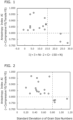


 where, a content of a corresponding element in percent by mass is substituted for each symbol of an element in Formula (1).