EP4461679A1 - Conveyor and image forming apparatus - Google Patents
Conveyor and image forming apparatus Download PDFInfo
- Publication number
- EP4461679A1 EP4461679A1 EP24174475.4A EP24174475A EP4461679A1 EP 4461679 A1 EP4461679 A1 EP 4461679A1 EP 24174475 A EP24174475 A EP 24174475A EP 4461679 A1 EP4461679 A1 EP 4461679A1
- Authority
- EP
- European Patent Office
- Prior art keywords
- guide plate
- sheet
- roller
- hinge shaft
- shaft
- Prior art date
- Legal status (The legal status is an assumption and is not a legal conclusion. Google has not performed a legal analysis and makes no representation as to the accuracy of the status listed.)
- Pending
Links
- 238000011144 upstream manufacturing Methods 0.000 claims description 5
- 230000007246 mechanism Effects 0.000 description 34
- 239000000976 ink Substances 0.000 description 19
- 239000007788 liquid Substances 0.000 description 16
- 238000001816 cooling Methods 0.000 description 9
- 238000012937 correction Methods 0.000 description 9
- 238000001035 drying Methods 0.000 description 8
- 238000000034 method Methods 0.000 description 6
- 230000015572 biosynthetic process Effects 0.000 description 5
- 238000012805 post-processing Methods 0.000 description 4
- 238000007781 pre-processing Methods 0.000 description 4
- 239000000806 elastomer Substances 0.000 description 3
- 230000002093 peripheral effect Effects 0.000 description 3
- VSKJLJHPAFKHBX-UHFFFAOYSA-N 2-methylbuta-1,3-diene;styrene Chemical compound CC(=C)C=C.C=CC1=CC=CC=C1.C=CC1=CC=CC=C1 VSKJLJHPAFKHBX-UHFFFAOYSA-N 0.000 description 2
- FACXGONDLDSNOE-UHFFFAOYSA-N buta-1,3-diene;styrene Chemical compound C=CC=C.C=CC1=CC=CC=C1.C=CC1=CC=CC=C1 FACXGONDLDSNOE-UHFFFAOYSA-N 0.000 description 2
- 230000008859 change Effects 0.000 description 2
- 229920001971 elastomer Polymers 0.000 description 2
- 239000000463 material Substances 0.000 description 2
- 230000008569 process Effects 0.000 description 2
- 229920000468 styrene butadiene styrene block copolymer Polymers 0.000 description 2
- 230000001629 suppression Effects 0.000 description 2
- 229920003051 synthetic elastomer Polymers 0.000 description 2
- -1 white Substances 0.000 description 2
- 241000531908 Aramides Species 0.000 description 1
- 229920000049 Carbon (fiber) Polymers 0.000 description 1
- JOYRKODLDBILNP-UHFFFAOYSA-N Ethyl urethane Chemical compound CCOC(N)=O JOYRKODLDBILNP-UHFFFAOYSA-N 0.000 description 1
- 239000004743 Polypropylene Substances 0.000 description 1
- 239000004676 acrylonitrile butadiene styrene Substances 0.000 description 1
- 229920003235 aromatic polyamide Polymers 0.000 description 1
- 230000000740 bleeding effect Effects 0.000 description 1
- 239000004917 carbon fiber Substances 0.000 description 1
- 239000011248 coating agent Substances 0.000 description 1
- 238000000576 coating method Methods 0.000 description 1
- 239000003086 colorant Substances 0.000 description 1
- 230000000694 effects Effects 0.000 description 1
- 150000002148 esters Chemical class 0.000 description 1
- 239000004744 fabric Substances 0.000 description 1
- PCHJSUWPFVWCPO-UHFFFAOYSA-N gold Chemical compound [Au] PCHJSUWPFVWCPO-UHFFFAOYSA-N 0.000 description 1
- 229910052737 gold Inorganic materials 0.000 description 1
- 239000010931 gold Substances 0.000 description 1
- 238000005470 impregnation Methods 0.000 description 1
- 230000006872 improvement Effects 0.000 description 1
- 238000003780 insertion Methods 0.000 description 1
- 230000037431 insertion Effects 0.000 description 1
- 238000009434 installation Methods 0.000 description 1
- 239000002184 metal Substances 0.000 description 1
- 229910052751 metal Inorganic materials 0.000 description 1
- 238000012986 modification Methods 0.000 description 1
- 230000004048 modification Effects 0.000 description 1
- 229920006285 olefinic elastomer Polymers 0.000 description 1
- 239000002985 plastic film Substances 0.000 description 1
- 229920006255 plastic film Polymers 0.000 description 1
- 229920001155 polypropylene Polymers 0.000 description 1
- 230000009467 reduction Effects 0.000 description 1
- 229920005989 resin Polymers 0.000 description 1
- 239000011347 resin Substances 0.000 description 1
- 238000005096 rolling process Methods 0.000 description 1
- 229910052709 silver Inorganic materials 0.000 description 1
- 239000004332 silver Substances 0.000 description 1
- 238000002466 solution-enhanced dispersion by supercritical fluid Methods 0.000 description 1
- 239000005061 synthetic rubber Substances 0.000 description 1
- 229920005992 thermoplastic resin Polymers 0.000 description 1
Images


Classifications
-
- B—PERFORMING OPERATIONS; TRANSPORTING
- B65—CONVEYING; PACKING; STORING; HANDLING THIN OR FILAMENTARY MATERIAL
- B65H—HANDLING THIN OR FILAMENTARY MATERIAL, e.g. SHEETS, WEBS, CABLES
- B65H5/00—Feeding articles separated from piles; Feeding articles to machines
- B65H5/06—Feeding articles separated from piles; Feeding articles to machines by rollers or balls, e.g. between rollers
- B65H5/062—Feeding articles separated from piles; Feeding articles to machines by rollers or balls, e.g. between rollers between rollers or balls
-
- B—PERFORMING OPERATIONS; TRANSPORTING
- B65—CONVEYING; PACKING; STORING; HANDLING THIN OR FILAMENTARY MATERIAL
- B65H—HANDLING THIN OR FILAMENTARY MATERIAL, e.g. SHEETS, WEBS, CABLES
- B65H9/00—Registering, e.g. orientating, articles; Devices therefor
- B65H9/002—Registering, e.g. orientating, articles; Devices therefor changing orientation of sheet by only controlling movement of the forwarding means, i.e. without the use of stop or register wall
-
- B—PERFORMING OPERATIONS; TRANSPORTING
- B65—CONVEYING; PACKING; STORING; HANDLING THIN OR FILAMENTARY MATERIAL
- B65H—HANDLING THIN OR FILAMENTARY MATERIAL, e.g. SHEETS, WEBS, CABLES
- B65H29/00—Delivering or advancing articles from machines; Advancing articles to or into piles
- B65H29/12—Delivering or advancing articles from machines; Advancing articles to or into piles by means of the nip between two, or between two sets of, moving tapes or bands or rollers
-
- B—PERFORMING OPERATIONS; TRANSPORTING
- B65—CONVEYING; PACKING; STORING; HANDLING THIN OR FILAMENTARY MATERIAL
- B65H—HANDLING THIN OR FILAMENTARY MATERIAL, e.g. SHEETS, WEBS, CABLES
- B65H29/00—Delivering or advancing articles from machines; Advancing articles to or into piles
- B65H29/52—Stationary guides or smoothers
-
- B—PERFORMING OPERATIONS; TRANSPORTING
- B65—CONVEYING; PACKING; STORING; HANDLING THIN OR FILAMENTARY MATERIAL
- B65H—HANDLING THIN OR FILAMENTARY MATERIAL, e.g. SHEETS, WEBS, CABLES
- B65H5/00—Feeding articles separated from piles; Feeding articles to machines
- B65H5/36—Article guides or smoothers, e.g. movable in operation
-
- B—PERFORMING OPERATIONS; TRANSPORTING
- B65—CONVEYING; PACKING; STORING; HANDLING THIN OR FILAMENTARY MATERIAL
- B65H—HANDLING THIN OR FILAMENTARY MATERIAL, e.g. SHEETS, WEBS, CABLES
- B65H9/00—Registering, e.g. orientating, articles; Devices therefor
- B65H9/16—Inclined tape, roller, or like article-forwarding side registers
- B65H9/166—Roller
-
- B—PERFORMING OPERATIONS; TRANSPORTING
- B65—CONVEYING; PACKING; STORING; HANDLING THIN OR FILAMENTARY MATERIAL
- B65H—HANDLING THIN OR FILAMENTARY MATERIAL, e.g. SHEETS, WEBS, CABLES
- B65H2301/00—Handling processes for sheets or webs
- B65H2301/30—Orientation, displacement, position of the handled material
- B65H2301/36—Positioning; Changing position
- B65H2301/361—Positioning; Changing position during displacement
- B65H2301/3613—Lateral positioning
-
- B—PERFORMING OPERATIONS; TRANSPORTING
- B65—CONVEYING; PACKING; STORING; HANDLING THIN OR FILAMENTARY MATERIAL
- B65H—HANDLING THIN OR FILAMENTARY MATERIAL, e.g. SHEETS, WEBS, CABLES
- B65H2404/00—Parts for transporting or guiding the handled material
- B65H2404/10—Rollers
- B65H2404/14—Roller pairs
- B65H2404/142—Roller pairs arranged on movable frame
- B65H2404/1421—Roller pairs arranged on movable frame rotating, pivoting or oscillating around an axis, e.g. parallel to the roller axis
- B65H2404/14212—Roller pairs arranged on movable frame rotating, pivoting or oscillating around an axis, e.g. parallel to the roller axis rotating, pivoting or oscillating around an axis perpendicular to the roller axis
-
- B—PERFORMING OPERATIONS; TRANSPORTING
- B65—CONVEYING; PACKING; STORING; HANDLING THIN OR FILAMENTARY MATERIAL
- B65H—HANDLING THIN OR FILAMENTARY MATERIAL, e.g. SHEETS, WEBS, CABLES
- B65H2404/00—Parts for transporting or guiding the handled material
- B65H2404/10—Rollers
- B65H2404/15—Roller assembly, particular roller arrangement
- B65H2404/152—Arrangement of roller on a movable frame
- B65H2404/1521—Arrangement of roller on a movable frame rotating, pivoting or oscillating around an axis, e.g. parallel to the roller axis
- B65H2404/15212—Arrangement of roller on a movable frame rotating, pivoting or oscillating around an axis, e.g. parallel to the roller axis rotating, pivoting or oscillating around an axis perpendicular to the roller axis
-
- B—PERFORMING OPERATIONS; TRANSPORTING
- B65—CONVEYING; PACKING; STORING; HANDLING THIN OR FILAMENTARY MATERIAL
- B65H—HANDLING THIN OR FILAMENTARY MATERIAL, e.g. SHEETS, WEBS, CABLES
- B65H2404/00—Parts for transporting or guiding the handled material
- B65H2404/10—Rollers
- B65H2404/19—Other features of rollers
-
- B—PERFORMING OPERATIONS; TRANSPORTING
- B65—CONVEYING; PACKING; STORING; HANDLING THIN OR FILAMENTARY MATERIAL
- B65H—HANDLING THIN OR FILAMENTARY MATERIAL, e.g. SHEETS, WEBS, CABLES
- B65H2404/00—Parts for transporting or guiding the handled material
- B65H2404/50—Surface of the elements in contact with the forwarded or guided material
- B65H2404/53—Surface of the elements in contact with the forwarded or guided material with particular mechanical, physical properties
- B65H2404/532—Surface of the elements in contact with the forwarded or guided material with particular mechanical, physical properties with particular durometer
-
- B—PERFORMING OPERATIONS; TRANSPORTING
- B65—CONVEYING; PACKING; STORING; HANDLING THIN OR FILAMENTARY MATERIAL
- B65H—HANDLING THIN OR FILAMENTARY MATERIAL, e.g. SHEETS, WEBS, CABLES
- B65H2404/00—Parts for transporting or guiding the handled material
- B65H2404/50—Surface of the elements in contact with the forwarded or guided material
- B65H2404/53—Surface of the elements in contact with the forwarded or guided material with particular mechanical, physical properties
- B65H2404/532—Surface of the elements in contact with the forwarded or guided material with particular mechanical, physical properties with particular durometer
- B65H2404/5322—Surface of the elements in contact with the forwarded or guided material with particular mechanical, physical properties with particular durometer surface with different hardness
-
- B—PERFORMING OPERATIONS; TRANSPORTING
- B65—CONVEYING; PACKING; STORING; HANDLING THIN OR FILAMENTARY MATERIAL
- B65H—HANDLING THIN OR FILAMENTARY MATERIAL, e.g. SHEETS, WEBS, CABLES
- B65H2404/00—Parts for transporting or guiding the handled material
- B65H2404/60—Other elements in face contact with handled material
- B65H2404/61—Longitudinally-extending strips, tubes, plates, or wires
- B65H2404/611—Longitudinally-extending strips, tubes, plates, or wires arranged to form a channel
-
- B—PERFORMING OPERATIONS; TRANSPORTING
- B65—CONVEYING; PACKING; STORING; HANDLING THIN OR FILAMENTARY MATERIAL
- B65H—HANDLING THIN OR FILAMENTARY MATERIAL, e.g. SHEETS, WEBS, CABLES
- B65H2515/00—Physical entities not provided for in groups B65H2511/00 or B65H2513/00
- B65H2515/81—Rigidity; Stiffness; Elasticity
-
- B—PERFORMING OPERATIONS; TRANSPORTING
- B65—CONVEYING; PACKING; STORING; HANDLING THIN OR FILAMENTARY MATERIAL
- B65H—HANDLING THIN OR FILAMENTARY MATERIAL, e.g. SHEETS, WEBS, CABLES
- B65H2801/00—Application field
- B65H2801/03—Image reproduction devices
- B65H2801/06—Office-type machines, e.g. photocopiers
Definitions
- the present embodiment relates to a conveyor and an image forming apparatus, and particularly relates to a conveyor including an inclinable roller shaft and an image forming apparatus including the conveyor.
- Japanese Unexamined Patent Application Publication No. H08-245019 discloses a registration technique for a conveyor that conveys cut sheets.
- the position of a sheet is automatically corrected for drawing an image at a desired position on the sheet.
- one (inclination roller) of a pair of rollers for nipping and conveying the sheet is inclined.
- the inclination roller has a limited inclination range that restricts a range of automatic correction.
- an image forming apparatus typically performs double-sided print in which both sides of a sheet are subjected to print.
- a conveyance path is long for reversing the sheet in a double-sided conveyance path.
- an apparatus like an inkjet printer that performs sheet drying and sheet cooling after image formation is large and long in size for a drying process and a cooling process.
- the positional shift (amount of shift) of the sheet increases as the sheet is conveyed downstream in the conveyance direction.
- the positional shift of the sheet is affected by factors different in individual conveyors, such as the dimensional tolerance of various components of the conveyors and the parallelism of housings of the conveyors. Therefore, the positional shift of the sheet exceeds an allowance range of automatic correction in such a conventional registration technique as described above.
- the present embodiment has been made in view of such situations, and an object of the present embodiment is to provide a conveyor that facilitates correction of the positional shift of a conveyance target.
- a conveyor includes: a first guide plate including: a first roller shaft; and a first roller having a first hardness and attached to the first roller shaft; and a second guide plate disposed opposite to the first guide plate and including: a second roller shaft; a second roller having a second hardness higher than the first hardness of the first roller and attached to the second roller shaft, wherein parallelism between the first roller shaft and the second roller shaft is variable, and the first guide plate and the second guide plate guide the target, and the first roller and the second roller nips and conveys the target in a conveyance direction.
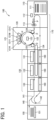
- FIG. 1 is a schematic configuration view of an inkjet printer 100 as an image forming apparatus large in size.
- the inkjet printer 100 mainly includes a sheet feeder 110, an image former 120, a dryer/cooler 130, a sheet reverser 140, a sheet ejector 150, and a positional adjustment mechanism 160.
- a sheet P in the sheet feeder 110 is conveyed to the sheet ejector 150 by a conveyor with a roller and a belt.
- image formation used in the following description means not only giving an image having a meaning such as a character and a figure to a medium, but also giving an image having no meaning such as a pattern to a medium.
- an image is formed, by the image former 120, on the sheet P that is a recording material as a sheet material fed from the sheet feeder 110, with ink as a liquid for image formation. Then, the ink attached on the sheet P is dried by the dryer/cooler 130 before the sheet is ejected to the sheet ejector 150.
- the sheet feeder 110 mainly includes a sheet feeding tray 111 for stacking a plurality of sheets P thereon, a feeding device 112 that one-by-one separates the sheets P from the sheet feeding tray 111 to send the separated sheet P, and a pair of registration rollers 113 that sends the sheet P into the image former 120.
- Any feeding device such as a device with a roller or a rolling element or such as a device using air suction may be used as the feeding device 112.
- the pair of registration rollers 113 is driven at a predetermined timing to feed the sheet P to the image former 120.
- the sheet feeder 110 is not limited in configuration as long as the sheet feeder 110 feeds a sheet P to the image former 120.
- the image former 120 mainly includes an ink discharger 121, a sheet carrying drum 122, a suction device 123, a reception barrel 124, and a delivery barrel 125.
- the reception barrel 124 receives the fed sheet P.
- the sheet carrying drum 122 conveys the sheet P conveyed by the reception barrel 124 with carrying the sheet P on the outer peripheral face of the sheet carrying drum 122.
- the ink discharger 121 discharges ink toward the sheet P carried by the sheet carrying drum 122.
- the delivery barrel 125 delivers the sheet P conveyed by the sheet carrying drum 122 to the dryer/cooler 130.
- the leading end of the sheet P conveyed from the sheet feeder 110 to the image former 120 is gripped by a sheet gripper provided on the surface of the reception barrel 124.
- the sheet P is conveyed along with the surface movement of the reception barrel 124.
- the sheet P conveyed by the reception barrel 124 is delivered to the sheet carrying drum 122 at a position opposed to the sheet carrying drum 122.
- a sheet gripper is also provided on the surface of the sheet carrying drum 122, and the leading end of the sheet P is gripped by the sheet gripper.
- the surface of the sheet carrying drum 122 has a plurality of suction holes dispersed.
- an intake airflow toward the inside of the sheet carrying drum 122 is generated by the suction device 123.
- the sheet P delivered from the reception barrel 124 to the sheet carrying drum 122 is attracted, with the leading end gripped by the sheet gripper, to the surface of the sheet carrying drum 122 by the intake airflow.
- the sheet P is conveyed along with the surface movement of the sheet carrying drum 122.
- the ink discharger 121 of the present embodiment discharges inks of four colors of cyan (C), magenta (M), yellow (Y), and black (K) to form an image.
- the ink discharger 121 includes liquid discharge heads 121C, 121M, 121Y, and 121K one-to-one corresponding to the inks.
- the liquid discharge heads 121C, 121M, 121Y, and 121K are not limited in configuration as long as the liquid discharge heads 121C, 121M, 121Y, and 121K discharge liquid, and thus any configuration is adoptable.
- a liquid discharge head that discharges special ink such as white, gold, or silver may be provided, or a liquid discharge head that discharges a liquid such as a surface coating liquid that does not form an image may be provided.
- each of the liquid discharge heads 121C, 121M, 121Y, 121K of the ink discharger 121 is controlled on the basis of a drive signal corresponding to image information.
- the respective color inks are discharged from the liquid discharge heads 121C, 121M, 121Y, and 121K to form an image corresponding to the image information.
- the image former 120 is not limited in configuration as long as the image former 120 forms an image by attaching liquid onto a sheet P.
- the dryer/cooler 130 mainly includes drying/cooling mechanisms 131, 132, and 133 for drying and cooling such an ink as described above that is attached on the sheet P by the image former 120, and a conveyance mechanism for conveying the sheet P conveyed from the image former 120 by a belt conveyor.
- the sheet P conveyed from the image former 120 is received by the conveyance mechanism. Then, the sheet P is conveyed so as to pass the drying/cooling mechanisms 131, 132, and 133 in order, and delivered to the sheet ejector 150.
- the ink on the sheet P is subjected to drying and cooling.
- liquid components such as moisture in the ink on the sheet P evaporate, and the ink adheres to the sheet P. Further, curling of the sheet P is suppressed by the cooling.
- the sheet reverser 140 includes a bifurcating part 141 and a switchback part 142.
- a sheet P for single-sided print passes the bifurcating part 141 and is conveyed to the sheet ejector 150.
- a sheet P for double-sided print is conveyed downward from the bifurcating part 141.
- the sheet P for double-sided print is reversed through the switchback part 142, and then conveyed to the image former 120 again.
- the positional adjustment mechanism including three units of positional adjustment mechanisms 160 is disposed.
- the positional adjustment mechanisms 160 are located in succession in the conveyance direction of the sheet P.
- the positional adjustment mechanisms 160 are disposed below the dryer/cooler 130.
- the positional adjustment mechanisms 160 each include a plurality of roller shafts for conveying a sheet P. Any of the roller shafts is inclined to correct the amount of shift of the sheet P.
- the positional adjustment mechanisms 160 are provided in a conveyance path through which a sheet P passes in double-sided print. Thus, the conveyance of the first face of the sheet P in single-sided print smaller in the amount of shift is not affected and the conveyance state of the second face of the sheet P in double-sided print larger in the amount of shift can be improved.
- the positional adjustment mechanisms 160 perform positional adjustment across the plurality of units. Thus, a decrease in the inclination angle of each roller shaft of each positional adjustment mechanism 160 results in suppression of the stress of the sheet P between an inclined roller shaft and a non-inclined roller shaft, and a large positional correction effect can be obtained.
- the sheet ejector 150 mainly includes a sheet ejection tray 151 for stacking a plurality of sheets P thereon.
- the sheet P conveyed through the sheet reverser 140 is sequentially stacked and kept on the sheet ejection tray 151.
- the sheet ejector 150 is not limited in configuration as long as the sheet ejector 150 ejects a sheet P.
- a pre-processing unit that performs pre-processing for image formation can be added between the sheet feeder 110 and the image former 120.
- the pre-processing unit include a unit that performs a treatment-liquid application to apply a treatment liquid onto a sheet P and make the treatment liquid react with the ink for reduction of bleeding.
- the details of the pre-processing are not particularly limited.
- a post-processing unit that performs post-processing for image formation can be added before the sheet ejector 150.
- Examples of the post-processing unit include a unit that performs binding a plurality of sheets with images formed thereon and a correction mechanism for correcting sheet deformation.
- the details of the post-processing are not particularly limited.
- FIGS. 2A and 2B illustrate the basic configuration of such a positional adjustment mechanism 160 as described above that is included in the conveyor of the present embodiment.
- the positional adjustment mechanism 160 includes a pair of a first guide plate 161 and a second guide plate 162.
- the upper first guide plate 161 serves as a secured guide plate 161.
- the lower second guide plate 162 serves as a movable guide plate 162.
- the secured guide plate 161 and the movable guide plate 162 convey a sheet P from the left side to the right side in FIG. 2A with guiding the upper and lower faces of the sheet P.
- the secured guide plate 161 is disposed to be horizontally secured.
- the movable guide plate 162 is disposed openably with respect to the secured guide plate 161.
- an end on the rear side of the secured guide plate 161 and an end on the rear side of the movable guide plate 162 are coupled through a hinge shaft 163.
- the hinge shaft 163 is disposed in parallel to the conveyance direction of the sheet P.
- the other end on the front side of the movable guide plate 162 opposite the hinge shaft 163 is turnable in the up- and-down direction about the hinge shaft 163.
- the hinge shaft 163 has an end and the other end in the longitudinal direction. The end and the other end can be supported by a left-and-right pair of bearings provided on the secured guide plate 161. The other end on the front side of the movable guide plate 162 is engageable and lockable with the other end on the front side of the secured guide plate 161 by a locking means.
- FIG. 2B is a bottom view of the positional adjustment mechanism 160 with the secured guide plate 161 and the movable guide plate 162 in FIG. 2A omitted.
- the first roller shaft 166 has first roller members 166a attached thereto.
- the second roller shaft 167 has second roller members 167a attached thereto.
- the sheet P is sent between the first roller members 166a attached to the first roller shaft 166 and the second roller members 167a attached to the second roller shaft 167. Then, the sheet P is nipped and conveyed by the first roller members 166a and the second roller members 167a.
- At least one of the first roller shaft 166 and the second roller shaft 167 is coupled to a driving means such that the at least one can be driven to rotate.
- the first roller members 166a and the second roller members 167a can be made identical in diameter and length with an elastic body made of, for example, synthetic rubber or elastomer. However, the first roller members 166a and the second roller members 167a are different in hardness (surface hardness).
- the second roller members 167a of the second roller shaft 167 that has a variable inclination angle are higher in hardness than the first roller members 166a. This is because, as disclosed in Non-Patent Literature 1, the conveyance direction of the sheet P is affected by a roller member relatively higher in hardness.
- the surface hardness of the first roller members 166a and the second roller members 167a can be measured with, for example, Asker Durometer Type C or a durometer.
- a first roller member 166a for example, used can be a low hardness elastomer (olefinic elastomer such as styrene butadiene styrene (SBS), styrene isoprene styrene (SIS), or SEDS) having, for example, a durometer-based hardness of 20 to 50.
- SBS styrene butadiene styrene
- SIS styrene isoprene styrene
- SEDS styrene isoprene styrene having, for example, a durometer-based hardness of 20 to 50.
- a second roller member 167a for example, used can be a slightly-high hardness elastomer (ester-based, urethane-based, or aramide-based) or a slightly-high hardness thermoplastic resin such as polypropylene or acrylonitrile butadiene styrene (ABS) within the range of the durometer-based hardness of 65 to 80 such as the durometer-based hardness of 74.
- a slightly-high hardness elastomer esteer-based, urethane-based, or aramide-based
- a slightly-high hardness thermoplastic resin such as polypropylene or acrylonitrile butadiene styrene (ABS) within the range of the durometer-based hardness of 65 to 80 such as the durometer-based hardness of 74.
- the movable guide plate 162 including the roller shafts 167 is openable with respect to the secured guide plate 161 as indicated by a double arrow in FIG. 2A , and the movable guide plate 162 is also turnable as described later.
- the roller shaft 167 is inclined such that the conveyance direction of the sheet P is changed to a direction indicated by open arrows in FIG. 2B . That is, in a case where the sheet P conveyed from the left side in FIG. 2B is shifted downward by D from the normal position, the amount of shift D is canceled.
- the end on the rear side of the secured guide plate 161 has a lower face from which a pivot pin 161b protrudes, and the pivot pin 161b is located near the hinge shaft 163.
- the end on the rear side of the secured guide plate 161 and the end on the rear side of the movable guide plate 162 are turnably coupled through the pivot pin 161b.
- the other end on the front side of the secured guide plate 161 has a lower face from which an engagement pin 161a protrudes.
- the engagement pin 161a is located at a position opposite the pivot pin 161b.
- the other end on the front side of the secured guide plate 161 and the other end on the front side of the movable guide plate 162 can be engaged through the engagement pin 161a.
- the other end on the front side of the movable guide plate 162 has an upper face on which an adjustment plate 165 is disposed.
- the adjustment plate 165 as an engagement member is disposed so as to be engaged with the engagement pin 161a.
- the adjustment plate 165 has an engagement hole 165a.
- the engagement pin 161a is fit into the engagement hole 165a of the adjustment plate 165 such that the relative positional relationship between the secured guide plate 161 and the movable guide plate 162 is kept constant.
- the adjustment plate 165 is attachable to the movable guide plate 162 such that the positional adjustment of the adjustment plate 165 can be made in the left-and-right direction (conveyance direction) in FIG. 3A .
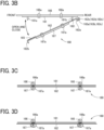
- FIGS. 3A to 3D illustrate an embodiment in which the secured guide plate 161 is provided with a left-and-right pair of roller shafts 166 and the movable guide plate 162 is provided with a left-and-right pair of roller shafts 167. Because the sheet P is conveyed by the left-and-right pair of roller shafts 166 and the left-and-right pair of the roller shafts 167, the sheet conveyance force and the shift adjustment force are improved.
- the respective inclination angles of the two roller shafts 167 can be adjusted together by adjustment of the movable guide plate 162.
- the secured guide plate 161 may be provided with three or more roller shafts and the movable guide plate 162 may be provided with three or more roller shafts.
- the secured guide plate 161 is provided with each rectangular cutout hole 161h through which the corresponding first roller member 166a of each first roller shaft 166 protrudes inward the secured guide plate 161.
- the movable guide plate 162 is provided with each rectangular cutout hole 162h through which the corresponding second roller member 167a of each second roller shaft 167 protrudes inward the movable guide plate 162. Part of the outer peripheral face of the first roller member 166a protrudes inward the secured guide plate 161 through the cutout hole 161h. Part of the outer peripheral face of the second roller member 167a protrudes inward the movable guide plate 162 through the cutout hole 162h.
- the roller shafts 166 and 167 are rotatably supported by bearings disposed outside the secured guide plate 161 and the movable guide plate 162.
- the movable guide plate 162 has a bent part 162a and a bent part 162b each having an L-shape.
- the bent part 162a and the bent part 162b are located, respectively, at the end on the rear side and the other end on the front side of the movable guide plate 162.
- the bent parts 162a and 162b improve the rigidity and strength of the movable guide plate 162.
- the bent part 162a at the end on the rear side is integrally provided with three brackets 162c, 162d, and 162e. These three brackets 162c, 162d, and 162e are disposed at equal intervals in the conveyance direction, for insertion and support of three hinge shafts 163a, 163b, and 163c.
- the three hinge shafts 163a, 163b, and 163c are disposed in a straight line in the conveyance direction.
- the three hinge shafts 163a, 163b, and 163c are a first hinge shaft 163a, a second hinge shaft 163b, and a third hinge shaft 163c, respectively, from the upstream side in the conveyance direction.
- the brackets 162c, 162d, and 162e respectively, have receiving holes 162d, 162d1, and 162e1 through which the corresponding hinge shafts 163a, 163b, and 163c are inserted.
- the receiving holes 162c1 and 162e1 at both ends of the bent part 162a are long holes extending in the conveyance direction.
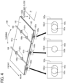
- the central receiving hole 162d1 has a circular shape through which the second hinge shaft 163b can be inserted without looseness. Therefore, when the movable guide plate 162 turns (horizontally turns) in a direction indicated by a double arrow in FIG. 4 about the pivot pin 161b inserted in a pin hole 162i in FIG. 3B near the second hinge shaft 163b, the first hinge shaft 163a and the third hinge shaft 163c are movable in the left-and-right direction in the receiving holes 162c1 and 162e1 at both ends of the bent part 162a. That is, the receiving hole 162c1 and the receiving hole 162e1 in long hole shape each have looseness allowing the movable guide plate 162 to turn (horizontally turn) in the arrow direction of FIG. 4 about the pivot pin 161b.
- the engagement hole 165a of the adjustment plate 165 is a long hole extending in a direction perpendicular to the conveyance direction or the hinge shaft 163. This is because the engagement pin 161a is smoothly inserted into the engagement hole 165a of the adjustment plate 165. However, there is almost no looseness between the engagement pin 161a and the engagement hole 165a in the left-and-right direction (conveyance direction) in FIG. 3A .
- An adjustment hole 165b and another adjustment hole 165b are provided, respectively, on the left side and the right side of the engagement hole 165a of the adjustment plate 165.
- the adjustment hole 165b and the other adjustment hole 165b are paired.
- a screw hole 162f and another screw hole 162f are provided at positions one-to-one corresponding to the adjustment hole 165b and the other adjustment hole 165b.
- the screw hole 162f and the other screw hole 162f are paired.
- a plurality of (seven in the illustrated example) adjustment holes 165c are provided in front of the engagement hole 165a of the adjustment plate 165 at equal intervals in the conveyance direction.
- the other end on the front side of the movable guide plate 162 has a plurality of screw holes 162g one-to-one corresponding to the plurality of adjustment holes 165c.
- the pitch of the screw holes 162g is slightly shifted from the pitch of the adjustment holes 165c.
- the adjustment plate 165 can be screwed to the movable guide plate 162 with the central adjustment hole 165c among the plurality of adjustment holes 165c aligned with any one of the screw holes 162g.
- the central adjustment hole 165c is aligned with the central screw hole 162g.
- the adjustment plate 165 is screwed to the movable guide plate 162 with this alignment, so that the movable guide plate 162 has a turning angle of 0 with respect to the secured guide plate 161.
- any of left or right screw holes 162g is selected as the screw hole 162g with which the central adjustment hole 165c is aligned.
- the adjustment plate 165 is screwed with the central adjustment hole 165c aligned with the selected screw hole 162g, so that the movable guide plate 162 can have a positive turning angle or a negative turning angle with respect to the secured guide plate 161.
- the positive or negative alignment of the adjustment plate 165 can be easily performed due to the shape of the screw hole 162g viewed through the corresponding adjustment hole 165c. Therefore, the movable guide plate 162 and the inclination angle of such a second roller shaft 167 as described above can be easily fixed to target values.
- the conveyor and the positional adjustment mechanism of the present embodiment have the configurations as described above.
- the positional shift (amount of shift) of a sheet may be increased and may exceed an allowance range of automatic correction.
- the positional shift of the sheet is affected by factors different in individual conveyors.
- the above-described positional adjustment of the movable guide plate 162 and the adjustment plate 165 can be performed so as to cancel the amount of shift corresponding to the amount of shift acquired by experimental conveyance of a sheet P. Specifically, measured is the amount of shift of a specific sheet P when the specific sheet P started to be conveyed from the sheet feeder 110 returns to the feeding device 112 again through the sheet reverser 140. Then, the inclination angle of the roller shaft 167 is determined by the positional adjustment of the movable guide plate 162 and the adjustment plate 165 such that the amount of shift becomes 0 by the three positional adjustment mechanisms 160.
- All the roller shafts 167 of the three positional adjustment mechanisms 160 are each set to have a certain inclination angle. With this arrangement, the amount of shift correction for the sheet P is made uniform by each positional adjustment mechanism 160, resulting in improvement in accuracy of the positional adjustment. Further, the shift correction is performed in stages, resulting in suppression of damage to the sheet P.
- the inclination angles of the roller shafts 167 of the three positional adjustment mechanisms 160 are not necessarily required to be uniform to a certain inclination angle.
- the most upstream roller shaft 167 through which the sheet P passes may have a smallest inclination angle and a more downstream roller shaft 167 may have a larger inclination angle.
- This arrangement results in a smooth shift correction for a sheet P particularly in high-speed conveyance.
- a positional adjustment mechanism 160 as described above can be added easily and at low cost in the conveyance direction of the sheet P.
- the cancel adjustment for the amount of shift can be performed regardless of the level of the amount of shift.
- the positional adjustment mechanism 160 looseness a role of coarse adjustment in tendency of a sheet positional shift different in individual conveyors. After adjustment is performed at the time of assembly or installation of a conveyor, regular adjustment is basically eliminated. However, in accordance with a change in the amount of shift to be canceled due to, for example, change of the sheet P to be used for print, the movable guide plate 162 is opened from the front side of the conveyor. As a result, the positions of the movable guide plate 162 and the adjustment plate 165 can be easily readjusted.
- a conveyor includes: a first guide plate (161) including: a first roller shaft; and a first roller having a first hardness and attached to the first roller shaft; and a second guide plate (162) disposed opposite to the first guide plate (161) and including: a second roller shaft; and a second roller having a second hardness higher than the first hardness of the first roller and attached to the second roller shaft, wherein parallelism between the first roller shaft and the second roller shaft is variable, and the first guide plate (161) and the second guide plate (162) guide the target, and the first roller and the second roller nips and conveys the target in a conveyance direction.
- the first guide plate (161) is fixed, and the second guide plate (162) is movable relative to the first guide plate (161) to vary the parallelism between the first roller shaft and the second roller shaft.
- the second guide plate (162) is openably closable with respect to the first guide plate (161).
- the conveyor includes a hinge shaft (163) to couple one end of the first guide plate (161) to one end of the second guide plate (162), wherein another end of the second guide plate (162) is rotatable with respect to another end of the first guide plate (161) about the hinge shaft (163).
- the hinge shaft (163) is parallel to the conveyance direction.
- One of said another end of the first guide plate (161) or said another end of the second guide plate (162) has an adjustment plate (165) having an engagement hole (165a); and another of said another end of the first guide plate (161) or said another end of the second guide plate (162) has an engagement pin (161a) fit into the engagement hole (165a).
- the adjustment plate (165) is attachable to said another end of the second guide plate (162) at variable positions to vary a position of the second guide plate (162) with respect to the first guide plate (161).
- the hinge shaft (163) has a looseness to vary the position of the second guide plate (162) with respect to the first guide plate (161).
- the hinge shaft (163) includes: a first hinge shaft; a second hinge shaft; and a third hinge shaft, disposed in an order from an upstream side to a downstream side in the conveyance direction of the target, and each of the first hinge shaft and the third hinge shaft has a long hole to vary the position of the second guide plate (162) with respect to the first guide plate (161).
- the conveyor includes a pivot pin (161b) through which the one end of the first guide plate (161) and the one end of the second guide plate (162) are coupled in vicinity of the second hinge shaft, and the second guide plate (162) is turnable with respect to the first guide plate (161) about the pivot pin (161b).
- the present embodiment has been specifically described on the basis of the embodiments.
- the present embodiment is not limited to the embodiments, and thus it goes without saying that various modifications can be made within the scope of the technical idea described in the claims.
- the movable guide plate 162 is disposed openably and turnably with respect to the secured guide plate 161.
- the movable guide plate 162, however, is not necessarily required to be movable.
- the parallelism between a first roller shaft 166 including first roller members 166a lower in hardness and a second roller shaft 167 including second roller members 167a higher in hardness may be variable.
- the sheet P has been described as a conveyance target.
- the conveyance target is not limited to the sheet P.
- the conveyance target also includes an overhead projector (OHP) sheet, fabric, a metal sheet, a plastic film, and a prepreg sheet that results from impregnation of carbon fibers with a resin in advance.
- OHP overhead projector
- a medium, recording paper, and a recording sheet to which a developer or ink can be attached are all included in the "conveyance target".
- the "sheet” includes thick paper, a postcard, an envelope, thin paper, coated paper (e.g., a coated sheet and an art sheet), and tracing paper.
- a conveyor includes: a first guide plate including a first roller shaft and a first roller member attached to the first roller shaft; and a second guide plate including a second roller shaft and a second roller member attached to the second roller shaft, the second guide plate being disposed opposite the first guide plate, in which the second roller member is higher in hardness than the first roller member, parallelism between the first roller shaft and the second roller shaft is variable, and the conveyor is configured to convey a conveyance target with the first roller member and the second roller member nipping the conveyance target and with the first guide plate and the second guide plate guiding the conveyance target.
- the first guide plate includes a secured guide plate
- the second guide plate includes a movable guide plate
- the movable guide plate is variable with respect to the secured guide plate such that the parallelism between the first roller shaft and the second roller shaft varies.
- the movable guide plate is openable with respect to the secured guide plate.
- the conveyor of Aspect 3 further includes a hinge shaft, in which an end of the secured guide plate and an end of the movable guide plate are coupled through the hinge shaft such that the movable guide plate is openable with respect to the secured guide plate about the hinge shaft.
- the hinge shaft is disposed in parallel to a conveyance direction of the conveyance target.
- the conveyor of Aspect 5 further includes an engagement member disposed such that the secured guide plate and the movable guide plate are engaged together at another end of the secured guide plate and another end of the movable guide plate that are located opposite to the hinge shaft.
- the engagement member is attachable to said another end of the movable guide plate at any of a plurality of positions allowing the movable guide plate to vary with respect to the secured guide plate.
- the hinge shaft has looseness that allows the movable guide plate to vary.
- the hinge shaft includes a first hinge shaft, a second hinge shaft, and a third hinge shaft disposed from an upstream side to a downstream side in the conveyance direction of the conveyance target, and the first hinge shaft and the third hinge shaft each have the looseness.
- the conveyor of Aspect 9 further includes a pivot pin, in which the end of the secured guide plate and the end of the movable guide plate are coupled through the pivot pin near the second hinge shaft, and the movable guide plate is turnable with respect to the secured guide plate about the pivot pin.
- an image forming apparatus includes the conveyor according to any one of Aspect 1 to Aspect 10.
Landscapes
- Engineering & Computer Science (AREA)
- Mechanical Engineering (AREA)
- Delivering By Means Of Belts And Rollers (AREA)
Abstract
A conveyor includes: a first guide plate (161) including: a first roller shaft; and a first roller having a first hardness and attached to the first roller shaft; and a second guide plate (162) disposed opposite to the first guide plate (161) and including: a second roller shaft; and a second roller having a second hardness higher than the first hardness of the first roller and attached to the second roller shaft, wherein parallelism between the first roller shaft and the second roller shaft is variable, and the first guide plate (161) and the second guide plate (162) guide the target, andthe first roller and the second roller nips and conveys the target in a conveyance direction.
Description
- The present embodiment relates to a conveyor and an image forming apparatus, and particularly relates to a conveyor including an inclinable roller shaft and an image forming apparatus including the conveyor.
-
Japanese Unexamined Patent Application Publication No. H08-245019 - In the recent years, in order to conserve paper resources, an image forming apparatus typically performs double-sided print in which both sides of a sheet are subjected to print. For the double-sided print, a conveyance path is long for reversing the sheet in a double-sided conveyance path. In particular, an apparatus like an inkjet printer that performs sheet drying and sheet cooling after image formation is large and long in size for a drying process and a cooling process.
- In such dry process and cooling process, not roller conveyance but belt conveyance is often performed. Thus, the positional shift (amount of shift) of the sheet increases as the sheet is conveyed downstream in the conveyance direction. The positional shift of the sheet is affected by factors different in individual conveyors, such as the dimensional tolerance of various components of the conveyors and the parallelism of housings of the conveyors. Therefore, the positional shift of the sheet exceeds an allowance range of automatic correction in such a conventional registration technique as described above.
- The present embodiment has been made in view of such situations, and an object of the present embodiment is to provide a conveyor that facilitates correction of the positional shift of a conveyance target.
- In an aspect of the present disclosure, a conveyor includes: a first guide plate including: a first roller shaft; and a first roller having a first hardness and attached to the first roller shaft; and a second guide plate disposed opposite to the first guide plate and including: a second roller shaft; a second roller having a second hardness higher than the first hardness of the first roller and attached to the second roller shaft, wherein parallelism between the first roller shaft and the second roller shaft is variable, and the first guide plate and the second guide plate guide the target, and the first roller and the second roller nips and conveys the target in a conveyance direction.
- A more complete appreciation of embodiments of the present disclosure and many of the attendant advantages and features thereof can be readily obtained and understood from the following detailed description with reference to the accompanying drawings, wherein:
-
FIG. 1 is a schematic configuration view of an image forming apparatus according to an embodiment of the present embodiment; -
FIG. 2A is a perspective view of the basic configuration of a positional adjustment mechanism included in a conveyor according to the embodiment of the present embodiment; -
FIG. 2B is a bottom view of the positional adjustment mechanism inFIG. 2A ; -
FIG. 3A is a perspective view of the positional adjustment mechanism; -
FIG. 3B is a side view of the positional adjustment mechanism with a movable guide plate open, viewed in a conveyance direction; -
FIG. 3C is a side view of roller shafts of the positional adjustment mechanism before variation of the parallelism between the roller shafts; -
FIG. 3D is a side view of the roller shafts of the positional adjustment mechanism after variation of the parallelism between the roller shafts; and -
FIG. 4 is a perspective of the positional adjustment mechanism with the movable guide plate closed. - The accompanying drawings are intended to depict embodiments of the present disclosure and should not be interpreted to limit the scope thereof. The accompanying drawings are not to be considered as drawn to scale unless explicitly noted. Also, identical or similar reference numerals designate identical or similar components throughout the several views.
- In describing embodiments illustrated in the drawings, specific terminology is employed for the sake of clarity. However, the disclosure of this specification is not intended to be limited to the specific terminology so selected and it is to be understood that each specific element includes all technical equivalents that have a similar function, operate in a similar manner, and achieve a similar result.
- Referring now to the drawings, embodiments of the present disclosure are described below. As used herein, the singular forms "a," "an," and "the" are intended to include the plural forms as well, unless the context clearly indicates otherwise.
- An embodiment of the present embodiment will be described below with reference to the accompanying drawings.
FIG. 1 is a schematic configuration view of aninkjet printer 100 as an image forming apparatus large in size. Theinkjet printer 100 mainly includes asheet feeder 110, an image former 120, a dryer/cooler 130, a sheet reverser 140, asheet ejector 150, and apositional adjustment mechanism 160. - A sheet P in the
sheet feeder 110 is conveyed to thesheet ejector 150 by a conveyor with a roller and a belt. Note that "image formation " used in the following description means not only giving an image having a meaning such as a character and a figure to a medium, but also giving an image having no meaning such as a pattern to a medium. - In the
inkjet printer 100, an image is formed, by the image former 120, on the sheet P that is a recording material as a sheet material fed from thesheet feeder 110, with ink as a liquid for image formation. Then, the ink attached on the sheet P is dried by the dryer/cooler 130 before the sheet is ejected to thesheet ejector 150. - The
sheet feeder 110 mainly includes asheet feeding tray 111 for stacking a plurality of sheets P thereon, afeeding device 112 that one-by-one separates the sheets P from thesheet feeding tray 111 to send the separated sheet P, and a pair ofregistration rollers 113 that sends the sheet P into the image former 120. Any feeding device such as a device with a roller or a rolling element or such as a device using air suction may be used as thefeeding device 112. - After the leading end of the sheet P fed from the
sheet feeding tray 111 by thefeeding device 112 reaches the pair ofregistration rollers 113, the pair ofregistration rollers 113 is driven at a predetermined timing to feed the sheet P to the image former 120. Note that, in the present embodiment, thesheet feeder 110 is not limited in configuration as long as thesheet feeder 110 feeds a sheet P to the image former 120. - The image former 120 mainly includes an
ink discharger 121, asheet carrying drum 122, asuction device 123, areception barrel 124, and adelivery barrel 125. Thereception barrel 124 receives the fed sheet P. Thesheet carrying drum 122 conveys the sheet P conveyed by thereception barrel 124 with carrying the sheet P on the outer peripheral face of thesheet carrying drum 122. The ink discharger 121 discharges ink toward the sheet P carried by thesheet carrying drum 122. Thedelivery barrel 125 delivers the sheet P conveyed by thesheet carrying drum 122 to the dryer/cooler 130. - The leading end of the sheet P conveyed from the
sheet feeder 110 to the image former 120 is gripped by a sheet gripper provided on the surface of thereception barrel 124. The sheet P is conveyed along with the surface movement of thereception barrel 124. The sheet P conveyed by thereception barrel 124 is delivered to thesheet carrying drum 122 at a position opposed to thesheet carrying drum 122. - A sheet gripper is also provided on the surface of the
sheet carrying drum 122, and the leading end of the sheet P is gripped by the sheet gripper. The surface of thesheet carrying drum 122 has a plurality of suction holes dispersed. - In each suction hole, an intake airflow toward the inside of the
sheet carrying drum 122 is generated by thesuction device 123. The sheet P delivered from thereception barrel 124 to thesheet carrying drum 122 is attracted, with the leading end gripped by the sheet gripper, to the surface of thesheet carrying drum 122 by the intake airflow. The sheet P is conveyed along with the surface movement of thesheet carrying drum 122. - The
ink discharger 121 of the present embodiment discharges inks of four colors of cyan (C), magenta (M), yellow (Y), and black (K) to form an image. Theink discharger 121 includes liquid discharge heads 121C, 121M, 121Y, and 121K one-to-one corresponding to the inks. - The liquid discharge heads 121C, 121M, 121Y, and 121K are not limited in configuration as long as the liquid discharge heads 121C, 121M, 121Y, and 121K discharge liquid, and thus any configuration is adoptable. A liquid discharge head that discharges special ink such as white, gold, or silver may be provided, or a liquid discharge head that discharges a liquid such as a surface coating liquid that does not form an image may be provided.
- The discharge operation of each of the liquid discharge heads 121C, 121M, 121Y, 121K of the
ink discharger 121 is controlled on the basis of a drive signal corresponding to image information. In passing of the sheet P carried on thesheet carrying drum 122 through a region facing theink discharger 121, the respective color inks are discharged from the liquid discharge heads 121C, 121M, 121Y, and 121K to form an image corresponding to the image information. Note that, in the present embodiment, the image former 120 is not limited in configuration as long as the image former 120 forms an image by attaching liquid onto a sheet P. - The dryer/cooler 130 mainly includes drying/
cooling mechanisms cooling mechanisms sheet ejector 150. - In passing of the sheet P through the drying/
cooling mechanisms - The
sheet reverser 140 includes a bifurcatingpart 141 and aswitchback part 142. A sheet P for single-sided print passes the bifurcatingpart 141 and is conveyed to thesheet ejector 150. A sheet P for double-sided print is conveyed downward from the bifurcatingpart 141. The sheet P for double-sided print is reversed through theswitchback part 142, and then conveyed to the image former 120 again. - On the way of the conveyance from the
switchback part 142 to the image former 120, the positional adjustment mechanism including three units ofpositional adjustment mechanisms 160 is disposed. Thepositional adjustment mechanisms 160 are located in succession in the conveyance direction of the sheet P. Thepositional adjustment mechanisms 160 are disposed below the dryer/cooler 130. Thepositional adjustment mechanisms 160 each include a plurality of roller shafts for conveying a sheet P. Any of the roller shafts is inclined to correct the amount of shift of the sheet P. - The
positional adjustment mechanisms 160 are provided in a conveyance path through which a sheet P passes in double-sided print. Thus, the conveyance of the first face of the sheet P in single-sided print smaller in the amount of shift is not affected and the conveyance state of the second face of the sheet P in double-sided print larger in the amount of shift can be improved. Thepositional adjustment mechanisms 160 perform positional adjustment across the plurality of units. Thus, a decrease in the inclination angle of each roller shaft of eachpositional adjustment mechanism 160 results in suppression of the stress of the sheet P between an inclined roller shaft and a non-inclined roller shaft, and a large positional correction effect can be obtained. - The
sheet ejector 150 mainly includes asheet ejection tray 151 for stacking a plurality of sheets P thereon. The sheet P conveyed through thesheet reverser 140 is sequentially stacked and kept on thesheet ejection tray 151. Note that, in the present embodiment, thesheet ejector 150 is not limited in configuration as long as thesheet ejector 150 ejects a sheet P. - Other functional units can be appropriately added to the
inkjet printer 100 of the present embodiment. For example, a pre-processing unit that performs pre-processing for image formation can be added between thesheet feeder 110 and the image former 120. Examples of the pre-processing unit include a unit that performs a treatment-liquid application to apply a treatment liquid onto a sheet P and make the treatment liquid react with the ink for reduction of bleeding. However, the details of the pre-processing are not particularly limited. - Further, a post-processing unit that performs post-processing for image formation can be added before the
sheet ejector 150. - Examples of the post-processing unit include a unit that performs binding a plurality of sheets with images formed thereon and a correction mechanism for correcting sheet deformation. However, the details of the post-processing are not particularly limited.
-
FIGS. 2A and 2B illustrate the basic configuration of such apositional adjustment mechanism 160 as described above that is included in the conveyor of the present embodiment. Thepositional adjustment mechanism 160 includes a pair of afirst guide plate 161 and asecond guide plate 162. The upperfirst guide plate 161 serves as asecured guide plate 161. The lowersecond guide plate 162 serves as amovable guide plate 162. - The
secured guide plate 161 and themovable guide plate 162 convey a sheet P from the left side to the right side inFIG. 2A with guiding the upper and lower faces of the sheet P. Thesecured guide plate 161 is disposed to be horizontally secured. On the other hand, themovable guide plate 162 is disposed openably with respect to thesecured guide plate 161. - That is, an end on the rear side of the
secured guide plate 161 and an end on the rear side of themovable guide plate 162 are coupled through ahinge shaft 163. Thehinge shaft 163 is disposed in parallel to the conveyance direction of the sheet P. The other end on the front side of themovable guide plate 162 opposite thehinge shaft 163 is turnable in the up- and-down direction about thehinge shaft 163. - The
hinge shaft 163 has an end and the other end in the longitudinal direction. The end and the other end can be supported by a left-and-right pair of bearings provided on thesecured guide plate 161. The other end on the front side of themovable guide plate 162 is engageable and lockable with the other end on the front side of thesecured guide plate 161 by a locking means. - As illustrated in
FIG. 2B , thesecured guide plate 161 includes afirst roller shaft 166, and themovable guide plate 162 includes asecond roller shaft 167.FIG. 2B is a bottom view of thepositional adjustment mechanism 160 with thesecured guide plate 161 and themovable guide plate 162 inFIG. 2A omitted. - The
first roller shaft 166 hasfirst roller members 166a attached thereto. Thesecond roller shaft 167 hassecond roller members 167a attached thereto. The sheet P is sent between thefirst roller members 166a attached to thefirst roller shaft 166 and thesecond roller members 167a attached to thesecond roller shaft 167. Then, the sheet P is nipped and conveyed by thefirst roller members 166a and thesecond roller members 167a. At least one of thefirst roller shaft 166 and thesecond roller shaft 167 is coupled to a driving means such that the at least one can be driven to rotate. - The
first roller members 166a and thesecond roller members 167a can be made identical in diameter and length with an elastic body made of, for example, synthetic rubber or elastomer. However, thefirst roller members 166a and thesecond roller members 167a are different in hardness (surface hardness). - The
second roller members 167a of thesecond roller shaft 167 that has a variable inclination angle are higher in hardness than thefirst roller members 166a. This is because, as disclosed inNon-Patent Literature 1, the conveyance direction of the sheet P is affected by a roller member relatively higher in hardness. - The surface hardness of the
first roller members 166a and thesecond roller members 167a can be measured with, for example, Asker Durometer Type C or a durometer. For such afirst roller member 166a, for example, used can be a low hardness elastomer (olefinic elastomer such as styrene butadiene styrene (SBS), styrene isoprene styrene (SIS), or SEDS) having, for example, a durometer-based hardness of 20 to 50. For such asecond roller member 167a, for example, used can be a slightly-high hardness elastomer (ester-based, urethane-based, or aramide-based) or a slightly-high hardness thermoplastic resin such as polypropylene or acrylonitrile butadiene styrene (ABS) within the range of the durometer-based hardness of 65 to 80 such as the durometer-based hardness of 74. - In the
positional adjustment mechanism 160, themovable guide plate 162 including theroller shafts 167 is openable with respect to thesecured guide plate 161 as indicated by a double arrow inFIG. 2A , and themovable guide plate 162 is also turnable as described later. With this arrangement, as illustrated inFIG. 2B , theroller shaft 167 is inclined such that the conveyance direction of the sheet P is changed to a direction indicated by open arrows inFIG. 2B . That is, in a case where the sheet P conveyed from the left side inFIG. 2B is shifted downward by D from the normal position, the amount of shift D is canceled. - The end on the rear side of the
secured guide plate 161 has a lower face from which apivot pin 161b protrudes, and thepivot pin 161b is located near thehinge shaft 163. The end on the rear side of thesecured guide plate 161 and the end on the rear side of themovable guide plate 162 are turnably coupled through thepivot pin 161b. - The other end on the front side of the
secured guide plate 161 has a lower face from which anengagement pin 161a protrudes. Theengagement pin 161a is located at a position opposite thepivot pin 161b. The other end on the front side of thesecured guide plate 161 and the other end on the front side of themovable guide plate 162 can be engaged through theengagement pin 161a. - The other end on the front side of the
movable guide plate 162 has an upper face on which anadjustment plate 165 is disposed. Theadjustment plate 165 as an engagement member is disposed so as to be engaged with theengagement pin 161a. Theadjustment plate 165 has anengagement hole 165a. Theengagement pin 161a is fit into theengagement hole 165a of theadjustment plate 165 such that the relative positional relationship between thesecured guide plate 161 and themovable guide plate 162 is kept constant. As will be described later with reference toFIG. 3A , theadjustment plate 165 is attachable to themovable guide plate 162 such that the positional adjustment of theadjustment plate 165 can be made in the left-and-right direction (conveyance direction) inFIG. 3A . -
FIGS. 3A to 3D illustrate an embodiment in which thesecured guide plate 161 is provided with a left-and-right pair ofroller shafts 166 and themovable guide plate 162 is provided with a left-and-right pair ofroller shafts 167. Because the sheet P is conveyed by the left-and-right pair ofroller shafts 166 and the left-and-right pair of theroller shafts 167, the sheet conveyance force and the shift adjustment force are improved. - The respective inclination angles of the two
roller shafts 167 can be adjusted together by adjustment of themovable guide plate 162. Thesecured guide plate 161 may be provided with three or more roller shafts and themovable guide plate 162 may be provided with three or more roller shafts. - The
secured guide plate 161 is provided with eachrectangular cutout hole 161h through which the correspondingfirst roller member 166a of eachfirst roller shaft 166 protrudes inward thesecured guide plate 161. Themovable guide plate 162 is provided with eachrectangular cutout hole 162h through which the correspondingsecond roller member 167a of eachsecond roller shaft 167 protrudes inward themovable guide plate 162. Part of the outer peripheral face of thefirst roller member 166a protrudes inward thesecured guide plate 161 through thecutout hole 161h. Part of the outer peripheral face of thesecond roller member 167a protrudes inward themovable guide plate 162 through thecutout hole 162h. Theroller shafts secured guide plate 161 and themovable guide plate 162. - The
movable guide plate 162 has abent part 162a and abent part 162b each having an L-shape. Thebent part 162a and thebent part 162b are located, respectively, at the end on the rear side and the other end on the front side of themovable guide plate 162. Thebent parts movable guide plate 162. - As illustrated in
FIG. 4 , thebent part 162a at the end on the rear side is integrally provided with threebrackets brackets hinge shafts - The three
hinge shafts hinge shafts first hinge shaft 163a, asecond hinge shaft 163b, and athird hinge shaft 163c, respectively, from the upstream side in the conveyance direction. - The
brackets holes 162d, 162d1, and 162e1 through which thecorresponding hinge shafts bent part 162a are long holes extending in the conveyance direction. - On the other hand, the central receiving hole 162d1 has a circular shape through which the
second hinge shaft 163b can be inserted without looseness. Therefore, when themovable guide plate 162 turns (horizontally turns) in a direction indicated by a double arrow inFIG. 4 about thepivot pin 161b inserted in apin hole 162i inFIG. 3B near thesecond hinge shaft 163b, thefirst hinge shaft 163a and thethird hinge shaft 163c are movable in the left-and-right direction in the receiving holes 162c1 and 162e1 at both ends of thebent part 162a. That is, the receiving hole 162c1 and the receiving hole 162e1 in long hole shape each have looseness allowing themovable guide plate 162 to turn (horizontally turn) in the arrow direction ofFIG. 4 about thepivot pin 161b. - The
engagement hole 165a of theadjustment plate 165 is a long hole extending in a direction perpendicular to the conveyance direction or thehinge shaft 163. This is because theengagement pin 161a is smoothly inserted into theengagement hole 165a of theadjustment plate 165. However, there is almost no looseness between theengagement pin 161a and theengagement hole 165a in the left-and-right direction (conveyance direction) inFIG. 3A . - An
adjustment hole 165b and anotheradjustment hole 165b are provided, respectively, on the left side and the right side of theengagement hole 165a of theadjustment plate 165. Theadjustment hole 165b and theother adjustment hole 165b are paired. At the other end on the front side of themovable guide plate 162, ascrew hole 162f and anotherscrew hole 162f are provided at positions one-to-one corresponding to theadjustment hole 165b and theother adjustment hole 165b. Thescrew hole 162f and theother screw hole 162f are paired. - A plurality of (seven in the illustrated example) adjustment holes 165c are provided in front of the
engagement hole 165a of theadjustment plate 165 at equal intervals in the conveyance direction. The other end on the front side of themovable guide plate 162 has a plurality ofscrew holes 162g one-to-one corresponding to the plurality ofadjustment holes 165c. - The pitch of the
screw holes 162g is slightly shifted from the pitch of the adjustment holes 165c. Theadjustment plate 165 can be screwed to themovable guide plate 162 with thecentral adjustment hole 165c among the plurality ofadjustment holes 165c aligned with any one of the screw holes 162g. - In the illustrated example, the
central adjustment hole 165c is aligned with thecentral screw hole 162g. Theadjustment plate 165 is screwed to themovable guide plate 162 with this alignment, so that themovable guide plate 162 has a turning angle of 0 with respect to thesecured guide plate 161. - Any of left or
right screw holes 162g is selected as thescrew hole 162g with which thecentral adjustment hole 165c is aligned. Theadjustment plate 165 is screwed with thecentral adjustment hole 165c aligned with the selectedscrew hole 162g, so that themovable guide plate 162 can have a positive turning angle or a negative turning angle with respect to thesecured guide plate 161. At this time, the positive or negative alignment of theadjustment plate 165 can be easily performed due to the shape of thescrew hole 162g viewed through the correspondingadjustment hole 165c. Therefore, themovable guide plate 162 and the inclination angle of such asecond roller shaft 167 as described above can be easily fixed to target values. - Regarding the positional adjustment, the conveyor and the positional adjustment mechanism of the present embodiment have the configurations as described above. As described above, in an image forming apparatus having a long conveyance path, the positional shift (amount of shift) of a sheet may be increased and may exceed an allowance range of automatic correction. The positional shift of the sheet is affected by factors different in individual conveyors.
- Therefore, the above-described positional adjustment of the
movable guide plate 162 and theadjustment plate 165 can be performed so as to cancel the amount of shift corresponding to the amount of shift acquired by experimental conveyance of a sheet P. Specifically, measured is the amount of shift of a specific sheet P when the specific sheet P started to be conveyed from thesheet feeder 110 returns to thefeeding device 112 again through thesheet reverser 140. Then, the inclination angle of theroller shaft 167 is determined by the positional adjustment of themovable guide plate 162 and theadjustment plate 165 such that the amount of shift becomes 0 by the threepositional adjustment mechanisms 160. - All the
roller shafts 167 of the threepositional adjustment mechanisms 160 are each set to have a certain inclination angle. With this arrangement, the amount of shift correction for the sheet P is made uniform by eachpositional adjustment mechanism 160, resulting in improvement in accuracy of the positional adjustment. Further, the shift correction is performed in stages, resulting in suppression of damage to the sheet P. - The inclination angles of the
roller shafts 167 of the threepositional adjustment mechanisms 160 are not necessarily required to be uniform to a certain inclination angle. The mostupstream roller shaft 167 through which the sheet P passes may have a smallest inclination angle and a moredownstream roller shaft 167 may have a larger inclination angle. - This arrangement results in a smooth shift correction for a sheet P particularly in high-speed conveyance. Such a
positional adjustment mechanism 160 as described above can be added easily and at low cost in the conveyance direction of the sheet P. Thus, the cancel adjustment for the amount of shift can be performed regardless of the level of the amount of shift. - The
positional adjustment mechanism 160 looseness a role of coarse adjustment in tendency of a sheet positional shift different in individual conveyors. After adjustment is performed at the time of assembly or installation of a conveyor, regular adjustment is basically eliminated. However, in accordance with a change in the amount of shift to be canceled due to, for example, change of the sheet P to be used for print, themovable guide plate 162 is opened from the front side of the conveyor. As a result, the positions of themovable guide plate 162 and theadjustment plate 165 can be easily readjusted. - A conveyor includes: a first guide plate (161) including: a first roller shaft; and a first roller having a first hardness and attached to the first roller shaft; and a second guide plate (162) disposed opposite to the first guide plate (161) and including: a second roller shaft; and a second roller having a second hardness higher than the first hardness of the first roller and attached to the second roller shaft, wherein parallelism between the first roller shaft and the second roller shaft is variable, and the first guide plate (161) and the second guide plate (162) guide the target, and the first roller and the second roller nips and conveys the target in a conveyance direction.
- The first guide plate (161) is fixed, and the second guide plate (162) is movable relative to the first guide plate (161) to vary the parallelism between the first roller shaft and the second roller shaft.
- The second guide plate (162) is openably closable with respect to the first guide plate (161).
- The conveyor includes a hinge shaft (163) to couple one end of the first guide plate (161) to one end of the second guide plate (162), wherein another end of the second guide plate (162) is rotatable with respect to another end of the first guide plate (161) about the hinge shaft (163).
- The hinge shaft (163) is parallel to the conveyance direction.
- One of said another end of the first guide plate (161) or said another end of the second guide plate (162) has an adjustment plate (165) having an engagement hole (165a); and another of said another end of the first guide plate (161) or said another end of the second guide plate (162) has an engagement pin (161a) fit into the engagement hole (165a).
- The adjustment plate (165) is attachable to said another end of the second guide plate (162) at variable positions to vary a position of the second guide plate (162) with respect to the first guide plate (161).
- The hinge shaft (163) has a looseness to vary the position of the second guide plate (162) with respect to the first guide plate (161).
- The hinge shaft (163) includes: a first hinge shaft; a second hinge shaft; and a third hinge shaft, disposed in an order from an upstream side to a downstream side in the conveyance direction of the target, and each of the first hinge shaft and the third hinge shaft has a long hole to vary the position of the second guide plate (162) with respect to the first guide plate (161).
- The conveyor includes a pivot pin (161b) through which the one end of the first guide plate (161) and the one end of the second guide plate (162) are coupled in vicinity of the second hinge shaft, and the second guide plate (162) is turnable with respect to the first guide plate (161) about the pivot pin (161b).
- The present embodiment has been specifically described on the basis of the embodiments. The present embodiment, however, is not limited to the embodiments, and thus it goes without saying that various modifications can be made within the scope of the technical idea described in the claims. For example, in the embodiments, the
movable guide plate 162 is disposed openably and turnably with respect to thesecured guide plate 161. Themovable guide plate 162, however, is not necessarily required to be movable. The parallelism between afirst roller shaft 166 includingfirst roller members 166a lower in hardness and asecond roller shaft 167 includingsecond roller members 167a higher in hardness may be variable. - In the embodiments, the sheet P has been described as a conveyance target. The conveyance target, however, is not limited to the sheet P. The conveyance target also includes an overhead projector (OHP) sheet, fabric, a metal sheet, a plastic film, and a prepreg sheet that results from impregnation of carbon fibers with a resin in advance. A medium, recording paper, and a recording sheet to which a developer or ink can be attached are all included in the "conveyance target". In addition to a plain sheet, the "sheet" includes thick paper, a postcard, an envelope, thin paper, coated paper (e.g., a coated sheet and an art sheet), and tracing paper.
- Preferred aspects of the present embodiment will be described below.
- According to
Aspect 1, a conveyor includes: a first guide plate including a first roller shaft and a first roller member attached to the first roller shaft; and a second guide plate including a second roller shaft and a second roller member attached to the second roller shaft, the second guide plate being disposed opposite the first guide plate, in which the second roller member is higher in hardness than the first roller member, parallelism between the first roller shaft and the second roller shaft is variable, and the conveyor is configured to convey a conveyance target with the first roller member and the second roller member nipping the conveyance target and with the first guide plate and the second guide plate guiding the conveyance target. - According to Aspect 2, in the conveyor of
Aspect 1, the first guide plate includes a secured guide plate, the second guide plate includes a movable guide plate, and the movable guide plate is variable with respect to the secured guide plate such that the parallelism between the first roller shaft and the second roller shaft varies. - According to Aspect 3, in the conveyor of Aspect 2, the movable guide plate is openable with respect to the secured guide plate.
- According to Aspect 4, the conveyor of Aspect 3 further includes a hinge shaft, in which an end of the secured guide plate and an end of the movable guide plate are coupled through the hinge shaft such that the movable guide plate is openable with respect to the secured guide plate about the hinge shaft.
- According to Aspect 5, in the conveyor of Aspect 4, the hinge shaft is disposed in parallel to a conveyance direction of the conveyance target.
- According to Aspect 6, the conveyor of Aspect 5 further includes an engagement member disposed such that the secured guide plate and the movable guide plate are engaged together at another end of the secured guide plate and another end of the movable guide plate that are located opposite to the hinge shaft.
- According to Aspect 7, in the conveyor of Aspect 6, the engagement member is attachable to said another end of the movable guide plate at any of a plurality of positions allowing the movable guide plate to vary with respect to the secured guide plate.
- According to Aspect 8, in the conveyor of Aspect 7, the hinge shaft has looseness that allows the movable guide plate to vary.
- According to Aspect 9, in the conveyor of Aspect 8, the hinge shaft includes a first hinge shaft, a second hinge shaft, and a third hinge shaft disposed from an upstream side to a downstream side in the conveyance direction of the conveyance target, and the first hinge shaft and the third hinge shaft each have the looseness.
- According to Aspect 10, the conveyor of Aspect 9 further includes a pivot pin, in which the end of the secured guide plate and the end of the movable guide plate are coupled through the pivot pin near the second hinge shaft, and the movable guide plate is turnable with respect to the secured guide plate about the pivot pin.
- According to Aspect 11, an image forming apparatus includes the conveyor according to any one of
Aspect 1 to Aspect 10.
Claims (11)
- A conveyor comprising:a first guide plate (161) including:a first roller shaft; anda first roller having a first hardness and attached to the first roller shaft; anda second guide plate (162) disposed opposite to the first guide plate (161) and including:a second roller shaft; anda second roller having a second hardness higher than the first hardness of the first roller and attached to the second roller shaft,wherein parallelism between the first roller shaft and the second roller shaft is variable, andthe first guide plate (161) and the second guide plate (162) guide the target, andthe first roller and the second roller nips and conveys the target in a conveyance direction.
- The conveyor according to claim 1,wherein the first guide plate (161) is fixed,the second guide plate (162) is movable relative to the first guide plate (161) to vary the parallelism between the first roller shaft and the second roller shaft.
- The conveyor according to claim 2,
wherein the second guide plate (162) is openably closable with respect to the first guide plate (161). - The conveyor according to claim 3, further comprising a hinge shaft (163) to couple one end of the first guide plate (161) to one end of the second guide plate (162),
wherein another end of the second guide plate (162) is rotatable with respect to another end of the first guide plate (161) about the hinge shaft (163). - The conveyor according to claim 4,
wherein the hinge shaft (163) is parallel to the conveyance direction. - The conveyor according to claim 5,wherein one of said another end of the first guide plate (161) or said another end of the second guide plate (162) has an adjustment plate (165) having an engagement hole (165a); andanother of said another end of the first guide plate (161) or said another end of the second guide plate (162) has an engagement pin (161a) fit into the engagement hole (165a).
- The conveyor according to claim 6,
wherein the adjustment plate (165) is attachable to said another end of the second guide plate (162) at variable positions to vary a position of the second guide plate (162) with respect to the first guide plate (161). - The conveyor according to claim 7,
wherein the hinge shaft (163) has a looseness to vary the position of the second guide plate (162) with respect to the first guide plate (161). - The conveyor according to claim 8,
wherein the hinge shaft (163) includes:a first hinge shaft;a second hinge shaft; anda third hinge shaft,disposed in an order from an upstream side to a downstream side in the conveyance direction of the target, andeach of the first hinge shaft and the third hinge shaft has a long hole to vary the position of the second guide plate (162) with respect to the first guide plate (161). - The conveyor according to claim 9, further comprising a pivot pin (161b) through which the one end of the first guide plate (161) and the one end of the second guide plate (162) are coupled in vicinity of the second hinge shaft, and
the second guide plate (162) is turnable with respect to the first guide plate (161) about the pivot pin (161b). - An image forming apparatus comprising the conveyor according to any one of claims 1 to 10.
Applications Claiming Priority (2)
| Application Number | Priority Date | Filing Date | Title |
|---|---|---|---|
| JP2023077312 | 2023-05-09 | ||
| JP2023218011A JP2024162992A (en) | 2023-05-09 | 2023-12-25 | Conveying device and image forming device |
Publications (1)
| Publication Number | Publication Date |
|---|---|
| EP4461679A1 true EP4461679A1 (en) | 2024-11-13 |
Family
ID=91029993
Family Applications (1)
| Application Number | Title | Priority Date | Filing Date |
|---|---|---|---|
| EP24174475.4A Pending EP4461679A1 (en) | 2023-05-09 | 2024-05-07 | Conveyor and image forming apparatus |
Country Status (2)
| Country | Link |
|---|---|
| US (1) | US20240375900A1 (en) |
| EP (1) | EP4461679A1 (en) |
Citations (3)
| Publication number | Priority date | Publication date | Assignee | Title |
|---|---|---|---|---|
| JPH08245019A (en) | 1995-03-13 | 1996-09-24 | Japan Steel Works Ltd:The | Sheet-shaped member feeding device |
| US8919772B2 (en) * | 2012-09-28 | 2014-12-30 | Brother Kogyo Kabushiki Kaisha | Transport apparatus and recording apparatus provided with the same |
| US20180314190A1 (en) * | 2015-12-29 | 2018-11-01 | Zhuhai Seine Technology Co., Ltd. | Imaging apparatus and double-sided printing paper conveying unit thereof |
Family Cites Families (4)
| Publication number | Priority date | Publication date | Assignee | Title |
|---|---|---|---|---|
| US4953846A (en) * | 1987-08-19 | 1990-09-04 | Canon Kabushiki Kaisha | Apparatus for conveying a sheet obliquely |
| JP5935717B2 (en) * | 2013-02-28 | 2016-06-15 | ブラザー工業株式会社 | Recording device |
| EP3115323B1 (en) * | 2015-07-07 | 2022-05-25 | Canon Kabushiki Kaisha | Sheet conveyance apparatus |
| JP6817536B2 (en) * | 2016-11-29 | 2021-01-20 | 株式会社リコー | Conveyor device and image forming device |
-
2024
- 2024-04-25 US US18/645,636 patent/US20240375900A1/en active Pending
- 2024-05-07 EP EP24174475.4A patent/EP4461679A1/en active Pending
Patent Citations (3)
| Publication number | Priority date | Publication date | Assignee | Title |
|---|---|---|---|---|
| JPH08245019A (en) | 1995-03-13 | 1996-09-24 | Japan Steel Works Ltd:The | Sheet-shaped member feeding device |
| US8919772B2 (en) * | 2012-09-28 | 2014-12-30 | Brother Kogyo Kabushiki Kaisha | Transport apparatus and recording apparatus provided with the same |
| US20180314190A1 (en) * | 2015-12-29 | 2018-11-01 | Zhuhai Seine Technology Co., Ltd. | Imaging apparatus and double-sided printing paper conveying unit thereof |
Also Published As
| Publication number | Publication date |
|---|---|
| US20240375900A1 (en) | 2024-11-14 |
Similar Documents
| Publication | Publication Date | Title |
|---|---|---|
| DE102012212659B4 (en) | System for dynamic stretch reflex printing | |
| JP3469824B2 (en) | Recording medium transport device | |
| US7954939B2 (en) | Decurling mechanism | |
| EP2085235A1 (en) | Decurling mechanism | |
| JPH0532329A (en) | Automatic paper feeder and recorder | |
| US12024383B2 (en) | Sheet guide, sheet conveyor, sheet stacker, and printer | |
| US20090189337A1 (en) | Paper output mechanism | |
| US11325802B2 (en) | Sheet stacker and image forming system incorporating the sheet stacker | |
| US20090190983A1 (en) | Decurling mechanism | |
| US20120081487A1 (en) | Image forming apparatus | |
| US11104159B2 (en) | Sheet conveying device and image forming system incorporating the sheet conveying device | |
| JP5133781B2 (en) | Gateless diverter-"S" shaped paper path | |
| US20120300004A1 (en) | Image forming apparatus capable of forming images on both sides of recording media | |
| US11383538B2 (en) | Sheet conveying device and inkjet recording apparatus | |
| US20240375900A1 (en) | Conveyor and image forming apparatus | |
| US7677562B2 (en) | Recording medium transport device, recording device, and liquid ejecting apparatus | |
| US9708150B2 (en) | System and method for folding printed sheets | |
| JPH0732066Y2 (en) | Paper guide mechanism of printer | |
| US10011131B2 (en) | Printing apparatus | |
| US10821745B2 (en) | Curl straightening device and image forming apparatus having the same | |
| US20200290829A1 (en) | Sheet feeding device and image forming apparatus incorporating the sheet feeding device | |
| KR100720723B1 (en) | Multipurpose Feeder of Image Forming Machine | |
| JP2024162992A (en) | Conveying device and image forming device | |
| US10016992B2 (en) | Printing apparatus and control method for the printing apparatus | |
| US10987949B2 (en) | De-curling device and image forming apparatus including same |
Legal Events
| Date | Code | Title | Description |
|---|---|---|---|
| PUAI | Public reference made under article 153(3) epc to a published international application that has entered the european phase |
Free format text: ORIGINAL CODE: 0009012 |
|
| STAA | Information on the status of an ep patent application or granted ep patent |
Free format text: STATUS: REQUEST FOR EXAMINATION WAS MADE |
|
| 17P | Request for examination filed |
Effective date: 20240507 |
|
| AK | Designated contracting states |
Kind code of ref document: A1 Designated state(s): AL AT BE BG CH CY CZ DE DK EE ES FI FR GB GR HR HU IE IS IT LI LT LU LV MC ME MK MT NL NO PL PT RO RS SE SI SK SM TR |