EP4461642A1 - Unmanned aerial vehicle - Google Patents
Unmanned aerial vehicle Download PDFInfo
- Publication number
- EP4461642A1 EP4461642A1 EP22937876.5A EP22937876A EP4461642A1 EP 4461642 A1 EP4461642 A1 EP 4461642A1 EP 22937876 A EP22937876 A EP 22937876A EP 4461642 A1 EP4461642 A1 EP 4461642A1
- Authority
- EP
- European Patent Office
- Prior art keywords
- uav
- obstacle avoidance
- avoidance sensor
- arms
- state
- Prior art date
- Legal status (The legal status is an assumption and is not a legal conclusion. Google has not performed a legal analysis and makes no representation as to the accuracy of the status listed.)
- Pending
Links
Images


Classifications
-
- B—PERFORMING OPERATIONS; TRANSPORTING
- B64—AIRCRAFT; AVIATION; COSMONAUTICS
- B64U—UNMANNED AERIAL VEHICLES [UAV]; EQUIPMENT THEREFOR
- B64U10/00—Type of UAV
- B64U10/10—Rotorcrafts
- B64U10/13—Flying platforms
- B64U10/14—Flying platforms with four distinct rotor axes, e.g. quadcopters
-
- B—PERFORMING OPERATIONS; TRANSPORTING
- B64—AIRCRAFT; AVIATION; COSMONAUTICS
- B64U—UNMANNED AERIAL VEHICLES [UAV]; EQUIPMENT THEREFOR
- B64U20/00—Constructional aspects of UAVs
- B64U20/50—Foldable or collapsible UAVs
-
- B—PERFORMING OPERATIONS; TRANSPORTING
- B64—AIRCRAFT; AVIATION; COSMONAUTICS
- B64U—UNMANNED AERIAL VEHICLES [UAV]; EQUIPMENT THEREFOR
- B64U20/00—Constructional aspects of UAVs
- B64U20/80—Arrangement of on-board electronics, e.g. avionics systems or wiring
- B64U20/87—Mounting of imaging devices, e.g. mounting of gimbals
-
- B—PERFORMING OPERATIONS; TRANSPORTING
- B64—AIRCRAFT; AVIATION; COSMONAUTICS
- B64U—UNMANNED AERIAL VEHICLES [UAV]; EQUIPMENT THEREFOR
- B64U30/00—Means for producing lift; Empennages; Arrangements thereof
- B64U30/20—Rotors; Rotor supports
-
- B—PERFORMING OPERATIONS; TRANSPORTING
- B64—AIRCRAFT; AVIATION; COSMONAUTICS
- B64U—UNMANNED AERIAL VEHICLES [UAV]; EQUIPMENT THEREFOR
- B64U30/00—Means for producing lift; Empennages; Arrangements thereof
- B64U30/20—Rotors; Rotor supports
- B64U30/29—Constructional aspects of rotors or rotor supports; Arrangements thereof
- B64U30/293—Foldable or collapsible rotors or rotor supports
-
- B—PERFORMING OPERATIONS; TRANSPORTING
- B64—AIRCRAFT; AVIATION; COSMONAUTICS
- B64U—UNMANNED AERIAL VEHICLES [UAV]; EQUIPMENT THEREFOR
- B64U50/00—Propulsion; Power supply
- B64U50/10—Propulsion
- B64U50/19—Propulsion using electrically powered motors
-
- B—PERFORMING OPERATIONS; TRANSPORTING
- B64—AIRCRAFT; AVIATION; COSMONAUTICS
- B64U—UNMANNED AERIAL VEHICLES [UAV]; EQUIPMENT THEREFOR
- B64U2101/00—UAVs specially adapted for particular uses or applications
- B64U2101/30—UAVs specially adapted for particular uses or applications for imaging, photography or videography
-
- B—PERFORMING OPERATIONS; TRANSPORTING
- B64—AIRCRAFT; AVIATION; COSMONAUTICS
- B64U—UNMANNED AERIAL VEHICLES [UAV]; EQUIPMENT THEREFOR
- B64U60/00—Undercarriages
- B64U60/30—Undercarriages detachable from the body
Definitions
- This application relates to the technical field of aircrafts, and in particular to an unmanned aerial vehicle.
- UAVs unmanned aerial vehicles
- visual obstacle avoidance technology To facilitate portability, transportation, and storage, more and more UAVs are adopting the foldable arm technology.
- UAVs are integrated with the gimbal camera aerial photography technology.
- UAV unmanned aerial vehicle
- some embodiments of this application provide a UAV, including:
- the nose becomes higher than the tail; accordingly, the body of the UAV can tilt backward by a certain angle relative to the horizontal direction to reduce the resistance it encounters. Consequently, this design helps enhance the flight efficiency of the UAV.
- the rear obstacle avoidance sensor can be installed on the top part of the body and adjusting its sensing direction to have a greater tilt angle relative to the horizontal direction in the hover state compared to the backward flight state, the position of the rear obstacle avoidance sensor can be optimized concerning the flight and hover attitude of the body. This configuration provides a larger obstacle avoidance view angle or a better directional angle for the rear obstacle avoidance sensor. Ultimately, this contributes to improving the overall obstacle avoidance functionality of the UAV and enhances the flight experience thereof.
- UAV including:
- the movement state of arms is correlated with the attitude of the UAV, thereby facilitating the flight and storage of the UAV.
- some embodiments of this application further disclose a UAV, including:
- the camera due to the camera being connected to the body's nose via the gimbal, the camera is able to change the pitch angle thereof via the pitch shaft mechanism.
- an avoidance portion is provided above the camera on the nose.
- the camera driven by the gimbal, can capture images through the recess of the avoidance portion, thereby improving the camera's pitch shooting range.
- the camera's pitch angle shooting range is expanded, thereby improving the camera's aerial photography performance.
- first, second, etc. can include or implicitly include one or more features unless explicitly stated otherwise.
- the term “a plurality of' means two or more.
- the use of "and/or” in the description and claims indicates at least one of the connected elements, and the character “/” generally implies an “or” relationship between the associated elements.
- the embodiments of this application provide a UAV that can be used as various unmanned aerial vehicles requiring folding, such as aerial photography UAVs, agricultural crop protection UAVs, surveying UAVs, and the like.
- the UAV is exemplified as an agricultural crop protection UAV for illustration.
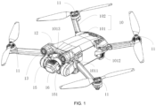
- FIG. 1 illustrates a structural diagram of a UAV in a flying state according to the embodiments of the present application
- FIG. 2 illustrates a top view structural diagram of the UAV shown in FIG. 1
- FIG. 3 illustrates a front view structural diagram of the UAV shown in FIG. 1
- FIG. 4 illustrates a rear view structural diagram of the UAV shown in FIG. 1
- FIG. 5 illustrates a bottom view structural diagram of the UAV shown in FIG. 1
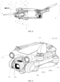
- FIG. 6 illustrates a structural diagram of the UAV shown in FIG. 1 in a hover state
- FIG. 7 illustrates a structural diagram of the UAV shown in FIG. 1 in a backward flight state
- FIG. 1 illustrates a structural diagram of a UAV in a backward flight state
- the UAV can include: a body 10, including a nose F and a tail B opposite to the nose F; a plurality of rotor devices 11, respectively mounted on the body 10 and configured to provide a flight power; and a rear obstacle avoidance sensor 12, mounted on a top part of the body 10 and configured to detect obstacles in a direction of the tail B of the UAV, where the UAV has a backward flight state (as shown in FIG.
- a hover state (as shown in FIG. 6 ) of hovering stably under a windless condition; in the hover state, the body 10 is tilted in a length direction L relative to a horizontal direction H to make the nose F higher than the tail B; a sensing direction of the rear obstacle avoidance sensor 12 has a greater tilt angle relative to the horizontal direction H when the UAV is in the hover state compared to the backward flight state.
- the nose F becomes higher than the tail B; accordingly, the body 10 of the UAV can tilt backward by a certain angle relative to the horizontal direction H to reduce the resistance it encounters. Consequently, this design helps enhance the flight efficiency of the UAV.
- the rear obstacle avoidance sensor 12 by installing the rear obstacle avoidance sensor 12 on the top part of the body 10 and adjusting its sensing direction to have a greater tilt angle relative to the horizontal direction H in the hover state compared to the backward flight state, the position of the rear obstacle avoidance sensor 12 can be optimized concerning the flight and hover attitude of the body 10. This configuration provides a larger obstacle avoidance view angle or a better directional angle for the rear obstacle avoidance sensor. Ultimately, this contributes to improving the overall obstacle avoidance functionality of the UAV and enhances the flight experience thereof.
- the body 10 of the UAV can be tilted backward by a certain angle in the length direction L relative to the horizontal direction H. This allows the rear obstacle avoidance sensor 12 on the top part of the body 10 to better detect obstacles in the direction of the UAV's tail B, obtaining a larger obstacle avoidance view angle or a better directional angle.
- the tilt angle of the obstacle avoidance sensor 12's detection direction relative to the horizontal direction H is smaller than the tilt angle relative to the horizontal direction H when the UAV is in the hover state. That is, in the case where the UAV is in the backward flight state, the angle between the detection direction of the rear obstacle avoidance sensor 12 and the horizontal direction H is relatively small. This is advantageous for the rear obstacle avoidance sensor 12 to better detect obstacles in the UAV's forward direction, thereby obtaining a larger obstacle avoidance view angle or a better directional angle and improving the UAV's obstacle avoidance capabilities.
- the attitude of the body 10 is related to the angle between the sensing direction of the rear obstacle avoidance sensor 12 and the length direction L of the body 10 relative to the horizontal direction H. Therefore, by adjusting the attitude of the body 10, especially the tilt angle of the length direction L of the body 10 relative to the horizontal direction H, the tilt angle between the sensing direction of the rear obstacle avoidance sensor 12 and the horizontal direction H can be adjusted, such that the sensing direction of the rear obstacle avoidance sensor 12 has a greater angle relative to the horizontal direction H when the UAV is in the hover state compared to the backward flight state.
- the tilt angle of the length direction L of the body 10 relative to the horizontal direction H can be a first tilt angle a.
- the tilt angle of the length direction L of the body 10 relative to the horizontal direction H can be a second inclination angle b.
- the length direction L of the body 10 can be the direction connecting the nose F and the tail B of the UAV.
- the horizontal direction H can be a direction parallel to the horizon.
- the sensing direction of the rear obstacle avoidance sensor 12 can be tilted towards a backward and upward direction of the body 10 relative to the horizontal direction H.
- This enables the rear obstacle avoidance sensor 12 located on the top part of the body 10 to have a clear view of the direct horizontal backward direction of the body 10 without being obstructed by the body 10.
- the rear obstacle avoidance sensor 12 since the rear obstacle avoidance sensor 12 is positioned on the top part of the body 10 and tilted towards a backward and upward direction of the body 10 relative to the horizontal direction H in the hover state, it can effectively detect obstacles located in the a backward and upward direction of the body 10.
- the sensing range of the rear obstacle avoidance sensor 12 can be overall above a propeller plane of the rotor device 11 located at the tail B of the UAV.
- This arrangement fully resolves the issue of blind spots caused by the rotor device 11 obstructing the backward and upward view of the rear obstacle avoidance sensor 12, thereby enlarging the detection range of the rear obstacle avoidance sensor 12 and enhancing the overall obstacle avoidance capability of the UAV.
- the UAV may also include a front obstacle avoidance sensor 13, which is installed at the nose F of the central body 101 and is configured to detect obstacles in the direction towards the nose F of the UAV.
- the sensing direction of the front obstacle avoidance sensor 13 can be tilted towards a forward and upward direction of the body 10 relative to the horizontal direction H, enabling it to detect obstacles in the forward and upward direction of the body 10.
- the arrangement of the front obstacle avoidance sensor 13 described herein further increases the UAV's detection range for obstacles, thereby enhancing the overall obstacle avoidance capability of the UAV.
- the UAV may also include a bottom obstacle avoidance sensor 14, which is installed on the bottom part of the central body 101 and is configured to detect obstacles below the boittom part of the UAV.
- the sensing direction of the bottom obstacle avoidance sensor 14 can be tilted towards a forward and downward direction relative to the horizontal direction H, enabling it to detect obstacles in the forward and downward direciton of the UAV.
- This allows the detection range of the bottom obstacle avoidance sensor 14 to overlap with that of the front obstacle avoidance sensor 13 in the forward and downward area relative to the horizontal direction H, reducing detection blind spots and increasing the UAV's overall detection range for obstacles, thereby enhancing its obstacle avoidance capability.
- the front obstacle avoidance sensor 13, the rear obstacle avoidance sensor 12 and the bottom obstacle avoidance sensor 14 can each include a binocular vision module.
- the binocular vision module can employ at least two cameras to observe a target and determine the relative distance between the target and the cameras by triangulation, thus achieving obstacle target detection, i.e., environmental perception.
- obstacle target detection i.e., environmental perception.
- triangulating the distance to any target requires simultaneous observation by at least two cameras.
- at least three sets of binocular vision modules can be provided, covering multiple directions for triangulation detection. This arrangement expands the detection range for obstacles, enhancing the UAV's obstacle avoidance capability and, consequently, improving the UAV flight safety.
- the front obstacle avoidance sensor 13, the rear obstacle avoidance sensor 12 and the bottom obstacle avoidance sensor 14 can also be sensors such as lidar (light detection and ranging) capable of obstacle detection.
- lidar light detection and ranging
- specific details regarding the front obstacle avoidance sensor 13, the rear obstacle avoidance sensor 12 and the bottom obstacle avoidance sensor 14 are not limited.
- Some embodiments of the present application further provide a UAV, which specifically includes: a body 10, including a central body 101 and arms 102 mechanically coupled to the central body 101; and a plurality of rotor devices 11, respectively mounted on the arms 102 and configured to provide a flight power; where the arms 102 may specifically include front arms 1021 and rear arms 1022, the central body 101 may specifically include a first mounting portion 1011 located at a front end and a second mounting portion 1012 located at a rear end, the front arms 1021 are rotationally connected to the first mounting portion 1011, and the rear arms 1022 are rotationally connected to the second mounting portion 1012, the second mounting portion 1012 is higher than the first mounting portion 1011; the UAV has a hover state of stably hovering under a windless condition (as shown in FIG.
- the front arms 1021 and the rear arms 1022 are in an unfolded state relative to the central body 101, and in the storage state, the front arms 1021 and the rear arms 1022 are in a folded state relative to the central body 101; in the hover state, the front arms 1021 are higher than the rear arms 1022, and in the storage state, the front arms 1021 are positioned below the rear arms 1022.
- the movement state of arms 102 is correlated with the attitude of the UAV, thereby facilitating the flight and storage of the UAV.
- the front arms 1021 are higher than the rear arms 1022.
- This arrangement allows the rotor device 11 connected to the front arms 1021 to be correspondingly higher than the rotor device 11 connected to the rear arms 1022. Consequently, this configuration helps reduce the resistance experienced by the UAV, thereby enhancing the UAV's flight efficiency.
- the front arms 1021 can be positioned below the rear arms 1022.
- This arrangement enables the staggered folding of the arms 102, reducing the volume required for storage of the UAV, thus facilitating its portability and transportation.
- the front arms 1021 and the rear arms 1022 due to their staggered positioning in the vertical direction and the unchanged vertical order following the folding, there is no need to consider the folding sequence of the front arms 1021 and the rear arms 1022, so as to improve the folding efficiency and folding flexibility of the arms 102 of the UAV.
- the term “height” specifically refers to the height in the height direction of the UAV.
- both the rear arms 1022 and the front arms 1021 can be attached to the side ends of the central body 101, and the propeller blades 111 of the rotor device 11 can be attached to the central body 101.
- This further reduces the volume of the UAV when it is in the storage state, facilitating its portability and transportation.
- a UAV which specifically includes: a body 10, including a nose F and a tail B opposite to the nose F; a gimbal 15, mounted at a front end of the nose F and specifically including a pitch shaft mechanism; a front obstacle avoidance sensor 12, mounted at the front end of the nose F and positioned above the gimbal 15 for detecting obstacles in a direction of the nose F of the UAV; and a camera 16, connected to the nose F of the body 10 via the gimbal 15 and configured to change a pitch angle thereof via the pitch shaft mechanism so as to allow the camera 16 to capture images above or below the body 10; where the nose F has an avoidance portion 1013 above the camera 16, the avoidance portion 1013 has a recess corresponding to the camera 16, the front obstacle avoidance sensor 13 is located on the avoidance portion 1013; the UAV has a hover state of stably hovering under a windless condition, and in the hover state, the body 10 is tilted in a length direction L relative to a horizontal
- the camera 16 due to the camera 16 being connected to the nose F of the body 10 via the gimbal 15, the camera 16 is able to change the pitch angle thereof via the pitch shaft mechanism.
- an avoidance portion 1013 is provided above the camera 16 on the nose F.
- the camera 16, driven by the gimbal 15 can capture images through the recess of the avoidance portion 1013, thereby improving the camera 16's pitch shooting range.
- the camera 16's pitch angle shooting range is expanded, thereby improving the camera 16's aerial photography performance.
- the pitch shaft mechanism of the gimbal 15 can drive the camera 16 to change its pitch angle, aiming above or below the body 10 for shooting.
- the camera 16 is directed above the body 10 for shooting, due to the avoidance portion 1013 being arranged above the nose F of the body 10, the existence of the avoidance portion 1013 can avoid the obstruction caused by the body 10 to the camera 16, expanding the pitch shooting range of the camera 16. This is beneficial for obtaining better aerial photography effects.
- the flight state can also include a forward flight state, where the UAV flies in the direction of the nose F.
- the length direction L of the body 10 is substentially parallel to the horizontal direction H, reducing the frontal area of the body 10 and consequently minimizing the resistance experienced by the body 10 during the forward flight. This enhances the flight efficiency of the UAV.
- the forward flight state is the primary operating state of the UAV
- reducing the resistance experienced by the body 10 during this state can significantly decrease the UAV's energy consumption. This, in turn, improves the UAV's flight efficiency and enhances the user experience with the UAV.
- the UAV in the forward flight state, the UAV essentially flies at a target flight speed.
- the first tilt angle a of the length direction L of the body 10 relative to the horizontal direction H is related to the target flight speed. This allows for the adjustment of the first tilt angle a of the body 10 relative to the horizontal direction H based on the target flight speed during the hover state. Consequently, when the UAV flies forward at the target flight speed, the frontal area of the body 10 is minimized, thus the resistance experienced by body 10 is minimized. Since the UAV primarily flies at the target flight speed during forward flight, this greatly reduces the UAV's resistance during forward flight and decreases its energy consumption.
- the target flight speed can be set according to specific circumstances.
- the target flight speed could be 10 meters per second, 12 meters per second, 15 meters per second, or any other value deemed appropriate.
- the embodiments of the present application do not impose specific limitations on the exact value of the target flight speed.
- the first tilt angle a is related to a target coefficient, where the target coefficient is associated with the size and shape of the body 10.
- the target coefficient is associated with the size and shape of the body 10. This implies that the value of the first tilt angle a needs to take into account the shape and size of the body 10, and the target coefficient can be determined based on the shape and size of the body 10.
- the target coefficient can be used to assess the influence of the shape and size of the body 10 on the first tilt angle a.
- the setting of the first tilt angle a takes into account both the target flight speed and the target coefficient, comprehensively evaluating the impact of the UAV's propulsion system and overall configuration. Therefore, the setting of the first tilt angle a is considered objective and scientific. This approach further reduces the UAV's energy consumption and improves its flight efficiency.
- the first tilt angle a is positively correlated with both the target coefficient and the target flight speed. That is, the larger the target flight speed, the larger the first tilt angle a correspondingly; the greater the target coefficient, the larger the first tilt angle a correspondingly. This is beneficial for calculating the first tilt angle a.
- the following provides a calculation formula for calculating the first tilt angle a: a ⁇ k * v where a represents the first tilt angle a, k represents the target coefficient, the target coefficient is related to the shape and size of the body 10, and v represents the target flight speed when the UAV is in the forward flight state.
- the tilt angle of the length direction L of the body 10 relative to the horizontal direction H is between 5 degrees and 25 degrees, which is beneficial for the hover stability of the UAV when it is in the hover state.
- the first tilt angle a can be set according to actual circumstances.
- the first tilt angle a can be 10 degrees, 15 degrees, or 18 degrees, etc.
- the embodiments of the application do not limit the specific value of the first tilt angle a.
- the flight state can also include a forward flight state in which the UAV flies in the direction of nose F, and a backward flight state in which the UAV flies in the direction of the tail B.
- a first optical axis D1 of the front obstacle avoidance sensor 13 can be tilted forward and downward relative to the horizontal direction H, in order to detect obstacles in the forward and downward direction relative to the horizontal direction H
- a second optical axis D2 of the bottom obstacle avoidance sensor 14 can be tilted backward and downward relative to the horizontal direction H, in order to detect obstacles in the backward and downward direction relative to the horizontal direction H
- a third optical axis D3 of the rear obstacle avoidance sensor 12 can be tilted backward and upward relative to the horizontal direction H, in order to detect obstacles in the backward and upward direction relative to the horizontal direction H.
- the first optical axis D1 of the front obstacle avoidance sensor 13 can be tilted in the forward and upward direction relative to the horizontal direction H, in order to detect obstacles in the forward and upward direction relative to the horizontal direction H;
- the second optical axis D2 of the bottom obstacle avoidance sensor 14 can be tilted in the forward and downward direction relative to the horizontal direction H, in order to detect obstacles in the forward and downward direction relative to the horizontal direction H;
- the third optical axis D3 of the rear obstacle avoidance sensor 12 can be tilted in the backward direction relative to the horizontal direction H, in order to detect obstacles in the backward direction relative to the horizontal direction H.
- the third optical axis D3 of the rear obstacle avoidance sensor 12 can be oriented to be substantially parallel to the horizontal direction H.
- This configuration ensures that, when the UAV is in the backward flight state, the angle between the sensing direction of the rear obstacle avoidance sensor 12 and the horizontal direction H is relatively small. Consequently, this facilitates better detection of obstacles in the UAV's forward direction by the rear obstacle avoidance sensor 12, allowing for a larger obstacle avoidance field of view or better directional angles, thus enhancing the UAV's obstacle avoidance capabilities.
- the front obstacle avoidance sensor 13 has a first perception coverage area S1
- the bottom obstacle avoidance sensor 14 has a second perception coverage area S2
- the rear obstacle avoidance sensor 12 has a third perception coverage area S3.
- the second optical axis D2 of the bottom obstacle avoidance sensor 14 is tiled in a forward and downward direction relative to the length direction L of the central body 101, such that the second perception coverage area S2 partially overlaps with at least a portion of the first perception coverage area S1.
- the second perception coverage area S2 since the second perception coverage area S2 partially overlaps with at least a portion of the first perception coverage area S1, it helps reduce the UAV's obstacle detection blind spots, enabling omnidirectional obstacle avoidance detection. This is beneficial for enhancing the UAV's obstacle avoidance capabilities.
- the first perception coverage area S1 includes a first upper boundary S11 and a first lower boundary S12;
- the second perception coverage area S2 includes a first front boundary S21 and a first rear boundary S22.
- the first lower boundary S12 partially overlaps with the first front boundary S21 to avoid potential blind spots in obstacle detection between the front obstacle avoidance sensor 13 and the bottom obstacle avoidance sensor 14 as much as possible. This arrangement enables c omnidirectional obstacle avoidance detection, thereby enhancing the UAV's obstacle avoidance capabilities.
- the overlapping angle between the first lower boundary S12 and the first front boundary S21 is less than or equal to 5 degrees. This not only reduces potential blind spots in obstacle detection between the front obstacle avoidance sensor 13 and the bottom obstacle avoidance sensor 14, but also minimizes the impact of the overlap between the first lower boundary S12 and the first front boundary S21 on the overall detection perspective of the UAV. It is beneficial for enhancing the overall obstacle avoidance capability of the UAV.
- the third optical axis D3 of the rear obstacle avoidance sensor 12 is tilted in an upward direction relative to the length direction L of the central body 101. This allows the rear obstacle avoidance sensor 12 located on the top part of body 10 to have a better view in the direct horizontal backward direction of the body 10 without being obstructed by the body 10. Moreover, since the rear obstacle avoidance sensor 12 is positioned on the top part of the body 10, its sensing range can be overall higher than the propeller plane of the rotor device 11 located at the tail B.
- the angle at which the third optical axis D3 is tilted upward relative to the horizontal direction H is less than or equal to 30 degrees. This ensures that regardless of the UAV's attitude, the sensing direction of the rear obstacle avoidance sensor 12 can always be oriented towards the tail B of the UAV.
- the angle at which the third optical axis D3 is tilted upwards relative to the horizontal direction H can be adjusted according to specific circumstances. For example, it could be set to 5 degrees, 7 degrees, or 10 degrees, etc.
- the embodiments of the present application does not limit a specific tilt angle of the third optical axis D3 relative to the horizontal direction H.
- the first optical axis D1 of the front obstacle avoidance sensor 13 is oriented to be substantially parallel to the length direction L of the central body 101, allowing the front obstacle avoidance sensor 13 to continuously detect obstacles in the direction of the UAV's nose F.
- the installation of the front obstacle avoidance sensor 13 can be referenced to the horizontal direction H, thereby improving the accuracy and efficiency of its installation.
- the rear obstacle avoidance sensor 12 can be positioned close to the front obstacle avoidance sensor 13.
- the front obstacle avoidance sensor 13 is mounted at the nose F of the body 10
- positioning the rear obstacle avoidance sensor 12 close to the front obstacle avoidance sensor 13 allows the rear obstacle avoidance sensor 12 to be as close as possible to the nose F of the body 10. This minimizes the obstruction caused by the rotor device 11 in the direction of tail B of the body 10, thereby increasing the detection range of the rear obstacle avoidance sensor 12.
- both the rear obstacle avoidance sensor 12 and the front obstacle avoidance sensor 13 are mounted on the top part of the body 10, and the distance between the rear obstacle avoidance sensor 12 and the front obstacle avoidance sensor 13 is less than a first threshold value. This ensures that the rear obstacle avoidance sensor 12 is positioned as close as possible to the front obstacle avoidance sensor 13.
- the specific value of the first threshold value can be adjusted according to actual circumstances.
- the first threshold value could be set to 5 millimeters, 8 millimeters, or 20 millimeters, etc.
- the embodiments of the present application does not limit a specific value for the first threshold value.
- the body 10 may also be equipped with a support 103, on which both the front obstacle avoidance sensor 13 and the rear obstacle avoidance sensor 12 are mounted.
- This arrangement allows the front obstacle avoidance sensor 13 and the rear obstacle avoidance sensor 12 to share a single support 103, reducing the number of support 103 required for mounting obstacle avoidance sensors of the UAV. It also minimizes the space occupied by the support 103 on the body 10, thereby facilitating the overall component layout of the body 10.
- the cross-sectional shape of the propeller blade 111 along the rotation direction of the rotor device 11 can be arc-shaped, with a side closer to the forward rotation direction being lower than a side farther away from the forward rotation direction, in order to reduce the wind resistance of the propeller blade 111 during rotation and improve the rotation efficiency of the rotor device 11.
- An arc-shaped portion 104 is provided at a top part of a side end of the central body 101.
- the propeller blades 111 on the rear arms 1022 are attached to the arc-shaped portion 104 so that the propeller blade 111 on the rear arms 1022 fully attach to the arc-shaped portion 104 of the central body 101, reducing the size of the UAV after folding, which can facilitate the carrying and transportation of the UAV.
- the front arms 1021 may specifically include a left front arm 10211 and a right front arm 10212, with the rotor device 11 installed on the left front arm 10211 being the left front rotor device 112, and the rotor device 11 installed on the right front arm 10212 being the right front rotor device 113;
- the rear arms 1022 may specifically include a left rear arm 10221 and a right rear arm 10222, with the rotor device 11 installed on the left rear arm 10221 being the left rear rotor device 114, and the rotor device 11 installed on the right rear arm 10222 being the right rear rotor device 115.
- the rotation direction of the left front rotor device 112 and that of the right rear rotor device 115 are both a first rotation direction
- the rotation direction of the right front rotor device 113 and that of the left rear rotor device 114 are both a second rotation direction, where the second rotation direction is opposite to the first rotation direction.
- the rotation directions of the left front rotor device 112 and the right rear rotor device 115 are the same, the rotation directions of the right front rotor device 113 and the left rear rotor device 114 are the same, and the rotation directions of the left front rotor device 112 and the right front rotor device 113 are opposite, it allows for the left front rotor device 112, the right rear rotor device 115, the right front rotor device 113 and the left rear rotor device 114 to collectively provide lift for the UAV.
- first rotation direction can be clockwise, and the second rotation direction can be counterclockwise.
- first rotation direction can be counterclockwise, and the second rotation direction can be clockwise.
- the embodiments of this application do not specifically limit the first rotation direction and the second rotation direction.
- the propeller blade 111 on the left rear rotor device 114 is attached to the arc-shaped portion 104 at the top part on the left side of the central body 101, while the propeller blade 111 on the right rear rotor device 115 is attached to the arc-shaped portion 104 at the top part on the right side of the central body 101.
- the first rotation direction may be clockwise, meaning that the rotation direction of the right rear rotor device 115 is clockwise. Consequently, in the clockwise direction, the cross-sectional shape of the propeller blade 111 on the right rear rotor device 115 is arc-shaped with a lower height on the side closer to the forward direction. In this way, when the propeller blade 111 on the right rear rotor device 115 is folded and stored at the top part on the right side of the central body 101, the cross-sectional shape of the propeller blade 111 on the right rear rotor device 115 can fit to the shape of the arc-shaped portion 104 at the top part on the right side of the central body 101. This facilitates improving the fit between the propeller blade 111 on the right rear rotor device 115 and the arc-shaped portion 104 at the top part on the right side of the central body 101, further reducing the volume after the propeller blade 111 is folded and stored.
- the second rotation direction may be counterclockwise, meaning that the rotation direction of the left rear rotor device 114 is counterclockwise. Consequently, in the counterclockwise direction, the cross-sectional shape of the propeller blade 111 on the left rear rotor device 114 is arc-shaped with a lower height on the side closer to the forward direction. In this way, when the propeller blade 111 on the left rear rotor device 114 is folded and stored at the top part on the left side of the central body 101, the cross-sectional shape of the propeller blade 111 on the left rear rotor device 114 can match the shape of the arc-shaped portion 104 at the top part on the left side of the central body 101. This facilitates improving the fit between the propeller blade 111 on the left rear rotor device 114 and the arc-shaped portion 104 at the top part on the left side of the central body 101, further reducing the volume after the propeller blade 111 is folded and stored.
- left refers to the left side of the UAV when facing the nose F direction.
- right refers to the left side of the UAV when facing the nose F direction.
- the rear arms 1022 fold along a side of the center body 101 towards the nose F direction, and the front arms 1021 fold along a side of the center body 101 towards the tail B direction, in order to further reduce interference between the front arms 1021 and the rear arms 1022 during the folding process.
- the rear arms 1022 can be folded first along the side of the center body 101 towards the nose F direction, and then the front arms 1021 can be folded along the side of the center body 101 towards the tail B direction, so as o avoid the landing gear of the front arms 1021 affecting the folding of the rear arms 1022.
- the rear arms 1022 are higher than the front arms 1021, the rear arms 1022 and the front arms 1021 can achieve staggered folding vertically. Therefore, in practical applications, there is no need to consider the folding sequence of the front arms 1021 and the rear arms 1022, thereby greatly improving the folding flexibility of the arms 102.
- the UAV may also include a landing gear; the bottom part of the center body 101 is provided with a landing gear connection portion 105; the landing gear connection portion 105 specifically includes two front landing gear connection portions 1051 and two rear landing gear connection portions 1052.
- the propeller blades 111 on the front arms 1021 can be retracted between the two front landing gear connection portions 1051. In this way, on the one hand, it is convenient to store the propeller blades 111 on the front arms 1021 at the bottom part of the center body 101, further reducing the volume after the propeller blades 111 are folded and stored.
- the propeller blades 111 on the front arms 1021 can also be limited by the two front landing gear connection portions 1051, preventing the propeller blades 111 on the front arms 1021 from disengaging from the bottom part of the center body 101, thereby improving the reliability of storing the propeller blades 111.
- the rear landing gear connection portions 1052 can be the rotor mounting portion on the front arms 1021, so as to avoid separately setting the rear landing gear connection portions 1052 at the bottom part of the center body 101.
- the rotor mounting portions on the front arms 1021 for mounting the rotor device 11 can correspondingly fold toward the tail B direction and be close to the bottom part of the center body 101.
- the rotor mounting portions on the front arms 1021 can serve as the rear landing gear connection portions 1052, so as to avoid the additional operation of separately setting the rear landing gear connection portions 1052 at the bottom part of the center body 101, simplifying the structure of the center body 101, and being beneficial to the layout of components at the bottom part of the center body 101.
- the rear landing gear connection portions 1052 can be protruding portions extending from the center body 101, so as to avoid the additional operation of separately setting the rear landing gear connection portions1052 at the bottom part of the center body 101, simplifying the structure of the center body 101, and being beneficial to the layout of components at the bottom part of the center body 101.
- the bottom part of the center body 101 is also provided with a battery case 106, and the protruding portion can be a part of the battery case 106.
- the UAV usually needs a battery to drive the rotor devices 11 to rotate, so as to provide flight power for the UAV.
- a battery case 106 typically needs to be provided outside the battery. Since the volume of the battery is relatively large and usually needs to be arranged at the bottom part of the center body 101, the battery case 106 is typically arranged at the bottom part of the center body 101 and protrudes from the bottom part of the center body 101.
- the battery case 106 since the battery case 106 protrudes from the bottom part of the center body 101, the battery case 106 can serve as the rear landing gear connection portion 1052, so as to avoid the additional operation of separately setting the rear landing gear connection portion 1052 at the bottom part of the center body 101, simplifying the structure of the center body 101, and being beneficial to the layout of components at the bottom part of the center body 101.
- the rotation axis 116 of the rotor device 11 is tilted relative to the height direction of the center body 101.
- the rotor device 11 can generate an upward lift force F along the rotation axis 116. Since the rotation axis 116 is tilted relative to the height direction of the center body 101, the lift force F can be decomposed into a horizontal component force F1 and a vertical component force F2.
- the vertical component force F2 can provide the flight lift for the UAV
- the horizontal component force F1 can provide the yaw force for the UAV, thereby achieving a better yaw control effect.
- the rotation axis 116 of rotor device 11 is tilted outward relative to the height direction of the central body 101. This allows the horizontal component force F1 to correspondingly point towards a direction away from the central body 101, achieving sustained and stable yaw force, thus beneficial for further enhancing the yaw control effectiveness of the UAV.
- the tilting of the rotation axis 116 of the rotor device 11 outward relative to the height direction the central body 101 can specifically include: tilting the rotation axis 116 towards the nose direction F relative to the central body 101, tilting it towards the tail B direction, or tilting it to the left or right sides.
- the embodiments of this application do not limit the tilting manner of the rotation axis 116.
- the top part of the rotation axis 116 of the rotor device 11 can be tilted towards both sides of the central body 101, i.e., the rotation axis 116 of the left front rotor device 112 and that of the left rear rotor device 114 are tilted towards the left side of the central body 101, and the rotation axis 116 of the right front rotor device 113 and that of the right-rear rotor device 115 are tilted towards the right side of the central body 101.
- the lift F direction of the propeller blade 111 of the rotor device 11 is tilted towards both left and right sides away from the central body 101.
- the horizontal component force F1 is entirely in the left and right direction. In this way, the stability of the yaw force can be further improved, and the impact of the tilted rotation axis 116 on the attitude of the UAV can be reduced. Therefore, it is possible to enhance the flight stability of the UAV while achieving yaw control.
- the tilt angle range of the rotation axis 116 relative to the vertical direction of the central body 101 may be from 5 degrees to 7 degrees, in order to achieve better yaw control torque while reducing the impact of the tilted rotation axis 116 on the vertical component force F2, thus balancing both effective yaw control and flight stability.
- the camera 16 can be movably connected to the central body 101 via the gimbal 15.
- the gimbal 15 can include a pitch shaft 151, a yaw shaft, and a roll shaft, and the camera 16 can move around the pitch shaft 151, the yaw shaft, and the roll shaft respectively.
- the shooting range of the camera 16 can be adjusted, thereby improving the aerial photography effect of the camera 16.
- the gimbal 15 and the camera 16 are both connected to the front end of the central body 101, and the avoidance portion 1013 can be arranged on the top part of the central body 101 to at least partially avoid the gimbal 15 and the camera 16. This allows the camera 16 to be positioned in a recess of the avoidance portion 1013 when the gimbal 15 lifts the camera 16 upward for shooting, thereby increasing the pitch shooting range of the camera 16.
- the front end of the central body 101 may also be equipped with two protrusions extending towards the direction of the nose F, with a gap set between the two protrusions.
- One end of the pitch shaft 151 is suspended from one of the protrusions, while the other end of the pitch shaft 151 is suspended from the other protrusion.
- the gimbal 15 and the camera 16 are both located between these two protrusions.
- This arrangement facilitates the respective connection of the pitch shaft 151 to the central body 101 at both ends thereof, thus enhancing the reliability of the connection of the pitch shaft 151 to the central body 101.
- the support reliability of the pitch shaft 151 for the camera 16 can also be improved. Consequently, the stability of the shooting process during the pitch adjustment of the camera 16 can be improved.
- the pitch shaft 151 can be a "U"-shaped pitch shaft, where the two ends of the "U”-shaped pitch shaft are respectively suspended from the protrusions.
- An arc-shaped section of the "U"-shaped pitch shaft can be used to form an accommodating space for accommodating the camera 16.
- the "U"-shaped pitch shaft can effectively avoid interference with the camera 16, allowing the camera 16 to rotate within the housing space of the "U"-shaped pitch shaft, thus avoiding interference between the camera 16 and the central body 101. Consequently, the maneuverability of the camera 16 can be improved.
- the UAV in the embodiments of the present application may have the following advantages.
- the nose becomes higher than the tail; accordingly, the body of the UAV can tilt backward by a certain angle relative to the horizontal direction to reduce the resistance it encounters. Consequently, this design helps enhance the flight efficiency of the UAV.
- the rear obstacle avoidance sensor can be installed on the top part of the body and adjusting its sensing direction to have a greater tilt angle relative to the horizontal direction in the hover state compared to the backward flight state, the position of the rear obstacle avoidance sensor can be optimized concerning the flight and hover attitude of the body. This configuration provides a larger obstacle avoidance view angle or a better directional angle for the rear obstacle avoidance sensor. Ultimately, this contributes to improving the overall obstacle avoidance functionality of the UAV and enhances the flight experience thereof.
- the device embodiments described above are merely illustrative.
- the units described as separate components can be physically separate or not.
- Components shown as units can be physical units or not, that is, they can be located in one place or distributed across multiple network units. It is possible to select some or all modules as needed to achieve the objects of the embodiments of the present application. A person skilled in the art can understand and implement the present application without any creative efforts.
- an embodiment refers to that particular features, structures, or features described in connection with the embodiment(s) are included in at least one embodiment of the present application.
- examples of the word “in one embodiment” herein do not necessarily all refer to the same embodiment.
- any reference symbols placed in parentheses should not be construed as limiting the claims.
- the word “comprising” does not exclude the presence of elements or steps not listed in the claims.
- the word “a” or “an” preceding an element does not exclude the presence of multiple such elements.
- the present application may be implemented with hardware including several different components and/or with a computer programmed appropriately.
- some of the units may be embodied by the same hardware item.
- the use of the terms “first,” “second,” “third,” etc., does not imply any particular order, and these terms can be interpreted as titles.
Landscapes
- Engineering & Computer Science (AREA)
- Mechanical Engineering (AREA)
- Aviation & Aerospace Engineering (AREA)
- Remote Sensing (AREA)
- Chemical & Material Sciences (AREA)
- Combustion & Propulsion (AREA)
- Microelectronics & Electronic Packaging (AREA)
- Control Of Position, Course, Altitude, Or Attitude Of Moving Bodies (AREA)
- Toys (AREA)
Abstract
Description
- This application relates to the technical field of aircrafts, and in particular to an unmanned aerial vehicle.
- As users increasingly pursue the ultimate user experience, their demands for the performance of unmanned aerial vehicles (UAVs) are also rising. For instance, to enhance the safety of UAVs, an increasing number of UAVs are incorporated with the visual obstacle avoidance technology. To facilitate portability, transportation, and storage, more and more UAVs are adopting the foldable arm technology. Additionally, to achieve aerial photography, a growing number of UAVs are integrated with the gimbal camera aerial photography technology.
- In the existing visual obstacle avoidance technology, the triangulation function of binocular cameras is commonly employed to detect obstacles, achieving environmental perception. However, the current range of detection for existing binocular cameras is limited, and the field of view of these cameras is prone to being obstructed by robotic arms or propellers, thereby affecting the effectiveness of visual obstacle avoidance. Present UAVs, especially those with foldable arms, still maintain a relatively large volume, impacting the convenience of carrying, transporting, and storing the UAVs. In the aerial photography scenarios of current UAVs, there is a general requirement for the gimbal camera to capture a maximized range to meet various aerial photography needs.
- To address the limitations in the visual obstacle avoidance effectiveness, the retained large volume after arm folding, and constrained aerial photography effects in existing technologies, some embodiments of this application introduces an unmanned aerial vehicle (UAV) as follows.
- In a first aspect, some embodiments of this application provide a UAV, including:
- a body, including a nose and a tail opposite to the nose;
- a plurality of rotor devices, respectively mounted on the body and configured to provide a flight power; and
- a rear obstacle avoidance sensor, mounted on a top part of the body and configured to detect obstacles in a direction towards the tail of the UAV,
- where the UAV has a backward flight state of flying in the direction of the tail and a hover state of hovering stably under a windless condition,
- in the hover state, the body is tilted in a length direction relative to a horizontal direction to make the nose higher than the tail, and
- a sensing direction of the rear obstacle avoidance sensor has a greater tilt angle relative to the horizontal direction when the UAV is in the hover state compared to the backward flight state.
- In some embodiments of this application, as the body is tilted in the length direction relative to the horizontal direction in the hover state, the nose becomes higher than the tail; accordingly, the body of the UAV can tilt backward by a certain angle relative to the horizontal direction to reduce the resistance it encounters. Consequently, this design helps enhance the flight efficiency of the UAV. Additionally, by installing the rear obstacle avoidance sensor on the top part of the body and adjusting its sensing direction to have a greater tilt angle relative to the horizontal direction in the hover state compared to the backward flight state, the position of the rear obstacle avoidance sensor can be optimized concerning the flight and hover attitude of the body. This configuration provides a larger obstacle avoidance view angle or a better directional angle for the rear obstacle avoidance sensor. Ultimately, this contributes to improving the overall obstacle avoidance functionality of the UAV and enhances the flight experience thereof.
- In a second aspect, some embodiments of this application disclose a UAV, including:
- a body, including a central body and arms mechanically coupled to the central body; and
- a plurality of rotor devices, respectively mounted on the arms and configured to provide a flight power;
- where the arms include front arms and rear arms, the central body includes a first mounting portion located at a front end and a second mounting portion located at a rear end, the front arms are rotationally connected to the first mounting portion, and the rear arms are rotationally connected to the second mounting portion, the second mounting portion is higher than the first mounting portion;
- the UAV has a hover state of stably hovering under a windless condition and a storage state for easy portability, in the hover state, the front arms and the rear arms are in an unfolded state relative to the central body, and in the storage state, the front arms and the rear arms are in a folded state relative to the central body;
- in the hover state, the front arms are higher than the rear arms, and in the storage state, the front arms are positioned below the rear arms.
- According to the exemplary embodiments of the present application, due to the higher positioning of the front arms compared to the rear arms in the hover state of the UAV and the lower positioning the front arms compared to the rear arms in the storage state, the movement state of arms is correlated with the attitude of the UAV, thereby facilitating the flight and storage of the UAV.
- In a third aspect, some embodiments of this application further disclose a UAV, including:
- a body, including a nose and a tail opposite to the nose;
- a gimbal, mounted at a front end of the nose and including a pitch shaft mechanism;
- a front obstacle avoidance sensor, mounted at the front end of the nose and positioned above the gimbal; and
- a camera, connected to the nose of the body via the gimbal and configured to change a pitch angle thereof via the pitch shaft mechanism so as to allow the camera to capture images above or below the body;
- where the nose has an avoidance portion above the camera, the avoidance portion has a recess corresponding to the camera, the front obstacle avoidance sensor is located on the avoidance portion;
- the UAV has a hover state of stably hovering under a windless condition, and in the hover state, the body is tilted in a length direction relative to a horizontal direction to make the nose higher than the tail, so as to allow the camera to capture images through the recess of the avoidance portion.
- In some exemplary embodiment of this application, due to the camera being connected to the body's nose via the gimbal, the camera is able to change the pitch angle thereof via the pitch shaft mechanism. In addition, an avoidance portion is provided above the camera on the nose. In the hover state, with the body tilted in the length direction relative to the horizontal direction and the nose being higher than the tail, the camera, driven by the gimbal, can capture images through the recess of the avoidance portion, thereby improving the camera's pitch shooting range. In this way, by coordinating the gimbal's setting manner with the UAV's state, the camera's pitch angle shooting range is expanded, thereby improving the camera's aerial photography performance.
- The above description is only an overview of the technical solutions in this application. To gain a clearer understanding of the technical means disclosed in this application and to implement them based on the content of the description, specific embodiments of the application are provided below to make the above and other objects, features, and advantages of this application more apparent and understandable.
- In order to provide a clearer description of the technical solutions in the embodiments of this application or in the existing technologies, a brief introduction to the drawings required in the description of the embodiments or the existing technologies will be given below. It is evident that the drawings presented in the following description are some embodiments of this application, and a person skilled in the art can obtain additional drawings based on these drawings without exerting inventive efforts.
-
FIG. 1 schematically illustrates a structural diagram of a UAV in a flying state according to the embodiments of the present application; -
FIG. 2 schematically illustrates a top view structural diagram of the UAV shown inFIG. 1 ; -
FIG. 3 schematically illustrates a front view structural diagram of the UAV shown inFIG. 1 ; -
FIG. 4 schematically illustrates a rear view structural diagram of the UAV shown inFIG. 1 ; -
FIG. 5 schematically illustrates a bottom view structural diagram of the UAV shown inFIG. 1 ; -
FIG. 6 schematically illustrates a structural diagram of the UAV shown inFIG. 1 in a hover state; -
FIG. 7 schematically illustrates a structural diagram of the UAV shown inFIG. 1 in a backward flight state; -
FIG. 8 schematically illustrates a structural diagram of the UAV shown inFIG. 1 in a forward flight state; -
FIG. 9 schematically illustrates a structural diagram of the UAV shown inFIG. 1 in a folded state; -
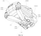
FIG. 10 schematically illustrates another structural diagram of the UAV shown inFIG. 1 in a folded state. - 10 - body, 101 - central body, 1011 - first mounting portion, 1012 - second mounting portion, 1013 - avoidance portion, 102 - arm, 1021 - front arm, 10211 - left front arm, 10212 - right front arm, 1022 - rear arm, 10221 - left rear arm, 10222 - right rear arm, 103 - support, 104 - arc-shaped portion, 105 - landing gear connection portion, 1051 - front landing gear connection portion, 1052 - rear landing gear connection portion, 106 - battery case, 11 - rotor device, 111 - propeller blade, 112 - left front rotor device, 113 - right front rotor device, 114 - left rear rotor device, 115 - right rear rotor device, 116 - rotation axis, 12 - rear obstacle avoidance sensor, 13 - front obstacle avoidance sensor, 14 - bottom obstacle avoidance sensor, 15 - gimbal, 151 - pitch shaft, 16 - camera, L - length direction, H - horizontal direction, a - first tilt angle, b - second tilt angle, F - nose, B - tail, D1 - first optical axis, D2 - second optical axis, D3 - third optical axis, S1 - first perception coverage area, S11 - first upper boundary, S12 - first lower boundary, S2 - second perception coverage area, S21 - second front boundary, S22 - second rear boundary, S3 - third perception coverage area, c - overlapping angle.
- To provide a clearer and full description of the technical solutions in the embodiments of this application and to better illustrate the purposes and advantages, the following detailed description will be combined with the accompanying drawings. It is evident that the described embodiments are part of the embodiments of this application, not all of them. All other embodiments obtained by a person skilled in the art based on the embodiments in this application without creative efforts fall within the scope of protection of this application.
- The terms "first," "second," etc., as used in the description and claims of this application, can include or implicitly include one or more features unless explicitly stated otherwise. In the description of this application, unless otherwise specified, the term "a plurality of' means two or more. Additionally, the use of "and/or" in the description and claims indicates at least one of the connected elements, and the character "/" generally implies an "or" relationship between the associated elements.
- It should be understood that in the description of this application, terms such as "center," "longitudinal," "lateral," "length," "width," "thickness," "upper," "lower," "front," "rear," "left," "right," "vertical," "horizontal," "top," "bottom," "inner," "outer," "clockwise," "counterclockwise," "axial," "radial," "circumferential," and the like, indicating orientation or positional relationships, are based on the orientation or positional relationships shown in the drawings. These terms are used for ease of description and to simplify the disclosure, they do not necessarily imply that the device or elements must have a particular orientation, be constructed, or operated in a specific orientation. Therefore, these terms should not be construed as limiting the scope of this application.
- In the description of this application, it should be noted that, unless explicitly specified and limited, terms such as "mounting," "connecting," and "linking" should be broadly interpreted. For example, this can include fixed connections, detachable connections, or integral connections; mechanical connections or electrical connections; direct connections or indirect connections via an intermediate medium; and communication within two parts. For a person skilled in the art, the specific meanings of these terms in this application can be understood based on the specific circumstances.
- The embodiments of this application provide a UAV that can be used as various unmanned aerial vehicles requiring folding, such as aerial photography UAVs, agricultural crop protection UAVs, surveying UAVs, and the like. In the embodiments of this application, the UAV is exemplified as an agricultural crop protection UAV for illustration.
- Reference can be made to the following figures.
FIG. 1 illustrates a structural diagram of a UAV in a flying state according to the embodiments of the present application;FIG. 2 illustrates a top view structural diagram of the UAV shown inFIG. 1 ;FIG. 3 illustrates a front view structural diagram of the UAV shown inFIG. 1 ;FIG. 4 illustrates a rear view structural diagram of the UAV shown inFIG. 1 ;FIG. 5 illustrates a bottom view structural diagram of the UAV shown inFIG. 1 ;FIG. 6 illustrates a structural diagram of the UAV shown inFIG. 1 in a hover state;FIG. 7 illustrates a structural diagram of the UAV shown inFIG. 1 in a backward flight state;FIG. 8 illustrates a structural diagram of the UAV shown inFIG. 1 in a forward flight state;FIG. 9 illustrates a structural diagram of the UAV shown inFIG. 1 in a folded state; andFIG. 10 illustrates another structural diagram of the UAV shown inFIG. 1 in a folded state. Specifically, the UAV can include: abody 10, including a nose F and a tail B opposite to the nose F; a plurality ofrotor devices 11, respectively mounted on thebody 10 and configured to provide a flight power; and a rearobstacle avoidance sensor 12, mounted on a top part of thebody 10 and configured to detect obstacles in a direction of the tail B of the UAV, where the UAV has a backward flight state (as shown inFIG. 7 ) of flying in the direction of the tail B (as shown in the direction pointed by the broad arrow inFIG. 7 ) and a hover state (as shown inFIG. 6 ) of hovering stably under a windless condition; in the hover state, thebody 10 is tilted in a length direction L relative to a horizontal direction H to make the nose F higher than the tail B; a sensing direction of the rearobstacle avoidance sensor 12 has a greater tilt angle relative to the horizontal direction H when the UAV is in the hover state compared to the backward flight state. - In some embodiments of this application, as the
body 10 is tilted in the length direction L relative to the horizontal direction H in the hover state, the nose F becomes higher than the tail B; accordingly, thebody 10 of the UAV can tilt backward by a certain angle relative to the horizontal direction H to reduce the resistance it encounters. Consequently, this design helps enhance the flight efficiency of the UAV. Additionally, by installing the rearobstacle avoidance sensor 12 on the top part of thebody 10 and adjusting its sensing direction to have a greater tilt angle relative to the horizontal direction H in the hover state compared to the backward flight state, the position of the rearobstacle avoidance sensor 12 can be optimized concerning the flight and hover attitude of thebody 10. This configuration provides a larger obstacle avoidance view angle or a better directional angle for the rear obstacle avoidance sensor. Ultimately, this contributes to improving the overall obstacle avoidance functionality of the UAV and enhances the flight experience thereof. - As shown in
FIG. 6 , due to the installation of the rearobstacle avoidance sensor 12 on the top part of thebody 10, when the UAV is in the hover state, thebody 10 of the UAV can be tilted backward by a certain angle in the length direction L relative to the horizontal direction H. This allows the rearobstacle avoidance sensor 12 on the top part of thebody 10 to better detect obstacles in the direction of the UAV's tail B, obtaining a larger obstacle avoidance view angle or a better directional angle. - As shown in
FIG. 7 , in the case where the UAV is in the backward flight state, the tilt angle of theobstacle avoidance sensor 12's detection direction relative to the horizontal direction H is smaller than the tilt angle relative to the horizontal direction H when the UAV is in the hover state. That is, in the case where the UAV is in the backward flight state, the angle between the detection direction of the rearobstacle avoidance sensor 12 and the horizontal direction H is relatively small. This is advantageous for the rearobstacle avoidance sensor 12 to better detect obstacles in the UAV's forward direction, thereby obtaining a larger obstacle avoidance view angle or a better directional angle and improving the UAV's obstacle avoidance capabilities. - In practical applications, the attitude of the
body 10 is related to the angle between the sensing direction of the rearobstacle avoidance sensor 12 and the length direction L of thebody 10 relative to the horizontal direction H. Therefore, by adjusting the attitude of thebody 10, especially the tilt angle of the length direction L of thebody 10 relative to the horizontal direction H, the tilt angle between the sensing direction of the rearobstacle avoidance sensor 12 and the horizontal direction H can be adjusted, such that the sensing direction of the rearobstacle avoidance sensor 12 has a greater angle relative to the horizontal direction H when the UAV is in the hover state compared to the backward flight state. - Exemplarily, as shown in
FIG. 7 , when the UAV is in the hover state, the tilt angle of the length direction L of thebody 10 relative to the horizontal direction H can be a first tilt angle a. When the UAV is in the backward flight state, the tilt angle of the length direction L of thebody 10 relative to the horizontal direction H can be a second inclination angle b. By setting the first tilt angle a to be smaller than the second inclination angle b, it is possible to ensure that in the hover state, the sensing direction of the rearobstacle avoidance sensor 12 relative to the horizontal direction H has a greater angle compared to the backward flight state. - It should be noted that, in some embodiments described in this application, the length direction L of the
body 10 can be the direction connecting the nose F and the tail B of the UAV. The horizontal direction H can be a direction parallel to the horizon. - Optionally, in the hover state, the sensing direction of the rear
obstacle avoidance sensor 12 can be tilted towards a backward and upward direction of thebody 10 relative to the horizontal direction H. This enables the rearobstacle avoidance sensor 12 located on the top part of thebody 10 to have a clear view of the direct horizontal backward direction of thebody 10 without being obstructed by thebody 10. Moreover, since the rearobstacle avoidance sensor 12 is positioned on the top part of thebody 10 and tilted towards a backward and upward direction of thebody 10 relative to the horizontal direction H in the hover state, it can effectively detect obstacles located in the a backward and upward direction of thebody 10. Consequently, the sensing range of the rearobstacle avoidance sensor 12 can be overall above a propeller plane of therotor device 11 located at the tail B of the UAV. This arrangement fully resolves the issue of blind spots caused by therotor device 11 obstructing the backward and upward view of the rearobstacle avoidance sensor 12, thereby enlarging the detection range of the rearobstacle avoidance sensor 12 and enhancing the overall obstacle avoidance capability of the UAV. - Optionally, the UAV may also include a front
obstacle avoidance sensor 13, which is installed at the nose F of thecentral body 101 and is configured to detect obstacles in the direction towards the nose F of the UAV. In the hover state, the sensing direction of the frontobstacle avoidance sensor 13 can be tilted towards a forward and upward direction of thebody 10 relative to the horizontal direction H, enabling it to detect obstacles in the forward and upward direction of thebody 10. Compared to traditional techniques where front obstacle avoidance sensors can only detect obstacles directly in front of the UAV in the hover state, the arrangement of the frontobstacle avoidance sensor 13 described herein further increases the UAV's detection range for obstacles, thereby enhancing the overall obstacle avoidance capability of the UAV. - Optionally, the UAV may also include a bottom
obstacle avoidance sensor 14, which is installed on the bottom part of thecentral body 101 and is configured to detect obstacles below the boittom part of the UAV. In the hover state, the sensing direction of the bottomobstacle avoidance sensor 14 can be tilted towards a forward and downward direction relative to the horizontal direction H, enabling it to detect obstacles in the forward and downward direciton of the UAV. This allows the detection range of the bottomobstacle avoidance sensor 14 to overlap with that of the frontobstacle avoidance sensor 13 in the forward and downward area relative to the horizontal direction H, reducing detection blind spots and increasing the UAV's overall detection range for obstacles, thereby enhancing its obstacle avoidance capability. - Optionally, the front
obstacle avoidance sensor 13, the rearobstacle avoidance sensor 12 and the bottomobstacle avoidance sensor 14 can each include a binocular vision module. In practical applications, the binocular vision module can employ at least two cameras to observe a target and determine the relative distance between the target and the cameras by triangulation, thus achieving obstacle target detection, i.e., environmental perception. Typically, triangulating the distance to any target requires simultaneous observation by at least two cameras. In the UAV in some embodiments of the present application, to achieve extensive environmental perception, at least three sets of binocular vision modules can be provided, covering multiple directions for triangulation detection. This arrangement expands the detection range for obstacles, enhancing the UAV's obstacle avoidance capability and, consequently, improving the UAV flight safety. - It should be noted that the front
obstacle avoidance sensor 13, the rearobstacle avoidance sensor 12 and the bottomobstacle avoidance sensor 14 can also be sensors such as lidar (light detection and ranging) capable of obstacle detection. In some embodiments, specific details regarding the frontobstacle avoidance sensor 13, the rearobstacle avoidance sensor 12 and the bottomobstacle avoidance sensor 14 are not limited. - Some embodiments of the present application further provide a UAV, which specifically includes: a body 10, including a central body 101 and arms 102 mechanically coupled to the central body 101; and a plurality of rotor devices 11, respectively mounted on the arms 102 and configured to provide a flight power; where the arms 102 may specifically include front arms 1021 and rear arms 1022, the central body 101 may specifically include a first mounting portion 1011 located at a front end and a second mounting portion 1012 located at a rear end, the front arms 1021 are rotationally connected to the first mounting portion 1011, and the rear arms 1022 are rotationally connected to the second mounting portion 1012, the second mounting portion 1012 is higher than the first mounting portion 1011; the UAV has a hover state of stably hovering under a windless condition (as shown in
FIG. 6 ) and a storage state for easy portability (as shown inFIG. 9 and10 ), in the hover state, the front arms 1021 and the rear arms 1022 are in an unfolded state relative to the central body 101, and in the storage state, the front arms 1021 and the rear arms 1022 are in a folded state relative to the central body 101; in the hover state, the front arms 1021 are higher than the rear arms 1022, and in the storage state, the front arms 1021 are positioned below the rear arms 1022. - In some embodiments of the present application, due to the higher positioning of the
front arms 1021 compared to therear arms 1022 in the hover state of the UAV and the lower positioning thefront arms 1021 compared to therear arms 1022 in the storage state, the movement state ofarms 102 is correlated with the attitude of the UAV, thereby facilitating the flight and storage of the UAV. - Specifically, when the UAV is in the hover state, the
front arms 1021 are higher than therear arms 1022. This arrangement allows therotor device 11 connected to thefront arms 1021 to be correspondingly higher than therotor device 11 connected to therear arms 1022. Consequently, this configuration helps reduce the resistance experienced by the UAV, thereby enhancing the UAV's flight efficiency. - Moreover, since the
second mounting portion 1012 for mounting therear arms 1022 is higher than thefirst mounting portion 1011 for mounting thefront arms 1021, when the UAV is in the storage state, thefront arms 1021 can be positioned below therear arms 1022. This arrangement enables the staggered folding of thearms 102, reducing the volume required for storage of the UAV, thus facilitating its portability and transportation. Additionally, during the folding process of thefront arms 1021 and therear arms 1022, due to their staggered positioning in the vertical direction and the unchanged vertical order following the folding, there is no need to consider the folding sequence of thefront arms 1021 and therear arms 1022, so as to improve the folding efficiency and folding flexibility of thearms 102 of the UAV. - It should be noted that in the embodiments of the present application, the term "height" specifically refers to the height in the height direction of the UAV.
- Optionally, in the folded state, both the
rear arms 1022 and thefront arms 1021 can be attached to the side ends of thecentral body 101, and thepropeller blades 111 of therotor device 11 can be attached to thecentral body 101. This further reduces the volume of the UAV when it is in the storage state, facilitating its portability and transportation. - Some embodiments of the present application further provide a UAV, which specifically includes: a
body 10, including a nose F and a tail B opposite to the nose F; agimbal 15, mounted at a front end of the nose F and specifically including a pitch shaft mechanism; a frontobstacle avoidance sensor 12, mounted at the front end of the nose F and positioned above thegimbal 15 for detecting obstacles in a direction of the nose F of the UAV; and acamera 16, connected to the nose F of thebody 10 via thegimbal 15 and configured to change a pitch angle thereof via the pitch shaft mechanism so as to allow thecamera 16 to capture images above or below thebody 10; where the nose F has anavoidance portion 1013 above thecamera 16, theavoidance portion 1013 has a recess corresponding to thecamera 16, the frontobstacle avoidance sensor 13 is located on theavoidance portion 1013; the UAV has a hover state of stably hovering under a windless condition, and in the hover state, thebody 10 is tilted in a length direction L relative to a horizontal direction H to make the nose F higher than the tail B, so as to allow thecamera 16 to capture images through the recess of theavoidance portion 1013. - In some exemplary embodiment of this application, due to the
camera 16 being connected to the nose F of thebody 10 via thegimbal 15, thecamera 16 is able to change the pitch angle thereof via the pitch shaft mechanism. In addition, anavoidance portion 1013 is provided above thecamera 16 on the nose F. In the hover state, with thebody 10 tilted in the length direction L relative to the horizontal direction H and the nose F being higher than the tail B, thecamera 16, driven by thegimbal 15, can capture images through the recess of theavoidance portion 1013, thereby improving thecamera 16's pitch shooting range. In this way, by coordinating thegimbal 15's setting manner with the UAV's state, thecamera 16's pitch angle shooting range is expanded, thereby improving thecamera 16's aerial photography performance. - Specifically, when the UAV is in the hover state, the pitch shaft mechanism of the
gimbal 15 can drive thecamera 16 to change its pitch angle, aiming above or below thebody 10 for shooting. When thecamera 16 is directed above thebody 10 for shooting, due to theavoidance portion 1013 being arranged above the nose F of thebody 10, the existence of theavoidance portion 1013 can avoid the obstruction caused by thebody 10 to thecamera 16, expanding the pitch shooting range of thecamera 16. This is beneficial for obtaining better aerial photography effects. - As shown in
FIG. 9 , the flight state can also include a forward flight state, where the UAV flies in the direction of the nose F. In this forward flight state, the length direction L of thebody 10 is substentially parallel to the horizontal direction H, reducing the frontal area of thebody 10 and consequently minimizing the resistance experienced by thebody 10 during the forward flight. This enhances the flight efficiency of the UAV. - In practical applications, since the forward flight state is the primary operating state of the UAV, reducing the resistance experienced by the
body 10 during this state can significantly decrease the UAV's energy consumption. This, in turn, improves the UAV's flight efficiency and enhances the user experience with the UAV. - Optionally, in the forward flight state, the UAV essentially flies at a target flight speed. In the hover state, the first tilt angle a of the length direction L of the
body 10 relative to the horizontal direction H is related to the target flight speed. This allows for the adjustment of the first tilt angle a of thebody 10 relative to the horizontal direction H based on the target flight speed during the hover state. Consequently, when the UAV flies forward at the target flight speed, the frontal area of thebody 10 is minimized, thus the resistance experienced bybody 10 is minimized. Since the UAV primarily flies at the target flight speed during forward flight, this greatly reduces the UAV's resistance during forward flight and decreases its energy consumption. - It should be noted that, in practical applications, the target flight speed can be set according to specific circumstances. For example, the target flight speed could be 10 meters per second, 12 meters per second, 15 meters per second, or any other value deemed appropriate. The embodiments of the present application do not impose specific limitations on the exact value of the target flight speed.
- Optionally, in the hover state, the first tilt angle a is related to a target coefficient, where the target coefficient is associated with the size and shape of the
body 10. This implies that the value of the first tilt angle a needs to take into account the shape and size of thebody 10, and the target coefficient can be determined based on the shape and size of thebody 10. The target coefficient can be used to assess the influence of the shape and size of thebody 10 on the first tilt angle a. - In practical applications, the setting of the first tilt angle a takes into account both the target flight speed and the target coefficient, comprehensively evaluating the impact of the UAV's propulsion system and overall configuration. Therefore, the setting of the first tilt angle a is considered objective and scientific. This approach further reduces the UAV's energy consumption and improves its flight efficiency.
- Optionally, the first tilt angle a is positively correlated with both the target coefficient and the target flight speed. That is, the larger the target flight speed, the larger the first tilt angle a correspondingly; the greater the target coefficient, the larger the first tilt angle a correspondingly. This is beneficial for calculating the first tilt angle a.
- For example, the following provides a calculation formula for calculating the first tilt angle a:

body 10, and v represents the target flight speed when the UAV is in the forward flight state. - Optionally, in the hover state, the tilt angle of the length direction L of the
body 10 relative to the horizontal direction H is between 5 degrees and 25 degrees, which is beneficial for the hover stability of the UAV when it is in the hover state. - Exemplarily, the first tilt angle a can be set according to actual circumstances. For instance, the first tilt angle a can be 10 degrees, 15 degrees, or 18 degrees, etc. The embodiments of the application do not limit the specific value of the first tilt angle a.
- In some embodiments of this application, the flight state can also include a forward flight state in which the UAV flies in the direction of nose F, and a backward flight state in which the UAV flies in the direction of the tail B. As shown in
FIG. 8 , in the forward flight state, a first optical axis D1 of the frontobstacle avoidance sensor 13 can be tilted forward and downward relative to the horizontal direction H, in order to detect obstacles in the forward and downward direction relative to the horizontal direction H; a second optical axis D2 of the bottomobstacle avoidance sensor 14 can be tilted backward and downward relative to the horizontal direction H, in order to detect obstacles in the backward and downward direction relative to the horizontal direction H; a third optical axis D3 of the rearobstacle avoidance sensor 12 can be tilted backward and upward relative to the horizontal direction H, in order to detect obstacles in the backward and upward direction relative to the horizontal direction H. In this way, through the combined use of the frontobstacle avoidance sensor 13, the bottomobstacle avoidance sensor 14 and the rearobstacle avoidance sensor 12, omnidirectional obstacle avoidance can be achieved for the UAV in the forward flight state, thereby enhancing the obstacle avoidance function of the UAV. - As shown in
FIG. 7 , in the backward flight state, the first optical axis D1 of the frontobstacle avoidance sensor 13 can be tilted in the forward and upward direction relative to the horizontal direction H, in order to detect obstacles in the forward and upward direction relative to the horizontal direction H; the second optical axis D2 of the bottomobstacle avoidance sensor 14 can be tilted in the forward and downward direction relative to the horizontal direction H, in order to detect obstacles in the forward and downward direction relative to the horizontal direction H; the third optical axis D3 of the rearobstacle avoidance sensor 12 can be tilted in the backward direction relative to the horizontal direction H, in order to detect obstacles in the backward direction relative to the horizontal direction H. In this way, with the combined use of the frontobstacle avoidance sensor 13, the bottomobstacle avoidance sensor 14 and the rearobstacle avoidance sensor 12, omnidirectional obstacle avoidance can be achieved for the UAV in the backward flight state, thereby enhancing the obstacle avoidance performance of the UAV. - Optionally, in the backward flight state, the third optical axis D3 of the rear
obstacle avoidance sensor 12 can be oriented to be substantially parallel to the horizontal direction H. This configuration ensures that, when the UAV is in the backward flight state, the angle between the sensing direction of the rearobstacle avoidance sensor 12 and the horizontal direction H is relatively small. Consequently, this facilitates better detection of obstacles in the UAV's forward direction by the rearobstacle avoidance sensor 12, allowing for a larger obstacle avoidance field of view or better directional angles, thus enhancing the UAV's obstacle avoidance capabilities. - Optionally, the front
obstacle avoidance sensor 13 has a first perception coverage area S1, the bottomobstacle avoidance sensor 14 has a second perception coverage area S2, and the rearobstacle avoidance sensor 12 has a third perception coverage area S3. The second optical axis D2 of the bottomobstacle avoidance sensor 14 is tiled in a forward and downward direction relative to the length direction L of thecentral body 101, such that the second perception coverage area S2 partially overlaps with at least a portion of the first perception coverage area S1. In practical applications, since the second perception coverage area S2 partially overlaps with at least a portion of the first perception coverage area S1, it helps reduce the UAV's obstacle detection blind spots, enabling omnidirectional obstacle avoidance detection. This is beneficial for enhancing the UAV's obstacle avoidance capabilities. - As shown in
FIG. 7 , the first perception coverage area S1 includes a first upper boundary S11 and a first lower boundary S12; the second perception coverage area S2 includes a first front boundary S21 and a first rear boundary S22. The first lower boundary S12 partially overlaps with the first front boundary S21 to avoid potential blind spots in obstacle detection between the frontobstacle avoidance sensor 13 and the bottomobstacle avoidance sensor 14 as much as possible. This arrangement enables c omnidirectional obstacle avoidance detection, thereby enhancing the UAV's obstacle avoidance capabilities. - Optionally, the overlapping angle between the first lower boundary S12 and the first front boundary S21 is less than or equal to 5 degrees. This not only reduces potential blind spots in obstacle detection between the front
obstacle avoidance sensor 13 and the bottomobstacle avoidance sensor 14, but also minimizes the impact of the overlap between the first lower boundary S12 and the first front boundary S21 on the overall detection perspective of the UAV. It is beneficial for enhancing the overall obstacle avoidance capability of the UAV. - Optionally, the third optical axis D3 of the rear
obstacle avoidance sensor 12 is tilted in an upward direction relative to the length direction L of thecentral body 101. This allows the rearobstacle avoidance sensor 12 located on the top part ofbody 10 to have a better view in the direct horizontal backward direction of thebody 10 without being obstructed by thebody 10. Moreover, since the rearobstacle avoidance sensor 12 is positioned on the top part of thebody 10, its sensing range can be overall higher than the propeller plane of therotor device 11 located at the tail B. This fully solves the issue of blind spots caused by the slanted upward view of the rearobstacle avoidance sensor 12 being obstructed by therotor device 11, thus increasing the detection range of the rearobstacle avoidance sensor 12 and enhancing the overall obstacle avoidance capability of the UAV. - Optionally, the angle at which the third optical axis D3 is tilted upward relative to the horizontal direction H is less than or equal to 30 degrees. This ensures that regardless of the UAV's attitude, the sensing direction of the rear
obstacle avoidance sensor 12 can always be oriented towards the tail B of the UAV. - It should be noted that in practical applications, the angle at which the third optical axis D3 is tilted upwards relative to the horizontal direction H can be adjusted according to specific circumstances. For example, it could be set to 5 degrees, 7 degrees, or 10 degrees, etc. The embodiments of the present application does not limit a specific tilt angle of the third optical axis D3 relative to the horizontal direction H.
- Optionally, the first optical axis D1 of the front
obstacle avoidance sensor 13 is oriented to be substantially parallel to the length direction L of thecentral body 101, allowing the frontobstacle avoidance sensor 13 to continuously detect obstacles in the direction of the UAV's nose F. In practical applications, when the first optical axis D1 of the frontobstacle avoidance sensor 13 is substantially parallel to the length direction L of thecentral body 101, the installation of the frontobstacle avoidance sensor 13 can be referenced to the horizontal direction H, thereby improving the accuracy and efficiency of its installation. - Optionally, the rear
obstacle avoidance sensor 12 can be positioned close to the frontobstacle avoidance sensor 13. In practical applications, since the frontobstacle avoidance sensor 13 is mounted at the nose F of thebody 10, positioning the rearobstacle avoidance sensor 12 close to the frontobstacle avoidance sensor 13 allows the rearobstacle avoidance sensor 12 to be as close as possible to the nose F of thebody 10. This minimizes the obstruction caused by therotor device 11 in the direction of tail B of thebody 10, thereby increasing the detection range of the rearobstacle avoidance sensor 12. - Optionally, both the rear
obstacle avoidance sensor 12 and the frontobstacle avoidance sensor 13 are mounted on the top part of thebody 10, and the distance between the rearobstacle avoidance sensor 12 and the frontobstacle avoidance sensor 13 is less than a first threshold value. This ensures that the rearobstacle avoidance sensor 12 is positioned as close as possible to the frontobstacle avoidance sensor 13. - It should be noted that in practical applications, the specific value of the first threshold value can be adjusted according to actual circumstances. For example, the first threshold value could be set to 5 millimeters, 8 millimeters, or 20 millimeters, etc. The embodiments of the present application does not limit a specific value for the first threshold value.
- Optionally, the
body 10 may also be equipped with asupport 103, on which both the frontobstacle avoidance sensor 13 and the rearobstacle avoidance sensor 12 are mounted. This arrangement allows the frontobstacle avoidance sensor 13 and the rearobstacle avoidance sensor 12 to share asingle support 103, reducing the number ofsupport 103 required for mounting obstacle avoidance sensors of the UAV. It also minimizes the space occupied by thesupport 103 on thebody 10, thereby facilitating the overall component layout of thebody 10. - In some optional embodiments of this application, the cross-sectional shape of the
propeller blade 111 along the rotation direction of therotor device 11 can be arc-shaped, with a side closer to the forward rotation direction being lower than a side farther away from the forward rotation direction, in order to reduce the wind resistance of thepropeller blade 111 during rotation and improve the rotation efficiency of therotor device 11. An arc-shapedportion 104 is provided at a top part of a side end of thecentral body 101. In the folded state, thepropeller blades 111 on therear arms 1022 are attached to the arc-shapedportion 104 so that thepropeller blade 111 on therear arms 1022 fully attach to the arc-shapedportion 104 of thecentral body 101, reducing the size of the UAV after folding, which can facilitate the carrying and transportation of the UAV. - Optionally, the
front arms 1021 may specifically include a leftfront arm 10211 and a rightfront arm 10212, with therotor device 11 installed on the leftfront arm 10211 being the leftfront rotor device 112, and therotor device 11 installed on the rightfront arm 10212 being the rightfront rotor device 113; therear arms 1022 may specifically include a leftrear arm 10221 and a rightrear arm 10222, with therotor device 11 installed on the leftrear arm 10221 being the leftrear rotor device 114, and therotor device 11 installed on the rightrear arm 10222 being the rightrear rotor device 115. The rotation direction of the leftfront rotor device 112 and that of the rightrear rotor device 115 are both a first rotation direction, and the rotation direction of the rightfront rotor device 113 and that of the leftrear rotor device 114 are both a second rotation direction, where the second rotation direction is opposite to the first rotation direction. - In practical applications, in the case where the rotation directions of the left
front rotor device 112 and the rightrear rotor device 115 are the same, the rotation directions of the rightfront rotor device 113 and the leftrear rotor device 114 are the same, and the rotation directions of the leftfront rotor device 112 and the rightfront rotor device 113 are opposite, it allows for the leftfront rotor device 112, the rightrear rotor device 115, the rightfront rotor device 113 and the leftrear rotor device 114 to collectively provide lift for the UAV. - It should be noted that the first rotation direction can be clockwise, and the second rotation direction can be counterclockwise. Alternatively, the first rotation direction can be counterclockwise, and the second rotation direction can be clockwise. The embodiments of this application do not specifically limit the first rotation direction and the second rotation direction.
- Specifically, in the folded state, the
propeller blade 111 on the leftrear rotor device 114 is attached to the arc-shapedportion 104 at the top part on the left side of thecentral body 101, while thepropeller blade 111 on the rightrear rotor device 115 is attached to the arc-shapedportion 104 at the top part on the right side of thecentral body 101. In practical applications, by attaching thepropeller blades 111 on the leftrear rotor device 114 and the rightrear rotor device 115 to the top parts on the left and right sides of the arc-shapedportion 104 of thecentral body 101, not only can thepropeller blades 111 be fully attached to thecentral body 101, reducing the volume of thepropeller blades 111 after folding, but it also facilitates the staggered folding of therear arms 1022 and thefront arms 1021 on the sides of thecentral body 101. This further reduces the volume of the UAV'sarms 102 after folding, making it easier for the UAV to be stored, carried, and transported. - Optionally, the first rotation direction may be clockwise, meaning that the rotation direction of the right
rear rotor device 115 is clockwise. Consequently, in the clockwise direction, the cross-sectional shape of thepropeller blade 111 on the rightrear rotor device 115 is arc-shaped with a lower height on the side closer to the forward direction. In this way, when thepropeller blade 111 on the rightrear rotor device 115 is folded and stored at the top part on the right side of thecentral body 101, the cross-sectional shape of thepropeller blade 111 on the rightrear rotor device 115 can fit to the shape of the arc-shapedportion 104 at the top part on the right side of thecentral body 101. This facilitates improving the fit between thepropeller blade 111 on the rightrear rotor device 115 and the arc-shapedportion 104 at the top part on the right side of thecentral body 101, further reducing the volume after thepropeller blade 111 is folded and stored. - Similarly, the second rotation direction may be counterclockwise, meaning that the rotation direction of the left
rear rotor device 114 is counterclockwise. Consequently, in the counterclockwise direction, the cross-sectional shape of thepropeller blade 111 on the leftrear rotor device 114 is arc-shaped with a lower height on the side closer to the forward direction. In this way, when thepropeller blade 111 on the leftrear rotor device 114 is folded and stored at the top part on the left side of thecentral body 101, the cross-sectional shape of thepropeller blade 111 on the leftrear rotor device 114 can match the shape of the arc-shapedportion 104 at the top part on the left side of thecentral body 101. This facilitates improving the fit between thepropeller blade 111 on the leftrear rotor device 114 and the arc-shapedportion 104 at the top part on the left side of thecentral body 101, further reducing the volume after thepropeller blade 111 is folded and stored. - It should be noted that in the embodiments described in this application, "left" refers to the left side of the UAV when facing the nose F direction. Similarly, "right" refers to the left side of the UAV when facing the nose F direction.
- In the embodiments of this application, during the folding process of the
front arms 1021 and therear arms 1022, therear arms 1022 fold along a side of thecenter body 101 towards the nose F direction, and thefront arms 1021 fold along a side of thecenter body 101 towards the tail B direction, in order to further reduce interference between thefront arms 1021 and therear arms 1022 during the folding process. In practical applications, therear arms 1022 can be folded first along the side of thecenter body 101 towards the nose F direction, and then thefront arms 1021 can be folded along the side of thecenter body 101 towards the tail B direction, so as o avoid the landing gear of thefront arms 1021 affecting the folding of therear arms 1022. - It should be noted that in some embodiments of this application, since the
rear arms 1022 are higher than thefront arms 1021, therear arms 1022 and thefront arms 1021 can achieve staggered folding vertically. Therefore, in practical applications, there is no need to consider the folding sequence of thefront arms 1021 and therear arms 1022, thereby greatly improving the folding flexibility of thearms 102. - In some optional embodiments of this application, the UAV may also include a landing gear; the bottom part of the
center body 101 is provided with a landinggear connection portion 105; the landinggear connection portion 105 specifically includes two front landinggear connection portions 1051 and two rear landinggear connection portions 1052. In the folded state, thepropeller blades 111 on thefront arms 1021 can be retracted between the two front landinggear connection portions 1051. In this way, on the one hand, it is convenient to store thepropeller blades 111 on thefront arms 1021 at the bottom part of thecenter body 101, further reducing the volume after thepropeller blades 111 are folded and stored. On the other hand, thepropeller blades 111 on thefront arms 1021 can also be limited by the two front landinggear connection portions 1051, preventing thepropeller blades 111 on thefront arms 1021 from disengaging from the bottom part of thecenter body 101, thereby improving the reliability of storing thepropeller blades 111. - Optionally, in the folded state, the rear landing
gear connection portions 1052 can be the rotor mounting portion on thefront arms 1021, so as to avoid separately setting the rear landinggear connection portions 1052 at the bottom part of thecenter body 101. In practical applications, in the folded state, since thefront arms 1021 fold toward the tail B direction and thefront arms 1021 are located below therear arms 1022, the rotor mounting portions on thefront arms 1021 for mounting therotor device 11 can correspondingly fold toward the tail B direction and be close to the bottom part of thecenter body 101. At this time, the rotor mounting portions on thefront arms 1021 can serve as the rear landinggear connection portions 1052, so as to avoid the additional operation of separately setting the rear landinggear connection portions 1052 at the bottom part of thecenter body 101, simplifying the structure of thecenter body 101, and being beneficial to the layout of components at the bottom part of thecenter body 101. - Similarly, in the unfolded state, the rear landing
gear connection portions 1052 can be protruding portions extending from thecenter body 101, so as to avoid the additional operation of separately setting the rear landing gear connection portions1052 at the bottom part of thecenter body 101, simplifying the structure of thecenter body 101, and being beneficial to the layout of components at the bottom part of thecenter body 101. - In some optional embodiments of the present application, the bottom part of the
center body 101 is also provided with abattery case 106, and the protruding portion can be a part of thebattery case 106. In practical applications, the UAV usually needs a battery to drive therotor devices 11 to rotate, so as to provide flight power for the UAV. In order to protect the battery, abattery case 106 typically needs to be provided outside the battery. Since the volume of the battery is relatively large and usually needs to be arranged at the bottom part of thecenter body 101, thebattery case 106 is typically arranged at the bottom part of thecenter body 101 and protrudes from the bottom part of thecenter body 101. - In some embodiments of this application, since the
battery case 106 protrudes from the bottom part of thecenter body 101, thebattery case 106 can serve as the rear landinggear connection portion 1052, so as to avoid the additional operation of separately setting the rear landinggear connection portion 1052 at the bottom part of thecenter body 101, simplifying the structure of thecenter body 101, and being beneficial to the layout of components at the bottom part of thecenter body 101. - Optionally, when the
front arms 1021 and therear arms 1022 are in the unfolded state, therotation axis 116 of therotor device 11 is tilted relative to the height direction of thecenter body 101. In practical applications, when therotor device 11 is rotating, therotor device 11 can generate an upward lift force F along therotation axis 116. Since therotation axis 116 is tilted relative to the height direction of thecenter body 101, the lift force F can be decomposed into a horizontal component force F1 and a vertical component force F2. Specifically, the vertical component force F2 can provide the flight lift for the UAV, while the horizontal component force F1 can provide the yaw force for the UAV, thereby achieving a better yaw control effect. - Optionally, the
rotation axis 116 ofrotor device 11 is tilted outward relative to the height direction of thecentral body 101. This allows the horizontal component force F1 to correspondingly point towards a direction away from thecentral body 101, achieving sustained and stable yaw force, thus beneficial for further enhancing the yaw control effectiveness of the UAV. - For example, the tilting of the
rotation axis 116 of therotor device 11 outward relative to the height direction thecentral body 101 can specifically include: tilting therotation axis 116 towards the nose direction F relative to thecentral body 101, tilting it towards the tail B direction, or tilting it to the left or right sides. The embodiments of this application do not limit the tilting manner of therotation axis 116. - Optionally, the top part of the
rotation axis 116 of therotor device 11 can be tilted towards both sides of thecentral body 101, i.e., therotation axis 116 of the leftfront rotor device 112 and that of the leftrear rotor device 114 are tilted towards the left side of thecentral body 101, and therotation axis 116 of the rightfront rotor device 113 and that of the right-rear rotor device 115 are tilted towards the right side of thecentral body 101. As shown inFIG. 3 , when viewed from the front of the UAV to the rear, the lift F direction of thepropeller blade 111 of therotor device 11 is tilted towards both left and right sides away from thecentral body 101. In this case, the horizontal component force F1 is entirely in the left and right direction. In this way, the stability of the yaw force can be further improved, and the impact of the tiltedrotation axis 116 on the attitude of the UAV can be reduced. Therefore, it is possible to enhance the flight stability of the UAV while achieving yaw control. - Optionally, the tilt angle range of the
rotation axis 116 relative to the vertical direction of thecentral body 101 may be from 5 degrees to 7 degrees, in order to achieve better yaw control torque while reducing the impact of the tiltedrotation axis 116 on the vertical component force F2, thus balancing both effective yaw control and flight stability. - In some embodiments of the present application, the
camera 16 can be movably connected to thecentral body 101 via thegimbal 15. Specifically, thegimbal 15 can include apitch shaft 151, a yaw shaft, and a roll shaft, and thecamera 16 can move around thepitch shaft 151, the yaw shaft, and the roll shaft respectively. In practical applications, by rotating thecamera 16 around thepitch shaft 151, the yaw shaft and the roll shaft, the shooting range of thecamera 16 can be adjusted, thereby improving the aerial photography effect of thecamera 16. - Optionally, the
gimbal 15 and thecamera 16 are both connected to the front end of thecentral body 101, and theavoidance portion 1013 can be arranged on the top part of thecentral body 101 to at least partially avoid thegimbal 15 and thecamera 16. This allows thecamera 16 to be positioned in a recess of theavoidance portion 1013 when thegimbal 15 lifts thecamera 16 upward for shooting, thereby increasing the pitch shooting range of thecamera 16. - Optionally, the front end of the
central body 101 may also be equipped with two protrusions extending towards the direction of the nose F, with a gap set between the two protrusions. One end of thepitch shaft 151 is suspended from one of the protrusions, while the other end of thepitch shaft 151 is suspended from the other protrusion. Thegimbal 15 and thecamera 16 are both located between these two protrusions. This arrangement facilitates the respective connection of thepitch shaft 151 to thecentral body 101 at both ends thereof, thus enhancing the reliability of the connection of thepitch shaft 151 to thecentral body 101. By connecting thepitch shaft 151 to both sides of thecamera 16, the support reliability of thepitch shaft 151 for thecamera 16 can also be improved. Consequently, the stability of the shooting process during the pitch adjustment of thecamera 16 can be improved. - Optionally, the
pitch shaft 151 can be a "U"-shaped pitch shaft, where the two ends of the "U"-shaped pitch shaft are respectively suspended from the protrusions. An arc-shaped section of the "U"-shaped pitch shaft can be used to form an accommodating space for accommodating thecamera 16. The "U"-shaped pitch shaft can effectively avoid interference with thecamera 16, allowing thecamera 16 to rotate within the housing space of the "U"-shaped pitch shaft, thus avoiding interference between thecamera 16 and thecentral body 101. Consequently, the maneuverability of thecamera 16 can be improved. - In summary, the UAV in the embodiments of the present application may have the following advantages.
- In embodiments of this application, as the body is tilted in the length direction relative to the horizontal direction in the hover state, the nose becomes higher than the tail; accordingly, the body of the UAV can tilt backward by a certain angle relative to the horizontal direction to reduce the resistance it encounters. Consequently, this design helps enhance the flight efficiency of the UAV. Additionally, by installing the rear obstacle avoidance sensor on the top part of the body and adjusting its sensing direction to have a greater tilt angle relative to the horizontal direction in the hover state compared to the backward flight state, the position of the rear obstacle avoidance sensor can be optimized concerning the flight and hover attitude of the body. This configuration provides a larger obstacle avoidance view angle or a better directional angle for the rear obstacle avoidance sensor. Ultimately, this contributes to improving the overall obstacle avoidance functionality of the UAV and enhances the flight experience thereof.
- The device embodiments described above are merely illustrative. The units described as separate components can be physically separate or not. Components shown as units can be physical units or not, that is, they can be located in one place or distributed across multiple network units. It is possible to select some or all modules as needed to achieve the objects of the embodiments of the present application. A person skilled in the art can understand and implement the present application without any creative efforts.
- The term "an embodiment," "embodiments," or "one or more embodiments" as used herein refers to that particular features, structures, or features described in connection with the embodiment(s) are included in at least one embodiment of the present application. In addition, please note that the examples of the word "in one embodiment" herein do not necessarily all refer to the same embodiment.
- In this specification, numerous specific details are provided. However, it is understood that embodiments of the present application can be practiced without these specific details. In some instances, well-known methods, structures and technologies are not described in detail to avoid obscuring understanding of this specification.
- In the claims, any reference symbols placed in parentheses should not be construed as limiting the claims. The word "comprising" does not exclude the presence of elements or steps not listed in the claims. The word "a" or "an" preceding an element does not exclude the presence of multiple such elements. The present application may be implemented with hardware including several different components and/or with a computer programmed appropriately. In the unit claims enumerating a number of devices, some of the units may be embodied by the same hardware item. The use of the terms "first," "second," "third," etc., does not imply any particular order, and these terms can be interpreted as titles.
- Finally, it should be noted that the above embodiments are only intended to illustrate the technical solutions of the present application, rather than limiting it. Although detailed descriptions of the present application have been provided with reference to the aforementioned embodiments, a person skilled in the art would understand that the technical solutions described in the above embodiments can be modified or some technical features can be substituted with equivalent ones. These modifications or substitutions do not depart from the essence of the technical solutions of the embodiments of the present application, and all fall within the principles and scope of the technical solutions of the embodiments of the present application.
Claims (40)
- An unmanned aerial vehicle (UAV), characterized in that the UAV comprises:a body, including a nose and a tail opposite to the nose;a plurality of rotor devices, respectively mounted on the body and configured to provide a flight power; anda rear obstacle avoidance sensor, mounted on a top part of the body and configured to detect obstacles in a direction towards the tail, whereinthe UAV has a backward flight state of flying in the direction towards the tail and a hover state of hovering stably under a windless condition,in the hover state, the body is tilted in a length direction relative to a horizontal direction to make the nose higher than the tail, anda sensing direction of the rear obstacle avoidance sensor has a greater tilt angle relative to the horizontal direction when the UAV is in the hover state compared to the backward flight state.
- An unmanned aerial vehicle (UAV), characterized in that the UAV comprises:a body, including a central body and arms mechanically coupled to the central body; anda plurality of rotor devices, respectively mounted on the arms and configured to provide a flight power, whereinthe arms include front arms and rear arms, the central body includes a first mounting portion located at a front end and a second mounting portion located at a rear end, the front arms are rotationally connected to the first mounting portion, the rear arms are rotationally connected to the second mounting portion, the second mounting portion is higher than the first mounting portion,the UAV has a hover state of stably hovering under a windless condition and a storage state for easy portability, in the hover state, the front arms and the rear arms are in an unfolded state relative to the central body, in the storage state, the front arms and the rear arms are in a folded state relative to the central body, andin the hover state, the front arms are higher than the rear arms, and in the storage state, the front arms are positioned below the rear arms.
- An unmanned aerial vehicle (UAV), characterized in that the UAV comprises:a body, including a nose and a tail opposite to the nose;a gimbal, mounted at a front end of the nose and including a pitch shaft mechanism;a front obstacle avoidance sensor, mounted at the front end of the nose and positioned above the gimbal; anda camera, connected to the nose of the body via the gimbal and configured to change a pitch angle thereof via the pitch shaft mechanism, so as to allow the camera to capture images above or below the body, whereinthe nose has an avoidance portion above the camera, the avoidance portion has a recess corresponding to the camera, the front obstacle avoidance sensor is located on the avoidance portion, andthe UAV has a hover state of stably hovering under a windless condition, and in the hover state, the body is tilted in a length direction relative to a horizontal direction to make the nose higher than the tail, so as to allow the camera to capture images through the recess of the avoidance portion.
- The UAV according to claim 1, characterized in that in the hover state, the sensing direction of the rear obstacle avoidance sensor is tilted in a backward and upward direction of the body relative to the horizontal direction.
- The UAV according to claim 1, characterized in that the UAV further comprises: a front obstacle avoidance sensor, mounted on the nose of the body and configured to detect obstacles in a direction towards the nose;
in the hover state, a sensing direction of the front obstacle avoidance sensor is tilted in a forward and upward direction of the body relative to the horizontal direction. - The UAV according to claim 5, characterized in that the UAV further comprises: a bottom obstacle avoidance sensor, mounted on a bottom part of the body and configured to detect obstacles beneath a bottom part of the UAV;
in the hover state, a sensing direction of the bottom obstacle avoidance sensor is tilted in a forward and downward relative to the horizontal direction. - The UAV according to claim 2, characterized in that in the folded state, the rear arms and the front arms of the UAV are attached to side ends of the central body, and the propeller blades on the rotor devices are attached to the central body.
- The UAV according to any one of claims 1-7, characterized in that the front obstacle avoidance sensor, the rear obstacle avoidance sensor and the bottom obstacle avoidance sensor each include a binocular vision module.
- The UAV according to any one of claims 1-8, characterized in that the UAV further has a forward flight state of flying in a direction toward the nose of the UAV, and in the forward flight state, a length direction of the body is substantially parallel to the horizontal direction.
- The UAV according to claim 9, characterized in that in the forward flight state, the UAV flies at a target speed; and
in the hover state, a first tilt angle of the body in the length direction relative to the horizontal direction is related to the target flight speed. - The UAV according to claim 10, characterized in that in the hover state, the first tilt angle is related to a target coefficient, and the target coefficient is related to a size and a shape of the body.
- The UAV according to claim 11, characterized in that the first tilt angle is positively correlated with both the target coefficient and the target flight speed.
- The UAV according to claim 10, characterized in that in the hover state, the first tilt angle of the body in the length direction relative to the horizontal direction ranges from 5 degrees to 25 degrees.
- The UAV according to any one of claims 1-8, characterized in that the UAV has a forward flight state of flying in a direction toward the nose and a backward flight state of flying in a direction toward the tail, whereinin the forward flight state, a first optical axis of the front obstacle avoidance sensor is configured to tilt in a forward and downward direction relative to the horizontal direction, a second optical axis of the bottom obstacle avoidance sensor is configured to tilt in a backward and downward direction relative to the horizontal direction, and a third optical axis of the rear obstacle avoidance sensor is configured to tilt in a backward and upward direction relative to the horizontal direction; and/orin the backward flight state, the first optical axis of the front obstacle avoidance sensor is configured to tilt in a forward and upward direction relative to the horizontal direction, the second optical axis of the bottom obstacle avoidance sensor is configured to tilt in a forward and downward direction relative to the horizontal direction, and the third optical axis of the rear obstacle avoidance sensor is configured to tilt in a backward direction relative to the horizontal direction.
- The UAV according to claim 14, characterized in that in the backward flight state, the third optical axis of the rear obstacle avoidance sensor is configured to be substantially parallel to the horizontal direction.
- The UAV according to any one of claims 1-8, characterized in that the front obstacle avoidance sensor has a first perception coverage area, and the bottom obstacle avoidance sensor has a second perception coverage area; the second optical axis of the bottom obstacle avoidance sensor is tilted forward and downward relative to the length direction of the central body, to ensure that the second perception coverage area overlaps at least partially with the first perception coverage area.
- The UAV according to claim 16, characterized in that the first perception coverage area has a first upper boundary and a first lower boundary, the second perception coverage area has a first front boundary and a first rear boundary, and the first lower boundary overlaps at least partially with the first front boundary.
- The UAV according to claim 17, characterized in that an overlapping angle between the first lower boundary and the first front boundary is less than or equal to 5 degrees.
- The UAV according to any one of claims 1-8, characterized in that a third optical axis of the rear obstacle avoidance sensor is tilted upward relative to the length direction of the central body.
- The UAV according to claim 19, characterized in that an angle at which the third optical axis is tilted upward relative to the horizontal direction is less than or equal to 30 degrees.
- The UAV according to any one of claims 1-8, characterized in that a first optical axis of the front obstacle avoidance sensor is substantially parallel to the length direction of the body.
- The UAV according to any one of claims 1-8, characterized in that the rear obstacle avoidance sensor is positioned close to the front obstacle avoidance sensor.
- The UAV according to claim 22, characterized in that the rear obstacle avoidance sensor and the front obstacle avoidance sensor are both connected to a top part of the body, and a distance between the rear obstacle avoidance sensor and the front obstacle avoidance sensor is less than a first threshold value.
- The UAV according to any one of claims 1-8, characterized in that the body is further equipped with a support, and the front obstacle avoidance sensor and the rear obstacle avoidance sensor are both mounted on the support.
- The UAV according to any one of claims 1-8, characterized in that along a rotation direction of the rotor devices, a cross-sectional shape of the propeller blades is an arc shape, and a side close to a forward rotation direction is lower than a side farther away from the forward rotation direction;a top part of a side end of the central body is provided with an arc-shaped portion; andin the folded state, the propeller blades on the rear arms are attached to the arc-shaped portion.
- The UAV according to claim 25, characterized in that the front arms includes a left front arm and a right front arm, the rotor device on the left front arm is a left front rotor device, and the rotor device on the right front arm is a right front rotor device; andthe rear arms include a left rear arm and a right rear arm, the rotor device on the left rear arm is a left rear rotor device, and the rotor device on the right rear arm is a right rear rotor device, whereina rotation direction of the left front rotor device and a rotation direction of the right rear rotor device are both a first rotation direction, a rotation direction of the right front rotor device and a rotation direction of the left rear rotor device are both a second rotation direction, and the second rotation direction is opposite to the first rotation direction.
- The UAV according to claim 26, characterized in that in the folded state, the propeller blade on the left rear rotor device is attached to the arc-shaped portion at a top part on a left side of the center body, and the propeller blade on the right rear rotor device is attached to the arc-shaped portion at a top part on the right side of the center body.
- The UAV according to claim 26, characterized in that the first rotation direction is clockwise, and the second rotation direction is counterclockwise.
- The UAV according to claim 25, characterized in that during a folding process of the front arms and the rear arms, the rear arms fold towards the nose along a side of the central body, and the front arms fold towards the tail along a side of the central body.
- The UAV according to claim 25, characterized in that the UAV further comprises a landing gear;a bottom part of the central body is equipped with a landing gear connection portion, the landing gear connection portion includes two front landing gear connection portions and two rear landing gear connection portions; andin the folded state, the propeller blades of the front arms are allowed to retract between the two front landing gear connection portions.
- The UAV according to claim 30, characterized in that in the folded state, the rear landing gear connection portions serve as rotor mounting portions on the front arms, and in the unfolded state, the rear landing gear connection portions are protrusions extending from the central body.
- The UAV according to claim 31, characterized in that the bottom part of the central body is further provided with a battery case, with the protrusions forming a part of the battery case.
- The UAV according to claim 25, characterized in that when the front and rear arms are in the unfolded state, rotation axes of the rotor devices are tilted in a vertical direction relative to the central body.
- The UAV according to claim 33, characterized in that the rotation axes of the rotor devices are tilted outward in the vertical direction relative to the central body.
- The UAV according to claim 33, characterized in that top parts of the rotation axes of the rotor devices are tilted towards both sides of the central body.
- The UAV according to claim 33, characterized in that tilt angles of the rotation axes relative to the vertical direction of the central body range from 5 degrees to 7 degrees.
- The UAV according to any one of claims 1-8, characterized in that the camera is connected to the central body via the gimbal, the gimbal includes a pitch shaft, a yaw shaft and a roll shaft, and the camera is configured to move respectively around the pitch shaft, the yaw shaft and the roll shaft.
- The UAV according to claim 37, characterized in that the gimbal and the camera are both connected to a front end of the central body, the avoidance portion is arranged at the top part of the central body to at least partially avoid the gimbal and the camera.
- The UAV according to claim 38, characterized in that two protrusions extending towards the nose are provided at the front end of the central body with a gap between the two protrusions, an end of the pitch shaft is suspended from one of the protrusions, another end of the pitch shaft is suspended from the other one of the protrusions, and both the gimbal and the camera are arranged between the two protrusions.
- The UAV according to claim 38, characterized in that the pitch shaft is a "U"-shaped pitch shaft, two ends of the "U"-shaped pitch shaft are suspended from the protrusions, an arc-shaped section of the "U"-shaped pitch shaft forms an accommodating space for accommodating the camera.
Applications Claiming Priority (1)
| Application Number | Priority Date | Filing Date | Title |
|---|---|---|---|
| PCT/CN2022/088245 WO2023201639A1 (en) | 2022-04-21 | 2022-04-21 | Unmanned aerial vehicle |
Publications (2)
| Publication Number | Publication Date |
|---|---|
| EP4461642A1 true EP4461642A1 (en) | 2024-11-13 |
| EP4461642A4 EP4461642A4 (en) | 2025-06-18 |
Family
ID=88418752
Family Applications (1)
| Application Number | Title | Priority Date | Filing Date |
|---|---|---|---|
| EP22937876.5A Pending EP4461642A4 (en) | 2022-04-21 | 2022-04-21 | UNMANNED AERIAL VEHICLE |
Country Status (4)
| Country | Link |
|---|---|
| US (1) | US20260091890A1 (en) |
| EP (1) | EP4461642A4 (en) |
| CN (1) | CN117980229A (en) |
| WO (1) | WO2023201639A1 (en) |
Families Citing this family (1)
| Publication number | Priority date | Publication date | Assignee | Title |
|---|---|---|---|---|
| CN117419885B (en) * | 2023-12-19 | 2024-03-19 | 中国空气动力研究与发展中心低速空气动力研究所 | Scissor type tail rotor wind tunnel test bed |
Family Cites Families (35)
| Publication number | Priority date | Publication date | Assignee | Title |
|---|---|---|---|---|
| FR2977333B1 (en) * | 2011-06-28 | 2014-01-31 | Parrot | METHOD FOR DYNAMICALLY CONTROLLING THE ATTITUDE OF A DRONE FOR THE AUTOMATIC EXECUTION OF A FIGURE OF THE RING OR SALTO TYPE |
| GB201218963D0 (en) * | 2012-10-22 | 2012-12-05 | Bcb Int Ltd | Micro unmanned aerial vehicle and method of control therefor |
| CN203461110U (en) * | 2013-09-10 | 2014-03-05 | 姜学海 | Irregularly-folded three-point landing type multi-axis unmanned aerial vehicle |
| US9798322B2 (en) * | 2014-06-19 | 2017-10-24 | Skydio, Inc. | Virtual camera interface and other user interaction paradigms for a flying digital assistant |
| EP3123260B1 (en) * | 2014-12-31 | 2021-04-14 | SZ DJI Technology Co., Ltd. | Selective processing of sensor data |
| US9594381B1 (en) * | 2015-09-24 | 2017-03-14 | Kespry, Inc. | Enhanced distance detection system |
| WO2017060782A1 (en) * | 2015-10-07 | 2017-04-13 | Lee Hoi Hung Herbert | Flying apparatus with multiple sensors and gesture-based operation |
| US9632509B1 (en) * | 2015-11-10 | 2017-04-25 | Dronomy Ltd. | Operating a UAV with a narrow obstacle-sensor field-of-view |
| CN205837182U (en) * | 2016-06-15 | 2016-12-28 | 广州安云电子科技有限公司 | A kind of aircraft rotor structure and aircraft |
| EP3500822A4 (en) * | 2016-08-18 | 2019-08-28 | SZ DJI Technology Co., Ltd. | SYSTEMS AND METHODS FOR INCREASED STEREOSCOPIC DISPLAY |
| US20200064868A1 (en) * | 2016-12-06 | 2020-02-27 | Amimon Ltd. | Unmanned aerial vehicle control |
| CN206407103U (en) * | 2016-12-19 | 2017-08-15 | 昊翔电能运动科技(昆山)有限公司 | Folding multi-rotor unmanned aerial vehicle |
| CN206407117U (en) * | 2016-12-19 | 2017-08-15 | 昊翔电能运动科技(昆山)有限公司 | Folding multi-rotor unmanned aerial vehicle |
| CN107000833B (en) * | 2016-12-26 | 2019-01-22 | 深圳市大疆创新科技有限公司 | drone |
| CN206954489U (en) * | 2017-03-29 | 2018-02-02 | 深圳市科卫泰实业发展有限公司 | Portable more rotor unmanned aircrafts |
| CN206684581U (en) * | 2017-04-18 | 2017-11-28 | 深圳城际快机科技有限公司 | Automatic obstacle-avoiding unmanned plane |
| CN207403934U (en) * | 2017-11-17 | 2018-05-25 | 沈阳无距科技有限公司 | Multi-rotor unmanned aerial vehicle |
| CN207644617U (en) * | 2017-11-30 | 2018-07-24 | 广州市华科尔科技股份有限公司 | A kind of more rotor self-timer unmanned planes of compact |
| EP3746361A4 (en) * | 2018-01-29 | 2021-10-06 | AeroVironment, Inc. | ENERGY-EFFICIENT TAKE-OFF AND LANDING PROCESSES AND SYSTEMS FOR VERTICAL TAKE-OFF AND LANDING (VTOL) AIR VEHICLES |
| US10776939B2 (en) * | 2018-04-03 | 2020-09-15 | Altumview Systems Inc. | Obstacle avoidance system based on embedded stereo vision for unmanned aerial vehicles |
| CN208963300U (en) * | 2018-10-11 | 2019-06-11 | 深圳市智璟科技有限公司 | A kind of horn folding device and the arm-type unmanned plane of folding machine |
| CN109159895B (en) * | 2018-10-27 | 2023-12-22 | 西安科技大学 | Unmanned aerial vehicle for detecting environments of disaster areas of coal mine and detection method |
| CN210162256U (en) * | 2018-12-18 | 2020-03-20 | 哈瓦国际航空技术(深圳)有限公司 | Unmanned aerial vehicle with keep away barrier function |
| CN210310879U (en) * | 2019-05-21 | 2020-04-14 | 深圳市大疆创新科技有限公司 | unmanned aerial vehicle |
| US11543519B2 (en) * | 2019-06-28 | 2023-01-03 | Intel Corporation | Collision warning using ultra wide band radar |
| US11307583B2 (en) * | 2019-07-01 | 2022-04-19 | Performance Drone Works Llc | Drone with wide frontal field of view |
| WO2021050161A2 (en) * | 2019-07-10 | 2021-03-18 | University Of Kansas | Guiding an unmanned aerial vehicle using multi-point guidance |
| US11455894B2 (en) * | 2019-10-28 | 2022-09-27 | Skydio, Inc. | Structure scan using unmanned aerial vehicle |
| US11378959B1 (en) * | 2020-03-28 | 2022-07-05 | Snap Inc. | Still image optimized flight paths for fixed camera UAVs |
| CN213443082U (en) * | 2020-11-06 | 2021-06-15 | 深圳市大疆创新科技有限公司 | Multi-rotor UAVs and kits |
| CN214824100U (en) * | 2020-12-31 | 2021-11-23 | 深圳市大疆创新科技有限公司 | Unmanned plane |
| CN213814412U (en) * | 2021-01-05 | 2021-07-27 | 台州学院 | Double-cradle head unmanned aerial vehicle |
| DE102021203823A1 (en) * | 2021-04-19 | 2022-10-20 | Siemens Energy Global GmbH & Co. KG | Drone with direction-dependent sensor alignment for autonomous drone missions and collision avoidance processes |
| CN119630588A (en) * | 2022-07-29 | 2025-03-14 | 深圳市大疆创新科技有限公司 | Aircraft |
| KR102775000B1 (en) * | 2024-09-11 | 2025-03-04 | 프라임인더스트리 주식회사 | Drone for scanning elevator shaft |
-
2022
- 2022-04-21 CN CN202280063758.2A patent/CN117980229A/en active Pending
- 2022-04-21 WO PCT/CN2022/088245 patent/WO2023201639A1/en not_active Ceased
- 2022-04-21 EP EP22937876.5A patent/EP4461642A4/en active Pending
-
2024
- 2024-09-20 US US18/892,001 patent/US20260091890A1/en active Pending
Also Published As
| Publication number | Publication date |
|---|---|
| EP4461642A4 (en) | 2025-06-18 |
| CN117980229A (en) | 2024-05-03 |
| WO2023201639A1 (en) | 2023-10-26 |
| US20260091890A1 (en) | 2026-04-02 |
Similar Documents
| Publication | Publication Date | Title |
|---|---|---|
| JP6801118B2 (en) | Six-DOF aircraft with ring wings | |
| CN113508078A (en) | Drones with crash-tolerant propulsion and controllers | |
| JP6570093B2 (en) | Construction of means of transport having a motor that rotates between a raised position and a propulsion position | |
| US11284056B2 (en) | Aerial vehicle sensor positioning | |
| JP6637068B2 (en) | Modular LIDAR system | |
| JP6434644B2 (en) | Unmanned air transport means with a three-way wing configuration | |
| US12054249B2 (en) | Ganged servo flight control system for an unmanned aerial vehicle | |
| US8794566B2 (en) | Vehicle capable of stabilizing a payload when in motion | |
| US11325696B2 (en) | Delivery rotary-wing aircraft | |
| US8794564B2 (en) | Vehicle capable of in-air and on-ground mobility | |
| JP2020152376A (en) | Weight-moving coaxial rotor helicopter | |
| US12584771B2 (en) | Aerial vehicle | |
| EP3844583B1 (en) | Six degree of freedom aerial vehicle control methods responsive to motor out situations | |
| EP3515817B1 (en) | Systems and methods for uav sensor placement | |
| US20260091890A1 (en) | Aircraft | |
| US20190256224A1 (en) | An Unmanned Aerial Vehicle | |
| US20190077498A1 (en) | Aircraft Including Inclined Rotor Array | |
| CN213240504U (en) | Radar and mobile device | |
| CN218431710U (en) | Unmanned aerial vehicle | |
| CN224176737U (en) | Movable platform and TOF detection device | |
| CN221820270U (en) | Indoor topography reconnaissance unmanned aerial vehicle | |
| CN220948564U (en) | Movable platform and sensing system | |
| CN216509140U (en) | Unmanned aerial vehicle with visual support | |
| US20260054862A1 (en) | Dynamic warhead pointing and stabilization independent from flight vector | |
| WO2026051016A1 (en) | Unmanned aerial vehicles and panoramic photography aerial vehicle |
Legal Events
| Date | Code | Title | Description |
|---|---|---|---|
| STAA | Information on the status of an ep patent application or granted ep patent |
Free format text: STATUS: THE INTERNATIONAL PUBLICATION HAS BEEN MADE |
|
| PUAI | Public reference made under article 153(3) epc to a published international application that has entered the european phase |
Free format text: ORIGINAL CODE: 0009012 |
|
| STAA | Information on the status of an ep patent application or granted ep patent |
Free format text: STATUS: REQUEST FOR EXAMINATION WAS MADE |
|
| 17P | Request for examination filed |
Effective date: 20240325 |
|
| AK | Designated contracting states |
Kind code of ref document: A1 Designated state(s): AL AT BE BG CH CY CZ DE DK EE ES FI FR GB GR HR HU IE IS IT LI LT LU LV MC MK MT NL NO PL PT RO RS SE SI SK SM TR |
|
| REG | Reference to a national code |
Ref country code: DE Ref legal event code: R079 Free format text: PREVIOUS MAIN CLASS: B64C0027080000 Ipc: B64U0020870000 |
|
| RIC1 | Information provided on ipc code assigned before grant |
Ipc: B64U 101/30 20230101ALI20250224BHEP Ipc: B64U 60/30 20230101ALI20250224BHEP Ipc: B64U 50/19 20230101ALI20250224BHEP Ipc: B64U 30/293 20230101ALI20250224BHEP Ipc: B64U 30/20 20230101ALI20250224BHEP Ipc: B64U 20/50 20230101ALI20250224BHEP Ipc: B64U 10/14 20230101ALI20250224BHEP Ipc: B64U 20/87 20230101AFI20250224BHEP |
|
| A4 | Supplementary search report drawn up and despatched |
Effective date: 20250519 |
|
| RIC1 | Information provided on ipc code assigned before grant |
Ipc: B64U 101/30 20230101ALI20250513BHEP Ipc: B64U 60/30 20230101ALI20250513BHEP Ipc: B64U 50/19 20230101ALI20250513BHEP Ipc: B64U 30/293 20230101ALI20250513BHEP Ipc: B64U 30/20 20230101ALI20250513BHEP Ipc: B64U 20/50 20230101ALI20250513BHEP Ipc: B64U 10/14 20230101ALI20250513BHEP Ipc: B64U 20/87 20230101AFI20250513BHEP |
|
| DAV | Request for validation of the european patent (deleted) | ||
| DAX | Request for extension of the european patent (deleted) | ||
| STAA | Information on the status of an ep patent application or granted ep patent |
Free format text: STATUS: EXAMINATION IS IN PROGRESS |
|
| 17Q | First examination report despatched |
Effective date: 20260407 |