EP4461604A1 - Bumper assembly and vehicle - Google Patents
Bumper assembly and vehicle Download PDFInfo
- Publication number
- EP4461604A1 EP4461604A1 EP24168331.7A EP24168331A EP4461604A1 EP 4461604 A1 EP4461604 A1 EP 4461604A1 EP 24168331 A EP24168331 A EP 24168331A EP 4461604 A1 EP4461604 A1 EP 4461604A1
- Authority
- EP
- European Patent Office
- Prior art keywords
- bumper
- reinforcement
- reinforcing frame
- reinforcing
- assembly
- Prior art date
- Legal status (The legal status is an assumption and is not a legal conclusion. Google has not performed a legal analysis and makes no representation as to the accuracy of the status listed.)
- Withdrawn
Links
Images




Classifications
-
- B—PERFORMING OPERATIONS; TRANSPORTING
- B60—VEHICLES IN GENERAL
- B60R—VEHICLES, VEHICLE FITTINGS, OR VEHICLE PARTS, NOT OTHERWISE PROVIDED FOR
- B60R19/00—Wheel guards; Radiator guards, e.g. grilles; Obstruction removers; Fittings damping bouncing force in collisions
- B60R19/02—Bumpers, i.e. impact receiving or absorbing members for protecting vehicles or fending off blows from other vehicles or objects
- B60R19/24—Arrangements for mounting bumpers on vehicles
-
- B—PERFORMING OPERATIONS; TRANSPORTING
- B60—VEHICLES IN GENERAL
- B60R—VEHICLES, VEHICLE FITTINGS, OR VEHICLE PARTS, NOT OTHERWISE PROVIDED FOR
- B60R19/00—Wheel guards; Radiator guards, e.g. grilles; Obstruction removers; Fittings damping bouncing force in collisions
- B60R19/02—Bumpers, i.e. impact receiving or absorbing members for protecting vehicles or fending off blows from other vehicles or objects
- B60R19/023—Details
-
- B—PERFORMING OPERATIONS; TRANSPORTING
- B60—VEHICLES IN GENERAL
- B60R—VEHICLES, VEHICLE FITTINGS, OR VEHICLE PARTS, NOT OTHERWISE PROVIDED FOR
- B60R19/00—Wheel guards; Radiator guards, e.g. grilles; Obstruction removers; Fittings damping bouncing force in collisions
- B60R19/02—Bumpers, i.e. impact receiving or absorbing members for protecting vehicles or fending off blows from other vehicles or objects
- B60R19/18—Bumpers, i.e. impact receiving or absorbing members for protecting vehicles or fending off blows from other vehicles or objects characterised by the cross-section; Means within the bumper to absorb impact
- B60R2019/186—Additional energy absorbing means supported on bumber beams, e.g. cellular structures or material
-
- B—PERFORMING OPERATIONS; TRANSPORTING
- B60—VEHICLES IN GENERAL
- B60R—VEHICLES, VEHICLE FITTINGS, OR VEHICLE PARTS, NOT OTHERWISE PROVIDED FOR
- B60R19/00—Wheel guards; Radiator guards, e.g. grilles; Obstruction removers; Fittings damping bouncing force in collisions
- B60R19/02—Bumpers, i.e. impact receiving or absorbing members for protecting vehicles or fending off blows from other vehicles or objects
- B60R19/18—Bumpers, i.e. impact receiving or absorbing members for protecting vehicles or fending off blows from other vehicles or objects characterised by the cross-section; Means within the bumper to absorb impact
- B60R2019/1886—Bumper fascias and fastening means therefor
-
- B—PERFORMING OPERATIONS; TRANSPORTING
- B60—VEHICLES IN GENERAL
- B60R—VEHICLES, VEHICLE FITTINGS, OR VEHICLE PARTS, NOT OTHERWISE PROVIDED FOR
- B60R19/00—Wheel guards; Radiator guards, e.g. grilles; Obstruction removers; Fittings damping bouncing force in collisions
- B60R19/02—Bumpers, i.e. impact receiving or absorbing members for protecting vehicles or fending off blows from other vehicles or objects
- B60R19/24—Arrangements for mounting bumpers on vehicles
- B60R2019/247—Fastening of bumpers' side ends
Definitions
- the present disclosure generally relates to the technical field of vehicle, and more particularly, to a bumper assembly.
- the present disclosure further relates to a vehicle comprising the bumper assembly.
- a vehicle bumper is a safety device that absorbs and relieves external impacts and protects the front and rear portions of a vehicle body.
- the bumper vibration will generate noise and cause damage to the vehicle body during vehicle driving, thus affecting the driving and riding experience for a user and reducing the safety of the vehicle.
- the present disclosure aims at overcoming at least one of the defects in the prior art by providing a bumper assembly for a vehicle.
- the bumper assembly according to the present disclosure can reduce the vibration and noise of the bumper and improve the user experience of the vehicle.
- the first aspect of the present disclosure provides a bumper assembly, comprising: a bumper; and a reinforcing frame mounted to the bumper through a connecting member; wherein the reinforcing frame comprises a reinforcing member oriented towards the bumper, and at least part of the reinforcing member provides a supporting force to the bumper to limit a deformation of the bumper.
- the reinforcing frame is arranged adjacent to at least one end of the bumper in a length direction of the bumper.
- the reinforcing frame comprises: a body and the reinforcing member extending from the body, wherein the reinforcing member comprises: a first reinforcement abutting against the bumper to provide a first supporting force; and a second reinforcement, wherein a gap is arranged between the second reinforcement and the bumper; wherein the reinforcing member is configured such that, when the first supporting force provided by the first reinforcement to the bumper is insufficient, the bumper abutting against the second reinforcement, and the second reinforcement additionally provides a second supporting force to the bumper.
- the body is shaped to follow the shape of the bumper and comprises: a first body portion, and a second body portion bent and extending from an edge of the first body portion; wherein the reinforcing member is arranged on the second body portion.
- the first reinforcement is configured to have a strip shape extending along the length direction of the bumper.
- the first reinforcement comprises: an extension section extending from the body; and a compression section extending obliquely from the extension portion towards the bumper.
- the second reinforcement is configured as a reinforcing rib protruding from a surface of the body.
- the reinforcing frame further comprises at least one opening, and the first reinforcement extends from at least part of a peripheral edge of the at least one opening toward the inside of the opening.
- the connecting member comprises: a clip and a slot mated with the clip; wherein the clip is arranged on one of the reinforcing frame and the bumper, and the slot is arranged on the other of the reinforcing frame and the bumper.
- the connecting member comprises: a mounting hole arranged on the first body portion of the reinforcing frame; and a fastener passing through the mounting hole to mount the reinforcing frame to the bumper.
- the second aspect of the present disclosure relates to a vehicle comprising the bumper assembly according to the first aspect of the present disclosure.
- the bumper assembly according to the present disclosure has various advantages, in particular: a reinforcing frame is arranged on a bumper to reduce the vibration amplitude of the bumper by a reinforcing member arranged on the reinforcing frame when the bumper is subjected to an external force. Moreover, the reinforcing frame has a simple structure, convenient installation and lower cost, and can be widely used in various types of vehicles.
- front and “rear” are defined with reference to front and rear directions of a vehicle.
- an X-direction indicates a longitudinal direction of the vehicle (i.e., a vehicle driving direction)
- a Y-direction indicates a transverse direction of the vehicle (i.e., a direction at an angle of 90 degrees relative to the vehicle driving direction), i.e., a length direction of a bumper
- a Z-direction indicates a vertical direction of the vehicle (i.e., an up-down direction).
- a vehicle V of the present disclosure comprises a bumper assembly 100, the bumper assembly 100 comprising a bumper 1 and a reinforcing frame 2.
- a front bumper located at the front of the vehicle is described as an example.
- the bumper 1 may also be a rear bumper of the vehicle V
- the reinforcing frame 2 is mounted to the bumper through a connecting member 23. More specifically, the reinforcing frame 2 is arranged adjacent to at least one end T of the bumper 1 in the length direction Y of the bumper 1.
- the reinforcing frame 2 is mounted to the rear of the right end of the front bumper 1, or to the side facing the interior of the vehicle. It is understood that the reinforcing frame 2 may also be mounted to the left end of the bumper 1 or other desired positions, which is not limitative in the present disclosure.
- the reinforcing frame 2 comprises a body 21 and a reinforcing member 22, wherein the shape of the body 21 follows the shape of the bumper 1.
- the reinforcing member 22 extends from the body 21 and is oriented towards the bumper 1. At least part of the reinforcing member 22 provides a supporting force to the bumper 1 to limit a deformation of the bumper 1.
- the body 21 comprises a first body portion 211 and a second body portion 212 bent and extending from an edge 2111 of the first body portion 211.
- the first body portion 211 is arranged toward the front of the vehicle, and the second body portion 212 is arranged toward the lateral side of the vehicle.
- the second body portion 212 is bent and extends from the edge 2111 of the first body portion 211 toward the rear of the vehicle to form an included angle with the first body portion 211, and the angle is mated with the bending angle of the end portion of the bumper 1.
- the reinforcing frame 2 comprises at least one opening 213.
- the second body portion 212 of the reinforcing frame 2 is provided with five groups of substantially rectangular openings 213 arranged in the transverse direction (three openings 213 for each group), and these openings 213 are arranged to substantially cover the entire second body portion 212.
- each opening 213 may also be shaped as a trapezoid, a circle, an oval, etc. It is understood that the shape, number and position of the openings 213 may be arranged according to actual needs, which are not limitative in the present disclosure.
- the reinforcing member 22 is arranged on the second body portion 212. Since other supporting components are arranged in the middle of the bumper, the reinforcing member 22 is arranged on the second body portion 212 located on the side of the end portion of the bumper, which can improve the overall supporting effect for the bumper.
- the reinforcing member 22 comprises a first reinforcement 221 and a second reinforcement 222.
- the first reinforcement 221 extends from the body 21 and is oriented towards the bumper 1. According to the illustrated embodiment, the first reinforcement 221 extends from at least part of the peripheral edge 2131 of the at least one opening 213 toward the inside of the opening 213.
- the first reinforcement 221 extends rightward from the middle of the left edge of the opening 213.
- the first reinforcement 221 extends leftward from the middle of the right edge of the opening 213, or the first reinforcement 221 may extend downward from the upper edge of the opening 213, etc. It is understood that the number and position of the first reinforcement 221 may be arranged according to actual needs, which are not limitative in the present disclosure.
- the first reinforcement 221 is configured to have a strip shape extending along the length direction Y of the bumper 1.
- the first reinforcement 221 is arranged as an elastic rib having a strip shape extending along the direction Y
- the elastic rib comprises an extension section 2211 extending from the body 21, and a compression section 2212 extending obliquely from the extension section 2211 towards the bumper 1.
- the compression section 2212 is inclined at an angle of 45 degrees. It is understood that the length of the extension section 2211 and the inclination angle of the compression section 2212 may be arranged according to actual needs, which are not limitative in the present disclosure.
- the first reinforcement 221 may also be arranged as an elastic sheet.
- the second reinforcement 222 is configured as reinforcing ribs protruding from a surface 210 of the body 21 toward the bumper 1 and staggered along the direction Y and/or the direction Z.
- the reinforcing ribs are arranged around the plurality of openings 213 of the first body portion 211, and the reinforcing ribs extending substantially along the direction Z intersect with the reinforcing ribs extending substantially along the direction Y
- a longer reinforcing rib extending substantially along the direction Z and a plurality of shorter reinforcing ribs extending substantially along the direction Y are arranged at the connection between the first body portion 211 and the second body portion 212.
- Each reinforcing rib extending along the direction Y is connected to the reinforcing rib extending along the direction Z.
- This embodiment strengthens the structural strength of the connection between the first body portion 211 and the second body portion 212 and improves the service life of the reinforcing frame 2. It is understood that the number and position of the second reinforcement 222 may be arranged according to actual needs, which are not limitative in the present disclosure.
- the first body portion 211 of the reinforcing frame 2 is further provided with a positioning hole 241
- the bumper 1 is provided with a positioning member 242 mated with the positioning hole 241.
- the positioning member 242 protrudes from the bumper 1 and is oriented toward the reinforcing frame 2.
- the positioning member 242 passes through the positioning hole 241 to position the reinforcing frame 2, allowing the mounting of the reinforcing frame 2 to be more convenient and secure.
- FIG. 7 shows three positional relationships of the bumper 1 relative to the reinforcing member 22 under different stress states.
- the bumper 1 When the vehicle V vibrates, the bumper 1 is subjected to a force F1 along a first direction and a force F2 along a second direction opposite to the first direction, wherein the first direction is a direction away from the reinforcing frame 2, and the second direction is a direction close to the reinforcing frame.
- the bumper 1 is located at the position P1.
- the first reinforcement 221 of the reinforcing member 22 applies a first supporting force f1 to the bumper 1 along the first direction, and the bumper 1 is deformed from the position P1 to the position P2, i.e., creating a pre-deformation of the bumper 1. At this time, the first reinforcement 221 abuts against the bumper 1, and there is a gap D between the second reinforcement 222 and the bumper 1.
- the first reinforcement 221 applies the first supporting force f1 to the bumper 1 along the first direction.
- the bumper 1 is deformed from the position P2 to the position P1 when the first supporting force f1 provided by the first reinforcement 221 to the bumper 1 is insufficient to resist the F2.
- the first reinforcement 221 is deformed at this time, and meanwhile the bumper 1 abutting against the second reinforcement 222, and the second reinforcement 222 additionally provides a second supporting force f2 to the bumper 1.
- the first reinforcement 221 and the second reinforcement 222 support the bumper 1 jointly.
- the reinforcing member 22 Through the arrangement of the reinforcing member 22, it is possible to effectively reduce the vibration amplitude of the bumper 1 when the bumper 1 is subjected to external forces due to, such as road bumps, during driving of the vehicle V, to reduce the noise caused by the vibration, and to improve the driving and riding experience for the user.
- the connecting member 23 comprises snap members 231 arranged substantially along the direction Z, each of the snap members 231 comprising a clip 2311 and a slot 2312 mated with the clip 2311.
- the clip 2311 is arranged on one of the reinforcing frame 2 and the bumper 1, and the slot 2312 is arranged on the other of the reinforcing frame 2 and the bumper 1.
- two groups of snap members 231 are arranged substantially along the direction Z, the clip 2311 of each group extends from the edge of the body 21 and is bent toward the bumper 1, and the slot 2312 of each group is arranged at a position of a corresponding side edge of the bumper 1 corresponding to the clip 2311.
- the clip on the reinforcing frame 2 and the slot at a corresponding position of the bumper 1. It is understood that the number and position of the snap members 231 may be arranged according to actual needs, which are not limitative in the present disclosure.
- the connecting member 23 further comprises a mounting hole 2321 arranged on the first body portion 211, and a fastener 2322 mated with the mounting hole 2321.
- the fastener 2322 passes through the mounting hole 2321 to mount the reinforcing frame 2 to the bumper 1.
- the fastener 2322 is arranged as a screw.
- the reinforcing frame 2 may also be mounted to the bumper 1 by other means such as welding, which is not limitative in the present disclosure.
Landscapes
- Engineering & Computer Science (AREA)
- Mechanical Engineering (AREA)
- Body Structure For Vehicles (AREA)
Abstract
The present disclosure relates to a bumper assembly (100) and a vehicle, the bumper assembly (100) comprising: a bumper (1); and a reinforcing frame (2) mounted to the bumper (1) through a connecting member (23); wherein the reinforcing frame (2) comprises a reinforcing member (22) oriented towards the bumper (1), and at least part of the reinforcing member (22) provides a supporting force to the bumper (1) to limit a deformation of the bumper (1). According to the bumper assembly of the present disclosure, a reinforcing frame is arranged on a bumper to reduce the vibration amplitude of the bumper by a reinforcing member arranged on the reinforcing frame when the bumper is subjected to an external force, and the reinforcing frame has a simple structure, convenient installation and lower cost, and can be widely used in various types of vehicles.
Description
- The present invention claims the priority of the
Chinese application 202310539318.6 - The present disclosure generally relates to the technical field of vehicle, and more particularly, to a bumper assembly. The present disclosure further relates to a vehicle comprising the bumper assembly.
- A vehicle bumper is a safety device that absorbs and relieves external impacts and protects the front and rear portions of a vehicle body.
- Due to the rigid connection between the bumper and the vehicle body, and the gap between the bumper and the vehicle body, the bumper vibration will generate noise and cause damage to the vehicle body during vehicle driving, thus affecting the driving and riding experience for a user and reducing the safety of the vehicle.
- The present disclosure aims at overcoming at least one of the defects in the prior art by providing a bumper assembly for a vehicle. In other words, the bumper assembly according to the present disclosure can reduce the vibration and noise of the bumper and improve the user experience of the vehicle.
- To this end, the first aspect of the present disclosure provides a bumper assembly, comprising: a bumper; and a reinforcing frame mounted to the bumper through a connecting member; wherein the reinforcing frame comprises a reinforcing member oriented towards the bumper, and at least part of the reinforcing member provides a supporting force to the bumper to limit a deformation of the bumper.
- According to an alternative embodiment of the present disclosure, the reinforcing frame is arranged adjacent to at least one end of the bumper in a length direction of the bumper.
- According to an alternative embodiment of the present disclosure, the reinforcing frame comprises: a body and the reinforcing member extending from the body, wherein the reinforcing member comprises: a first reinforcement abutting against the bumper to provide a first supporting force; and a second reinforcement, wherein a gap is arranged between the second reinforcement and the bumper; wherein the reinforcing member is configured such that, when the first supporting force provided by the first reinforcement to the bumper is insufficient, the bumper abutting against the second reinforcement, and the second reinforcement additionally provides a second supporting force to the bumper.
- According to an alternative embodiment of the present disclosure, the body is shaped to follow the shape of the bumper and comprises: a first body portion, and a second body portion bent and extending from an edge of the first body portion; wherein the reinforcing member is arranged on the second body portion.
- According to an alternative embodiment of the present disclosure, the first reinforcement is configured to have a strip shape extending along the length direction of the bumper.
- According to an alternative embodiment of the present disclosure, the first reinforcement comprises: an extension section extending from the body; and a compression section extending obliquely from the extension portion towards the bumper.
- According to an alternative embodiment of the present disclosure, the second reinforcement is configured as a reinforcing rib protruding from a surface of the body.
- According to an alternative embodiment of the present disclosure, the reinforcing frame further comprises at least one opening, and the first reinforcement extends from at least part of a peripheral edge of the at least one opening toward the inside of the opening.
- According to an alternative embodiment of the present disclosure, the connecting member comprises: a clip and a slot mated with the clip; wherein the clip is arranged on one of the reinforcing frame and the bumper, and the slot is arranged on the other of the reinforcing frame and the bumper.
- According to an alternative embodiment of the present disclosure, the connecting member comprises: a mounting hole arranged on the first body portion of the reinforcing frame; and a fastener passing through the mounting hole to mount the reinforcing frame to the bumper.
- The second aspect of the present disclosure relates to a vehicle comprising the bumper assembly according to the first aspect of the present disclosure.
- Compared with the prior art, the bumper assembly according to the present disclosure has various advantages, in particular: a reinforcing frame is arranged on a bumper to reduce the vibration amplitude of the bumper by a reinforcing member arranged on the reinforcing frame when the bumper is subjected to an external force. Moreover, the reinforcing frame has a simple structure, convenient installation and lower cost, and can be widely used in various types of vehicles.
- Other features and advantages of the present disclosure will be readily understood by the following preferred embodiments described in detail in conjunction with the accompanying drawings, in which a same reference numeral indicates a same or similar component.
-
FIG. 1 is a schematic view of a vehicle, illustrating a bumper assembly. -
FIG. 2 is a perspective view of a bumper assembly according to an embodiment of the present disclosure, with an enlarged portion thereof being a perspective view of a snapping portion between a reinforcing frame and a bumper. -
FIG. 3 is a perspective view of a rear side of an assembly region between a bumper and a reinforcing frame according to an embodiment of the present disclosure. -
FIG. 4 is a perspective view of a rear side of the reinforcing frame shown inFIG. 3 . -
FIG. 5 is a perspective view of a front side of the reinforcing frame shown inFIG. 3 . -
FIG. 6 is a cross-sectional view taken along A-A shown inFIG. 3 . -
FIG. 7 is a schematic view of the reinforcing frame and the bumper in the embodiment shown inFIG. 3 in different relative positions. -
FIG. 8 is a cross-sectional view taken along B-B shown inFIG. 3 . - The implementation and usage of the embodiments are discussed in detail below. However, it is understood that the specific embodiments discussed herein are merely intended to illustrate specific ways of implementing and using the present disclosure, and are not intended to limit the protection scope of the present disclosure.
- In the specification, when describing structures and positions of components, the directional expressions such as "up", "down", "left", "right", "front", "rear", "top", "bottom" are not absolute, but are relative. These directional expressions are appropriate when the components are arranged as shown in the accompanying drawings, but should be changed accordingly when the positions of the components in the drawings change.
- In the specification, "front" and "rear" are defined with reference to front and rear directions of a vehicle. Besides, an X-direction indicates a longitudinal direction of the vehicle (i.e., a vehicle driving direction), a Y-direction indicates a transverse direction of the vehicle (i.e., a direction at an angle of 90 degrees relative to the vehicle driving direction), i.e., a length direction of a bumper, and a Z-direction indicates a vertical direction of the vehicle (i.e., an up-down direction).
- As shown in
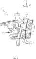
FIGs. 1 to 3 , a vehicle V of the present disclosure comprises abumper assembly 100, thebumper assembly 100 comprising abumper 1 and a reinforcingframe 2. In the specification, a front bumper located at the front of the vehicle is described as an example. However, it should be understood that thebumper 1 may also be a rear bumper of the vehicle V The reinforcingframe 2 is mounted to the bumper through a connectingmember 23. More specifically, the reinforcingframe 2 is arranged adjacent to at least one end T of thebumper 1 in the length direction Y of thebumper 1. Since the vibrations at both ends of thebumper 1 are stronger than those in the middle portion, it is more effective to arrange the reinforcingframe 2 at the end portion T of thebumper 1 than to arrange the reinforcingframe 2 over theentire bumper 1. For example, as shown inFIG. 2 , the reinforcingframe 2 is mounted to the rear of the right end of thefront bumper 1, or to the side facing the interior of the vehicle. It is understood that the reinforcingframe 2 may also be mounted to the left end of thebumper 1 or other desired positions, which is not limitative in the present disclosure. - As shown in
FIGs. 3 to 5 , the reinforcingframe 2 comprises abody 21 and a reinforcingmember 22, wherein the shape of thebody 21 follows the shape of thebumper 1. The reinforcingmember 22 extends from thebody 21 and is oriented towards thebumper 1. At least part of the reinforcingmember 22 provides a supporting force to thebumper 1 to limit a deformation of thebumper 1. - The
body 21 comprises afirst body portion 211 and asecond body portion 212 bent and extending from anedge 2111 of thefirst body portion 211. For example, according to the illustrated embodiment, thefirst body portion 211 is arranged toward the front of the vehicle, and thesecond body portion 212 is arranged toward the lateral side of the vehicle. Thesecond body portion 212 is bent and extends from theedge 2111 of thefirst body portion 211 toward the rear of the vehicle to form an included angle with thefirst body portion 211, and the angle is mated with the bending angle of the end portion of thebumper 1. - The reinforcing
frame 2 comprises at least oneopening 213. For example, thesecond body portion 212 of the reinforcingframe 2 is provided with five groups of substantiallyrectangular openings 213 arranged in the transverse direction (threeopenings 213 for each group), and theseopenings 213 are arranged to substantially cover the entiresecond body portion 212. By providing theseopenings 213, on one hand, it is possible to reduce the overall weight of the reinforcingframe 2 and enhance the operational capability of the vehicle V and on the other hand, other components on the vehicle V can be arranged, and manufacturing costs can be reduced. According to a variant, eachopening 213 may also be shaped as a trapezoid, a circle, an oval, etc. It is understood that the shape, number and position of theopenings 213 may be arranged according to actual needs, which are not limitative in the present disclosure. - As shown in
FIGs. 4 and5 , the reinforcingmember 22 is arranged on thesecond body portion 212. Since other supporting components are arranged in the middle of the bumper, the reinforcingmember 22 is arranged on thesecond body portion 212 located on the side of the end portion of the bumper, which can improve the overall supporting effect for the bumper. The reinforcingmember 22 comprises afirst reinforcement 221 and asecond reinforcement 222. Thefirst reinforcement 221 extends from thebody 21 and is oriented towards thebumper 1. According to the illustrated embodiment, thefirst reinforcement 221 extends from at least part of theperipheral edge 2131 of the at least one opening 213 toward the inside of theopening 213. With this arrangement, a sufficient avoidance space can be arranged for the deformation of thefirst reinforcement 221, so that thefirst reinforcement 221 can provide a greater supporting force to thebumper 1. As an example, thefirst reinforcement 221 extends rightward from the middle of the left edge of theopening 213. According to a variant, thefirst reinforcement 221 extends leftward from the middle of the right edge of theopening 213, or thefirst reinforcement 221 may extend downward from the upper edge of theopening 213, etc. It is understood that the number and position of thefirst reinforcement 221 may be arranged according to actual needs, which are not limitative in the present disclosure. - In some embodiments, the
first reinforcement 221 is configured to have a strip shape extending along the length direction Y of thebumper 1. According to the embodiment shown inFIGs. 6 and 7 , thefirst reinforcement 221 is arranged as an elastic rib having a strip shape extending along the direction Y The elastic rib comprises anextension section 2211 extending from thebody 21, and acompression section 2212 extending obliquely from theextension section 2211 towards thebumper 1. For example, thecompression section 2212 is inclined at an angle of 45 degrees. It is understood that the length of theextension section 2211 and the inclination angle of thecompression section 2212 may be arranged according to actual needs, which are not limitative in the present disclosure. According to a variant, thefirst reinforcement 221 may also be arranged as an elastic sheet. - As shown in
FIG. 5 , thesecond reinforcement 222 is configured as reinforcing ribs protruding from asurface 210 of thebody 21 toward thebumper 1 and staggered along the direction Y and/or the direction Z. According to some embodiments, the reinforcing ribs are arranged around the plurality ofopenings 213 of thefirst body portion 211, and the reinforcing ribs extending substantially along the direction Z intersect with the reinforcing ribs extending substantially along the direction Y According to some embodiments, a longer reinforcing rib extending substantially along the direction Z and a plurality of shorter reinforcing ribs extending substantially along the direction Y are arranged at the connection between thefirst body portion 211 and thesecond body portion 212. Each reinforcing rib extending along the direction Y is connected to the reinforcing rib extending along the direction Z. This embodiment strengthens the structural strength of the connection between thefirst body portion 211 and thesecond body portion 212 and improves the service life of the reinforcingframe 2. It is understood that the number and position of thesecond reinforcement 222 may be arranged according to actual needs, which are not limitative in the present disclosure. - As shown in
FIGs. 3 and4 , thefirst body portion 211 of the reinforcingframe 2 is further provided with apositioning hole 241, and thebumper 1 is provided with apositioning member 242 mated with thepositioning hole 241. The positioningmember 242 protrudes from thebumper 1 and is oriented toward the reinforcingframe 2. The positioningmember 242 passes through thepositioning hole 241 to position the reinforcingframe 2, allowing the mounting of the reinforcingframe 2 to be more convenient and secure. -
FIG. 7 shows three positional relationships of thebumper 1 relative to the reinforcingmember 22 under different stress states. When the vehicle V vibrates, thebumper 1 is subjected to a force F1 along a first direction and a force F2 along a second direction opposite to the first direction, wherein the first direction is a direction away from the reinforcingframe 2, and the second direction is a direction close to the reinforcing frame. When the reinforcingmember 22 is not arranged, thebumper 1 is located at the position P1. After the reinforcingmember 22 is arranged, thefirst reinforcement 221 of the reinforcingmember 22 applies a first supporting force f1 to thebumper 1 along the first direction, and thebumper 1 is deformed from the position P1 to the position P2, i.e., creating a pre-deformation of thebumper 1. At this time, thefirst reinforcement 221 abuts against thebumper 1, and there is a gap D between thesecond reinforcement 222 and thebumper 1. - 1) When the
bumper 1 is subjected to the force F1 along the first direction:
Thebumper 1 is deformed from the position P2 to the position P3 and produces a deformation amount L1. The deformation amount of thebumper 1 decreases as compared with the deformation amount L2 generated when thebumper 1 is deformed from the position P1 to the position P3 without the arrangement of thefirst reinforcement 221; - 2) When the
bumper 1 is subjected to the force F2 along the second direction: - First, the
first reinforcement 221 applies the first supporting force f1 to thebumper 1 along the first direction. As F2 increases, thebumper 1 is deformed from the position P2 to the position P1 when the first supporting force f1 provided by thefirst reinforcement 221 to thebumper 1 is insufficient to resist the F2. Thefirst reinforcement 221 is deformed at this time, and meanwhile thebumper 1 abutting against thesecond reinforcement 222, and thesecond reinforcement 222 additionally provides a second supporting force f2 to thebumper 1. In other words, thefirst reinforcement 221 and thesecond reinforcement 222 support thebumper 1 jointly. - Through the arrangement of the reinforcing
member 22, it is possible to effectively reduce the vibration amplitude of thebumper 1 when thebumper 1 is subjected to external forces due to, such as road bumps, during driving of the vehicle V, to reduce the noise caused by the vibration, and to improve the driving and riding experience for the user. - The connecting
member 23 comprisessnap members 231 arranged substantially along the direction Z, each of thesnap members 231 comprising aclip 2311 and aslot 2312 mated with theclip 2311. Theclip 2311 is arranged on one of the reinforcingframe 2 and thebumper 1, and theslot 2312 is arranged on the other of the reinforcingframe 2 and thebumper 1. For example, according to the embodiment shown inFIGs. 2 and3 , two groups ofsnap members 231 are arranged substantially along the direction Z, theclip 2311 of each group extends from the edge of thebody 21 and is bent toward thebumper 1, and theslot 2312 of each group is arranged at a position of a corresponding side edge of thebumper 1 corresponding to theclip 2311. According to a variant, it is also possible to arrange the clip on the reinforcingframe 2 and the slot at a corresponding position of thebumper 1. It is understood that the number and position of thesnap members 231 may be arranged according to actual needs, which are not limitative in the present disclosure. - As shown in
FIGs. 3 ,4 and8 , the connectingmember 23 further comprises a mountinghole 2321 arranged on thefirst body portion 211, and afastener 2322 mated with the mountinghole 2321. Thefastener 2322 passes through the mountinghole 2321 to mount the reinforcingframe 2 to thebumper 1. For example, thefastener 2322 is arranged as a screw. In addition, the reinforcingframe 2 may also be mounted to thebumper 1 by other means such as welding, which is not limitative in the present disclosure. - The technical contents and features of the present disclosure have been disclosed above. However, it is understood that those skilled in the art can make various changes and improvements to the above-disclosed conception under the creative concept of the present disclosure, and all these various changes and improvements fall within the protection scope of the present disclosure.
- The description of the above embodiments is exemplary rather than limitative, and the protection scope of the present disclosure is defined by the appended claims.
Claims (11)
- A bumper assembly (100), comprisinga bumper (1); anda reinforcing frame (2) mounted to the bumper (1) through a connecting member (23);wherein the reinforcing frame (2) comprises a reinforcing member (22) oriented towards the bumper (1), and at least part of the reinforcing member (22) provides a supporting force to the bumper (1) to limit a deformation of the bumper (1).
- The bumper assembly (100) according to claim 1, wherein the reinforcing frame (2) is arranged adjacent to at least one end (T) of the bumper (1) in a length direction (Y) of the bumper (1).
- The bumper assembly (100) according to claim 2, wherein the reinforcing frame (2) comprises:
a body (21) and the reinforcing member (22) extending from the body (21), wherein the reinforcing member (22) comprises:a first reinforcement (221) abutting against the bumper (1) to provide a first supporting force; anda second reinforcement (222), wherein a gap (D) is arranged between the second reinforcement (222) and the bumper (1);wherein the reinforcing member (22) is configured such that, when the first supporting force provided by the first reinforcement (221) to the bumper (1) is insufficient, the bumper (1) abutting against the second reinforcement (222), and the second reinforcement (222) additionally provides a second supporting force to the bumper (1). - The bumper assembly (100) according to claim 3, wherein the body (21) is shaped to follow the shape of the bumper (1) and comprises:a first body portion (211), anda second body portion (212) bent and extending from an edge (2111) of the first body portion (211);wherein the reinforcing member (22) is arranged on the second body portion (212).
- The bumper assembly (100) according to claim 3, wherein the first reinforcement (221) is configured to have a strip shape extending along the length direction (Y) of the bumper (1).
- The bumper assembly (100) according to claim 3, wherein the first reinforcement (221) comprises:an extension section (2211) extending from the body (21); anda compression section (2212) extending obliquely from the extension portion (2211) towards the bumper (1).
- The bumper assembly (100) according to claim 3, wherein the second reinforcement (222) is configured as a reinforcing rib protruding from a surface (210) of the body (21).
- The bumper assembly (100) according to claim 3, wherein the reinforcing frame (2) further comprises at least one opening (213), and the first reinforcement (221) extends from at least part of a peripheral edge (2131) of the at least one opening (213) toward the inside of the opening (213).
- The bumper assembly (100) according to claim 1, wherein the connecting member (23) comprises:a clip (2311) and a slot (2312) mated with the clip (2311);wherein the clip (2311) is arranged on one of the reinforcing frame (2) and the bumper (1), and the slot (2312) is arranged on the other of the reinforcing frame (2) and the bumper (1).
- The bumper assembly (100) according to claim 4, wherein the connecting member (23) comprises:a mounting hole (2321) arranged on the first body portion (211) of the reinforcing frame (2); anda fastener (2322) passing through the mounting hole (2321) to mount the reinforcing frame (2) to the bumper (1).
- A vehicle (V) comprising the bumper assembly (100) according to any one of claims 1 to 10.
Applications Claiming Priority (1)
| Application Number | Priority Date | Filing Date | Title |
|---|---|---|---|
| CN202310539318.6A CN118928273A (en) | 2023-05-12 | 2023-05-12 | Bumper assembly and vehicle |
Publications (1)
| Publication Number | Publication Date |
|---|---|
| EP4461604A1 true EP4461604A1 (en) | 2024-11-13 |
Family
ID=90717438
Family Applications (1)
| Application Number | Title | Priority Date | Filing Date |
|---|---|---|---|
| EP24168331.7A Withdrawn EP4461604A1 (en) | 2023-05-12 | 2024-04-03 | Bumper assembly and vehicle |
Country Status (2)
| Country | Link |
|---|---|
| EP (1) | EP4461604A1 (en) |
| CN (1) | CN118928273A (en) |
Citations (3)
| Publication number | Priority date | Publication date | Assignee | Title |
|---|---|---|---|---|
| US7540550B1 (en) * | 2008-02-29 | 2009-06-02 | Nissan Technical Center North America, Inc. | Vehicle body structure |
| EP3845421A1 (en) * | 2019-12-30 | 2021-07-07 | Yanfeng Plastic Omnium Automotive Exterior Systems Co., Ltd. | Motor vehicle end structure assembly and assembly method thereof |
| EP4119401A1 (en) * | 2020-03-11 | 2023-01-18 | PSA Automobiles SA | Rear bumper mounting system and vehicle |
-
2023
- 2023-05-12 CN CN202310539318.6A patent/CN118928273A/en active Pending
-
2024
- 2024-04-03 EP EP24168331.7A patent/EP4461604A1/en not_active Withdrawn
Patent Citations (3)
| Publication number | Priority date | Publication date | Assignee | Title |
|---|---|---|---|---|
| US7540550B1 (en) * | 2008-02-29 | 2009-06-02 | Nissan Technical Center North America, Inc. | Vehicle body structure |
| EP3845421A1 (en) * | 2019-12-30 | 2021-07-07 | Yanfeng Plastic Omnium Automotive Exterior Systems Co., Ltd. | Motor vehicle end structure assembly and assembly method thereof |
| EP4119401A1 (en) * | 2020-03-11 | 2023-01-18 | PSA Automobiles SA | Rear bumper mounting system and vehicle |
Also Published As
| Publication number | Publication date |
|---|---|
| CN118928273A (en) | 2024-11-12 |
Similar Documents
| Publication | Publication Date | Title |
|---|---|---|
| US7090289B2 (en) | Vehicle hood | |
| EP2873592B1 (en) | Front spoiler device | |
| EP2514656A1 (en) | Vehicle body floor structure | |
| JP5727883B2 (en) | Bumper structure for vehicles | |
| US11318997B2 (en) | Hood structure | |
| CN106476914A (en) | Reduce resistance elements | |
| WO2008066046A1 (en) | Front structure for cab-over-engine vehicle | |
| CN1273331C (en) | Attaching structure for devices for vehicles | |
| CN101479148B (en) | Cab back panel | |
| WO2009116395A1 (en) | Vehicle bumper structure and energy absorbing body | |
| CN105473423B (en) | The beater or beat-up supporting construction of vehicle | |
| JP2012101697A (en) | Cowl top cover | |
| US10442383B2 (en) | Impact absorber | |
| US7695044B2 (en) | Under-cover support structure | |
| KR101629831B1 (en) | Apparatus for fixing crash pad | |
| JP6863036B2 (en) | Vehicle front structure | |
| CN115431741B (en) | Suspension support structure of vehicle | |
| CN118928273A (en) | Bumper assembly and vehicle | |
| JP5520081B2 (en) | Car cowl structure | |
| KR101272034B1 (en) | Reinforced structure of FEM carrier | |
| JP4450637B2 (en) | Rear underrun protector | |
| JP4423597B2 (en) | Bumper mounting structure | |
| JP3191584B2 (en) | Automotive console box | |
| JP2022139479A (en) | Vehicle front part structure | |
| KR100705052B1 (en) | Fuel Tank Pad |
Legal Events
| Date | Code | Title | Description |
|---|---|---|---|
| PUAI | Public reference made under article 153(3) epc to a published international application that has entered the european phase |
Free format text: ORIGINAL CODE: 0009012 |
|
| STAA | Information on the status of an ep patent application or granted ep patent |
Free format text: STATUS: THE APPLICATION HAS BEEN PUBLISHED |
|
| AK | Designated contracting states |
Kind code of ref document: A1 Designated state(s): AL AT BE BG CH CY CZ DE DK EE ES FI FR GB GR HR HU IE IS IT LI LT LU LV MC ME MK MT NL NO PL PT RO RS SE SI SK SM TR |
|
| STAA | Information on the status of an ep patent application or granted ep patent |
Free format text: STATUS: THE APPLICATION IS DEEMED TO BE WITHDRAWN |
|
| 18D | Application deemed to be withdrawn |
Effective date: 20250514 |