EP4461580A1 - Battery management apparatus and operation method therefor - Google Patents
Battery management apparatus and operation method therefor Download PDFInfo
- Publication number
- EP4461580A1 EP4461580A1 EP22927465.9A EP22927465A EP4461580A1 EP 4461580 A1 EP4461580 A1 EP 4461580A1 EP 22927465 A EP22927465 A EP 22927465A EP 4461580 A1 EP4461580 A1 EP 4461580A1
- Authority
- EP
- European Patent Office
- Prior art keywords
- fire
- battery
- charger
- charge
- monitoring
- Prior art date
- Legal status (The legal status is an assumption and is not a legal conclusion. Google has not performed a legal analysis and makes no representation as to the accuracy of the status listed.)
- Pending
Links
Images





Classifications
-
- B—PERFORMING OPERATIONS; TRANSPORTING
- B60—VEHICLES IN GENERAL
- B60L—PROPULSION OF ELECTRICALLY-PROPELLED VEHICLES; SUPPLYING ELECTRIC POWER FOR AUXILIARY EQUIPMENT OF ELECTRICALLY-PROPELLED VEHICLES; ELECTRODYNAMIC BRAKE SYSTEMS FOR VEHICLES IN GENERAL; MAGNETIC SUSPENSION OR LEVITATION FOR VEHICLES; MONITORING OPERATING VARIABLES OF ELECTRICALLY-PROPELLED VEHICLES; ELECTRIC SAFETY DEVICES FOR ELECTRICALLY-PROPELLED VEHICLES
- B60L58/00—Methods or circuit arrangements for monitoring or controlling batteries or fuel cells, specially adapted for electric vehicles
- B60L58/10—Methods or circuit arrangements for monitoring or controlling batteries or fuel cells, specially adapted for electric vehicles for monitoring or controlling batteries
- B60L58/12—Methods or circuit arrangements for monitoring or controlling batteries or fuel cells, specially adapted for electric vehicles for monitoring or controlling batteries responding to state of charge [SoC]
-
- B—PERFORMING OPERATIONS; TRANSPORTING
- B60—VEHICLES IN GENERAL
- B60L—PROPULSION OF ELECTRICALLY-PROPELLED VEHICLES; SUPPLYING ELECTRIC POWER FOR AUXILIARY EQUIPMENT OF ELECTRICALLY-PROPELLED VEHICLES; ELECTRODYNAMIC BRAKE SYSTEMS FOR VEHICLES IN GENERAL; MAGNETIC SUSPENSION OR LEVITATION FOR VEHICLES; MONITORING OPERATING VARIABLES OF ELECTRICALLY-PROPELLED VEHICLES; ELECTRIC SAFETY DEVICES FOR ELECTRICALLY-PROPELLED VEHICLES
- B60L53/00—Methods of charging batteries, specially adapted for electric vehicles; Charging stations or on-board charging equipment therefor; Exchange of energy storage elements in electric vehicles
- B60L53/60—Monitoring or controlling charging stations
- B60L53/62—Monitoring or controlling charging stations in response to charging parameters, e.g. current, voltage or electrical charge
-
- A—HUMAN NECESSITIES
- A62—LIFE-SAVING; FIRE-FIGHTING
- A62C—FIRE-FIGHTING
- A62C37/00—Control of fire-fighting equipment
- A62C37/36—Control of fire-fighting equipment an actuating signal being generated by a sensor separate from an outlet device
- A62C37/38—Control of fire-fighting equipment an actuating signal being generated by a sensor separate from an outlet device by both sensor and actuator, e.g. valve, being in the danger zone
- A62C37/40—Control of fire-fighting equipment an actuating signal being generated by a sensor separate from an outlet device by both sensor and actuator, e.g. valve, being in the danger zone with electric connection between sensor and actuator
-
- B—PERFORMING OPERATIONS; TRANSPORTING
- B60—VEHICLES IN GENERAL
- B60L—PROPULSION OF ELECTRICALLY-PROPELLED VEHICLES; SUPPLYING ELECTRIC POWER FOR AUXILIARY EQUIPMENT OF ELECTRICALLY-PROPELLED VEHICLES; ELECTRODYNAMIC BRAKE SYSTEMS FOR VEHICLES IN GENERAL; MAGNETIC SUSPENSION OR LEVITATION FOR VEHICLES; MONITORING OPERATING VARIABLES OF ELECTRICALLY-PROPELLED VEHICLES; ELECTRIC SAFETY DEVICES FOR ELECTRICALLY-PROPELLED VEHICLES
- B60L3/00—Electric devices on electrically-propelled vehicles for safety purposes; Monitoring operating variables, e.g. speed, deceleration or energy consumption
-
- B—PERFORMING OPERATIONS; TRANSPORTING
- B60—VEHICLES IN GENERAL
- B60L—PROPULSION OF ELECTRICALLY-PROPELLED VEHICLES; SUPPLYING ELECTRIC POWER FOR AUXILIARY EQUIPMENT OF ELECTRICALLY-PROPELLED VEHICLES; ELECTRODYNAMIC BRAKE SYSTEMS FOR VEHICLES IN GENERAL; MAGNETIC SUSPENSION OR LEVITATION FOR VEHICLES; MONITORING OPERATING VARIABLES OF ELECTRICALLY-PROPELLED VEHICLES; ELECTRIC SAFETY DEVICES FOR ELECTRICALLY-PROPELLED VEHICLES
- B60L3/00—Electric devices on electrically-propelled vehicles for safety purposes; Monitoring operating variables, e.g. speed, deceleration or energy consumption
- B60L3/0023—Detecting, eliminating, remedying or compensating for drive train abnormalities, e.g. failures within the drive train
- B60L3/003—Detecting, eliminating, remedying or compensating for drive train abnormalities, e.g. failures within the drive train relating to inverters
-
- B—PERFORMING OPERATIONS; TRANSPORTING
- B60—VEHICLES IN GENERAL
- B60L—PROPULSION OF ELECTRICALLY-PROPELLED VEHICLES; SUPPLYING ELECTRIC POWER FOR AUXILIARY EQUIPMENT OF ELECTRICALLY-PROPELLED VEHICLES; ELECTRODYNAMIC BRAKE SYSTEMS FOR VEHICLES IN GENERAL; MAGNETIC SUSPENSION OR LEVITATION FOR VEHICLES; MONITORING OPERATING VARIABLES OF ELECTRICALLY-PROPELLED VEHICLES; ELECTRIC SAFETY DEVICES FOR ELECTRICALLY-PROPELLED VEHICLES
- B60L3/00—Electric devices on electrically-propelled vehicles for safety purposes; Monitoring operating variables, e.g. speed, deceleration or energy consumption
- B60L3/0023—Detecting, eliminating, remedying or compensating for drive train abnormalities, e.g. failures within the drive train
- B60L3/0046—Detecting, eliminating, remedying or compensating for drive train abnormalities, e.g. failures within the drive train relating to electric energy storage systems, e.g. batteries or capacitors
-
- B—PERFORMING OPERATIONS; TRANSPORTING
- B60—VEHICLES IN GENERAL
- B60L—PROPULSION OF ELECTRICALLY-PROPELLED VEHICLES; SUPPLYING ELECTRIC POWER FOR AUXILIARY EQUIPMENT OF ELECTRICALLY-PROPELLED VEHICLES; ELECTRODYNAMIC BRAKE SYSTEMS FOR VEHICLES IN GENERAL; MAGNETIC SUSPENSION OR LEVITATION FOR VEHICLES; MONITORING OPERATING VARIABLES OF ELECTRICALLY-PROPELLED VEHICLES; ELECTRIC SAFETY DEVICES FOR ELECTRICALLY-PROPELLED VEHICLES
- B60L3/00—Electric devices on electrically-propelled vehicles for safety purposes; Monitoring operating variables, e.g. speed, deceleration or energy consumption
- B60L3/0023—Detecting, eliminating, remedying or compensating for drive train abnormalities, e.g. failures within the drive train
- B60L3/0069—Detecting, eliminating, remedying or compensating for drive train abnormalities, e.g. failures within the drive train relating to the isolation, e.g. ground fault or leak current
-
- B—PERFORMING OPERATIONS; TRANSPORTING
- B60—VEHICLES IN GENERAL
- B60L—PROPULSION OF ELECTRICALLY-PROPELLED VEHICLES; SUPPLYING ELECTRIC POWER FOR AUXILIARY EQUIPMENT OF ELECTRICALLY-PROPELLED VEHICLES; ELECTRODYNAMIC BRAKE SYSTEMS FOR VEHICLES IN GENERAL; MAGNETIC SUSPENSION OR LEVITATION FOR VEHICLES; MONITORING OPERATING VARIABLES OF ELECTRICALLY-PROPELLED VEHICLES; ELECTRIC SAFETY DEVICES FOR ELECTRICALLY-PROPELLED VEHICLES
- B60L3/00—Electric devices on electrically-propelled vehicles for safety purposes; Monitoring operating variables, e.g. speed, deceleration or energy consumption
- B60L3/0092—Electric devices on electrically-propelled vehicles for safety purposes; Monitoring operating variables, e.g. speed, deceleration or energy consumption with use of redundant elements for safety purposes
-
- B—PERFORMING OPERATIONS; TRANSPORTING
- B60—VEHICLES IN GENERAL
- B60L—PROPULSION OF ELECTRICALLY-PROPELLED VEHICLES; SUPPLYING ELECTRIC POWER FOR AUXILIARY EQUIPMENT OF ELECTRICALLY-PROPELLED VEHICLES; ELECTRODYNAMIC BRAKE SYSTEMS FOR VEHICLES IN GENERAL; MAGNETIC SUSPENSION OR LEVITATION FOR VEHICLES; MONITORING OPERATING VARIABLES OF ELECTRICALLY-PROPELLED VEHICLES; ELECTRIC SAFETY DEVICES FOR ELECTRICALLY-PROPELLED VEHICLES
- B60L3/00—Electric devices on electrically-propelled vehicles for safety purposes; Monitoring operating variables, e.g. speed, deceleration or energy consumption
- B60L3/04—Cutting off the power supply under fault conditions
-
- B—PERFORMING OPERATIONS; TRANSPORTING
- B60—VEHICLES IN GENERAL
- B60L—PROPULSION OF ELECTRICALLY-PROPELLED VEHICLES; SUPPLYING ELECTRIC POWER FOR AUXILIARY EQUIPMENT OF ELECTRICALLY-PROPELLED VEHICLES; ELECTRODYNAMIC BRAKE SYSTEMS FOR VEHICLES IN GENERAL; MAGNETIC SUSPENSION OR LEVITATION FOR VEHICLES; MONITORING OPERATING VARIABLES OF ELECTRICALLY-PROPELLED VEHICLES; ELECTRIC SAFETY DEVICES FOR ELECTRICALLY-PROPELLED VEHICLES
- B60L3/00—Electric devices on electrically-propelled vehicles for safety purposes; Monitoring operating variables, e.g. speed, deceleration or energy consumption
- B60L3/12—Recording operating variables ; Monitoring of operating variables
-
- B—PERFORMING OPERATIONS; TRANSPORTING
- B60—VEHICLES IN GENERAL
- B60L—PROPULSION OF ELECTRICALLY-PROPELLED VEHICLES; SUPPLYING ELECTRIC POWER FOR AUXILIARY EQUIPMENT OF ELECTRICALLY-PROPELLED VEHICLES; ELECTRODYNAMIC BRAKE SYSTEMS FOR VEHICLES IN GENERAL; MAGNETIC SUSPENSION OR LEVITATION FOR VEHICLES; MONITORING OPERATING VARIABLES OF ELECTRICALLY-PROPELLED VEHICLES; ELECTRIC SAFETY DEVICES FOR ELECTRICALLY-PROPELLED VEHICLES
- B60L53/00—Methods of charging batteries, specially adapted for electric vehicles; Charging stations or on-board charging equipment therefor; Exchange of energy storage elements in electric vehicles
- B60L53/10—Methods of charging batteries, specially adapted for electric vehicles; Charging stations or on-board charging equipment therefor; Exchange of energy storage elements in electric vehicles characterised by the energy transfer between the charging station and the vehicle
- B60L53/14—Conductive energy transfer
- B60L53/18—Cables specially adapted for charging electric vehicles
-
- B—PERFORMING OPERATIONS; TRANSPORTING
- B60—VEHICLES IN GENERAL
- B60L—PROPULSION OF ELECTRICALLY-PROPELLED VEHICLES; SUPPLYING ELECTRIC POWER FOR AUXILIARY EQUIPMENT OF ELECTRICALLY-PROPELLED VEHICLES; ELECTRODYNAMIC BRAKE SYSTEMS FOR VEHICLES IN GENERAL; MAGNETIC SUSPENSION OR LEVITATION FOR VEHICLES; MONITORING OPERATING VARIABLES OF ELECTRICALLY-PROPELLED VEHICLES; ELECTRIC SAFETY DEVICES FOR ELECTRICALLY-PROPELLED VEHICLES
- B60L53/00—Methods of charging batteries, specially adapted for electric vehicles; Charging stations or on-board charging equipment therefor; Exchange of energy storage elements in electric vehicles
- B60L53/60—Monitoring or controlling charging stations
-
- B—PERFORMING OPERATIONS; TRANSPORTING
- B60—VEHICLES IN GENERAL
- B60L—PROPULSION OF ELECTRICALLY-PROPELLED VEHICLES; SUPPLYING ELECTRIC POWER FOR AUXILIARY EQUIPMENT OF ELECTRICALLY-PROPELLED VEHICLES; ELECTRODYNAMIC BRAKE SYSTEMS FOR VEHICLES IN GENERAL; MAGNETIC SUSPENSION OR LEVITATION FOR VEHICLES; MONITORING OPERATING VARIABLES OF ELECTRICALLY-PROPELLED VEHICLES; ELECTRIC SAFETY DEVICES FOR ELECTRICALLY-PROPELLED VEHICLES
- B60L53/00—Methods of charging batteries, specially adapted for electric vehicles; Charging stations or on-board charging equipment therefor; Exchange of energy storage elements in electric vehicles
- B60L53/60—Monitoring or controlling charging stations
- B60L53/68—Off-site monitoring or control, e.g. remote control
-
- B—PERFORMING OPERATIONS; TRANSPORTING
- B60—VEHICLES IN GENERAL
- B60L—PROPULSION OF ELECTRICALLY-PROPELLED VEHICLES; SUPPLYING ELECTRIC POWER FOR AUXILIARY EQUIPMENT OF ELECTRICALLY-PROPELLED VEHICLES; ELECTRODYNAMIC BRAKE SYSTEMS FOR VEHICLES IN GENERAL; MAGNETIC SUSPENSION OR LEVITATION FOR VEHICLES; MONITORING OPERATING VARIABLES OF ELECTRICALLY-PROPELLED VEHICLES; ELECTRIC SAFETY DEVICES FOR ELECTRICALLY-PROPELLED VEHICLES
- B60L58/00—Methods or circuit arrangements for monitoring or controlling batteries or fuel cells, specially adapted for electric vehicles
- B60L58/10—Methods or circuit arrangements for monitoring or controlling batteries or fuel cells, specially adapted for electric vehicles for monitoring or controlling batteries
-
- B—PERFORMING OPERATIONS; TRANSPORTING
- B60—VEHICLES IN GENERAL
- B60L—PROPULSION OF ELECTRICALLY-PROPELLED VEHICLES; SUPPLYING ELECTRIC POWER FOR AUXILIARY EQUIPMENT OF ELECTRICALLY-PROPELLED VEHICLES; ELECTRODYNAMIC BRAKE SYSTEMS FOR VEHICLES IN GENERAL; MAGNETIC SUSPENSION OR LEVITATION FOR VEHICLES; MONITORING OPERATING VARIABLES OF ELECTRICALLY-PROPELLED VEHICLES; ELECTRIC SAFETY DEVICES FOR ELECTRICALLY-PROPELLED VEHICLES
- B60L58/00—Methods or circuit arrangements for monitoring or controlling batteries or fuel cells, specially adapted for electric vehicles
- B60L58/10—Methods or circuit arrangements for monitoring or controlling batteries or fuel cells, specially adapted for electric vehicles for monitoring or controlling batteries
- B60L58/12—Methods or circuit arrangements for monitoring or controlling batteries or fuel cells, specially adapted for electric vehicles for monitoring or controlling batteries responding to state of charge [SoC]
- B60L58/15—Preventing overcharging
-
- B—PERFORMING OPERATIONS; TRANSPORTING
- B60—VEHICLES IN GENERAL
- B60L—PROPULSION OF ELECTRICALLY-PROPELLED VEHICLES; SUPPLYING ELECTRIC POWER FOR AUXILIARY EQUIPMENT OF ELECTRICALLY-PROPELLED VEHICLES; ELECTRODYNAMIC BRAKE SYSTEMS FOR VEHICLES IN GENERAL; MAGNETIC SUSPENSION OR LEVITATION FOR VEHICLES; MONITORING OPERATING VARIABLES OF ELECTRICALLY-PROPELLED VEHICLES; ELECTRIC SAFETY DEVICES FOR ELECTRICALLY-PROPELLED VEHICLES
- B60L58/00—Methods or circuit arrangements for monitoring or controlling batteries or fuel cells, specially adapted for electric vehicles
- B60L58/10—Methods or circuit arrangements for monitoring or controlling batteries or fuel cells, specially adapted for electric vehicles for monitoring or controlling batteries
- B60L58/24—Methods or circuit arrangements for monitoring or controlling batteries or fuel cells, specially adapted for electric vehicles for monitoring or controlling batteries for controlling the temperature of batteries
-
- H—ELECTRICITY
- H01—ELECTRIC ELEMENTS
- H01M—PROCESSES OR MEANS, e.g. BATTERIES, FOR THE DIRECT CONVERSION OF CHEMICAL ENERGY INTO ELECTRICAL ENERGY
- H01M10/00—Secondary cells; Manufacture thereof
- H01M10/42—Methods or arrangements for servicing or maintenance of secondary cells or secondary half-cells
- H01M10/425—Structural combination with electronic components, e.g. electronic circuits integrated to the outside of the casing
-
- H—ELECTRICITY
- H01—ELECTRIC ELEMENTS
- H01M—PROCESSES OR MEANS, e.g. BATTERIES, FOR THE DIRECT CONVERSION OF CHEMICAL ENERGY INTO ELECTRICAL ENERGY
- H01M10/00—Secondary cells; Manufacture thereof
- H01M10/42—Methods or arrangements for servicing or maintenance of secondary cells or secondary half-cells
- H01M10/44—Methods for charging or discharging
-
- H—ELECTRICITY
- H01—ELECTRIC ELEMENTS
- H01M—PROCESSES OR MEANS, e.g. BATTERIES, FOR THE DIRECT CONVERSION OF CHEMICAL ENERGY INTO ELECTRICAL ENERGY
- H01M50/00—Constructional details or processes of manufacture of the non-active parts of electrochemical cells other than fuel cells, e.g. hybrid cells
- H01M50/30—Arrangements for facilitating escape of gases
- H01M50/383—Flame arresting or ignition-preventing means
-
- H—ELECTRICITY
- H02—GENERATION; CONVERSION OR DISTRIBUTION OF ELECTRIC POWER
- H02J—ELECTRIC POWER NETWORKS; CIRCUIT ARRANGEMENTS OR SYSTEMS FOR SUPPLYING OR DISTRIBUTING ELECTRIC POWER; SYSTEMS FOR STORING ELECTRIC ENERGY
- H02J7/00—Circuit arrangements for charging or discharging batteries or for supplying loads from batteries
- H02J7/90—Regulation of charging or discharging current or voltage
- H02J7/933—Regulation of charging or discharging current or voltage the cycle being controlled or terminated in response to electric parameters
-
- A—HUMAN NECESSITIES
- A62—LIFE-SAVING; FIRE-FIGHTING
- A62C—FIRE-FIGHTING
- A62C3/00—Fire prevention, containment or extinguishing specially adapted for particular objects or places
- A62C3/07—Fire prevention, containment or extinguishing specially adapted for particular objects or places in vehicles, e.g. in road vehicles
-
- A—HUMAN NECESSITIES
- A62—LIFE-SAVING; FIRE-FIGHTING
- A62C—FIRE-FIGHTING
- A62C3/00—Fire prevention, containment or extinguishing specially adapted for particular objects or places
- A62C3/16—Fire prevention, containment or extinguishing specially adapted for particular objects or places in electrical installations, e.g. cableways
-
- A—HUMAN NECESSITIES
- A62—LIFE-SAVING; FIRE-FIGHTING
- A62C—FIRE-FIGHTING
- A62C37/00—Control of fire-fighting equipment
- A62C37/36—Control of fire-fighting equipment an actuating signal being generated by a sensor separate from an outlet device
- A62C37/44—Control of fire-fighting equipment an actuating signal being generated by a sensor separate from an outlet device only the sensor being in the danger zone
-
- B—PERFORMING OPERATIONS; TRANSPORTING
- B60—VEHICLES IN GENERAL
- B60L—PROPULSION OF ELECTRICALLY-PROPELLED VEHICLES; SUPPLYING ELECTRIC POWER FOR AUXILIARY EQUIPMENT OF ELECTRICALLY-PROPELLED VEHICLES; ELECTRODYNAMIC BRAKE SYSTEMS FOR VEHICLES IN GENERAL; MAGNETIC SUSPENSION OR LEVITATION FOR VEHICLES; MONITORING OPERATING VARIABLES OF ELECTRICALLY-PROPELLED VEHICLES; ELECTRIC SAFETY DEVICES FOR ELECTRICALLY-PROPELLED VEHICLES
- B60L2240/00—Control parameters of input or output; Target parameters
- B60L2240/40—Drive Train control parameters
- B60L2240/54—Drive Train control parameters related to batteries
- B60L2240/545—Temperature
-
- B—PERFORMING OPERATIONS; TRANSPORTING
- B60—VEHICLES IN GENERAL
- B60L—PROPULSION OF ELECTRICALLY-PROPELLED VEHICLES; SUPPLYING ELECTRIC POWER FOR AUXILIARY EQUIPMENT OF ELECTRICALLY-PROPELLED VEHICLES; ELECTRODYNAMIC BRAKE SYSTEMS FOR VEHICLES IN GENERAL; MAGNETIC SUSPENSION OR LEVITATION FOR VEHICLES; MONITORING OPERATING VARIABLES OF ELECTRICALLY-PROPELLED VEHICLES; ELECTRIC SAFETY DEVICES FOR ELECTRICALLY-PROPELLED VEHICLES
- B60L2240/00—Control parameters of input or output; Target parameters
- B60L2240/40—Drive Train control parameters
- B60L2240/54—Drive Train control parameters related to batteries
- B60L2240/547—Voltage
-
- B—PERFORMING OPERATIONS; TRANSPORTING
- B60—VEHICLES IN GENERAL
- B60L—PROPULSION OF ELECTRICALLY-PROPELLED VEHICLES; SUPPLYING ELECTRIC POWER FOR AUXILIARY EQUIPMENT OF ELECTRICALLY-PROPELLED VEHICLES; ELECTRODYNAMIC BRAKE SYSTEMS FOR VEHICLES IN GENERAL; MAGNETIC SUSPENSION OR LEVITATION FOR VEHICLES; MONITORING OPERATING VARIABLES OF ELECTRICALLY-PROPELLED VEHICLES; ELECTRIC SAFETY DEVICES FOR ELECTRICALLY-PROPELLED VEHICLES
- B60L2240/00—Control parameters of input or output; Target parameters
- B60L2240/40—Drive Train control parameters
- B60L2240/54—Drive Train control parameters related to batteries
- B60L2240/549—Current
-
- B—PERFORMING OPERATIONS; TRANSPORTING
- B60—VEHICLES IN GENERAL
- B60L—PROPULSION OF ELECTRICALLY-PROPELLED VEHICLES; SUPPLYING ELECTRIC POWER FOR AUXILIARY EQUIPMENT OF ELECTRICALLY-PROPELLED VEHICLES; ELECTRODYNAMIC BRAKE SYSTEMS FOR VEHICLES IN GENERAL; MAGNETIC SUSPENSION OR LEVITATION FOR VEHICLES; MONITORING OPERATING VARIABLES OF ELECTRICALLY-PROPELLED VEHICLES; ELECTRIC SAFETY DEVICES FOR ELECTRICALLY-PROPELLED VEHICLES
- B60L2250/00—Driver interactions
- B60L2250/10—Driver interactions by alarm
-
- B—PERFORMING OPERATIONS; TRANSPORTING
- B60—VEHICLES IN GENERAL
- B60L—PROPULSION OF ELECTRICALLY-PROPELLED VEHICLES; SUPPLYING ELECTRIC POWER FOR AUXILIARY EQUIPMENT OF ELECTRICALLY-PROPELLED VEHICLES; ELECTRODYNAMIC BRAKE SYSTEMS FOR VEHICLES IN GENERAL; MAGNETIC SUSPENSION OR LEVITATION FOR VEHICLES; MONITORING OPERATING VARIABLES OF ELECTRICALLY-PROPELLED VEHICLES; ELECTRIC SAFETY DEVICES FOR ELECTRICALLY-PROPELLED VEHICLES
- B60L2250/00—Driver interactions
- B60L2250/12—Driver interactions by confirmation, e.g. of the input
-
- B—PERFORMING OPERATIONS; TRANSPORTING
- B60—VEHICLES IN GENERAL
- B60L—PROPULSION OF ELECTRICALLY-PROPELLED VEHICLES; SUPPLYING ELECTRIC POWER FOR AUXILIARY EQUIPMENT OF ELECTRICALLY-PROPELLED VEHICLES; ELECTRODYNAMIC BRAKE SYSTEMS FOR VEHICLES IN GENERAL; MAGNETIC SUSPENSION OR LEVITATION FOR VEHICLES; MONITORING OPERATING VARIABLES OF ELECTRICALLY-PROPELLED VEHICLES; ELECTRIC SAFETY DEVICES FOR ELECTRICALLY-PROPELLED VEHICLES
- B60L2250/00—Driver interactions
- B60L2250/16—Driver interactions by display
-
- B—PERFORMING OPERATIONS; TRANSPORTING
- B60—VEHICLES IN GENERAL
- B60Y—INDEXING SCHEME RELATING TO ASPECTS CROSS-CUTTING VEHICLE TECHNOLOGY
- B60Y2200/00—Type of vehicle
- B60Y2200/90—Vehicles comprising electric prime movers
- B60Y2200/91—Electric vehicles
-
- H—ELECTRICITY
- H01—ELECTRIC ELEMENTS
- H01M—PROCESSES OR MEANS, e.g. BATTERIES, FOR THE DIRECT CONVERSION OF CHEMICAL ENERGY INTO ELECTRICAL ENERGY
- H01M10/00—Secondary cells; Manufacture thereof
- H01M10/42—Methods or arrangements for servicing or maintenance of secondary cells or secondary half-cells
- H01M10/425—Structural combination with electronic components, e.g. electronic circuits integrated to the outside of the casing
- H01M2010/4271—Battery management systems including electronic circuits, e.g. control of current or voltage to keep battery in healthy state, cell balancing
-
- H—ELECTRICITY
- H01—ELECTRIC ELEMENTS
- H01M—PROCESSES OR MEANS, e.g. BATTERIES, FOR THE DIRECT CONVERSION OF CHEMICAL ENERGY INTO ELECTRICAL ENERGY
- H01M10/00—Secondary cells; Manufacture thereof
- H01M10/42—Methods or arrangements for servicing or maintenance of secondary cells or secondary half-cells
- H01M10/425—Structural combination with electronic components, e.g. electronic circuits integrated to the outside of the casing
- H01M2010/4278—Systems for data transfer from batteries, e.g. transfer of battery parameters to a controller, data transferred between battery controller and main controller
-
- H—ELECTRICITY
- H01—ELECTRIC ELEMENTS
- H01M—PROCESSES OR MEANS, e.g. BATTERIES, FOR THE DIRECT CONVERSION OF CHEMICAL ENERGY INTO ELECTRICAL ENERGY
- H01M2220/00—Batteries for particular applications
- H01M2220/20—Batteries in motive systems, e.g. vehicle, ship, plane
-
- Y—GENERAL TAGGING OF NEW TECHNOLOGICAL DEVELOPMENTS; GENERAL TAGGING OF CROSS-SECTIONAL TECHNOLOGIES SPANNING OVER SEVERAL SECTIONS OF THE IPC; TECHNICAL SUBJECTS COVERED BY FORMER USPC CROSS-REFERENCE ART COLLECTIONS [XRACs] AND DIGESTS
- Y02—TECHNOLOGIES OR APPLICATIONS FOR MITIGATION OR ADAPTATION AGAINST CLIMATE CHANGE
- Y02T—CLIMATE CHANGE MITIGATION TECHNOLOGIES RELATED TO TRANSPORTATION
- Y02T10/00—Road transport of goods or passengers
- Y02T10/60—Other road transportation technologies with climate change mitigation effect
- Y02T10/70—Energy storage systems for electromobility, e.g. batteries
-
- Y—GENERAL TAGGING OF NEW TECHNOLOGICAL DEVELOPMENTS; GENERAL TAGGING OF CROSS-SECTIONAL TECHNOLOGIES SPANNING OVER SEVERAL SECTIONS OF THE IPC; TECHNICAL SUBJECTS COVERED BY FORMER USPC CROSS-REFERENCE ART COLLECTIONS [XRACs] AND DIGESTS
- Y02—TECHNOLOGIES OR APPLICATIONS FOR MITIGATION OR ADAPTATION AGAINST CLIMATE CHANGE
- Y02T—CLIMATE CHANGE MITIGATION TECHNOLOGIES RELATED TO TRANSPORTATION
- Y02T10/00—Road transport of goods or passengers
- Y02T10/60—Other road transportation technologies with climate change mitigation effect
- Y02T10/7072—Electromobility specific charging systems or methods for batteries, ultracapacitors, supercapacitors or double-layer capacitors
-
- Y—GENERAL TAGGING OF NEW TECHNOLOGICAL DEVELOPMENTS; GENERAL TAGGING OF CROSS-SECTIONAL TECHNOLOGIES SPANNING OVER SEVERAL SECTIONS OF THE IPC; TECHNICAL SUBJECTS COVERED BY FORMER USPC CROSS-REFERENCE ART COLLECTIONS [XRACs] AND DIGESTS
- Y02—TECHNOLOGIES OR APPLICATIONS FOR MITIGATION OR ADAPTATION AGAINST CLIMATE CHANGE
- Y02T—CLIMATE CHANGE MITIGATION TECHNOLOGIES RELATED TO TRANSPORTATION
- Y02T10/00—Road transport of goods or passengers
- Y02T10/60—Other road transportation technologies with climate change mitigation effect
- Y02T10/72—Electric energy management in electromobility
Definitions
- Embodiments disclosed herein relate to a battery management apparatus and an operating method thereof.
- the secondary batteries which are chargeable/dischargeable batteries, may include all of conventional nickel (Ni)/cadmium (Cd) batteries, Ni/metal hydride (MH) batteries, etc., and recent lithium-ion batteries.
- a lithium-ion battery has a much higher energy density than those of the conventional Ni/Cd batteries, Ni/MH batteries, etc.
- the lithium-ion battery may be manufactured to be small and lightweight, such that the lithium-ion battery has been used as a power source of mobile devices, and recently, a use range thereof has been extended to power sources for electric vehicles, attracting attention as next-generation energy storage media.
- Embodiments disclosed herein aim to provide a battery management apparatus and an operating method thereof in which in case of occurrence of ignition inside a vehicle after completion of vehicle charge, an operation of detecting and preventing ignition may be performed.
- Embodiments disclosed herein aim to provide a battery management apparatus and an operating method thereof in which after completion of vehicle charge, minimum power may be supplied from a charging connector to enable constant monitoring of ignition inside the vehicle.
- a battery management apparatus includes a sensor configured to generate information about occurrence of fire and a controller configured to control charge of the battery based on power for charging the battery, supplied from a charger, monitor the information about occurrence of the fire based on power for monitoring the fire, supplied from the charger, upon completion of charge of the battery, and determine whether the fire occurs based on a monitoring result.
- the controller may be further configured to control another device inside the vehicle to perform an operation for preventing the fire, based on whether the fire occurs.
- the controller may be further configured to store information about the fire in the charger or the battery management apparatus when determining that the fire occurs.
- the controller may be further configured to receive minimum power for determining whether the fire occurs from the charger.
- the controller may be further configured to determine whether connection with the charger is released, upon completion of the charge of the battery, request supply of power for monitoring the fire to the charger when determining that connection with the charger is not released, and receive the power for monitoring the fire from the charger.
- the controller may be further configured to switch to a sleep mode when determining that connection with the charger is released.
- the controller may be further configured to receive a user command for activating or deactivating a fire monitoring function, upon completion of the charge of the battery during activation of the fire monitoring function in response to a first user command, monitor the information about occurrence of the fire based on the power for monitoring the fire after completion of the charge, and upon completion of the charge of the battery during deactivation of the fire monitoring function in response to a second user command, switch to a sleep mode after completion of the charge.
- An operating method of a battery management apparatus includes generating information about occurrence of fire, controlling charge of the battery based on power for charging the battery, supplied from a charger, monitoring the information about occurrence of the fire, based on power for monitoring the fire, supplied from the charger, upon completion of the charge of the battery, and determining whether the fire occurs, based on a monitoring result.
- the operating method may further include controlling another device inside the vehicle to perform an operation for preventing the fire, based on whether the fire occurs.
- the operating method may further include storing information about the fire in the charger or the battery management apparatus when determining that the fire occurs.
- the operating method may further include determining whether connection with the charger is released, upon completion of the charge of the battery and requesting supply of power for monitoring the fire to the charger when determining that connection with the charger is not released, and receiving power for monitoring the fire from the charger or switching to a sleep mode when determining that connection with the charger is released.
- the operating method may further include receiving a user command for activating or deactivating a fire monitoring function and upon completion of the charge of the battery during activation of the fire monitoring function in response to a first user command, monitoring the information about occurrence of the fire based on the power for monitoring the fire after completion of the charge or upon completion of the charge of the battery during deactivation of the fire monitoring function in response to a second user command, switching to a sleep mode after completion of the charge.
- a battery management apparatus and an operating method thereof may detect ignition inside a vehicle and perform a required operation because there is no need to enter a sleep mode even when charge of the vehicle is completed.
- a battery management apparatus and an operating method thereof may constantly monitor a state of the vehicle after completion of charge of the vehicle to collect data in case of occurrence of ignition inside the vehicle, thereby fundamentally analyzing a cause for the ignition.
- a battery management apparatus and an operating method thereof may receive minimum power from the charger after completion of the charge of the vehicle to maintain an operation mode without entering the sleep mode, thereby detecting in advance a cause for ignition inside the vehicle and taking measures to the ignition.
- a battery management apparatus and an operating method thereof may provide, to the user, a user interface for selecting whether to enter the sleep mode or maintain the operation mode to the user after completion of the charge of the vehicle, thereby allowing the user to make selection.
- terms such as first, second, A, B, (a), (b), etc. may be used. These terms are used merely for distinguishing one component from another component and do not limit the component to the essence, sequence, order, etc., of the component.
- the terms used herein, including technical and scientific terms, have the same meanings as terms that are generally understood by those skilled in the art, as long as the terms are not differently defined.
- the terms defined in a generally used dictionary should be interpreted as having the same meanings as the contextual meanings of the relevant technology and should not be interpreted as having ideal or exaggerated meanings unless they are clearly defined in the present application.
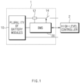
- FIG. 1 is a block diagram of a general battery pack.
- FIG. 1 a battery control system including a battery pack 1 and a higher-level controller 2 included in a higher-level system according to an embodiment of the present disclosure is schematically shown.
- the battery pack 1 may include a battery module 10 that includes one or more battery cells and is chargeable/dischargeable, a switching unit 14 serially connected to a positive (+) terminal side or a negative (-) terminal side of the battery module 10 to control a charging/discharging current flow of the battery module 10, and a battery management system 20 for control and management to prevent overcharging and over-discharging by monitoring voltage, current, temperature, etc., of the battery pack 1.
- the battery pack 1 may include the battery module 10, the sensor 12, the switching unit 14, and the battery management system 20 provided in plural.
- the switching unit 14 which is an element for controlling a current flow for charging or discharging of the plurality of battery modules 10, for example, at least one relay, magnetic contactor, etc., may be used according to specifications of the battery pack 1.
- the battery management system 20 which is an interface for receiving measurement values of the above-described various parameter values, may include a plurality of terminals and a circuit, etc., connected thereto to process input values.
- the battery management system 20 may control on/off of the switching unit 14, e.g., a relay, a contactor, etc., and may be connected to the battery module 10 to monitor the state of each battery module 10.
- the battery management system 20 may include a battery management apparatus 100 of FIG. 3 .
- the battery management system 20 may be different from the battery management apparatus 100 of FIG. 2 . That is, the battery management apparatus 100 of FIG. 3 may be included in the battery pack 1 and may be configured as another device outside the battery pack 1.
- the higher-level controller 2 may transmit a control signal regarding the battery module 10 to the battery management system 20.
- the battery management system 20 may also be controlled in terms of an operation thereof based on a signal applied from the higher-level controller 2.
- FIG. 2 is a view showing a vehicle including a battery management apparatus, according to an embodiment disclosed herein.
- the battery management apparatus (e.g., the battery management apparatus 100 of FIG. 3 ) according to an embodiment disclosed herein may be included in a vehicle 4.
- the vehicle 4 may include means of transportation capable of including a battery such as a wheelbarrow, a two-wheeler, a tricycle, a quadricycle, an electric vehicle, an electric bicycle, a truck, a bus, etc.
- the charger 3 may charge a battery of the vehicle 4.
- the charger 3 may be connected to the vehicle 4 through a charging cable 5, and charge the vehicle 4.
- the charger 3 may continuously supply power when the vehicle 4 is completely charged.
- the vehicle 4 may receive power for monitoring fire from the charger 3 upon completion of charge.
- the vehicle 4 may receive minimum power for monitoring the fire of the vehicle 4 from the charger 3.
- FIG. 3 is a block diagram of a battery management apparatus according to an embodiment disclosed herein.
- the battery management apparatus 100 may include a sensor 110 and a controller 120. Depending on an embodiment, the battery management apparatus 100 may be included in the vehicle 4 of FIG. 2 . Depending on an embodiment, the battery management apparatus 100 may be included in the BMS 20 of FIG. 1 or may be another device that is different from the BMS 20 of FIG. 1 .
- the sensor 110 may generate information about occurrence of the fire.
- the sensor 110 may detect at least any one of temperature, gas, voltage deviation between battery cells, generation of light, and over-voltage and over-current.
- the sensor 110 may include at least any one of a voltage detecting sensor, a current detecting sensor, a thermistor, a temperature sensor, a light detecting sensor, and a gas sensor.
- the senor 110 may detect at least any one of battery electrolyte leakage, insulation breakdown, 2 line-to-ground fault, and pouch tear. According to another embodiment, the sensor 110 may sense at least any one of gas, pressure, current, insulating resistance, temperature, and light emission of a battery and generate information about occurrence of fire based on sensed information.
- the controller 120 may control charge of the battery based on power for charging the battery, supplied from the charger. For example, the controller 120 may control charge of the battery based on state information such as voltage, current, SoC, etc., of the battery.
- the controller 120 may monitor the information about occurrence of the fire, based on power for monitoring the fire, supplied from the charger, upon completion of the charge of the battery. For example, the controller 120 may maintain an operation mode (or a monitoring mode) based on power supplied to the vehicle upon completion of the charge of the battery, and the controller 120 may monitor the information about occurrence of the fire in the operation mode.
- the operation mode may be a mode where a function of the battery management apparatus 100 may be performed.
- the opposite of the operation mode may be the sleep mode, and when the controller 120 enters the sleep mode, the function of the controller 120 may not be performed.
- the controller 120 may determine whether the fire occurs, based on a monitoring result. For example, the controller 120 may determine, based on the information about occurrence of the fire, obtained as the monitoring result, that the fire occurs, in at least any one case of when a temperature increases above a set value, when generated light is generated above a set value, when gas is generated above a set value, over-voltage occurs above a set value, and when a voltage deviation between battery cells is a set value or higher.
- the controller 120 may control another internal device to perform an operation for preventing the fire, based on whether the fire occurs.
- the controller 120 may control another device inside the vehicle to perform at least any one of a forced vent operation, a fast cooling operation, and an operation of extinguishing the fire through a water nozzle.
- the controller 120 may prevent ignition of the vehicle by shutting down all systems inside the vehicle when the fire is expected to occur.
- the controller 120 may determine whether the fire occurs and control another device inside the vehicle to perform an operation for preventing the fire of the vehicle.
- the controller 120 may store the information about the fire in a charger (e.g., the charger 2 of FIG. 2 ) or the battery management apparatus 100 when determining that the fire occurs. For example, when the fire occurs, to prevent loss of data, when determining that the fire occurs, the controller 120 may store the information about the fire, collected in the sensor 110, in the battery management apparatus 100 or the charger. Depending on an embodiment, the controller 120 may transmit the information about the fire to an external server (e.g., the high-level controller 2 of FIG. 1 ).
- an external server e.g., the high-level controller 2 of FIG. 1 .
- the controller 120 may receive minimum power for determining whether the fire occurs from a charger (e.g., the charger 3 of FIG. 2 ).
- the controller 120 may determine whether connection with the charger is released, upon completion of charge of the battery. For example, when determining that connection with the charger is not released, the controller 120 may request supply of power for monitoring the fire to the charger and receive power for monitoring the fire from the charger. In another example, when determining that connection with the charger is released, the controller 120 may switch to the sleep mode. According to an embodiment, when connection with the charger is released, it means that a user of the vehicle is present in the field, such that the controller 120 may switch to the sleep mode to prevent the battery from being discharged.
- the battery management apparatus 100 may further include a display 130.
- the display 130 may receive a user input.
- the display 130 may provide a user interface to the user to allow the user to set whether to switch the battery management apparatus 100 to the sleep mode.
- the display 130 may provide a user interface to the user to allow the user to set whether to switch the battery management apparatus 100 to the sleep mode or maintain the battery management apparatus 100 in the operation mode, when charge is completed.
- the controller 120 may receive a user command for activating or deactivating a fire monitoring function.
- the controller 120 may receive a user command from the display 130.
- the controller 120 may determine whether to activate the fire monitoring function based on the user command. For example, upon completion of the charge of the battery during activation of the fire monitoring function in response to a first user command, the controller 120 may monitor the information about occurrence of the fire based on the power for monitoring the fire after completion of the charge. In another example, upon completion of the charge of the battery during deactivation of the fire monitoring function in response to a second user command, the controller 120 may switch to the sleep mode after completion of the charge.
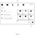
- FIG. 4 shows an example of a display of a battery management apparatus according to an embodiment disclosed herein.
- a user interface 40 of the battery management apparatus 100 may provide a button 45 for setting whether to maintain an operation mode (or a monitoring mode).
- the battery management apparatus 100 may receive a user command for activating or deactivating a fire monitoring function through a display.
- the user may select whether to maintain the battery management apparatus 100 in the operation mode or switch the battery management apparatus 100 to the sleep mode when charge of the battery is completed.
- the battery management apparatus 100 may receive a user command for activating or deactivating the fire monitoring function through the button 45.
- the operation mode may be referred to as the monitoring mode.
- FIG. 5 is a flowchart of an operating method of a battery management apparatus according to an embodiment disclosed herein.
- an operating method of the battery management apparatus 100 may include operation S110 of generating information about occurrence of fire, operation S120 of controlling charge of the battery based on power for charging the battery, supplied from a charger, operation S130 of monitoring the information about occurrence of the fire, based on power for monitoring the fire, supplied from the charger, upon completion of the charge of the battery, and operation S140 of determining whether the fire occurs, based on a monitoring result.
- the sensor 110 may sense generate the information about occurrence of the fire.
- the sensor 110 may detect at least any one of temperature, gas, voltage deviation between battery cells, generation of light, and over-voltage and over-current, and generate the information about occurrence of the fire based on the detected information.
- the sensor 110 may include at least any one of a voltage detecting sensor, a current detecting sensor, a thermistor, a temperature sensor, a light detecting sensor, and a gas sensor.
- the controller 120 may control charge of the battery based on the power for charging the battery, supplied from the charger.
- the controller 120 may monitor the information about occurrence of the fire based on the power for monitoring the fire, supplied from the charger, upon completion of the charge of the battery. For example, the controller 120 may monitor the information about occurrence of the fire, generated from the sensor 110, based on minimum power for monitoring the fire, supplied from the charger.
- the controller 120 may determine whether the fire occurs based on the monitoring result. For example, the controller 120 may determine, based on the information about occurrence of the fire, that the fire occurs in the vehicle, in at least any one case of when a temperature increases above a set value, when generated light is generated above a set value, when gas is generated above a set value, over-voltage occurs above a set value, and when a voltage deviation between battery cells is a set value or higher.
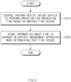
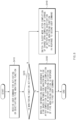
- FIGS. 6 to 8 are flowcharts of an operating method of a battery management apparatus, according to an embodiment disclosed herein.
- an operating method of the battery management apparatus 100 included in the vehicle receiving power for monitoring fire from the charger upon completion of charge may further include operation S210 of controlling another device inside the vehicle to perform an operation for preventing the fire based on whether the fire occurs, and operation S220 of storing the information about the fire in the charger or the battery management apparatus when determining that the fire occurs.
- the operating method of the battery management apparatus 100 may further include at least any one of operation S210 and operation S220.
- the controller 120 may control another device inside the vehicle to perform an operation for preventing the fire, based on whether the fire occurs.
- the controller 120 may control another device inside the vehicle to perform at least any one of a forced vent operation, a fast cooling operation, and an operation of extinguishing the fire through a water nozzle.
- the controller 120 may prevent ignition of the vehicle by shutting down all systems inside the vehicle when the fire is expected to occur.
- the controller 120 may store the information about the fire in the charger (e.g., the charger 2 of FIG. 2 ) or the battery management apparatus 100. For example, when the fire occurs, to prevent loss of data, when determining that the fire occurs, the controller 120 may store the information about the fire, collected in the sensor 110, in the battery management apparatus 100 or the charger. Depending on an embodiment, the controller 120 may transmit the information about the fire to an external server (e.g., the high-level controller 2 of FIG. 1 ).
- an external server e.g., the high-level controller 2 of FIG. 1 .
- the operating method of the battery management apparatus 100 may further include operation S310 of determining whether connection with the charger is released, upon completion of charge of the battery and operations S320 and S330 of requesting supply of power for monitoring the fire to the charger and receiving the power for monitoring the fire from the charger or switching to the sleep mode when determining that connection with the charger is released.
- the controller 120 may determine whether connection with the charger is released upon completion of the charge of the battery. For example, when energy delivered from the charger exists, the controller 120 may determine that connection with the charger is not released, and when there is no energy delivered from the charger, the controller 120 may determine that connection with the charger is released.
- the controller 120 may request supply of power for monitoring the fire to the charger and receive power for monitoring the fire from the charger, in operation S320. For example, the controller 120 may receive minimum power for monitoring the fire from the charger.
- the controller 120 may switch to the sleep mode in operation S330.
- the operating method of the battery management apparatus 100 may further include operation S410 of receiving a user command for activating or deactivating a fire monitoring function, operation S420 of determining activation or deactivation of a monitoring function, operation S430 of, upon completion of the charge of the battery during activation of the fire monitoring function in response to a first user command, monitoring the information about occurrence of the fire based on the power for monitoring the fire after completion of the charge, and operation S440 of, upon completion of the charge of the battery during deactivation of the fire monitoring function in response to a second user command, switching to a sleep mode after completion of the charge.
- the controller 120 may receive a user command for activating or deactivating the fire monitoring function.
- the controller 120 may receive a user command received from the display 130.
- the controller 120 may determine activation or deactivation of the monitoring function based on a user command.
- the controller 120 may monitor the information about occurrence of the fire based on the power for monitoring the fire after completion of the charge.
- the controller 120 may switch to the sleep mode after completion of the charge.
- FIG. 9 is a block diagram showing a hardware configuration of a computing system for performing an operating method of a battery management apparatus, according to an embodiment disclosed herein.
- a computing system 1000 may include an MCU 1010, a memory 1020, an input/output I/F 1030, and a communication I/F 1040.
- the MCU 1010 may be a processor that executes various programs (e.g., a battery pack voltage or current collection program, a relay control program, a battery fire detection program, etc.) stored in the memory 1020, processes various information including a voltage, a temperature, occurrence of fire, etc., of a battery pack through these programs, and executes the above-described functions of the battery management apparatus shown in FIG. 2 .
- programs e.g., a battery pack voltage or current collection program, a relay control program, a battery fire detection program, etc.
- the memory 1020 may store various programs regarding log information collection and diagnosis of the battery, etc.
- the memory 1020 may store various information such as a current and a voltage of the battery, and a voltage, a temperature, etc., of the battery pack.
- the memory 1020 may be provided in plural, depending on a need.
- the memory 1020 may be volatile memory or non-volatile memory.
- RAM random access memory
- DRAM dynamic RAM
- SRAM static RAM
- ROM read only memory
- PROM programmable ROM
- EAROM electrically alterable ROM
- EPROM erasable PROM
- EEPROM electrically erasable PROM
- flash memory etc.
- the above-listed examples of the memory 1020 are merely examples and are not limited thereto.
- the input/output I/F 1030 may provide an interface for transmitting and receiving data by connecting an input device (not shown) such as a keyboard, a mouse, a touch panel, etc., and an output device such as a display (not shown), etc., to the MCU 1010.
- an input device such as a keyboard, a mouse, a touch panel, etc.
- an output device such as a display (not shown), etc.
- the communication I/F 1040 which is a component capable of transmitting and receiving various data to and from a server, may be various devices capable of supporting wired or wireless communication.
- the battery management apparatus may transmit and receive a relay control program or information such as a voltage, a current, a temperature, and occurrence of fire of various battery packs from an external server separately provided through the communication I/F 1040.
- a computer program according to an embodiment disclosed herein may be recorded in the memory 1020 and processed by the MCU 1010, thus being implemented as a module that performs functions shown in FIG. 3 .
Landscapes
- Engineering & Computer Science (AREA)
- Power Engineering (AREA)
- Transportation (AREA)
- Mechanical Engineering (AREA)
- Sustainable Energy (AREA)
- Sustainable Development (AREA)
- Life Sciences & Earth Sciences (AREA)
- Chemical Kinetics & Catalysis (AREA)
- General Chemical & Material Sciences (AREA)
- Electrochemistry (AREA)
- Chemical & Material Sciences (AREA)
- Manufacturing & Machinery (AREA)
- Microelectronics & Electronic Packaging (AREA)
- Health & Medical Sciences (AREA)
- Public Health (AREA)
- Business, Economics & Management (AREA)
- Emergency Management (AREA)
- Charge And Discharge Circuits For Batteries Or The Like (AREA)
- Secondary Cells (AREA)
- Electric Propulsion And Braking For Vehicles (AREA)
Abstract
Description
- This application claims priority to and the benefit of
Korean Patent Application No. 10-2022-0019799 filed in the Korean Intellectual Property Office on February 15, 2022 - Embodiments disclosed herein relate to a battery management apparatus and an operating method thereof.
- Recently, research and development of secondary batteries have been actively performed. Herein, the secondary batteries, which are chargeable/dischargeable batteries, may include all of conventional nickel (Ni)/cadmium (Cd) batteries, Ni/metal hydride (MH) batteries, etc., and recent lithium-ion batteries. Among the secondary batteries, a lithium-ion battery has a much higher energy density than those of the conventional Ni/Cd batteries, Ni/MH batteries, etc. Moreover, the lithium-ion battery may be manufactured to be small and lightweight, such that the lithium-ion battery has been used as a power source of mobile devices, and recently, a use range thereof has been extended to power sources for electric vehicles, attracting attention as next-generation energy storage media.
- When charging a battery included in a vehicle, a user is often absent while connecting a connector to the vehicle. After completion of battery charge, all devices inside the vehicle enter a sleep mode after a preset time to prevent the vehicle from being discharged, making it difficult to collect data in case of occurrence of ignition inside the vehicle or take measures to prevent ignition.
- Embodiments disclosed herein aim to provide a battery management apparatus and an operating method thereof in which in case of occurrence of ignition inside a vehicle after completion of vehicle charge, an operation of detecting and preventing ignition may be performed.
- Embodiments disclosed herein aim to provide a battery management apparatus and an operating method thereof in which after completion of vehicle charge, minimum power may be supplied from a charging connector to enable constant monitoring of ignition inside the vehicle.
- Technical problems of the embodiments disclosed herein are not limited to the above-described technical problems, and other unmentioned technical problems would be clearly understood by one of ordinary skill in the art from the following description.
- A battery management apparatus according to an embodiment disclosed herein includes a sensor configured to generate information about occurrence of fire and a controller configured to control charge of the battery based on power for charging the battery, supplied from a charger, monitor the information about occurrence of the fire based on power for monitoring the fire, supplied from the charger, upon completion of charge of the battery, and determine whether the fire occurs based on a monitoring result.
- In an embodiment, the controller may be further configured to control another device inside the vehicle to perform an operation for preventing the fire, based on whether the fire occurs.
- In an embodiment, the controller may be further configured to store information about the fire in the charger or the battery management apparatus when determining that the fire occurs.
- In an embodiment, the controller may be further configured to receive minimum power for determining whether the fire occurs from the charger.
- In an embodiment, the controller may be further configured to determine whether connection with the charger is released, upon completion of the charge of the battery, request supply of power for monitoring the fire to the charger when determining that connection with the charger is not released, and receive the power for monitoring the fire from the charger.
- In an embodiment, the controller may be further configured to switch to a sleep mode when determining that connection with the charger is released. In an embodiment, the controller may be further configured to receive a user command for activating or deactivating a fire monitoring function, upon completion of the charge of the battery during activation of the fire monitoring function in response to a first user command, monitor the information about occurrence of the fire based on the power for monitoring the fire after completion of the charge, and upon completion of the charge of the battery during deactivation of the fire monitoring function in response to a second user command, switch to a sleep mode after completion of the charge.
- An operating method of a battery management apparatus according to an embodiment disclosed herein includes generating information about occurrence of fire, controlling charge of the battery based on power for charging the battery, supplied from a charger, monitoring the information about occurrence of the fire, based on power for monitoring the fire, supplied from the charger, upon completion of the charge of the battery, and determining whether the fire occurs, based on a monitoring result.
- In an embodiment, the operating method may further include controlling another device inside the vehicle to perform an operation for preventing the fire, based on whether the fire occurs.
- In an embodiment, the operating method may further include storing information about the fire in the charger or the battery management apparatus when determining that the fire occurs.
- In an embodiment, the operating method may further include determining whether connection with the charger is released, upon completion of the charge of the battery and requesting supply of power for monitoring the fire to the charger when determining that connection with the charger is not released, and receiving power for monitoring the fire from the charger or switching to a sleep mode when determining that connection with the charger is released.
- In an embodiment, the operating method may further include receiving a user command for activating or deactivating a fire monitoring function and upon completion of the charge of the battery during activation of the fire monitoring function in response to a first user command, monitoring the information about occurrence of the fire based on the power for monitoring the fire after completion of the charge or upon completion of the charge of the battery during deactivation of the fire monitoring function in response to a second user command, switching to a sleep mode after completion of the charge.
- A battery management apparatus and an operating method thereof according to an embodiment disclosed herein may detect ignition inside a vehicle and perform a required operation because there is no need to enter a sleep mode even when charge of the vehicle is completed.
- A battery management apparatus and an operating method thereof according to an embodiment disclosed herein may constantly monitor a state of the vehicle after completion of charge of the vehicle to collect data in case of occurrence of ignition inside the vehicle, thereby fundamentally analyzing a cause for the ignition.
- A battery management apparatus and an operating method thereof according to an embodiment disclosed herein may receive minimum power from the charger after completion of the charge of the vehicle to maintain an operation mode without entering the sleep mode, thereby detecting in advance a cause for ignition inside the vehicle and taking measures to the ignition.
- A battery management apparatus and an operating method thereof according to an embodiment disclosed herein may provide, to the user, a user interface for selecting whether to enter the sleep mode or maintain the operation mode to the user after completion of the charge of the vehicle, thereby allowing the user to make selection.
- Moreover, various effects recognized directly or indirectly from the disclosure may be provided.
-
-
FIG. 1 is a block diagram of a general battery pack. -
FIG. 2 is a view showing a vehicle including a battery management apparatus, according to an embodiment disclosed herein. -
FIG. 3 is a block diagram of a battery management apparatus according to an embodiment disclosed herein. -
FIG. 4 shows an example of a display of a battery management apparatus according to an embodiment disclosed herein. -
FIG. 5 is a flowchart of an operating method of a battery management apparatus according to an embodiment disclosed herein. -
FIGS. 6 to 8 are flowcharts of an operating method of a battery management apparatus, according to an embodiment disclosed herein. -
FIG. 9 is a block diagram showing a hardware configuration of a computing system for performing an operating method of a battery management apparatus, according to an embodiment disclosed herein. - Hereinafter, embodiments disclosed in this document will be described in detail with reference to the exemplary drawings. In adding reference numerals to components of each drawing, it should be noted that the same components are given the same reference numerals even though they are indicated in different drawings. In addition, in describing the embodiments disclosed in this document, when it is determined that a detailed description of a related known configuration or function interferes with the understanding of an embodiment disclosed in this document, the detailed description thereof will be omitted.
- To describe a component of an embodiment disclosed herein, terms such as first, second, A, B, (a), (b), etc., may be used. These terms are used merely for distinguishing one component from another component and do not limit the component to the essence, sequence, order, etc., of the component. The terms used herein, including technical and scientific terms, have the same meanings as terms that are generally understood by those skilled in the art, as long as the terms are not differently defined. Generally, the terms defined in a generally used dictionary should be interpreted as having the same meanings as the contextual meanings of the relevant technology and should not be interpreted as having ideal or exaggerated meanings unless they are clearly defined in the present application.
-
FIG. 1 is a block diagram of a general battery pack. - Referring to
FIG. 1 , a battery control system including abattery pack 1 and a higher-level controller 2 included in a higher-level system according to an embodiment of the present disclosure is schematically shown. - As shown in
FIG. 1 , thebattery pack 1 may include abattery module 10 that includes one or more battery cells and is chargeable/dischargeable, aswitching unit 14 serially connected to a positive (+) terminal side or a negative (-) terminal side of thebattery module 10 to control a charging/discharging current flow of thebattery module 10, and abattery management system 20 for control and management to prevent overcharging and over-discharging by monitoring voltage, current, temperature, etc., of thebattery pack 1. Thebattery pack 1 may include thebattery module 10, thesensor 12, theswitching unit 14, and thebattery management system 20 provided in plural. - Herein, as the
switching unit 14 which is an element for controlling a current flow for charging or discharging of the plurality ofbattery modules 10, for example, at least one relay, magnetic contactor, etc., may be used according to specifications of thebattery pack 1. - The
battery management system 20, which is an interface for receiving measurement values of the above-described various parameter values, may include a plurality of terminals and a circuit, etc., connected thereto to process input values. Thebattery management system 20 may control on/off of theswitching unit 14, e.g., a relay, a contactor, etc., and may be connected to thebattery module 10 to monitor the state of eachbattery module 10. According to an embodiment, thebattery management system 20 may include abattery management apparatus 100 ofFIG. 3 . According to another embodiment, thebattery management system 20 may be different from thebattery management apparatus 100 ofFIG. 2 . That is, thebattery management apparatus 100 ofFIG. 3 may be included in thebattery pack 1 and may be configured as another device outside thebattery pack 1. - The higher-
level controller 2 may transmit a control signal regarding thebattery module 10 to thebattery management system 20. Thus, thebattery management system 20 may also be controlled in terms of an operation thereof based on a signal applied from the higher-level controller 2. -
FIG. 2 is a view showing a vehicle including a battery management apparatus, according to an embodiment disclosed herein. - Referring to
FIG. 2 , the battery management apparatus (e.g., thebattery management apparatus 100 ofFIG. 3 ) according to an embodiment disclosed herein may be included in a vehicle 4. For example, the vehicle 4 may include means of transportation capable of including a battery such as a wheelbarrow, a two-wheeler, a tricycle, a quadricycle, an electric vehicle, an electric bicycle, a truck, a bus, etc. - The
charger 3 may charge a battery of the vehicle 4. For example, thecharger 3 may be connected to the vehicle 4 through a charging cable 5, and charge the vehicle 4. - Depending on an embodiment, the
charger 3 may continuously supply power when the vehicle 4 is completely charged. For example, the vehicle 4 may receive power for monitoring fire from thecharger 3 upon completion of charge. In another example, the vehicle 4 may receive minimum power for monitoring the fire of the vehicle 4 from thecharger 3. -
FIG. 3 is a block diagram of a battery management apparatus according to an embodiment disclosed herein. - Referring to
FIG. 3 , thebattery management apparatus 100 according to an embodiment disclosed herein may include asensor 110 and acontroller 120. Depending on an embodiment, thebattery management apparatus 100 may be included in the vehicle 4 ofFIG. 2 . Depending on an embodiment, thebattery management apparatus 100 may be included in theBMS 20 ofFIG. 1 or may be another device that is different from theBMS 20 ofFIG. 1 . - The
sensor 110 may generate information about occurrence of the fire. For example, thesensor 110 may detect at least any one of temperature, gas, voltage deviation between battery cells, generation of light, and over-voltage and over-current. In another example, thesensor 110 may include at least any one of a voltage detecting sensor, a current detecting sensor, a thermistor, a temperature sensor, a light detecting sensor, and a gas sensor. - Depending on an embodiment, the
sensor 110 may detect at least any one of battery electrolyte leakage, insulation breakdown, 2 line-to-ground fault, and pouch tear. According to another embodiment, thesensor 110 may sense at least any one of gas, pressure, current, insulating resistance, temperature, and light emission of a battery and generate information about occurrence of fire based on sensed information. - The
controller 120 may control charge of the battery based on power for charging the battery, supplied from the charger. For example, thecontroller 120 may control charge of the battery based on state information such as voltage, current, SoC, etc., of the battery. - The
controller 120 may monitor the information about occurrence of the fire, based on power for monitoring the fire, supplied from the charger, upon completion of the charge of the battery. For example, thecontroller 120 may maintain an operation mode (or a monitoring mode) based on power supplied to the vehicle upon completion of the charge of the battery, and thecontroller 120 may monitor the information about occurrence of the fire in the operation mode. For example, the operation mode may be a mode where a function of thebattery management apparatus 100 may be performed. In another example, the opposite of the operation mode may be the sleep mode, and when thecontroller 120 enters the sleep mode, the function of thecontroller 120 may not be performed. - The
controller 120 may determine whether the fire occurs, based on a monitoring result. For example, thecontroller 120 may determine, based on the information about occurrence of the fire, obtained as the monitoring result, that the fire occurs, in at least any one case of when a temperature increases above a set value, when generated light is generated above a set value, when gas is generated above a set value, over-voltage occurs above a set value, and when a voltage deviation between battery cells is a set value or higher. - The
controller 120 may control another internal device to perform an operation for preventing the fire, based on whether the fire occurs. For example, thecontroller 120 may control another device inside the vehicle to perform at least any one of a forced vent operation, a fast cooling operation, and an operation of extinguishing the fire through a water nozzle. In another example, thecontroller 120 may prevent ignition of the vehicle by shutting down all systems inside the vehicle when the fire is expected to occur. Depending on an embodiment, thecontroller 120 may determine whether the fire occurs and control another device inside the vehicle to perform an operation for preventing the fire of the vehicle. - The
controller 120 may store the information about the fire in a charger (e.g., thecharger 2 ofFIG. 2 ) or thebattery management apparatus 100 when determining that the fire occurs. For example, when the fire occurs, to prevent loss of data, when determining that the fire occurs, thecontroller 120 may store the information about the fire, collected in thesensor 110, in thebattery management apparatus 100 or the charger. Depending on an embodiment, thecontroller 120 may transmit the information about the fire to an external server (e.g., the high-level controller 2 ofFIG. 1 ). - Depending on an embodiment, the
controller 120 may receive minimum power for determining whether the fire occurs from a charger (e.g., thecharger 3 ofFIG. 2 ). - The
controller 120 may determine whether connection with the charger is released, upon completion of charge of the battery. For example, when determining that connection with the charger is not released, thecontroller 120 may request supply of power for monitoring the fire to the charger and receive power for monitoring the fire from the charger. In another example, when determining that connection with the charger is released, thecontroller 120 may switch to the sleep mode. According to an embodiment, when connection with the charger is released, it means that a user of the vehicle is present in the field, such that thecontroller 120 may switch to the sleep mode to prevent the battery from being discharged. - The
battery management apparatus 100 according to an embodiment disclosed herein may further include adisplay 130. - The
display 130 may receive a user input. For example, thedisplay 130 may provide a user interface to the user to allow the user to set whether to switch thebattery management apparatus 100 to the sleep mode. - Depending on an embodiment, the
display 130 may provide a user interface to the user to allow the user to set whether to switch thebattery management apparatus 100 to the sleep mode or maintain thebattery management apparatus 100 in the operation mode, when charge is completed. - The
controller 120 may receive a user command for activating or deactivating a fire monitoring function. For example, thecontroller 120 may receive a user command from thedisplay 130. - The
controller 120 may determine whether to activate the fire monitoring function based on the user command. For example, upon completion of the charge of the battery during activation of the fire monitoring function in response to a first user command, thecontroller 120 may monitor the information about occurrence of the fire based on the power for monitoring the fire after completion of the charge. In another example, upon completion of the charge of the battery during deactivation of the fire monitoring function in response to a second user command, thecontroller 120 may switch to the sleep mode after completion of the charge. -
FIG. 4 shows an example of a display of a battery management apparatus according to an embodiment disclosed herein. - Referring to
FIG. 4 , auser interface 40 of thebattery management apparatus 100 according to an embodiment disclosed herein may provide abutton 45 for setting whether to maintain an operation mode (or a monitoring mode). For example, thebattery management apparatus 100 may receive a user command for activating or deactivating a fire monitoring function through a display. - Depending on an embodiment, through the
button 45 for setting whether to maintain the operation mode, the user may select whether to maintain thebattery management apparatus 100 in the operation mode or switch thebattery management apparatus 100 to the sleep mode when charge of the battery is completed. - Depending on an embodiment, the
battery management apparatus 100 may receive a user command for activating or deactivating the fire monitoring function through thebutton 45. - Depending on an embodiment, the operation mode may be referred to as the monitoring mode.
-
FIG. 5 is a flowchart of an operating method of a battery management apparatus according to an embodiment disclosed herein. - Referring to
FIG. 5 , an operating method of thebattery management apparatus 100 according to an embodiment disclosed herein may include operation S110 of generating information about occurrence of fire, operation S120 of controlling charge of the battery based on power for charging the battery, supplied from a charger, operation S130 of monitoring the information about occurrence of the fire, based on power for monitoring the fire, supplied from the charger, upon completion of the charge of the battery, and operation S140 of determining whether the fire occurs, based on a monitoring result. - In operation S110 of generating the information about occurrence of the fire, the
sensor 110 may sense generate the information about occurrence of the fire. For example, thesensor 110 may detect at least any one of temperature, gas, voltage deviation between battery cells, generation of light, and over-voltage and over-current, and generate the information about occurrence of the fire based on the detected information. In another example, thesensor 110 may include at least any one of a voltage detecting sensor, a current detecting sensor, a thermistor, a temperature sensor, a light detecting sensor, and a gas sensor. - In operation S120 of controlling charge of the battery based on the power for charging the battery, supplied from the charger, the
controller 120 may control charge of the battery based on the power for charging the battery, supplied from the charger. - In operation S130 of monitoring the information about occurrence of the fire, based on power for monitoring the fire, supplied from the charger, upon completion of the charge of the battery, the
controller 120 may monitor the information about occurrence of the fire based on the power for monitoring the fire, supplied from the charger, upon completion of the charge of the battery. For example, thecontroller 120 may monitor the information about occurrence of the fire, generated from thesensor 110, based on minimum power for monitoring the fire, supplied from the charger. - In operation S140 of determining whether the fire occurs based on the monitoring result, the
controller 120 may determine whether the fire occurs based on the monitoring result. For example, thecontroller 120 may determine, based on the information about occurrence of the fire, that the fire occurs in the vehicle, in at least any one case of when a temperature increases above a set value, when generated light is generated above a set value, when gas is generated above a set value, over-voltage occurs above a set value, and when a voltage deviation between battery cells is a set value or higher. -
FIGS. 6 to 8 are flowcharts of an operating method of a battery management apparatus, according to an embodiment disclosed herein. - Referring to
FIG. 6 , an operating method of thebattery management apparatus 100 included in the vehicle receiving power for monitoring fire from the charger upon completion of charge according to an embodiment disclosed herein may further include operation S210 of controlling another device inside the vehicle to perform an operation for preventing the fire based on whether the fire occurs, and operation S220 of storing the information about the fire in the charger or the battery management apparatus when determining that the fire occurs. Depending on an embodiment, the operating method of thebattery management apparatus 100 may further include at least any one of operation S210 and operation S220. - In operation S210 of controlling another device inside the vehicle to perform an operation for preventing the fire based on whether the fire occurs, the
controller 120 may control another device inside the vehicle to perform an operation for preventing the fire, based on whether the fire occurs. For example, thecontroller 120 may control another device inside the vehicle to perform at least any one of a forced vent operation, a fast cooling operation, and an operation of extinguishing the fire through a water nozzle. In another example, thecontroller 120 may prevent ignition of the vehicle by shutting down all systems inside the vehicle when the fire is expected to occur. - In operation S220 of storing the information about the fire in the charger or the battery management apparatus when determining that the fire occurs, the
controller 120 may store the information about the fire in the charger (e.g., thecharger 2 ofFIG. 2 ) or thebattery management apparatus 100. For example, when the fire occurs, to prevent loss of data, when determining that the fire occurs, thecontroller 120 may store the information about the fire, collected in thesensor 110, in thebattery management apparatus 100 or the charger. Depending on an embodiment, thecontroller 120 may transmit the information about the fire to an external server (e.g., the high-level controller 2 ofFIG. 1 ). - Referring to
FIG. 7 , the operating method of thebattery management apparatus 100 according to an embodiment disclosed herein may further include operation S310 of determining whether connection with the charger is released, upon completion of charge of the battery and operations S320 and S330 of requesting supply of power for monitoring the fire to the charger and receiving the power for monitoring the fire from the charger or switching to the sleep mode when determining that connection with the charger is released. - In operation S310 of determining whether connection with the charger is released upon completion of the charge of the battery, the
controller 120 may determine whether connection with the charger is released upon completion of the charge of the battery. For example, when energy delivered from the charger exists, thecontroller 120 may determine that connection with the charger is not released, and when there is no energy delivered from the charger, thecontroller 120 may determine that connection with the charger is released. - When determining that connection with the charger is not released, the
controller 120 may request supply of power for monitoring the fire to the charger and receive power for monitoring the fire from the charger, in operation S320. For example, thecontroller 120 may receive minimum power for monitoring the fire from the charger. - When determining that connection with the charger is released, the
controller 120 may switch to the sleep mode in operation S330. - Referring to
FIG. 8 , the operating method of thebattery management apparatus 100 according to an embodiment disclosed herein may further include operation S410 of receiving a user command for activating or deactivating a fire monitoring function, operation S420 of determining activation or deactivation of a monitoring function, operation S430 of, upon completion of the charge of the battery during activation of the fire monitoring function in response to a first user command, monitoring the information about occurrence of the fire based on the power for monitoring the fire after completion of the charge, and operation S440 of, upon completion of the charge of the battery during deactivation of the fire monitoring function in response to a second user command, switching to a sleep mode after completion of the charge. - In operation S410 of receiving the user command for activating or deactivating the fire monitoring function, the
controller 120 may receive a user command for activating or deactivating the fire monitoring function. For example, thecontroller 120 may receive a user command received from thedisplay 130. - In operation S420 of determining activation or deactivation of the monitoring function, the
controller 120 may determine activation or deactivation of the monitoring function based on a user command. - When the user input (e.g., the first user command) for activating the monitoring function is received, in operation S430, upon completion of the charge of the battery during activation of the fire monitoring function, the
controller 120 may monitor the information about occurrence of the fire based on the power for monitoring the fire after completion of the charge. - When the user input (e.g., the second user command) for deactivating the monitoring function is received, in operation S440, upon completion of the charge of the battery during deactivation of the fire monitoring function, the
controller 120 may switch to the sleep mode after completion of the charge. -
FIG. 9 is a block diagram showing a hardware configuration of a computing system for performing an operating method of a battery management apparatus, according to an embodiment disclosed herein. - Referring to
FIG. 9 , acomputing system 1000 according to an embodiment disclosed herein may include anMCU 1010, amemory 1020, an input/output I/F 1030, and a communication I/F 1040. - The
MCU 1010 may be a processor that executes various programs (e.g., a battery pack voltage or current collection program, a relay control program, a battery fire detection program, etc.) stored in thememory 1020, processes various information including a voltage, a temperature, occurrence of fire, etc., of a battery pack through these programs, and executes the above-described functions of the battery management apparatus shown inFIG. 2 . - The
memory 1020 may store various programs regarding log information collection and diagnosis of the battery, etc. Thememory 1020 may store various information such as a current and a voltage of the battery, and a voltage, a temperature, etc., of the battery pack. - The
memory 1020 may be provided in plural, depending on a need. Thememory 1020 may be volatile memory or non-volatile memory. For thememory 1020 as the volatile memory, random access memory (RAM), dynamic RAM (DRAM), static RAM (SRAM), etc., may be used. For thememory 1020 as the nonvolatile memory, read only memory (ROM), programmable ROM (PROM), electrically alterable ROM (EAROM), erasable PROM (EPROM), electrically erasable PROM (EEPROM), flash memory, etc., may be used. The above-listed examples of thememory 1020 are merely examples and are not limited thereto. - The input/output I/
F 1030 may provide an interface for transmitting and receiving data by connecting an input device (not shown) such as a keyboard, a mouse, a touch panel, etc., and an output device such as a display (not shown), etc., to theMCU 1010. - The communication I/
F 1040, which is a component capable of transmitting and receiving various data to and from a server, may be various devices capable of supporting wired or wireless communication. For example, the battery management apparatus may transmit and receive a relay control program or information such as a voltage, a current, a temperature, and occurrence of fire of various battery packs from an external server separately provided through the communication I/F 1040. - As such, a computer program according to an embodiment disclosed herein may be recorded in the
memory 1020 and processed by theMCU 1010, thus being implemented as a module that performs functions shown inFIG. 3 . - The above description is merely illustrative of the technical idea of the present disclosure, and various modifications and variations will be possible without departing from the essential characteristics of embodiments of the present disclosure by those of ordinary skill in the art to which the embodiments disclosed herein pertains.
- Therefore, the embodiments disclosed herein are intended for description rather than limitation of the technical spirit of the embodiments disclosed herein and the scope of the technical spirit of the present disclosure is not limited by these embodiments disclosed herein. The protection scope of the technical spirit disclosed herein should be interpreted by the following claims, and all technical spirits within the same range should be understood to be included in the range of the present disclosure.
Claims (12)
- A battery management apparatus comprising:a sensor configured to generate information about occurrence of fire; anda controller configured to control charge of the battery based on power for charging the battery, supplied from a charger, monitor the information about occurrence of the fire based on power for monitoring the fire, supplied from the charger, upon completion of charge of the battery, and determine whether the fire occurs based on a monitoring result.
- The battery management apparatus of claim 1, wherein the controller is further configured to control another device inside the vehicle to perform an operation for preventing the fire, based on whether the fire occurs.
- The battery management apparatus of claim 1, wherein the controller is further configured to store information about the fire in the charger or the battery management apparatus when determining that the fire occurs.
- The battery management apparatus of claim 1, wherein the controller is further configured to receive minimum power for determining whether the fire occurs from the charger.
- The battery management apparatus of claim 1, wherein the controller is further configured to:determine whether connection with the charger is released, upon completion of the charge of the battery;request supply of power for monitoring the fire to the charger when determining that connection with the charger is not released; andreceive the power for monitoring the fire from the charger.
- The battery management apparatus of claim 5, wherein the controller is further configured to switch to a sleep mode when determining that connection with the charger is released.
- The battery management apparatus of claim 1, wherein the controller is further configured to:receive a user command for activating or deactivating a fire monitoring function;upon completion of the charge of the battery during activation of the fire monitoring function in response to a first user command, monitor the information about occurrence of the fire based on the power for monitoring the fire after completion of the charge; andupon completion of the charge of the battery during deactivation of the fire monitoring function in response to a second user command, switch to a sleep mode after completion of the charge.
- An operating method of a battery management apparatus, the operating method comprising:generating information about occurrence of fire;controlling charge of the battery based on power for charging the battery, supplied from a charger;monitoring the information about occurrence of the fire, based on power for monitoring the fire, supplied from the charger, upon completion of the charge of the battery; anddetermining whether the fire occurs, based on a monitoring result.
- The operating method of claim 8, further comprising controlling another device inside the vehicle to perform an operation for preventing the fire, based on whether the fire occurs.
- The operating method of claim 8, further comprising storing information about the fire in the charger or the battery management apparatus when determining that the fire occurs.
- The operating method of claim 8, further comprising:determining whether connection with the charger is released, upon completion of the charge of the battery; andrequesting supply of power for monitoring the fire to the charger when determining that connection with the charger is not released and receiving power for monitoring the fire from the charger, orswitching to a sleep mode when determining that connection with the charger is released.
- The operating method of claim 8, further comprising:receiving a user command for activating or deactivating a fire monitoring function; andupon completion of the charge of the battery during activation of the fire monitoring function in response to a first user command, monitoring the information about occurrence of the fire based on the power for monitoring the fire after completion of the charge, orupon completion of the charge of the battery during deactivation of the fire monitoring function in response to a second user command, switching to a sleep mode after completion of the charge.
Applications Claiming Priority (2)
| Application Number | Priority Date | Filing Date | Title |
|---|---|---|---|
| KR1020220019799A KR102965241B1 (en) | 2022-02-15 | Battery management apparatus and operating method of the same | |
| PCT/KR2022/018970 WO2023158069A1 (en) | 2022-02-15 | 2022-11-28 | Battery management apparatus and operation method therefor |
Publications (2)
| Publication Number | Publication Date |
|---|---|
| EP4461580A1 true EP4461580A1 (en) | 2024-11-13 |
| EP4461580A4 EP4461580A4 (en) | 2025-05-14 |
Family
ID=87578777
Family Applications (1)
| Application Number | Title | Priority Date | Filing Date |
|---|---|---|---|
| EP22927465.9A Pending EP4461580A4 (en) | 2022-02-15 | 2022-11-28 | Battery management apparatus and operation method therefor |
Country Status (5)
| Country | Link |
|---|---|
| US (1) | US20250170917A1 (en) |
| EP (1) | EP4461580A4 (en) |
| JP (1) | JP2025505629A (en) |
| CN (1) | CN118613383A (en) |
| WO (1) | WO2023158069A1 (en) |
Family Cites Families (17)
| Publication number | Priority date | Publication date | Assignee | Title |
|---|---|---|---|---|
| JP5124816B2 (en) * | 2008-06-25 | 2013-01-23 | 三菱自動車工業株式会社 | Electric car |
| JP5402185B2 (en) * | 2009-04-13 | 2014-01-29 | 株式会社デンソー | Charge monitoring device, electric vehicle, and server |
| JP5668541B2 (en) * | 2011-03-11 | 2015-02-12 | 日産自動車株式会社 | Vehicle charging control device |
| DK2500888T3 (en) * | 2011-03-17 | 2013-09-02 | Kapsch Trafficcom Ag | Parking space with a reservation system |
| JP5870282B2 (en) * | 2011-03-23 | 2016-02-24 | パナソニックIpマネジメント株式会社 | Charge control device and charge control system |
| JP2013074707A (en) * | 2011-09-27 | 2013-04-22 | Sanyo Electric Co Ltd | Power supply unit and vehicle including the same, and power storage device |
| KR101280004B1 (en) * | 2011-11-18 | 2013-07-05 | 자동차부품연구원 | Charging system connection type apparatus and method for managing temperature of battery |
| JP5880394B2 (en) * | 2012-10-30 | 2016-03-09 | トヨタ自動車株式会社 | Vehicle power supply |
| DE102012222070B4 (en) * | 2012-12-03 | 2024-08-14 | Robert Bosch Gmbh | Warning system for monitoring a vehicle battery |
| JP6107142B2 (en) * | 2013-01-08 | 2017-04-05 | トヨタ自動車株式会社 | POWER CONTROL DEVICE, POWER MODEL UPDATE METHOD, PROGRAM, AND MEDIUM |
| JP2014135824A (en) * | 2013-01-09 | 2014-07-24 | Sumitomo Electric Ind Ltd | Charging equipment and charging system of electric propulsion vehicle |
| KR20150091774A (en) * | 2014-02-04 | 2015-08-12 | 주식회사 수만테크 | Emergency power supply system |
| EP3988602A4 (en) | 2019-06-19 | 2023-07-05 | Mitsui Chemicals, Inc. | Use condition setting method for polymerization catalyst, polymerization condition setting method, and method for producing optical material |
| CN110265736B (en) * | 2019-06-20 | 2021-06-08 | 国电南瑞科技股份有限公司 | Energy storage power station battery management system with intelligent fire early warning function and early warning method |
| JP7545245B2 (en) * | 2020-07-13 | 2024-09-04 | 株式会社Subaru | Power Control System |
| KR102352308B1 (en) * | 2021-07-23 | 2022-01-17 | 주식회사유비씨에스 | Wake-up apparatus of battery management system |
| CN113746183A (en) * | 2021-11-05 | 2021-12-03 | 江苏易电行电动科技有限公司 | Conduction type safe and rapid charger for lithium battery electric bicycle and charging method |
-
2022
- 2022-11-28 EP EP22927465.9A patent/EP4461580A4/en active Pending
- 2022-11-28 WO PCT/KR2022/018970 patent/WO2023158069A1/en not_active Ceased
- 2022-11-28 CN CN202280090110.4A patent/CN118613383A/en active Pending
- 2022-11-28 US US18/837,242 patent/US20250170917A1/en active Pending
- 2022-11-28 JP JP2024546287A patent/JP2025505629A/en active Pending
Also Published As
| Publication number | Publication date |
|---|---|
| JP2025505629A (en) | 2025-02-28 |
| CN118613383A (en) | 2024-09-06 |
| EP4461580A4 (en) | 2025-05-14 |
| US20250170917A1 (en) | 2025-05-29 |
| KR20230122936A (en) | 2023-08-22 |
| WO2023158069A1 (en) | 2023-08-24 |
Similar Documents
| Publication | Publication Date | Title |
|---|---|---|
| EP4394407B1 (en) | Battery management device and operation method thereof | |
| EP4446760B1 (en) | Battery depth-of-charge calculation apparatus and operating method thereof | |
| US20260110739A1 (en) | Battery State Management Apparatus and Operating Method Thereof | |
| KR20240069660A (en) | Battery management apparatus and operating method of the same | |
| EP4365613B1 (en) | Battery pack and operating method thereof | |
| US20250170917A1 (en) | Battery Management Apparatus and Operating Method Thereof | |
| EP4567447A1 (en) | Battery management apparatus and operation method therefor | |
| EP4318007B1 (en) | Fire prevention appartus and operating method therefor | |
| EP4325232A1 (en) | Battery management device and operating method therefor | |
| EP4106133A1 (en) | Battery management device and method, and battery management system | |
| US20240421610A1 (en) | Battery Control System and Method for Managing Battery State | |
| KR20240162881A (en) | Battery management apparatus and operating method of the same | |
| KR102965241B1 (en) | Battery management apparatus and operating method of the same | |
| KR20240022931A (en) | Battery management apparatus and operating method of the same | |
| EP4600678A1 (en) | Battery management device and operation method therefor | |
| KR102963938B1 (en) | Apparatus for preventing battery fire and method thereof | |
| KR102966902B1 (en) | Battery cell diagnosing apparatus and operating method of the same | |
| EP4549971A1 (en) | Battery management apparatus and operating method thereof | |
| US20250149663A1 (en) | Battery Management Apparatus and Operating Method Thereof | |
| KR20250014601A (en) | Battery management apparatus and operating method of the same | |
| KR20240022930A (en) | Battery cell diagnosing apparatus and operating method of the same | |
| KR20250010934A (en) | Battery management apparatus and operating method of the same | |
| KR20240045915A (en) | Battery status managing apparatus and operating method of the same | |
| KR20250145968A (en) | Battery management apparatus and operating method thereof | |
| KR20250096400A (en) | Battery management apparatus and operating method of the same, battery pack |
Legal Events
| Date | Code | Title | Description |
|---|---|---|---|
| STAA | Information on the status of an ep patent application or granted ep patent |
Free format text: STATUS: THE INTERNATIONAL PUBLICATION HAS BEEN MADE |
|
| PUAI | Public reference made under article 153(3) epc to a published international application that has entered the european phase |
Free format text: ORIGINAL CODE: 0009012 |
|
| STAA | Information on the status of an ep patent application or granted ep patent |
Free format text: STATUS: REQUEST FOR EXAMINATION WAS MADE |
|
| 17P | Request for examination filed |
Effective date: 20240805 |
|
| AK | Designated contracting states |
Kind code of ref document: A1 Designated state(s): AL AT BE BG CH CY CZ DE DK EE ES FI FR GB GR HR HU IE IS IT LI LT LU LV MC ME MK MT NL NO PL PT RO RS SE SI SK SM TR |
|
| A4 | Supplementary search report drawn up and despatched |
Effective date: 20250414 |
|
| RIC1 | Information provided on ipc code assigned before grant |
Ipc: H01M 50/204 20210101ALI20250408BHEP Ipc: H01M 10/625 20140101ALI20250408BHEP Ipc: H01M 10/0525 20100101ALI20250408BHEP Ipc: B60L 58/15 20190101ALI20250408BHEP Ipc: B60L 53/18 20190101ALI20250408BHEP Ipc: A62C 3/07 20060101ALI20250408BHEP Ipc: B60L 58/24 20190101ALI20250408BHEP Ipc: B60L 53/68 20190101ALI20250408BHEP Ipc: B60L 53/62 20190101ALI20250408BHEP Ipc: B60L 3/12 20060101ALI20250408BHEP Ipc: B60L 53/60 20190101ALI20250408BHEP Ipc: B60L 58/12 20190101ALI20250408BHEP Ipc: B60L 3/00 20190101AFI20250408BHEP |
|
| DAV | Request for validation of the european patent (deleted) | ||
| DAX | Request for extension of the european patent (deleted) | ||
| GRAP | Despatch of communication of intention to grant a patent |
Free format text: ORIGINAL CODE: EPIDOSNIGR1 |
|
| STAA | Information on the status of an ep patent application or granted ep patent |
Free format text: STATUS: GRANT OF PATENT IS INTENDED |
|
| RIC1 | Information provided on ipc code assigned before grant |
Ipc: H01M 10/625 20140101ALI20251114BHEP Ipc: B60L 3/00 20190101AFI20251114BHEP Ipc: B60L 58/12 20190101ALI20251114BHEP Ipc: B60L 53/60 20190101ALI20251114BHEP Ipc: B60L 3/12 20060101ALI20251114BHEP Ipc: B60L 53/62 20190101ALI20251114BHEP Ipc: B60L 53/68 20190101ALI20251114BHEP Ipc: B60L 58/24 20190101ALI20251114BHEP Ipc: A62C 3/07 20060101ALI20251114BHEP Ipc: B60L 53/18 20190101ALI20251114BHEP Ipc: B60L 58/15 20190101ALI20251114BHEP Ipc: H01M 10/0525 20100101ALI20251114BHEP Ipc: H01M 50/204 20210101ALI20251114BHEP |
|
| INTG | Intention to grant announced |
Effective date: 20251222 |
|
| P01 | Opt-out of the competence of the unified patent court (upc) registered |
Free format text: CASE NUMBER: UPC_APP_0000298_4461580/2026 Effective date: 20260106 |
|
| GRAS | Grant fee paid |
Free format text: ORIGINAL CODE: EPIDOSNIGR3 |
|
| GRAA | (expected) grant |
Free format text: ORIGINAL CODE: 0009210 |
|
| STAA | Information on the status of an ep patent application or granted ep patent |
Free format text: STATUS: THE PATENT HAS BEEN GRANTED |