EP4461442A1 - Print heads for additive manufacturing apparatuses - Google Patents
Print heads for additive manufacturing apparatuses Download PDFInfo
- Publication number
- EP4461442A1 EP4461442A1 EP24174527.2A EP24174527A EP4461442A1 EP 4461442 A1 EP4461442 A1 EP 4461442A1 EP 24174527 A EP24174527 A EP 24174527A EP 4461442 A1 EP4461442 A1 EP 4461442A1
- Authority
- EP
- European Patent Office
- Prior art keywords
- print head
- laser beams
- housing
- projection element
- laser
- Prior art date
- Legal status (The legal status is an assumption and is not a legal conclusion. Google has not performed a legal analysis and makes no representation as to the accuracy of the status listed.)
- Pending
Links
Images



Classifications
-
- B—PERFORMING OPERATIONS; TRANSPORTING
- B22—CASTING; POWDER METALLURGY
- B22F—WORKING METALLIC POWDER; MANUFACTURE OF ARTICLES FROM METALLIC POWDER; MAKING METALLIC POWDER; APPARATUS OR DEVICES SPECIALLY ADAPTED FOR METALLIC POWDER
- B22F12/00—Apparatus or devices specially adapted for additive manufacturing; Auxiliary means for additive manufacturing; Combinations of additive manufacturing apparatus or devices with other processing apparatus or devices
- B22F12/40—Radiation means
- B22F12/46—Radiation means with translatory movement
- B22F12/47—Radiation means with translatory movement parallel to the deposition plane
-
- B—PERFORMING OPERATIONS; TRANSPORTING
- B22—CASTING; POWDER METALLURGY
- B22F—WORKING METALLIC POWDER; MANUFACTURE OF ARTICLES FROM METALLIC POWDER; MAKING METALLIC POWDER; APPARATUS OR DEVICES SPECIALLY ADAPTED FOR METALLIC POWDER
- B22F12/00—Apparatus or devices specially adapted for additive manufacturing; Auxiliary means for additive manufacturing; Combinations of additive manufacturing apparatus or devices with other processing apparatus or devices
- B22F12/40—Radiation means
- B22F12/44—Radiation means characterised by the configuration of the radiation means
- B22F12/45—Two or more
-
- B—PERFORMING OPERATIONS; TRANSPORTING
- B22—CASTING; POWDER METALLURGY
- B22F—WORKING METALLIC POWDER; MANUFACTURE OF ARTICLES FROM METALLIC POWDER; MAKING METALLIC POWDER; APPARATUS OR DEVICES SPECIALLY ADAPTED FOR METALLIC POWDER
- B22F10/00—Additive manufacturing of workpieces or articles from metallic powder
- B22F10/20—Direct sintering or melting
- B22F10/28—Powder bed fusion, e.g. selective laser melting [SLM] or electron beam melting [EBM]
-
- B—PERFORMING OPERATIONS; TRANSPORTING
- B22—CASTING; POWDER METALLURGY
- B22F—WORKING METALLIC POWDER; MANUFACTURE OF ARTICLES FROM METALLIC POWDER; MAKING METALLIC POWDER; APPARATUS OR DEVICES SPECIALLY ADAPTED FOR METALLIC POWDER
- B22F12/00—Apparatus or devices specially adapted for additive manufacturing; Auxiliary means for additive manufacturing; Combinations of additive manufacturing apparatus or devices with other processing apparatus or devices
- B22F12/40—Radiation means
- B22F12/41—Radiation means characterised by the type, e.g. laser or electron beam
-
- B—PERFORMING OPERATIONS; TRANSPORTING
- B22—CASTING; POWDER METALLURGY
- B22F—WORKING METALLIC POWDER; MANUFACTURE OF ARTICLES FROM METALLIC POWDER; MAKING METALLIC POWDER; APPARATUS OR DEVICES SPECIALLY ADAPTED FOR METALLIC POWDER
- B22F12/00—Apparatus or devices specially adapted for additive manufacturing; Auxiliary means for additive manufacturing; Combinations of additive manufacturing apparatus or devices with other processing apparatus or devices
- B22F12/40—Radiation means
- B22F12/44—Radiation means characterised by the configuration of the radiation means
-
- B—PERFORMING OPERATIONS; TRANSPORTING
- B33—ADDITIVE MANUFACTURING TECHNOLOGY
- B33Y—ADDITIVE MANUFACTURING, i.e. MANUFACTURING OF THREE-DIMENSIONAL [3D] OBJECTS BY ADDITIVE DEPOSITION, ADDITIVE AGGLOMERATION OR ADDITIVE LAYERING, e.g. BY 3D PRINTING, STEREOLITHOGRAPHY OR SELECTIVE LASER SINTERING
- B33Y10/00—Processes of additive manufacturing
-
- B—PERFORMING OPERATIONS; TRANSPORTING
- B33—ADDITIVE MANUFACTURING TECHNOLOGY
- B33Y—ADDITIVE MANUFACTURING, i.e. MANUFACTURING OF THREE-DIMENSIONAL [3D] OBJECTS BY ADDITIVE DEPOSITION, ADDITIVE AGGLOMERATION OR ADDITIVE LAYERING, e.g. BY 3D PRINTING, STEREOLITHOGRAPHY OR SELECTIVE LASER SINTERING
- B33Y30/00—Apparatus for additive manufacturing; Details thereof or accessories therefor
-
- G—PHYSICS
- G02—OPTICS
- G02B—OPTICAL ELEMENTS, SYSTEMS OR APPARATUS
- G02B27/00—Optical systems or apparatus not provided for by any of the groups G02B1/00 - G02B26/00, G02B30/00
- G02B27/09—Beam shaping, e.g. changing the cross-sectional area, not otherwise provided for
- G02B27/0905—Dividing and/or superposing multiple light beams
-
- G—PHYSICS
- G02—OPTICS
- G02B—OPTICAL ELEMENTS, SYSTEMS OR APPARATUS
- G02B27/00—Optical systems or apparatus not provided for by any of the groups G02B1/00 - G02B26/00, G02B30/00
- G02B27/09—Beam shaping, e.g. changing the cross-sectional area, not otherwise provided for
- G02B27/0916—Adapting the beam shape of a semiconductor light source such as a laser diode or an LED, e.g. for efficiently coupling into optical fibers
-
- G—PHYSICS
- G02—OPTICS
- G02B—OPTICAL ELEMENTS, SYSTEMS OR APPARATUS
- G02B27/00—Optical systems or apparatus not provided for by any of the groups G02B1/00 - G02B26/00, G02B30/00
- G02B27/09—Beam shaping, e.g. changing the cross-sectional area, not otherwise provided for
- G02B27/0938—Using specific optical elements
- G02B27/0944—Diffractive optical elements, e.g. gratings, holograms
-
- G—PHYSICS
- G02—OPTICS
- G02B—OPTICAL ELEMENTS, SYSTEMS OR APPARATUS
- G02B27/00—Optical systems or apparatus not provided for by any of the groups G02B1/00 - G02B26/00, G02B30/00
- G02B27/09—Beam shaping, e.g. changing the cross-sectional area, not otherwise provided for
- G02B27/0938—Using specific optical elements
- G02B27/095—Refractive optical elements
-
- G—PHYSICS
- G02—OPTICS
- G02B—OPTICAL ELEMENTS, SYSTEMS OR APPARATUS
- G02B27/00—Optical systems or apparatus not provided for by any of the groups G02B1/00 - G02B26/00, G02B30/00
- G02B27/30—Collimators
Definitions
- the present specification generally relates to additive manufacturing apparatuses and, more specifically, to self-contained print heads which deliver one or more laser beams to a build plane of the additive manufacturing apparatus.
- Additive manufacturing apparatuses may be utilized to build an object from a build material, such as organic or inorganic powders, in a layer-wise manner.
- An example of additive manufacturing processes includes laser powder bed fusion systems.
- additive manufacturing apparatuses use one or multiple scanner assemblies which each include a fiber laser, collimator, adjustable beam focus assembly, and mirrors mounted on galvanometers to focus and scan a laser beam over a build plane and melt or fuse the build material at the build plane. These scanner assemblies are expensive and are difficult to align and maintain. Consolidation rates of the build material can only be increased marginally because of the heat loads and soot that are generated by adding additional scanner assemblies.
- Embodiments described herein are directed to a self-contained print head that includes one or more light sources of various powers and/or wavelengths.
- the print head can be used in conjunction with an additive manufacturing apparatus and utilizes multiple laser beams to fuse a powdered build material instead of a traditional single beam per scanner approach. This process is more energy efficient and produces less soot in the additive manufacturing apparatus. Moreover, compared to traditional scanners, this process is less expensive, more robust, and can be calibrated prior to installation.
- the print head is modular such that a build area of the additive manufacturing apparatus can be increased by adding additional modules. Additional modules can be added without the concern of soot and with a reduction of ejected material from the weld zone because only energy sufficient to fuse powder is added.
- the print head is scalable to increase consolidation rates of the powdered build material and to increase the size of parts which may be manufactured by the additive manufacturing apparatus.
- the beam shaping, combining, steering, and delivery optics for powder processing and pre- and post-heating of the weld zone are included within the print head.
- the print head generally includes a housing, a beam emitter for generating one or more laser beams, a projection element disposed within the housing which is configured to receive the one or more laser beams and project a plurality of laser beams in a pattern, and a consolidating optic configured to consolidate the pattern of the plurality of laser beams into a consolidated pattern of laser beams.
- the beam emitter is disposed within the housing.
- the beam emitter is a laser source disposed outside of the housing and coupled to a delivery medium (e.g., a fiber) which delivers the one or more laser beams to the housing.
- the beam emitter is a laser source disposed outside of the housing and the beam emitter delivers the one or more laser beams to the housing through free space.
- the print head provides a method for delivering multiple laser beams to a build plane of an additive manufacturing apparatus.
- Various embodiments of the method for delivering multiple laser beams to a build plane and the print head and the operation of the method for delivering multiple laser beams to a build plane and the print head are described in more detail herein. Whenever possible, the same reference numerals will be used throughout the drawings to refer to the same or like parts.
- the manufacturing apparatus 10 may generally include a build area or build platform 14, a supply platform 16, a recoat assembly 18, and a printing assembly 20.
- the recoat assembly 18 and the printing assembly 20 are coupled to a rail 26 of the manufacturing apparatus 10 and are configured to translate along the rail 26 in response to an actuation of a first actuator assembly 28.
- the first actuator assembly 28 may be constructed to facilitate independent control of the recoat assembly 18 and the printing assembly 20 along a working axis 30 of the manufacturing apparatus 10.
- the working axis 30 is also referred to herein as the "longitudinal axis" (i.e., extending along the +/- X axis of the coordinate axes as depicted in the figures). This allows for the recoat assembly 18 and the printing assembly 20 to traverse the working axis 30 of the manufacturing apparatus 10 in the same direction and/or in opposite directions and for the recoat assembly 18 and the printing assembly 20 to traverse the working axis 30 of the manufacturing apparatus 10 at different speeds and/or the same speed.
- the build platform 14, the supply platform 16, the recoat assembly 18, and the printing assembly 20 are positioned in series along the working axis 30 of the manufacturing apparatus 10 between a home position 34 of the printing assembly 20, located proximate an end of the working axis 30 in the -X direction, and a home position 32 of the recoat assembly 18, located proximate an end of the working axis 30 in the +X direction.
- the build platform 14 is positioned between home position 34 of the printing assembly 20 and the supply platform 16 along the working axis 30 of the manufacturing apparatus 10.
- a second actuator assembly 36 may be constructed to facilitate independent control of the printing assembly 20 along a latitudinal axis (i.e., extending along the +/- Y axis of the coordinate axes as depicted in the figures), which is generally perpendicular to the longitudinal axis (i.e., the working axis 30).
- the first actuator assembly 28 and the second actuator assembly 36 are generally referred to as a print head position control assembly. That is, the print head position control assembly includes the first actuator assembly 28 configured to move the print head along the longitudinal axis and the second actuator assembly 36 configured to move the print head along a latitudinal axis.
- the print head position control assembly may be controlled via signals generated by a control system 38 such as an electronic control unit.
- the electronic control unit may include a processor and a non-transitory computer readable memory.
- the printing assembly 20 comprises, among other features, a support bracket 40 and one or more print heads 104.
- the support bracket 40 is movably coupled to the rail 26 and the first actuator assembly 28 of the manufacturing apparatus 10 while the print head 104 is movably coupled to the support bracket 40 via the second actuator assembly 36.
- the manufacturing apparatus 10 is used to scan a build plane 54 of one or more workpieces (not shown) positioned within the manufacturing apparatus 10 with one or more electromagnetic radiation beams 106 (e.g., a laser beam(s)) emanating from the print head 104. Moreover, the manufacturing apparatus 10 is used to additively print (i.e., using an additive manufacturing technique(s)) one or more layers on each scanned workpiece.
- electromagnetic radiation beams 106 e.g., a laser beam(s)
- additive manufacturing or “additive manufacturing techniques or processes” refer to manufacturing processes in which successive layers of material are deposited on top of each other to build-up, layer-by-layer, a three-dimensional component. The successive layers are melted or fused together to form a monolithic or integral component.
- the manufacturing apparatus 10 uses a powder bed fusion (PBF) technique, such as direct metal laser melting (DMLM) or directed metal laser sintering (DMLS).
- PPF powder bed fusion
- DMLM direct metal laser melting
- DMLS directed metal laser sintering
- layers of the workpiece are additively printed by melting or fusing a first layer of a build material or powder 48 to the build plane 54, melting or fusing a second layer of powder on top of the first layer, and so on.
- the workpiece may be additively printed by melting or fusing a single layer of powder to the build plane 54.
- the manufacturing apparatus 10 may use any other suitable additive manufacturing techniques or processes.
- the recoat assembly 18 is constructed to facilitate a distribution of the powder 48 over the build platform 14 and the supply platform 16.
- the build platform 14 is coupled to a build platform actuator 50 to facilitate raising and lowering the build platform 14 relative to the working axis 30 of the manufacturing apparatus 10 in a vertical direction (i.e., a direction parallel to the +/- Z axis of the coordinate axes depicted in the figures).
- the build platform 14 and build platform actuator 50 are positioned in a build receptacle 52 located below the working axis 30 (i.e., in the -Z direction of the coordinate axes depicted in the figures) of the manufacturing apparatus 10.
- the recoat assembly 18 fills the build receptacle 52 with powder 48 until the powder 48 forms a build plane (indicated by the depicted line) 54.
- the recoat assembly 18 spreads a layer of the powder 48 across the build plane 54.
- the layer of powder 48 is then melted or fused along the build plane 54 using the electromagnetic radiation beam(s) 106 to form a first layer(s) of a workpiece.
- the build platform 14 is lowered (e.g., as indicated by the arrow) before the recoat assembly 18 spreads another layer of the powder 48 across the build plane 54.
- This layer may then be melted or fused to the first layer(s) using the one or more laser beams 106 to form a second layer(s) of the workpiece and so on.
- the supply platform 16 is coupled to a supply platform actuator 56 to facilitate raising and lowering the supply platform 16 relative to the working axis 30 of the manufacturing apparatus 10 in a vertical direction (i.e., a direction parallel to the +/- Z axis of the coordinate axes depicted in the figures).
- the supply platform 16 and supply platform actuator 56 are positioned in a supply receptacle 58 located below the working axis 30 (i.e., in the Z direction of the coordinate axes depicted in the figures) of the manufacturing apparatus 10.
- the supply platform 16 is raised relative to the supply receptacle 58 and towards the working axis 30 of the manufacturing apparatus 10 by action of the supply platform actuator 56 after a layer of powder 48 is distributed from the supply platform 16 to the build platform 14.
- the printing assembly 20 is constructed to direct one or more laser beams 106 over the layer of powder 48 on the build platform 14 as the printing assembly 20 traverses the build platform 14 along the working axis 30 of the manufacturing apparatus 10.
- the print head 104 generates and directs the one or more laser beams 106 at the build plane 54, which allows the powder 48 spread across the build platform 14 to be melted/fused.
- each print head 104 includes a beam emitter 108. More specifically, as discussed in further detail below, the beam emitter 108 emits one or more laser beams 106 which is ultimately directed at a specific location on the build plane 54. In this respect, when additively printing the workpiece, the print head 104 scans the laser beam 106 over the portion of the build plane 54 at which it desires to melt or fuse the powder 48 to form a layer(s) of the workpiece. Moreover, as discussed in further detail below, each print head 104 may include one or more components configured to collimate, focus, and direct the emitted laser beam 106.
- the manufacturing apparatus 10 may include any suitable number of print heads 104.
- the manufacturing apparatus 10 includes one print head 104.
- the manufacturing apparatus 10 may include two print heads 104 or three or more print heads 104.
- the multiple print heads 104 can be arranged in a variety of configurations including linearly and/or staggered along the X and/or Y axis directions.
- the manufacturing apparatus 10 may further include a control system 38 communicatively coupled to the first actuator assembly 28, the second actuator assembly 36, the recoat assembly 18, and/or the printing assembly 20.
- the control system 38 is coupled to the manufacturing apparatus 10 via a communication conduit 64.
- the control system 38 may be communicatively coupled to the manufacturing apparatus 10 via various other means or systems, such as, for example, through a wireless connection.
- the control system 38 which may also be referred to as an electronic control unit, comprises a processor and a non-transitory memory that includes computer readable and executable instructions stored thereon.
- Any action of the manufacturing apparatus 10, including the actions described herein, may be caused to be performed by the computer readable and executable instructions stored in the non-transitory memory of the control system 38 when executed by the processor of the control system 38.
- one or more actuators may be actuated by the computer readable and executable instructions stored in the non-transitory memory of the control system 38 when executed by the processor of the control system 38 to cause the printing assembly 20 to operate.
- control system 38 may be further communicatively coupled to a computing device 65, optionally via a network 66, or directly via a communication link such as a wired or wireless connection.
- the computing device 65 may be configured to carry out processes such as generating executable instruction for building a component with the manufacturing apparatus 10, such as by implementing CAD or other related three-dimensional drafting and rendering systems as well as a slicing engine or the like.
- the computing device 65 may be communicatively coupled to the print head 104 via the communication conduit 64. As such, the computing device 65 may be configured to control the operation of print head 104 such that one or more laser beams 106 is generated, focused, and scanned across the build plane 54. The computing device 65 also receives data associated with the location(s) of the beam(s) 106 relative to the build platform 14 from the print head 104 as the beam(s) 106 are scanned across the build plane 54.
- the configuration of the manufacturing apparatus 10 described above and shown in FIG. 1 is provided only to place the present subject matter in an exemplary field of use.
- the present subject matter may be readily adaptable to any manner of additive manufacturing machine, including additive manufacturing machines that use different additive manufacturing techniques.
- FIG. 2 is a perspective view of a portion of a printing assembly 20 in accordance with one embodiment of the disclosure.
- the printing assembly 20 is coupled to the rail 26 of the manufacturing apparatus 10 in the manner described above.
- the portion of the printing assembly 20 shown here is the print head 104.
- the print head 104 includes a housing 130 that protects the one or more components configured to collimate, focus, and direct the emitted laser beam 106.
- a soot collection system 140 is mounted on the exterior of the housing 130 and includes one or more soot collection tubes 142a, 142b connected to one or more soot collection heads 144a, 144b, respectively.
- the soot collection heads 144a, 144b are disposed on both sides of the print head 104 and are positioned adjacent to the build plane 54 to collect soot generated during the melting/fusing of powder.
- the soot collection heads 144a, 144b also contain geometric features to provide laminar flow of process gas across the build plane 54 at a rate to remove soot but leave the surface of build plane 54 undisturbed.
- the soot collection tubes 142a, 142b subsequently transfer the soot away from the build plane 54 to an appropriate filter or collection receptacle (not shown).
- the computing device 65 may be communicatively coupled to the print head 104. As such, the computing device 65 may be configured to control the operation of the print head 104 such that the soot collection system 140 can function as described herein.
- FIG. 3 is a cross-sectional side view of one embodiment of a print head 104 in accordance with the disclosure, wherein the print head 104 is self-contained and generally includes optical components configured to collimate and focus the emitted laser beam 106 onto the build plane 54.
- the print head 104 includes one or more beam emitters 108 optically coupled to a collimator 110, which is optically coupled to a beam homogenizer 112, which is optically coupled to a turning optic 114, which is optically coupled to a projection element 116 (e.g., a special light modulator ("SLM”)), which is optically coupled to imaging optics 120, which is optically coupled to a consolidating optic 124.
- SLM special light modulator
- the beam emitter 108 is a fiber-coupled laser diode. Additional components within the self-contained print head 104 include an energy recovery device 128 which is optically coupled with the projection element 116. Each of the beam emitter 108, collimator 110, beam homogenizer 112, turning optic 114, projection element 116, imaging optics 120, consolidating optic 124, and energy recovery device 128 are at least partially mounted within the housing 130 using appropriate brackets and/or fasteners (not shown).
- the housing 130 has a front side 132, a top side 134, a back side 136, and a bottom side 138.
- the beam emitter 108 generally extends along the top side 134 of the housing 130 and is configured to generate a laser beam(s) 106 of sufficient energy to at least partially melt the powder at the build plane 54.
- the beam emitter 108 is disposed within the housing 130.
- the beam emitter is a laser source (not shown) disposed outside of the housing 130 and coupled to a delivery medium (e.g., a fiber) which delivers the one or more laser beams to the housing.
- the beam emitter 108 may include any suitable type of laser that enables manufacturing apparatus 10 to function as described herein, such as a fiber laser or fiber-delivered laser, a direct diode or fiber delivered direct diode, a Raman fiber laser, and in some embodiments a yttrium-based solid state laser or a CO 2 laser.
- print head 104 is shown and described as including a single beam emitter 108, print head 104 may include more than one beam emitter. In one embodiment, for example, print head 104 may include a first beam emitter having a first power or wavelength and a second beam emitter having a second power or wavelength different from the first laser power or wavelength, or at least two beam emitters having substantially the same power output and wavelength.
- the print head 104 may include any combination of beam emitters that enable manufacturing apparatus 10 to function as described herein.
- the computing device 65 may be communicatively coupled to the print head 104. As such, the computing device 65 may be configured to control the operation of the beam emitter 108 such that the print head 104 can function as described herein.
- the beam emitter 108 first delivers the laser beam 106 to the collimator 110 which is disposed at a distal end of the beam emitter 108 and is located adjacent to the back side 136 of the housing 130.
- the collimator 110 is configured to convert the high divergence laser beam output by the fiber-coupled beam emitter 108 into a well collimated, parallel, low divergence beam using a lens system (not shown) which is matched to the fiber-coupled beam emitter 108.
- the laser beam 106 After collimation by the collimator 110, the laser beam 106 has a round Gaussian or near-Gaussian energy distribution or profile and is delivered to the beam homogenizer 112.
- the beam homogenizer is generally disposed below the collimator 110 and is also located adjacent to the back side 136 of the housing 130.
- the beam homogenizer 112 converts the round Gaussian profile of the collimated laser beam 106 to have an even energy distribution which matches the projection element 116. In other words, after homogenization by the beam homogenizer 112, the laser beam 106 has a uniform energy distribution.
- the laser beam 106 having a uniform energy distribution is directed to the turning optic 114.
- the turning optic 114 is generally disposed below the beam homogenizer 112 and is located adjacent to the back side 136 of the housing 130.
- the turning optic 114 is a dielectric mirror or prism. The turning optic 114 redirects the laser beam 106 having a uniform energy distribution to the projection element 116.
- the projection element 116 projects a plurality of laser beams 118 having a pattern of laser light which forms an image or a line.
- the projection element 116 is generally disposed adjacent to the top side 134 of the housing 130 between the front and back sides 132, 134 thereof. Moreover, the projection element 116 is located above the turning optic 114.
- the projection element 116 is coupled to a cooling element 117 for cooling the projection element 116 from heat generated by the energy of laser beam 106.
- the projection element 116 is a digital micromirror device ("DMD").
- the projection element 116 is a liquid crystal display (“LCD”) projector, liquid crystal on silicon (“LCOS”) projector, or other SLM.
- the computing device 65 may be communicatively coupled to the print head 104. As such, the computing device 65 may be configured to control the operation of the print head 104 such that the projection element 116 can function as described herein. In particular, the computing device 65 may be configured to control the pattern of the plurality of laser beams projected by the projection element 116.
- the projection element 116 directs a portion of the laser beam 106 to an energy recovery device 128.
- the energy recovery device 128 is generally disposed adjacent to the front side 132 of the housing 130 and is located below the projection element 116.
- the energy recovery device 128 is a heat sink or heat exchanger.
- the energy recovery device 128 is configured to recover any energy which is not used by the projection element 116.
- the energy recovered by the energy recovery device 128 is used for pre- or post-heating of the powder 48.
- the energy recovery device 128 includes a photovoltaic cell (not shown) for generating electric power from the energy recovered by the energy recovery device 128 and which can be reused within the manufacturing apparatus 10.
- the energy recovery device 128 is a beam dump which removes the energy recovered by the energy recovery device 128 from the manufacturing apparatus 10.
- the imaging optic(s) 120 is made up of transmissive or reflective elements which change the magnification of the pattern formed by the plurality of laser beams 118 into a magnified pattern of laser beams 122.
- a top view of the magnified pattern of laser beams 122 is shown to form an image having a rectangular image plane "A".
- the magnified pattern of laser beams 122 may form any image having an image plane of multiple different shapes or sizes as desired.
- the imaging optic(s) 120 delivers the magnified pattern of laser beams 122 to the consolidating optic 124.
- the consolidating optic 124 is disposed below the imaging optic(s) 120 and is located adjacent to the bottom side 138 of the housing 130.
- the consolidating optic 124 is a cylindrical lens or focusing diffractive optic.
- the consolidating optic 124 is used to consolidate the magnified pattern of laser beams 122 into a consolidated pattern of laser beams 126 at the build plane 54. For example, with reference to FIG. 4 , a top view of the consolidated pattern of laser beams 126 is shown to form an image having a linear image plane "B".
- the consolidated pattern of laser beams 126 may form any image having an image plane of multiple different shapes or sizes as desired.
- the print head 104 thus scans the consolidated pattern of laser beams 126 over the portion of the build plane 54 at which it desired to melt or fuse the powder to form a layer(s) of the workpiece.
- FIG. 5 is a cross-sectional side view of another embodiment of a print head 204 in accordance with the disclosure, wherein the print head 204 is self-contained and generally includes optical components configured to collimate and focus one or more emitted beam (s) 206a-206c onto the build plane 54. It should be understood that the print head 204 can be used in conjunction with the manufacturing apparatus 10 in a substantially similar manner as print head 104 discussed above.
- print head 204 includes a plurality of beam emitters 208a-208c optically coupled to a plurality of collimators 210a, 210b, 210c, which is optically coupled to a beam homogenizer 212, which is optically coupled to a turning optic 214, which is optically coupled to a projection element 216 (e.g., an SLM), which is optically coupled to imaging optics 220, which is optically coupled to a consolidating optic 224.
- the beam homogenizer 212 is a single homogenizer configured to homogenize each laser beam 206a-206c similarly.
- the beam homogenizer 212 includes a plurality of beam homogenizers 212, where each beam homogenizer 212 is configured to separately homogenize a respective one of the laser beams 206a-206c.
- Additional components within the self-contained print head 204 include an energy recovery device 228 which is optically coupled with the projection element 216.
- Each of the plurality of beam emitters 208a-208c, plurality of collimators 210a-210c, beam homogenizer 212, turning optic 214, projection element 216, imaging optics 220, consolidating optic 224, and energy recovery device 228 are at least partially mounted within the housing 230 using appropriate brackets and/or fasteners (not shown).
- the housing 230 has a front side 232, a top side 234, a back side 236, and a bottom side 238.
- the plurality of beam emitters 208a-208c are configured to generate laser beams 206a-206c, respectively, of sufficient energy to at least partially melt the powder at the build plane 54.
- the plurality of beam emitters are generally disposed along the top side 234 of the housing 230 and are located adjacent to the back side 236 thereof.
- the beam emitters 208-208c may include any suitable type of laser that enables manufacturing apparatus 10 to function as described herein, such as a fiber laser or fiber-delivered laser, a direct diode or a fiber delivered direct diode, a Raman fiber laser, and in some embodiments a yttrium-based solid state laser or a CO 2 laser. As illustrated in FIG.
- the plurality of beam emitters 208a-208c may include a first beam emitter 208a having a first power or wavelength, a second beam emitter 208b having a second power or wavelength different from the first laser power or wavelength, and a third beam emitter 208c having a third power or wavelength different from the first and second laser powers or wavelengths.
- the plurality of beam emitters 208a-208c first deliver the laser beams 206a-206c, respectively, to the plurality of collimators 210a-210c.
- the plurality of collimators 210a-210c is generally disposed under the plurality of beam emitters 208a-208c and is located adjacent to the back side 236 of the housing 230.
- the plurality of collimators 210a-210c is configured to convert each high divergence laser beam 206a-206c output by the beam emitters 208-208c into well collimated, parallel, low divergence beams using a lens system (not shown).
- the laser beams 206a-206c After collimation by the plurality of collimators 210a-210c, the laser beams 206a-206c have a round Gaussian or near-Gaussian energy distribution or profile and are delivered to the beam homogenizer 212.
- the beam homogenizer 212 is generally disposed below the plurality of collimators 210a-210c and is located adjacent to the back side 236 of the housing 230.
- the beam homogenizer 212 converts each round Gaussian profile of the collimated beams 206a-206c to have an even energy distribution which matches the projection element 216.
- the beam homogenizer 212 combines each laser beam 206a-206c into a single laser beam 206.
- a single laser beam 206 having a uniform energy distribution is delivered to the turning optic 214.
- the turning optic 214 is generally disposed below the beam homogenizer 212 and is located adjacent to the back side 236 of the housing 230.
- the turning optic 214 is a dielectric mirror or prism. The turning optic 214 redirects the laser beam 206 having a uniform energy distribution to the projection element 216.
- the projection element 216 projects a plurality of laser beams 218 having a pattern of laser light which forms an image or a line.
- the projection element 216 is generally disposed adjacent to the top side 234 of the housing 230 between the front and back sides 232, 234 thereof.
- the projection element 216 is an SLM.
- the projection element 116 is coupled to a cooling element 217 for cooling the projection element 216 from heat generated by the energy of laser beam 206.
- the projection element 216 directs a portion of the laser beam 206 to an energy recovery device 228.
- the energy recovery device 228 is generally disposed adjacent to the front side 232 of the housing 230 and is located below the projection element 216.
- the energy recovery device 228 is a heat sink or heat exchanger.
- the energy recovery device 228 is configured to recover energy that is not used by the projection element 216.
- the energy recovered by the energy recovery device 228 is used for pre- or post-heating of the powder 48.
- the energy recovery device 228 includes a photovoltaic cell (not shown) for generating electric power from the energy recovered by the energy recovery device 228 and which can be reused within the manufacturing apparatus 10.
- the energy recovery device 228 is a beam dump which removes the energy recovered by the energy recovery device 228 from the manufacturing apparatus 10.
- the plurality of laser beams 218 generated by the projection element 216 are directed to the imaging optic(s) 220 disposed below the projection element 216.
- the imaging optic(s) 220 is made up of transmissive or reflective elements which change the magnification of the pattern formed by the plurality of laser beams 218 into a magnified pattern of laser beams 222.
- the magnified pattern of laser beams 222 may form an image similar to the magnified pattern of laser beams 122 discussed above with respect to print head 104 ( FIG. 3 ).
- the imaging optic(s) 220 delivers the magnified pattern of laser beams 222 to the consolidating optic 224.
- the consolidating optic 224 is generally disposed below the imaging optic(s) 220 and is located adjacent to the bottom side 238 of the housing 230.
- the consolidating optic 224 is a cylindrical lens or focusing diffractive optic.
- the consolidating optic 224 is used to consolidate the magnified pattern of laser beams 222 into a consolidated pattern of laser beams 226 at the build plane 54.
- the consolidated pattern of laser beams 226 may form an image similar to the consolidated pattern of laser beams 126 discussed above with respect to print head 104 ( FIG. 3 ).
- the print head 204 thus scans the consolidated pattern of laser beams 226 over the portion of the build plane 54 at which it desired to melt or fuse the powder to form a layer(s) of the workpiece.
- FIG. 6 is a cross-sectional side view of yet another embodiment of a print head 304 in accordance with the disclosure, wherein the print head 304 is self-contained and generally includes optical components configured to collimate and focus the emitted laser beam 306 onto the build plane 54 of the powder. It should be understood that the print head 304 can be used in conjunction with the manufacturing apparatus 10 in a substantially similar manner as print head 104 discussed above.
- the print head 304 includes one or more beam emitters 308 optically coupled to a turning optic 314, which is optically coupled to a beam homogenizer 312, which is optically coupled to a projection element 316 (e.g., an SLM), which is optically coupled to imaging optics 320, which is optically coupled to a consolidating optic 324.
- a turning optic 314 which is optically coupled to a beam homogenizer 312, which is optically coupled to a projection element 316 (e.g., an SLM), which is optically coupled to imaging optics 320, which is optically coupled to a consolidating optic 324.
- a projection element 316 e.g., an SLM
- the beam emitter 308 generates a free space laser beam 306 where the transmission medium is air ("free space") rather than glass (e.g., the glass in a fiber optic cable).
- the beam emitter 308 is generally disposed outside of housing 330.
- Additional components within the self-contained print head 304 include an energy recovery device 328 which is optically coupled with the projection element 316.
- Each of the beam homogenizer 312, turning optic 314, projection element 316, imaging optics 320, consolidating optic 324, and energy recovery device 328 are at least partially mounted within the housing 330 using appropriate brackets and/or fasteners (not shown).
- the housing 330 has a front side 332, a top side 334, a back side 336, and a bottom side 338.
- the beam emitter 308 is configured to generate a collimated laser beam 306 of sufficient energy to at least partially melt the powder at the build plane 54.
- the beam emitter 308 is generally disposed adjacent to the front side 332 of the housing 330.
- the beam emitter 308 may include any suitable type of laser that enables manufacturing apparatus 10 to function as described herein, such as a fiber laser or fiber-delivered laser, a direct diode or a fiber delivered direct diode, a Raman fiber laser, and in some embodiments a yttrium-based solid state laser or a CO 2 laser.
- print head 304 is shown and described as including a single beam emitter 308, print head 304 may include more than one beam emitter.
- print head 304 may include a first beam emitter having a first power or wavelength and a second beam emitter having a second power or wavelength different from the first laser power or wavelength, or at least two beam emitters having substantially the same power output and wavelength.
- the print head 304 may include any combination of beam emitters that enable manufacturing apparatus 10 to function as described herein.
- the beam emitter 308 transmits a free space laser beam 306 which is collimated (e.g., parallel rays with low divergence) using a lens system (not shown).
- the free space laser beam 306 has a round Gaussian or near-Gaussian energy distribution or profile and is delivered to the turning optic 314 which is generally disposed adjacent to the back side 336 of the housing 330 and located below the beam emitter 308.
- the turning optic 314 is a dielectric mirror or prism. The turning optic 314 redirects the free space laser beam 306 having a round Gaussian or near-Gaussian energy distribution to the beam homogenizer 312.
- the beam homogenizer 312 is generally disposed above and away (e.g., toward the front side 332 of the housing 330) from the turning optic 314.
- the beam homogenizer 312 converts the round Gaussian or near-Gaussian profile of the free space laser beam 306 to have an even energy distribution which matches the projection element 316. In other words, after homogenization by the beam homogenizer 312, the free space laser beam 306 has a uniform energy distribution.
- the free space laser beam 306 having a uniform energy distribution is directed to the projection element 316.
- the projection element 316 is generally disposed adjacent to the top side 334 of the housing 330 between the front and back sides 332, 334 thereof and is located above the beam homogenizer 312. Once the free space laser beam 306 having a uniform energy distribution reaches the projection element 316, the projection element 316 projects a plurality of laser beams 318 having a pattern of laser light which forms an image or a line.
- the projection element 316 is an SLM.
- the projection element 316 is coupled to a cooling element 317 for cooling the projection element 316 from heat generated by the energy of laser beam 306.
- the projection element 316 directs a portion of the laser beam 306 to an energy recovery device 328.
- the energy recovery device 328 is generally disposed adjacent to the front side 332 of the housing 330 and is located below the projection element 316.
- the energy recovery device 328 is a heat sink or heat exchanger.
- the energy recovery device 328 is configured to recover any energy which is not used by the projection element 316.
- the energy recovered by the energy recovery device 328 is used for pre- or post-heating of the powder 48.
- the energy recovery device 328 includes a photovoltaic cell (not shown) for generating electric power from the energy recovered by the energy recovery device 328 and which can be reused within the manufacturing apparatus 10.
- the energy recovery device 328 is a beam dump which removes the energy recovered by the energy recovery device 328 from the manufacturing apparatus 10.
- the plurality of laser beams 318 generated by the projection element 316 are directed to the imaging optic(s) 320 disposed below the projection element 316.
- the imaging optic(s) 320 is made up of transmissive or reflective elements which change the magnification of the pattern formed by the plurality of laser beams 318 into a magnified pattern of laser beams 322.
- the magnified pattern of laser beams 322 may form an image similar to the magnified pattern of laser beams 122 discussed above with respect to print head 104 ( FIG. 3 ).
- the imaging optic(s) 320 delivers the magnified pattern of laser beams 322 to the consolidating optic 324.
- the consolidating optic 324 is generally disposed below the imaging optic(s) 320 and is located adjacent to the bottom side 338 of the housing 330.
- the consolidating optic 324 is a cylindrical lens or focusing diffractive optic.
- the consolidating optic 324 is used to consolidate the magnified pattern of laser beams 322 into a consolidated pattern of laser beams 326 at the build plane 54.
- the consolidated pattern of laser beams 326 may form an image similar to the consolidated pattern of laser beams 126 discussed above with respect to print head 104 ( FIG. 3 ).
- the print head 304 thus scans the consolidated pattern of laser beams 326 over the portion of the build plane 54 at which it desired to melt or fuse the powder to form a layer(s) of the workpiece.
- FIG. 7 is a cross-sectional side view of another embodiment of a print head 404 in accordance with the disclosure, wherein the print head 404 is self-contained and generally includes optical components configured to collimate and focus the emitted laser beam 406 onto the build plane 54 of the powder.
- Print head 404 is expanded from print head 104 discussed above and includes two or more projection elements 416a, 416b placed adjacent to each other in order to increase the total print area at the build plane 54. It should be understood that the print head 404 can be used in conjunction with the manufacturing apparatus 10 in a substantially similar manner as print head 104 discussed above.
- the print head 404 includes one or more beam emitters 408 optically coupled to a collimator 410, which is optically coupled to a beam homogenizer 412, which is optically coupled to a turning optic 414, which is optically coupled to a first projection element 416a (e.g., an SLM), which is optically coupled to first imaging optics 420a, which is optically coupled to a first consolidating optic 424a.
- the turning optic 414 is also optically coupled with a second projection element 416b, which is optically coupled to second imaging optics 420b, which is optically coupled to a second consolidating optic 424b.
- the first and second projection elements 416a, 416b are each configured to redirect a portion of the laser beam 406 to an energy recovery device 428.
- Each of the beam emitter 408, collimator 410, beam homogenizer 412, turning optic 414, first and second projection elements 416a, 416b, first and second imaging optics 420a, 420b, first and second consolidating optics 424a, 424b, and energy recovery device 428 are at least partially mounted within the housing 430 using appropriate brackets and/or fasteners (not shown).
- the housing 430 has a front side 432, a top side 434, a back side 436, and a bottom side 438.
- the beam emitter 408 generally extends along the top side 434 of the housing 430 and is configured to generate a laser beam(s) 406 of sufficient energy to at least partially melt the powder at the build plane 54.
- the beam emitter 408 may include any suitable type of laser that enables manufacturing apparatus 10 to function as described herein, such as a fiber laser or fiber-delivered laser, a direct diode or a fiber delivered direct diode, a Raman fiber laser, and in some embodiments a yttrium-based solid state laser or a CO 2 laser.
- print head 404 is shown and described as including a single beam emitter 408, print head 404 may include more than one beam emitter.
- print head 404 may include a first beam emitter having a first power or wavelength and a second beam emitter having a second power or wavelength different from the first laser power or wavelength, or at least two beam emitters having substantially the same power output and wavelength.
- the print head 404 may include any combination of beam emitters that enable manufacturing apparatus 10 to function as described herein.
- the beam emitter 408, the collimator 410, the beam homogenizer 412, the turning optic 414, and the first projection element 416a are configured and operate in a substantially similar manner as the corresponding components of print head 104 discussed above.
- the operation of the turning optic 414 of print head 404 differs from the operation of turning optic 114 of print head 104 in that the turning optic 414 also directs a portion of the laser beam 406 to the second projection element 416b.
- the second projection element 416b is configured to then direct the portion of the laser beam 406 to the energy recovery device 428.
- the energy recovery device 428 is configured and operates in a substantially similar manner as the energy recovery device 128 of print head 104, except the energy recovery device 428 is further configured to receive the portion of the laser beam 406 from the second projection element 416b.
- the first and second projection elements 416a, 416b are generally disposed adjacent to the top side 434 of the housing 430 with the first projection element 416a being located toward the back side 436 of the housing 130 and the second projection element 416b being spaced apart (i.e., located toward the front side 432 of the housing 130) from the first projection element 416a. Moreover, the first and second projection elements 416a, 416b are located above the turning optic 414. In some embodiments, the first and second projection elements 416a, 416b are SLMs. The first and second projection elements 416a, 416b are also coupled to a corresponding cooling element 417a, 417b, respectively, for cooling the first and second projection elements 416a, 416b from heat generated by the energy of laser beam 406.
- each of the first and second projection elements 416a, 416b project a plurality of laser beams 418a, 418b, respectively, having a pattern of laser light which forms an image or a line.
- the plurality of laser beams 418a, 418b generated by the first and second projection elements 416a, 416b are directed to the imaging optics 420a, 420b disposed below the first and second projection elements 416a, 416b, respectively.
- the imaging optics 420a, 420b are configured and operate in a substantially similar manner as the imaging optic 120 of print head 104 discussed above.
- each magnified pattern of laser beams 422a, 422b may form an image similar to the magnified pattern of laser beams 122 discussed above with respect to print head 104 ( FIG. 3 ).
- the imaging optics 420a, 420b subsequently delivers the magnified patterns of laser beams 422a, 422b to the corresponding consolidating optics 424a, 424b.
- the consolidating optics 424a, 424b are configured and operate in a substantially similar manner as the consolidating optic 124 of print head 104 discussed above.
- the consolidating optics 424a, 424b each generate a respective consolidated pattern of laser beams 426a, 426b.
- each consolidated pattern of laser beams 426a, 426b may form an image similar to the consolidated pattern of laser beams 126 discussed above with respect to print head 104 ( FIG. 3 ).
- the print head 404 thus scans the consolidated patterns of laser beams 426a, 426b over the portion of the build plane 54 at which it desired to melt or fuse the powder to form a layer(s) of the workpiece.
- the expanded print head 404 increases the total print area at the build plane 54 compared to the total print area of the individual print head 104 discussed above.
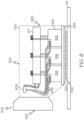
- FIG. 8 is a cross-sectional side view of yet another embodiment of a print head 504 in accordance with the disclosure, wherein the print head 504 is self-contained and generally includes optical components configured to collimate and focus the emitted beam(s) onto the build plane 54 of the powder. It should be understood that the print head 504 can be used in conjunction with the manufacturing apparatus 10 in a substantially similar manner as print head 104 discussed above.
- the print head 504 includes one or more beam emitters 508 which supply laser beams via one or more control lines 506 (e.g., fibers).
- one or more beam emitters 508 may include any suitable type of laser that enables manufacturing apparatus 10 to function as described herein, such as a fiber laser or fiber-delivered laser, a direct diode or fiber delivered direct diode, a Raman fiber laser, and in some embodiments a yttrium-based solid state laser or a CO 2 laser.
- the one or more control lines 506 each direct a laser beam to a projection element 516 (e.g., a laser diode array).
- the projection element or laser diode array 516 is made up of a plurality of print heads 518, where each print head 518 is optically coupled with one of the one or more control lines 506 to receive a laser beam therefrom.
- the one or more beam emitters 508 is a power source which supplies power via the one or more control lines 506.
- the one or more control lines 506 each direct power to the plurality of print heads 518 of laser diode array 516.
- Additional components included within the print head 504 include a heat exchanger or heat sink 517 mounted on top of the laser diode array 516 and a consolidating optic 524 disposed below the laser diode array 516.
- Each of the one or more beam emitters 508, one or more control lines 506, the laser diode array 516, the heat sink 517, and the consolidating optic 524 are at least partially mounted within a housing 530.
- the housing 530 has a front side 532, a top side 534, a back side 536, and a bottom side 538.
- the laser diode array 516 illustrated in FIG. 8 only three print heads 518 can be seen. However, it is noted that the laser diode array 516 includes an additional three print heads 518 and which are obscured from view. In this regard, the following discussion describes the configuration and operation of the laser diode array with respect to the three visible print heads 518. However, it should be understood that the three print heads 518 which are obscured from view operate in a substantially similar manner.
- the laser diode array 516 is generally disposed between the front and back sides 532, 536 of the housing 530 and is located adjacent to the bottom side 538 of the housing 530.
- the beam emitter 508 is generally disposed adjacent the front side 532 of the housing 530 and is configured to generate a laser beam(s) (not shown) of sufficient energy to at least partially melt the powder at the build plane 54.
- print head 504 is shown and described as including a single beam emitter 508, print head 504 may include more than one beam emitter.
- print head 504 may include a first beam emitter having a first power or wavelength and a second beam emitter having a second power or wavelength different from the first laser power or wavelength, or at least two beam emitters having substantially the same power output and wavelength.
- the print head 504 may include any combination of beam emitters that enable manufacturing apparatus 10 to function as described herein.
- the beam emitter 508 first delivers a laser beam through each of the one or more control lines 506 to the laser diode array 516, such that each print head 518 is optically coupled with one of the one or more control lines 506.
- the beam emitter 508 is a power supply which first delivers power through each of the one or more control lines 506 to the laser diode array 516, such that each print head 518 is electrically powered.
- the laser diode array 516 directs a portion of the laser beam to the heat sink 517.
- the heat sink 517 is configured to recover any energy which is not used by the laser diode array 516.
- the heat sink 517 acts as a cooling element for cooling the laser diode array 516 from heat generated by the energy of the laser beams (or power) delivered through the one or more control lines 506.
- Each print head 518 subsequently delivers the plurality of laser beams (not shown) having a pattern of laser light which forms an image or a line to the consolidating optic 524.
- the consolidating optic 524 is disposed below laser diode array 516 and is located adjacent to the bottom side 538 of the housing 530.
- the consolidating optic 524 is a cylindrical lens or focusing diffractive optic.
- the consolidating optic 524 is used to consolidate the plurality of laser beams (not shown) generated by each of the print heads 518 and having a pattern of laser light which forms an image or a line into a consolidated pattern of laser beams 526 at the build plane 54.
- each consolidated pattern of laser beams 526 may form an image similar to the consolidated pattern of laser beams 126 discussed above with respect to print head 104 ( FIG. 3 ).
- the print head 504 thus scans the consolidated pattern of laser beams 526 over the portion of the build plane 54 at which it desired to melt or fuse the powder to form a layer(s) of the workpiece.
- FIG. 9 is a cross-sectional side view of yet another embodiment of a print head 604 in accordance with the disclosure, wherein the print head 604 is self-contained and generally includes optical components configured to collimate and focus an emitted beam(s) (not shown) onto the build plane 54 of the powder.
- Print head 604 is expanded from print head 504 discussed above and includes a larger projection element or laser diode array 516 in order to increase the total print area at the build plane 54. It should be understood that the print head 604 can be used in conjunction with the manufacturing apparatus 10 in a substantially similar manner as print head 104 discussed above.
- the print head 604 includes one or more beam emitters 608 which supply laser beams via one or more control lines 606 (e.g., fibers).
- one or more beam emitters 608 may include any suitable type of laser that enables manufacturing apparatus 10 to function as described herein, such as a fiber laser or fiber-delivered laser, a direct diode or fiber delivered direct diode, a Raman fiber laser, and in some embodiments a yttrium-based solid state laser or a CO 2 laser.
- the one or more control lines 606 each direct a laser beam to a projection element 616 (e.g., a laser diode array).
- the projection element or laser diode array 616 is made up of a plurality of print heads 618, where each print head 618 is optically coupled with one of the one or more control lines 606 to receive a laser beam therefrom.
- the one or more beam emitters 608 is a power source which supplies power via the one or more control lines 606.
- the one or more control lines 606 each direct power to the plurality of print heads 618 of laser diode array 616.
- Additional components included within the print head 604 include a heat exchanger or heat sink 617 mounted on top of the laser diode array 616 and a consolidating optic 624 disposed below the laser diode array 616.
- Each of the one or more beam emitters 608, one or more control lines 606, the laser diode array 616, the heat sink 617, and consolidating optic 624 are at least partially mounted within a housing 630.
- the housing 630 has a front side 632, a top side 634, a back side 636, and a bottom side 638.
- the laser diode array 616 illustrated in FIG. 9 only six print heads of the plurality of print heads 618 can be seen. However, it is noted that the laser diode array 616 includes an additional six print heads which make up the plurality of print heads 618 and which are obscured from view. In this regard, the following discussion describes the configuration and operation of the laser diode array with respect to the six visible print heads of the plurality of print heads 618. However, it should be understood that the six print heads of the plurality of print heads 618 which are obscured from view operate in a substantially similar manner.
- the laser diode array 616 is generally disposed between the front and back sides 632, 636 of the housing 630 and is located adjacent to the bottom side 638 of the housing 630.
- the beam emitter 608 is generally disposed adjacent the front side 632 of the housing 630 and is configured to generate a laser beam(s) (not shown) of sufficient energy to at least partially melt the powder at the build plane 54.
- print head 604 is shown and described as including a single beam emitter 608, print head 604 may include more than one beam emitter.
- print head 604 may include a first beam emitter having a first power or wavelength and a second beam emitter having a second power or wavelength different from the first laser power or wavelength, or at least two beam emitters having substantially the same power output and wavelength.
- the print head 604 may include any combination of beam emitters that enable manufacturing apparatus 10 to function as described herein.
- the beam emitter 608 first delivers a laser beam through each of the one or more control lines 606 to the laser diode array 616, such that each print head 618 is optically coupled with one of the one or more control lines 606.
- the beam emitter 608 is a power supply which first delivers power through each of the one or more control lines 606 to the laser diode array 616, such that each print head 618 is electrically powered.
- each print head 618 projects a plurality of laser beams (not shown) having a pattern of laser light which forms an image or a line.
- the laser diode array 616 directs a portion of the laser beam to the heat sink 617.
- the heat sink 617 is configured to recover any energy which is not used by the laser diode array 616.
- the heat sink 617 acts as a cooling element for cooling the laser diode array 616 from heat generated by the energy of the laser beams (or power) delivered through the one or more control lines 606.
- Each print head 618 subsequently delivers the plurality of laser beams (not shown) having a pattern of laser light which forms an image or a line to the consolidating optic 624.
- the consolidating optic 624 is disposed below laser diode array 616 and is located adjacent to the bottom side 638 of the housing 630.
- the consolidating optic 624 is a cylindrical lens or focusing diffractive optic.
- the consolidating optic 624 is used to consolidate the plurality of laser beams (not shown) generated by each of the print heads 618 and having a pattern of laser light which forms an image or a line into a consolidated pattern of laser beams 626 at the build plane 54.
- each consolidated pattern of laser beams 626 may form an image similar to the consolidated pattern of laser beams 126 discussed above with respect to print head 104 ( FIG. 3 ).
- the print head 604 thus scans the consolidated pattern of laser beams 626 over the portion of the build plane 54 at which it is desired to melt or fuse the powder to form a layer(s) of the workpiece.
- the expanded print head 604 increases the total print area at the build plane 54 compared to the total print area of the individual print head 504 discussed above.
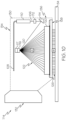
- FIG. 10 is a cross-sectional side view of another embodiment of a print head 714 in accordance with the disclosure.
- the print head 714 is similar to the print head 104 depicted in FIG. 3 . Accordingly, like numbers will be used to refer to like figures. It should be understood that the print head 714 can be used in conjunction with the manufacturing apparatus 10 in a substantially similar manner as print head 104 discussed above.
- the print head 714 is self-contained and generally includes optical components configured to collimate and focus the emitted beam 106 onto the build plane 54.
- the print head 714 includes one or more beam emitters 108 optically coupled to a collimator 110, which is optically coupled to a beam homogenizer 712.
- the beam homogenizer 712 may include a delivery optic.
- the beam homogenizer 712 is optically coupled to a turning optic 114, which is optically coupled to a projection element 716 (e.g., an SLM), which is optically coupled to an imaging optic 720.
- a projection element 716 e.g., an SLM
- the print head 714 may not include a separate consolidating optic 124 as depicted, for example, in FIG. 3 . Instead, the consolidation element may be integrated into the projection element 716.
- the projection element 716 may be a LCOS device.
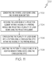
- FIG. 11 is a flow diagram of a method 700 of delivering multiple laser beams to a build plane of an manufacturing apparatus 10, as depicted in FIGS. 1-3 .
- Method 700 includes generating one or more laser beams 106 using one or more beam emitters 108 at step 702.
- Method 700 further includes receiving the laser beam 106 at a projection element 116 within a housing 130 of a print head 104 and projecting a plurality of laser beams 118 using the projection element 116 at step 704.
- Method 700 also includes consolidating the plurality of laser beams 118 into a consolidated pattern of laser beams 126 using a consolidating optic 124 within the housing 130 of the print head 104 at step 706.
- Method 400 additionally includes directing the consolidated pattern of laser beams 126 to a build plane 54 of the manufacturing apparatus 10 using the consolidating optic 124 at step 708.
- a self-contained print head that includes one or more light sources of various powers and wavelengths.
- the print head utilizes multiple laser beams to fuse a powdered build material instead of a traditional single beam per scanner approach. This process produces less soot and greater energy efficiency in the additive manufacturing apparatus. Moreover, compared to traditional scanners, this process is less expensive, more robust, and can be calibrated prior to installation.
- the print head is modular such that a build area of the additive manufacturing apparatus can be increased by adding additional modules without the concern of soot and rejected heat. As such, the print head is scalable to increase consolidation rates of the powdered build material and to increase the size of parts which may be manufactured by the additive manufacturing apparatus.
- the beam shaping, combining, steering, and delivery optics for powder processing and pre- and post-heating of the weld zone are included within the print head.
- a print head for an additive manufacturing apparatus comprising: a housing; a projection element disposed within the housing, the projection element configured to receive one or more laser beams generated by a beam emitter and project a plurality of projected laser beams in a pattern; and a consolidating optic disposed within the housing and located below the projection element, the consolidating optic configured to consolidate the pattern of the plurality of projected laser beams into a consolidated pattern of projected laser beams.
- the print head of any preceding clause further comprising a collimator disposed at a distal end of the beam emitter and within the housing, a beam homogenizer disposed below the collimator and within the housing, and a turning optic disposed below the beam homogenizer and within the housing.
- the print head of any preceding clause further comprising a heat sink disposed within the housing of the print head, wherein the projection element is further configured to direct a portion of the one or more laser beams to the heat sink disposed within the housing of the print head.
- the print head of any preceding clause further comprising a plurality of beam emitters configured to generate the one or more laser beams.
- the one or more laser beams generated by the beam emitter is a free space laser beam.
- An additive manufacturing apparatus comprising: a build platform supporting a powdered build material, the powdered build material defining a build plane on the build platform; and a print head including: a housing; a beam emitter configured to generate one or more laser beams; a projection element disposed within the housing, the projection element configured to receive the one or more laser beams and project a plurality of projected laser beams in a pattern; and a consolidating optic disposed within the housing and located below the projection element, the consolidating optic configured to consolidate the pattern of the plurality of projected laser beams into a consolidated pattern of projected laser beams; wherein the print head is configured to direct the consolidated pattern of projected laser beams over the build plane and melt a portion of the powdered build material at the build plane with the consolidated pattern of projected laser beams.
- the print head further includes a collimator disposed within the housing, wherein the collimator is optically coupled to the beam emitter.
- the print head further includes a beam homogenizer disposed within the housing, wherein the beam homogenizer is optically coupled to the collimator.
- the print head further includes a turning optic disposed within the housing, wherein the turning optic is optically coupled to the beam homogenizer and is configured to direct the one or more laser beams to the projection element.
- the print head further includes one or more imaging optics disposed within the housing, wherein the one or more imaging optics is optically coupled to the projection element.
- the projection element is a digital micromirror device.
- the additive manufacturing apparatus of any preceding clause further comprising a computing device configured to control the pattern of the plurality of projected laser beams projected by the projecting element.
- a method of delivering a plurality of laser beams onto a build plane of an additive manufacturing apparatus comprising: generating one or more laser beams with a beam emitter; receiving the one or more laser beams at a projection element disposed within a housing of a print head; projecting, by the projection element, a plurality of projected laser beams in a pattern; consolidating the pattern of the plurality of projected laser beams into a consolidated pattern of projected laser beams using a consolidating optic disposed within the housing; and directing the consolidated pattern of projected laser beams onto the build plane.
- any preceding clause further comprising collimating the one or more laser beams to have a round Gaussian energy distribution, homogenizing the one or more laser beams to have a uniform energy distribution, and redirecting the one or more laser beams having the uniform energy distribution to the projection element.
Landscapes
- Engineering & Computer Science (AREA)
- Manufacturing & Machinery (AREA)
- Materials Engineering (AREA)
- Chemical & Material Sciences (AREA)
- Toxicology (AREA)
- Health & Medical Sciences (AREA)
- General Health & Medical Sciences (AREA)
- Physics & Mathematics (AREA)
- Plasma & Fusion (AREA)
- Optics & Photonics (AREA)
- General Physics & Mathematics (AREA)
- Powder Metallurgy (AREA)
- Laser Beam Processing (AREA)
Abstract
Disclosed herein are print heads (104) for an additive manufacturing apparatus (10). The print heads (104) include a housing (130). A projection element (116) is disposed within the housing (130) and is configured to receive one or more laser beams (106) from a beam emitter (108) and project a plurality of projected laser beams (118) in a pattern (122). A consolidating optic (124) is disposed within the housing (130) and is located below the projection element (116). The consolidating optic (124) is configured to consolidate the pattern (122) of the plurality of projected laser beams (118) into a consolidated pattern of projected laser beams (126).
Description
- The present specification claims the benefit of
U.S. Provisional Patent Application Serial No. 63/465,388 filed May 10, 2023 - The present specification generally relates to additive manufacturing apparatuses and, more specifically, to self-contained print heads which deliver one or more laser beams to a build plane of the additive manufacturing apparatus.
- Additive manufacturing apparatuses may be utilized to build an object from a build material, such as organic or inorganic powders, in a layer-wise manner. An example of additive manufacturing processes includes laser powder bed fusion systems. In some applications, additive manufacturing apparatuses use one or multiple scanner assemblies which each include a fiber laser, collimator, adjustable beam focus assembly, and mirrors mounted on galvanometers to focus and scan a laser beam over a build plane and melt or fuse the build material at the build plane. These scanner assemblies are expensive and are difficult to align and maintain. Consolidation rates of the build material can only be increased marginally because of the heat loads and soot that are generated by adding additional scanner assemblies.
- Accordingly, there is a need for additive manufacturing apparatuses that include a more economical, self-contained print head utilized to manipulate multiple laser beams to melt or fuse a build material at a build plane.
- The embodiments set forth in the drawings are illustrative and exemplary in nature and not intended to limit the subject matter defined by the claims. The following detailed description of the illustrative embodiments can be understood when read in conjunction with the following drawings, where like structure is indicated with like reference numerals and in which:
-
FIG. 1 schematically depicts a side view of an additive manufacturing apparatus including a print head, according to one or more embodiments shown and described herein; -
FIG. 2 schematically depicts a perspective view of a print assembly including the print head ofFIG. 1 , according to one or more embodiments shown and described herein; -
FIG. 3 schematically depicts a side view of the print head ofFIG. 2 used with the additive manufacturing apparatus ofFIG. 1 , according to one or more embodiments shown and described herein; -
FIG. 4 schematically depicts a top view of an image plane and a consolidated image plane generated by a projection element and a consolidating optic, respectively, of the print head ofFIG. 3 , according to one or more embodiments shown and described herein; -
FIG. 5 schematically depicts a side view of another print head used with the additive manufacturing apparatus ofFIG. 1 , according to one or more embodiments shown and described herein; -
FIG. 6 schematically depicts a side view of another print head used with the additive manufacturing apparatus ofFIG. 1 , according to one or more embodiments shown and described herein; -
FIG. 7 schematically depicts a side view of another print head used with the additive manufacturing apparatus ofFIG. 1 , according to one or more embodiments shown and described herein; -
FIG. 8 schematically depicts a side view of another print head used with the additive manufacturing apparatus ofFIG. 1 , according to one or more embodiments shown and described herein; -
FIG. 9 schematically depicts a side view of another print head used with the additive manufacturing apparatus ofFIG. 1 , according to one or more embodiments shown and described herein; -
FIG. 10 schematically depicts a side view of another print head used with the additive manufacturing apparatus ofFIG. 1 , according to one or more embodiments shown and described herein; and -
FIG. 11 schematically depicts a flow chart of a method of delivering multiple laser beams to a build plane of the additive manufacturing apparatus ofFIG. 1 , according to one or more embodiments shown and described herein. - Embodiments described herein are directed to a self-contained print head that includes one or more light sources of various powers and/or wavelengths. The print head can be used in conjunction with an additive manufacturing apparatus and utilizes multiple laser beams to fuse a powdered build material instead of a traditional single beam per scanner approach. This process is more energy efficient and produces less soot in the additive manufacturing apparatus. Moreover, compared to traditional scanners, this process is less expensive, more robust, and can be calibrated prior to installation. In addition, the print head is modular such that a build area of the additive manufacturing apparatus can be increased by adding additional modules. Additional modules can be added without the concern of soot and with a reduction of ejected material from the weld zone because only energy sufficient to fuse powder is added. As such, the print head is scalable to increase consolidation rates of the powdered build material and to increase the size of parts which may be manufactured by the additive manufacturing apparatus. The beam shaping, combining, steering, and delivery optics for powder processing and pre- and post-heating of the weld zone are included within the print head.
- The print head generally includes a housing, a beam emitter for generating one or more laser beams, a projection element disposed within the housing which is configured to receive the one or more laser beams and project a plurality of laser beams in a pattern, and a consolidating optic configured to consolidate the pattern of the plurality of laser beams into a consolidated pattern of laser beams. In some embodiments, the beam emitter is disposed within the housing. In other embodiments, the beam emitter is a laser source disposed outside of the housing and coupled to a delivery medium (e.g., a fiber) which delivers the one or more laser beams to the housing. In further embodiments, the beam emitter is a laser source disposed outside of the housing and the beam emitter delivers the one or more laser beams to the housing through free space. The print head provides a method for delivering multiple laser beams to a build plane of an additive manufacturing apparatus. Various embodiments of the method for delivering multiple laser beams to a build plane and the print head and the operation of the method for delivering multiple laser beams to a build plane and the print head are described in more detail herein. Whenever possible, the same reference numerals will be used throughout the drawings to refer to the same or like parts.
- Unless otherwise expressly stated, it is in no way intended that any method set forth herein be construed as requiring that its steps be performed in a specific order, nor that with any apparatus specific orientations be required. Accordingly, where a method claim does not actually recite an order to be followed by its steps, or that any apparatus claim does not actually recite an order or orientation to individual components, or it is not otherwise specifically stated in the claims or description that the steps are to be limited to a specific order, or that a specific order or orientation to components of an apparatus is not recited, it is in no way intended that an order or orientation be inferred, in any respect. This holds for any possible non-express basis for interpretation, including: matters of logic with respect to arrangement of steps, operational flow, order of components, or orientation of components; plain meaning derived from grammatical organization or punctuation, and; the number or type of embodiments described in the specification.
- As used herein, the singular forms "a," "an" and "the" include plural referents unless the context clearly dictates otherwise. Thus, for example, reference to "a" component includes aspects having two or more such components, unless the context clearly indicates otherwise.
- Referring now to
FIG. 1 , amanufacturing apparatus 10 is illustrated according to one or more embodiments described herein. Themanufacturing apparatus 10 may generally include a build area orbuild platform 14, asupply platform 16, arecoat assembly 18, and aprinting assembly 20. Therecoat assembly 18 and theprinting assembly 20 are coupled to arail 26 of themanufacturing apparatus 10 and are configured to translate along therail 26 in response to an actuation of afirst actuator assembly 28. Thefirst actuator assembly 28 may be constructed to facilitate independent control of therecoat assembly 18 and theprinting assembly 20 along aworking axis 30 of themanufacturing apparatus 10. Theworking axis 30 is also referred to herein as the "longitudinal axis" (i.e., extending along the +/- X axis of the coordinate axes as depicted in the figures). This allows for therecoat assembly 18 and theprinting assembly 20 to traverse theworking axis 30 of themanufacturing apparatus 10 in the same direction and/or in opposite directions and for therecoat assembly 18 and theprinting assembly 20 to traverse theworking axis 30 of themanufacturing apparatus 10 at different speeds and/or the same speed. - In the embodiments described herein, the
build platform 14, thesupply platform 16, therecoat assembly 18, and theprinting assembly 20 are positioned in series along theworking axis 30 of themanufacturing apparatus 10 between ahome position 34 of theprinting assembly 20, located proximate an end of theworking axis 30 in the -X direction, and ahome position 32 of therecoat assembly 18, located proximate an end of theworking axis 30 in the +X direction. In embodiments, thebuild platform 14 is positioned betweenhome position 34 of theprinting assembly 20 and thesupply platform 16 along theworking axis 30 of themanufacturing apparatus 10. - In embodiments, a
second actuator assembly 36 may be constructed to facilitate independent control of theprinting assembly 20 along a latitudinal axis (i.e., extending along the +/- Y axis of the coordinate axes as depicted in the figures), which is generally perpendicular to the longitudinal axis (i.e., the working axis 30). Thefirst actuator assembly 28 and thesecond actuator assembly 36 are generally referred to as a print head position control assembly. That is, the print head position control assembly includes thefirst actuator assembly 28 configured to move the print head along the longitudinal axis and thesecond actuator assembly 36 configured to move the print head along a latitudinal axis. The print head position control assembly may be controlled via signals generated by acontrol system 38 such as an electronic control unit. The electronic control unit may include a processor and a non-transitory computer readable memory. - The
printing assembly 20 comprises, among other features, asupport bracket 40 and one ormore print heads 104. Thesupport bracket 40 is movably coupled to therail 26 and thefirst actuator assembly 28 of themanufacturing apparatus 10 while theprint head 104 is movably coupled to thesupport bracket 40 via thesecond actuator assembly 36. - As will be described below, the
manufacturing apparatus 10 is used to scan abuild plane 54 of one or more workpieces (not shown) positioned within themanufacturing apparatus 10 with one or more electromagnetic radiation beams 106 (e.g., a laser beam(s)) emanating from theprint head 104. Moreover, themanufacturing apparatus 10 is used to additively print (i.e., using an additive manufacturing technique(s)) one or more layers on each scanned workpiece. - As used herein, the terms "additively manufacturing" or "additive manufacturing techniques or processes" refer to manufacturing processes in which successive layers of material are deposited on top of each other to build-up, layer-by-layer, a three-dimensional component. The successive layers are melted or fused together to form a monolithic or integral component.
- In several embodiments, the
manufacturing apparatus 10 uses a powder bed fusion (PBF) technique, such as direct metal laser melting (DMLM) or directed metal laser sintering (DMLS). In such embodiments, layers of the workpiece are additively printed by melting or fusing a first layer of a build material orpowder 48 to thebuild plane 54, melting or fusing a second layer of powder on top of the first layer, and so on. However, in some embodiments, the workpiece may be additively printed by melting or fusing a single layer of powder to thebuild plane 54. Furthermore, in alternative embodiments, themanufacturing apparatus 10 may use any other suitable additive manufacturing techniques or processes. - The
recoat assembly 18 is constructed to facilitate a distribution of thepowder 48 over thebuild platform 14 and thesupply platform 16. Thebuild platform 14 is coupled to abuild platform actuator 50 to facilitate raising and lowering thebuild platform 14 relative to the workingaxis 30 of themanufacturing apparatus 10 in a vertical direction (i.e., a direction parallel to the +/- Z axis of the coordinate axes depicted in the figures). Thebuild platform 14 and buildplatform actuator 50 are positioned in abuild receptacle 52 located below the working axis 30 (i.e., in the -Z direction of the coordinate axes depicted in the figures) of themanufacturing apparatus 10. During operation of themanufacturing apparatus 10, therecoat assembly 18 fills thebuild receptacle 52 withpowder 48 until thepowder 48 forms a build plane (indicated by the depicted line) 54. Next, therecoat assembly 18 spreads a layer of thepowder 48 across thebuild plane 54. The layer ofpowder 48 is then melted or fused along thebuild plane 54 using the electromagnetic radiation beam(s) 106 to form a first layer(s) of a workpiece. Thereafter, thebuild platform 14 is lowered (e.g., as indicated by the arrow) before therecoat assembly 18 spreads another layer of thepowder 48 across thebuild plane 54. This layer may then be melted or fused to the first layer(s) using the one ormore laser beams 106 to form a second layer(s) of the workpiece and so on. - Still referring to
FIG. 1 , thesupply platform 16 is coupled to asupply platform actuator 56 to facilitate raising and lowering thesupply platform 16 relative to the workingaxis 30 of themanufacturing apparatus 10 in a vertical direction (i.e., a direction parallel to the +/- Z axis of the coordinate axes depicted in the figures). Thesupply platform 16 andsupply platform actuator 56 are positioned in asupply receptacle 58 located below the working axis 30 (i.e., in the Z direction of the coordinate axes depicted in the figures) of themanufacturing apparatus 10. During operation of themanufacturing apparatus 10, thesupply platform 16 is raised relative to thesupply receptacle 58 and towards the workingaxis 30 of themanufacturing apparatus 10 by action of thesupply platform actuator 56 after a layer ofpowder 48 is distributed from thesupply platform 16 to thebuild platform 14. - The
printing assembly 20 is constructed to direct one ormore laser beams 106 over the layer ofpowder 48 on thebuild platform 14 as theprinting assembly 20 traverses thebuild platform 14 along the workingaxis 30 of themanufacturing apparatus 10. In general, theprint head 104 generates and directs the one ormore laser beams 106 at thebuild plane 54, which allows thepowder 48 spread across thebuild platform 14 to be melted/fused. - As shown, in several embodiments, each
print head 104 includes abeam emitter 108. More specifically, as discussed in further detail below, thebeam emitter 108 emits one ormore laser beams 106 which is ultimately directed at a specific location on thebuild plane 54. In this respect, when additively printing the workpiece, theprint head 104 scans thelaser beam 106 over the portion of thebuild plane 54 at which it desires to melt or fuse thepowder 48 to form a layer(s) of the workpiece. Moreover, as discussed in further detail below, eachprint head 104 may include one or more components configured to collimate, focus, and direct the emittedlaser beam 106. - The
manufacturing apparatus 10 may include any suitable number of print heads 104. For example, in the illustrated embodiment, themanufacturing apparatus 10 includes oneprint head 104. However, in alternative embodiments, themanufacturing apparatus 10 may include twoprint heads 104 or three or more print heads 104. Themultiple print heads 104 can be arranged in a variety of configurations including linearly and/or staggered along the X and/or Y axis directions. - Still referring to
FIG. 1 , themanufacturing apparatus 10 may further include acontrol system 38 communicatively coupled to thefirst actuator assembly 28, thesecond actuator assembly 36, therecoat assembly 18, and/or theprinting assembly 20. In embodiments, thecontrol system 38 is coupled to themanufacturing apparatus 10 via acommunication conduit 64. However, it should be understood that in other embodiments thecontrol system 38 may be communicatively coupled to themanufacturing apparatus 10 via various other means or systems, such as, for example, through a wireless connection. Thecontrol system 38, which may also be referred to as an electronic control unit, comprises a processor and a non-transitory memory that includes computer readable and executable instructions stored thereon. Any action of themanufacturing apparatus 10, including the actions described herein, may be caused to be performed by the computer readable and executable instructions stored in the non-transitory memory of thecontrol system 38 when executed by the processor of thecontrol system 38. For example, one or more actuators may be actuated by the computer readable and executable instructions stored in the non-transitory memory of thecontrol system 38 when executed by the processor of thecontrol system 38 to cause theprinting assembly 20 to operate. - In embodiments, the
control system 38 may be further communicatively coupled to a computing device 65, optionally via anetwork 66, or directly via a communication link such as a wired or wireless connection. The computing device 65 may be configured to carry out processes such as generating executable instruction for building a component with themanufacturing apparatus 10, such as by implementing CAD or other related three-dimensional drafting and rendering systems as well as a slicing engine or the like. - Moreover, in some embodiments, the computing device 65 may be communicatively coupled to the
print head 104 via thecommunication conduit 64. As such, the computing device 65 may be configured to control the operation ofprint head 104 such that one ormore laser beams 106 is generated, focused, and scanned across thebuild plane 54. The computing device 65 also receives data associated with the location(s) of the beam(s) 106 relative to thebuild platform 14 from theprint head 104 as the beam(s) 106 are scanned across thebuild plane 54. - The configuration of the
manufacturing apparatus 10 described above and shown inFIG. 1 is provided only to place the present subject matter in an exemplary field of use. Thus, the present subject matter may be readily adaptable to any manner of additive manufacturing machine, including additive manufacturing machines that use different additive manufacturing techniques. -
FIG. 2 is a perspective view of a portion of aprinting assembly 20 in accordance with one embodiment of the disclosure. Theprinting assembly 20 is coupled to therail 26 of themanufacturing apparatus 10 in the manner described above. The portion of theprinting assembly 20 shown here is theprint head 104. Theprint head 104 includes ahousing 130 that protects the one or more components configured to collimate, focus, and direct the emittedlaser beam 106. Moreover, asoot collection system 140 is mounted on the exterior of thehousing 130 and includes one or moresoot collection tubes print head 104 and are positioned adjacent to thebuild plane 54 to collect soot generated during the melting/fusing of powder. The soot collection heads 144a, 144b also contain geometric features to provide laminar flow of process gas across thebuild plane 54 at a rate to remove soot but leave the surface ofbuild plane 54 undisturbed. Thesoot collection tubes build plane 54 to an appropriate filter or collection receptacle (not shown). In some embodiments, the computing device 65 may be communicatively coupled to theprint head 104. As such, the computing device 65 may be configured to control the operation of theprint head 104 such that thesoot collection system 140 can function as described herein. -
FIG. 3 is a cross-sectional side view of one embodiment of aprint head 104 in accordance with the disclosure, wherein theprint head 104 is self-contained and generally includes optical components configured to collimate and focus the emittedlaser beam 106 onto thebuild plane 54. In particular, theprint head 104 includes one ormore beam emitters 108 optically coupled to acollimator 110, which is optically coupled to abeam homogenizer 112, which is optically coupled to aturning optic 114, which is optically coupled to a projection element 116 (e.g., a special light modulator ("SLM")), which is optically coupled toimaging optics 120, which is optically coupled to a consolidatingoptic 124. In some embodiments, thebeam emitter 108 is a fiber-coupled laser diode. Additional components within the self-containedprint head 104 include anenergy recovery device 128 which is optically coupled with theprojection element 116. Each of thebeam emitter 108,collimator 110,beam homogenizer 112, turningoptic 114,projection element 116,imaging optics 120, consolidatingoptic 124, andenergy recovery device 128 are at least partially mounted within thehousing 130 using appropriate brackets and/or fasteners (not shown). Thehousing 130 has afront side 132, atop side 134, aback side 136, and abottom side 138. - The
beam emitter 108 generally extends along thetop side 134 of thehousing 130 and is configured to generate a laser beam(s) 106 of sufficient energy to at least partially melt the powder at thebuild plane 54. In some embodiments, thebeam emitter 108 is disposed within thehousing 130. In other embodiments, the beam emitter is a laser source (not shown) disposed outside of thehousing 130 and coupled to a delivery medium (e.g., a fiber) which delivers the one or more laser beams to the housing. In some embodiments, thebeam emitter 108 may include any suitable type of laser that enablesmanufacturing apparatus 10 to function as described herein, such as a fiber laser or fiber-delivered laser, a direct diode or fiber delivered direct diode, a Raman fiber laser, and in some embodiments a yttrium-based solid state laser or a CO2 laser. Further, althoughprint head 104 is shown and described as including asingle beam emitter 108,print head 104 may include more than one beam emitter. In one embodiment, for example,print head 104 may include a first beam emitter having a first power or wavelength and a second beam emitter having a second power or wavelength different from the first laser power or wavelength, or at least two beam emitters having substantially the same power output and wavelength. In yet other embodiments, theprint head 104 may include any combination of beam emitters that enablemanufacturing apparatus 10 to function as described herein. In some embodiments, the computing device 65 may be communicatively coupled to theprint head 104. As such, the computing device 65 may be configured to control the operation of thebeam emitter 108 such that theprint head 104 can function as described herein. - During operation of the
print head 104, thebeam emitter 108 first delivers thelaser beam 106 to thecollimator 110 which is disposed at a distal end of thebeam emitter 108 and is located adjacent to theback side 136 of thehousing 130. Thecollimator 110 is configured to convert the high divergence laser beam output by the fiber-coupledbeam emitter 108 into a well collimated, parallel, low divergence beam using a lens system (not shown) which is matched to the fiber-coupledbeam emitter 108. - After collimation by the
collimator 110, thelaser beam 106 has a round Gaussian or near-Gaussian energy distribution or profile and is delivered to thebeam homogenizer 112. The beam homogenizer is generally disposed below thecollimator 110 and is also located adjacent to theback side 136 of thehousing 130. Thebeam homogenizer 112 converts the round Gaussian profile of the collimatedlaser beam 106 to have an even energy distribution which matches theprojection element 116. In other words, after homogenization by thebeam homogenizer 112, thelaser beam 106 has a uniform energy distribution. - After homogenization by the
beam homogenizer 112, thelaser beam 106 having a uniform energy distribution is directed to theturning optic 114. Theturning optic 114 is generally disposed below thebeam homogenizer 112 and is located adjacent to theback side 136 of thehousing 130. In some embodiments, theturning optic 114 is a dielectric mirror or prism. Theturning optic 114 redirects thelaser beam 106 having a uniform energy distribution to theprojection element 116. - Once the
laser beam 106 having a uniform energy distribution reaches theprojection element 116, theprojection element 116 projects a plurality oflaser beams 118 having a pattern of laser light which forms an image or a line. Theprojection element 116 is generally disposed adjacent to thetop side 134 of thehousing 130 between the front andback sides projection element 116 is located above theturning optic 114. Theprojection element 116 is coupled to acooling element 117 for cooling theprojection element 116 from heat generated by the energy oflaser beam 106. In some embodiments, theprojection element 116 is a digital micromirror device ("DMD"). In other embodiments, theprojection element 116 is a liquid crystal display ("LCD") projector, liquid crystal on silicon ("LCOS") projector, or other SLM. In some embodiments, the computing device 65 may be communicatively coupled to theprint head 104. As such, the computing device 65 may be configured to control the operation of theprint head 104 such that theprojection element 116 can function as described herein. In particular, the computing device 65 may be configured to control the pattern of the plurality of laser beams projected by theprojection element 116. - Moreover, once the
laser beam 106 having a uniform energy distribution reaches theprojection element 116, theprojection element 116 directs a portion of thelaser beam 106 to anenergy recovery device 128. Theenergy recovery device 128 is generally disposed adjacent to thefront side 132 of thehousing 130 and is located below theprojection element 116. In some embodiments, theenergy recovery device 128 is a heat sink or heat exchanger. Theenergy recovery device 128 is configured to recover any energy which is not used by theprojection element 116. In some embodiments, the energy recovered by theenergy recovery device 128 is used for pre- or post-heating of thepowder 48. In other embodiments, theenergy recovery device 128 includes a photovoltaic cell (not shown) for generating electric power from the energy recovered by theenergy recovery device 128 and which can be reused within themanufacturing apparatus 10. In further embodiments, theenergy recovery device 128 is a beam dump which removes the energy recovered by theenergy recovery device 128 from themanufacturing apparatus 10. - Next, the plurality of
laser beams 118 generated by theprojection element 116 are directed to the imaging optic(s) 120 disposed below theprojection element 116. The imaging optic(s) 120 is made up of transmissive or reflective elements which change the magnification of the pattern formed by the plurality oflaser beams 118 into a magnified pattern oflaser beams 122. For example, with reference toFIG. 4 , a top view of the magnified pattern oflaser beams 122 is shown to form an image having a rectangular image plane "A". However, it should be understood that the magnified pattern oflaser beams 122 may form any image having an image plane of multiple different shapes or sizes as desired. - The imaging optic(s) 120 delivers the magnified pattern of
laser beams 122 to the consolidatingoptic 124. The consolidatingoptic 124 is disposed below the imaging optic(s) 120 and is located adjacent to thebottom side 138 of thehousing 130. In some embodiments, the consolidatingoptic 124 is a cylindrical lens or focusing diffractive optic. The consolidatingoptic 124 is used to consolidate the magnified pattern oflaser beams 122 into a consolidated pattern oflaser beams 126 at thebuild plane 54. For example, with reference toFIG. 4 , a top view of the consolidated pattern oflaser beams 126 is shown to form an image having a linear image plane "B". However, it should be understood that the consolidated pattern oflaser beams 126 may form any image having an image plane of multiple different shapes or sizes as desired. Theprint head 104 thus scans the consolidated pattern oflaser beams 126 over the portion of thebuild plane 54 at which it desired to melt or fuse the powder to form a layer(s) of the workpiece. -
FIG. 5 is a cross-sectional side view of another embodiment of aprint head 204 in accordance with the disclosure, wherein theprint head 204 is self-contained and generally includes optical components configured to collimate and focus one or more emitted beam (s) 206a-206c onto thebuild plane 54. It should be understood that theprint head 204 can be used in conjunction with themanufacturing apparatus 10 in a substantially similar manner asprint head 104 discussed above. - In particular,
print head 204 includes a plurality ofbeam emitters 208a-208c optically coupled to a plurality ofcollimators beam homogenizer 212, which is optically coupled to aturning optic 214, which is optically coupled to a projection element 216 (e.g., an SLM), which is optically coupled toimaging optics 220, which is optically coupled to a consolidating optic 224. In some embodiments, thebeam homogenizer 212 is a single homogenizer configured to homogenize eachlaser beam 206a-206c similarly. In other embodiments, thebeam homogenizer 212 includes a plurality ofbeam homogenizers 212, where eachbeam homogenizer 212 is configured to separately homogenize a respective one of thelaser beams 206a-206c. Additional components within the self-containedprint head 204 include anenergy recovery device 228 which is optically coupled with theprojection element 216. Each of the plurality ofbeam emitters 208a-208c, plurality ofcollimators 210a-210c,beam homogenizer 212, turningoptic 214,projection element 216,imaging optics 220, consolidating optic 224, andenergy recovery device 228 are at least partially mounted within thehousing 230 using appropriate brackets and/or fasteners (not shown). Thehousing 230 has afront side 232, atop side 234, aback side 236, and abottom side 238. - The plurality of
beam emitters 208a-208c are configured to generatelaser beams 206a-206c, respectively, of sufficient energy to at least partially melt the powder at thebuild plane 54. The plurality of beam emitters are generally disposed along thetop side 234 of thehousing 230 and are located adjacent to theback side 236 thereof. As inprint head 104 described above, in some embodiments, the beam emitters 208-208c may include any suitable type of laser that enablesmanufacturing apparatus 10 to function as described herein, such as a fiber laser or fiber-delivered laser, a direct diode or a fiber delivered direct diode, a Raman fiber laser, and in some embodiments a yttrium-based solid state laser or a CO2 laser. As illustrated inFIG. 5 , in some embodiments the plurality ofbeam emitters 208a-208c may include afirst beam emitter 208a having a first power or wavelength, asecond beam emitter 208b having a second power or wavelength different from the first laser power or wavelength, and athird beam emitter 208c having a third power or wavelength different from the first and second laser powers or wavelengths. - During operation of the
print head 204, the plurality ofbeam emitters 208a-208c first deliver thelaser beams 206a-206c, respectively, to the plurality ofcollimators 210a-210c. The plurality ofcollimators 210a-210c is generally disposed under the plurality ofbeam emitters 208a-208c and is located adjacent to theback side 236 of thehousing 230. The plurality ofcollimators 210a-210c is configured to convert each highdivergence laser beam 206a-206c output by the beam emitters 208-208c into well collimated, parallel, low divergence beams using a lens system (not shown). - After collimation by the plurality of
collimators 210a-210c, thelaser beams 206a-206c have a round Gaussian or near-Gaussian energy distribution or profile and are delivered to thebeam homogenizer 212. Thebeam homogenizer 212 is generally disposed below the plurality ofcollimators 210a-210c and is located adjacent to theback side 236 of thehousing 230. Thebeam homogenizer 212 converts each round Gaussian profile of the collimatedbeams 206a-206c to have an even energy distribution which matches theprojection element 216. Moreover, thebeam homogenizer 212 combines eachlaser beam 206a-206c into asingle laser beam 206. - After homogenization by the
beam homogenizer 212, asingle laser beam 206 having a uniform energy distribution is delivered to theturning optic 214. Theturning optic 214 is generally disposed below thebeam homogenizer 212 and is located adjacent to theback side 236 of thehousing 230. In some embodiments, theturning optic 214 is a dielectric mirror or prism. Theturning optic 214 redirects thelaser beam 206 having a uniform energy distribution to theprojection element 216. - Once the
laser beam 206 having a uniform energy distribution reaches theprojection element 216, theprojection element 216 projects a plurality oflaser beams 218 having a pattern of laser light which forms an image or a line. Theprojection element 216 is generally disposed adjacent to thetop side 234 of thehousing 230 between the front andback sides projection element 216 is an SLM. Theprojection element 116 is coupled to acooling element 217 for cooling theprojection element 216 from heat generated by the energy oflaser beam 206. - Moreover, once the
laser beam 206 having a uniform energy distribution reaches theprojection element 216, theprojection element 216 directs a portion of thelaser beam 206 to anenergy recovery device 228. Theenergy recovery device 228 is generally disposed adjacent to thefront side 232 of thehousing 230 and is located below theprojection element 216. In some embodiments, theenergy recovery device 228 is a heat sink or heat exchanger. Theenergy recovery device 228 is configured to recover energy that is not used by theprojection element 216. In some embodiments, the energy recovered by theenergy recovery device 228 is used for pre- or post-heating of thepowder 48. In other embodiments, theenergy recovery device 228 includes a photovoltaic cell (not shown) for generating electric power from the energy recovered by theenergy recovery device 228 and which can be reused within themanufacturing apparatus 10. In further embodiments, theenergy recovery device 228 is a beam dump which removes the energy recovered by theenergy recovery device 228 from themanufacturing apparatus 10. - Next, the plurality of
laser beams 218 generated by theprojection element 216 are directed to the imaging optic(s) 220 disposed below theprojection element 216. The imaging optic(s) 220 is made up of transmissive or reflective elements which change the magnification of the pattern formed by the plurality oflaser beams 218 into a magnified pattern oflaser beams 222. For example, the magnified pattern oflaser beams 222 may form an image similar to the magnified pattern oflaser beams 122 discussed above with respect to print head 104 (FIG. 3 ). - The imaging optic(s) 220 delivers the magnified pattern of
laser beams 222 to the consolidating optic 224. The consolidating optic 224 is generally disposed below the imaging optic(s) 220 and is located adjacent to thebottom side 238 of thehousing 230. In some embodiments, the consolidating optic 224 is a cylindrical lens or focusing diffractive optic. The consolidating optic 224 is used to consolidate the magnified pattern oflaser beams 222 into a consolidated pattern oflaser beams 226 at thebuild plane 54. For example, the consolidated pattern oflaser beams 226 may form an image similar to the consolidated pattern oflaser beams 126 discussed above with respect to print head 104 (FIG. 3 ). Theprint head 204 thus scans the consolidated pattern oflaser beams 226 over the portion of thebuild plane 54 at which it desired to melt or fuse the powder to form a layer(s) of the workpiece. -
FIG. 6 is a cross-sectional side view of yet another embodiment of aprint head 304 in accordance with the disclosure, wherein theprint head 304 is self-contained and generally includes optical components configured to collimate and focus the emittedlaser beam 306 onto thebuild plane 54 of the powder. It should be understood that theprint head 304 can be used in conjunction with themanufacturing apparatus 10 in a substantially similar manner asprint head 104 discussed above. - In particular, the
print head 304 includes one ormore beam emitters 308 optically coupled to aturning optic 314, which is optically coupled to abeam homogenizer 312, which is optically coupled to a projection element 316 (e.g., an SLM), which is optically coupled toimaging optics 320, which is optically coupled to a consolidating optic 324. - In some embodiments, the
beam emitter 308 generates a freespace laser beam 306 where the transmission medium is air ("free space") rather than glass (e.g., the glass in a fiber optic cable). In such embodiments, thebeam emitter 308 is generally disposed outside ofhousing 330. Additional components within the self-containedprint head 304 include anenergy recovery device 328 which is optically coupled with theprojection element 316. Each of thebeam homogenizer 312, turningoptic 314,projection element 316,imaging optics 320, consolidating optic 324, andenergy recovery device 328 are at least partially mounted within thehousing 330 using appropriate brackets and/or fasteners (not shown). Thehousing 330 has afront side 332, atop side 334, aback side 336, and abottom side 338. - The
beam emitter 308 is configured to generate acollimated laser beam 306 of sufficient energy to at least partially melt the powder at thebuild plane 54. Thebeam emitter 308 is generally disposed adjacent to thefront side 332 of thehousing 330. In some embodiments, thebeam emitter 308 may include any suitable type of laser that enablesmanufacturing apparatus 10 to function as described herein, such as a fiber laser or fiber-delivered laser, a direct diode or a fiber delivered direct diode, a Raman fiber laser, and in some embodiments a yttrium-based solid state laser or a CO2 laser. Further, althoughprint head 304 is shown and described as including asingle beam emitter 308,print head 304 may include more than one beam emitter. In one embodiment, for example,print head 304 may include a first beam emitter having a first power or wavelength and a second beam emitter having a second power or wavelength different from the first laser power or wavelength, or at least two beam emitters having substantially the same power output and wavelength. In yet other embodiments, theprint head 304 may include any combination of beam emitters that enablemanufacturing apparatus 10 to function as described herein. - During operation of the
print head 304, thebeam emitter 308 transmits a freespace laser beam 306 which is collimated (e.g., parallel rays with low divergence) using a lens system (not shown). The freespace laser beam 306 has a round Gaussian or near-Gaussian energy distribution or profile and is delivered to theturning optic 314 which is generally disposed adjacent to theback side 336 of thehousing 330 and located below thebeam emitter 308. In some embodiments, theturning optic 314 is a dielectric mirror or prism. Theturning optic 314 redirects the freespace laser beam 306 having a round Gaussian or near-Gaussian energy distribution to thebeam homogenizer 312. - The
beam homogenizer 312 is generally disposed above and away (e.g., toward thefront side 332 of the housing 330) from theturning optic 314. Thebeam homogenizer 312 converts the round Gaussian or near-Gaussian profile of the freespace laser beam 306 to have an even energy distribution which matches theprojection element 316. In other words, after homogenization by thebeam homogenizer 312, the freespace laser beam 306 has a uniform energy distribution. - After homogenization by the
beam homogenizer 312, the freespace laser beam 306 having a uniform energy distribution is directed to theprojection element 316. Theprojection element 316 is generally disposed adjacent to thetop side 334 of thehousing 330 between the front andback sides beam homogenizer 312. Once the freespace laser beam 306 having a uniform energy distribution reaches theprojection element 316, theprojection element 316 projects a plurality oflaser beams 318 having a pattern of laser light which forms an image or a line. In some embodiments, theprojection element 316 is an SLM. Theprojection element 316 is coupled to acooling element 317 for cooling theprojection element 316 from heat generated by the energy oflaser beam 306. - Moreover, once the free
space laser beam 306 having a uniform energy distribution reaches theprojection element 316, theprojection element 316 directs a portion of thelaser beam 306 to anenergy recovery device 328. Theenergy recovery device 328 is generally disposed adjacent to thefront side 332 of thehousing 330 and is located below theprojection element 316. In some embodiments, theenergy recovery device 328 is a heat sink or heat exchanger. Theenergy recovery device 328 is configured to recover any energy which is not used by theprojection element 316. In some embodiments, the energy recovered by theenergy recovery device 328 is used for pre- or post-heating of thepowder 48. In other embodiments, theenergy recovery device 328 includes a photovoltaic cell (not shown) for generating electric power from the energy recovered by theenergy recovery device 328 and which can be reused within themanufacturing apparatus 10. In further embodiments, theenergy recovery device 328 is a beam dump which removes the energy recovered by theenergy recovery device 328 from themanufacturing apparatus 10. - Next, the plurality of
laser beams 318 generated by theprojection element 316 are directed to the imaging optic(s) 320 disposed below theprojection element 316. The imaging optic(s) 320 is made up of transmissive or reflective elements which change the magnification of the pattern formed by the plurality oflaser beams 318 into a magnified pattern oflaser beams 322. For example, the magnified pattern oflaser beams 322 may form an image similar to the magnified pattern oflaser beams 122 discussed above with respect to print head 104 (FIG. 3 ). - The imaging optic(s) 320 delivers the magnified pattern of
laser beams 322 to the consolidating optic 324. The consolidating optic 324 is generally disposed below the imaging optic(s) 320 and is located adjacent to thebottom side 338 of thehousing 330. In some embodiments, the consolidating optic 324 is a cylindrical lens or focusing diffractive optic. The consolidating optic 324 is used to consolidate the magnified pattern oflaser beams 322 into a consolidated pattern oflaser beams 326 at thebuild plane 54. For example, the consolidated pattern oflaser beams 326 may form an image similar to the consolidated pattern oflaser beams 126 discussed above with respect to print head 104 (FIG. 3 ). Theprint head 304 thus scans the consolidated pattern oflaser beams 326 over the portion of thebuild plane 54 at which it desired to melt or fuse the powder to form a layer(s) of the workpiece. -
FIG. 7 is a cross-sectional side view of another embodiment of aprint head 404 in accordance with the disclosure, wherein theprint head 404 is self-contained and generally includes optical components configured to collimate and focus the emittedlaser beam 406 onto thebuild plane 54 of the powder.Print head 404 is expanded fromprint head 104 discussed above and includes two ormore projection elements build plane 54. It should be understood that theprint head 404 can be used in conjunction with themanufacturing apparatus 10 in a substantially similar manner asprint head 104 discussed above. - In particular, the
print head 404 includes one ormore beam emitters 408 optically coupled to acollimator 410, which is optically coupled to abeam homogenizer 412, which is optically coupled to a turning optic 414, which is optically coupled to afirst projection element 416a (e.g., an SLM), which is optically coupled tofirst imaging optics 420a, which is optically coupled to a first consolidatingoptic 424a. Moreover, the turning optic 414 is also optically coupled with asecond projection element 416b, which is optically coupled tosecond imaging optics 420b, which is optically coupled to a second consolidatingoptic 424b. The first andsecond projection elements laser beam 406 to anenergy recovery device 428. - Each of the
beam emitter 408,collimator 410,beam homogenizer 412, turning optic 414, first andsecond projection elements second imaging optics optics energy recovery device 428 are at least partially mounted within thehousing 430 using appropriate brackets and/or fasteners (not shown).Thehousing 430 has afront side 432, atop side 434, aback side 436, and abottom side 438. - The
beam emitter 408 generally extends along thetop side 434 of thehousing 430 and is configured to generate a laser beam(s) 406 of sufficient energy to at least partially melt the powder at thebuild plane 54. In some embodiments, thebeam emitter 408 may include any suitable type of laser that enablesmanufacturing apparatus 10 to function as described herein, such as a fiber laser or fiber-delivered laser, a direct diode or a fiber delivered direct diode, a Raman fiber laser, and in some embodiments a yttrium-based solid state laser or a CO2 laser. Further, althoughprint head 404 is shown and described as including asingle beam emitter 408,print head 404 may include more than one beam emitter. In one embodiment, for example,print head 404 may include a first beam emitter having a first power or wavelength and a second beam emitter having a second power or wavelength different from the first laser power or wavelength, or at least two beam emitters having substantially the same power output and wavelength. In yet other embodiments, theprint head 404 may include any combination of beam emitters that enablemanufacturing apparatus 10 to function as described herein. - During operation of the
print head 404, thebeam emitter 408, thecollimator 410, thebeam homogenizer 412, the turning optic 414, and thefirst projection element 416a are configured and operate in a substantially similar manner as the corresponding components ofprint head 104 discussed above. The operation of the turning optic 414 ofprint head 404 differs from the operation of turningoptic 114 ofprint head 104 in that the turning optic 414 also directs a portion of thelaser beam 406 to thesecond projection element 416b. Thesecond projection element 416b is configured to then direct the portion of thelaser beam 406 to theenergy recovery device 428. In turn, theenergy recovery device 428 is configured and operates in a substantially similar manner as theenergy recovery device 128 ofprint head 104, except theenergy recovery device 428 is further configured to receive the portion of thelaser beam 406 from thesecond projection element 416b. - The first and
second projection elements top side 434 of thehousing 430 with thefirst projection element 416a being located toward theback side 436 of thehousing 130 and thesecond projection element 416b being spaced apart (i.e., located toward thefront side 432 of the housing 130) from thefirst projection element 416a. Moreover, the first andsecond projection elements second projection elements second projection elements corresponding cooling element 417a, 417b, respectively, for cooling the first andsecond projection elements laser beam 406. - Once the
laser beam 406 reaches the first andsecond projection elements second projection elements laser beams laser beams second projection elements imaging optics second projection elements imaging optics imaging optic 120 ofprint head 104 discussed above. Thus, theimaging optics laser beams laser beams laser beams 122 discussed above with respect to print head 104 (FIG. 3 ). - The
imaging optics laser beams optics optics optic 124 ofprint head 104 discussed above. Thus, the consolidatingoptics laser beams laser beams laser beams 126 discussed above with respect to print head 104 (FIG. 3 ). Theprint head 404 thus scans the consolidated patterns oflaser beams build plane 54 at which it desired to melt or fuse the powder to form a layer(s) of the workpiece. In this regard, the expandedprint head 404 increases the total print area at thebuild plane 54 compared to the total print area of theindividual print head 104 discussed above. -
FIG. 8 is a cross-sectional side view of yet another embodiment of aprint head 504 in accordance with the disclosure, wherein theprint head 504 is self-contained and generally includes optical components configured to collimate and focus the emitted beam(s) onto thebuild plane 54 of the powder. It should be understood that theprint head 504 can be used in conjunction with themanufacturing apparatus 10 in a substantially similar manner asprint head 104 discussed above. - In particular, the
print head 504 includes one ormore beam emitters 508 which supply laser beams via one or more control lines 506 (e.g., fibers). In some embodiments, one ormore beam emitters 508 may include any suitable type of laser that enablesmanufacturing apparatus 10 to function as described herein, such as a fiber laser or fiber-delivered laser, a direct diode or fiber delivered direct diode, a Raman fiber laser, and in some embodiments a yttrium-based solid state laser or a CO2 laser. The one ormore control lines 506 each direct a laser beam to a projection element 516 (e.g., a laser diode array). The projection element orlaser diode array 516 is made up of a plurality of print heads 518, where eachprint head 518 is optically coupled with one of the one ormore control lines 506 to receive a laser beam therefrom. In other embodiments, the one ormore beam emitters 508 is a power source which supplies power via the one ormore control lines 506. The one ormore control lines 506 each direct power to the plurality ofprint heads 518 oflaser diode array 516. - Additional components included within the
print head 504 include a heat exchanger orheat sink 517 mounted on top of thelaser diode array 516 and a consolidatingoptic 524 disposed below thelaser diode array 516. Each of the one ormore beam emitters 508, one ormore control lines 506, thelaser diode array 516, theheat sink 517, and the consolidatingoptic 524 are at least partially mounted within ahousing 530. Thehousing 530 has afront side 532, atop side 534, aback side 536, and abottom side 538. - In the
laser diode array 516 illustrated inFIG. 8 , only threeprint heads 518 can be seen. However, it is noted that thelaser diode array 516 includes an additional threeprint heads 518 and which are obscured from view. In this regard, the following discussion describes the configuration and operation of the laser diode array with respect to the three visible print heads 518. However, it should be understood that the threeprint heads 518 which are obscured from view operate in a substantially similar manner. Thelaser diode array 516 is generally disposed between the front andback sides housing 530 and is located adjacent to thebottom side 538 of thehousing 530. - The
beam emitter 508 is generally disposed adjacent thefront side 532 of thehousing 530 and is configured to generate a laser beam(s) (not shown) of sufficient energy to at least partially melt the powder at thebuild plane 54. Althoughprint head 504 is shown and described as including asingle beam emitter 508,print head 504 may include more than one beam emitter. In one embodiment, for example,print head 504 may include a first beam emitter having a first power or wavelength and a second beam emitter having a second power or wavelength different from the first laser power or wavelength, or at least two beam emitters having substantially the same power output and wavelength. In yet other embodiments, theprint head 504 may include any combination of beam emitters that enablemanufacturing apparatus 10 to function as described herein. - During operation of the
print head 504, thebeam emitter 508 first delivers a laser beam through each of the one ormore control lines 506 to thelaser diode array 516, such that eachprint head 518 is optically coupled with one of the one ormore control lines 506. In other embodiments, thebeam emitter 508 is a power supply which first delivers power through each of the one ormore control lines 506 to thelaser diode array 516, such that eachprint head 518 is electrically powered. Once the one ormore control lines 506 deliver the laser beam (or power) to eachprint head 518 of thelaser diode array 516, eachprint head 518 projects a plurality of laser beams (not shown) having a pattern of laser light which forms an image or a line. Moreover, thelaser diode array 516 directs a portion of the laser beam to theheat sink 517. Theheat sink 517 is configured to recover any energy which is not used by thelaser diode array 516. In addition, theheat sink 517 acts as a cooling element for cooling thelaser diode array 516 from heat generated by the energy of the laser beams (or power) delivered through the one ormore control lines 506. - Each
print head 518 subsequently delivers the plurality of laser beams (not shown) having a pattern of laser light which forms an image or a line to the consolidatingoptic 524. The consolidatingoptic 524 is disposed belowlaser diode array 516 and is located adjacent to thebottom side 538 of thehousing 530. In some embodiments, the consolidatingoptic 524 is a cylindrical lens or focusing diffractive optic. The consolidatingoptic 524 is used to consolidate the plurality of laser beams (not shown) generated by each of the print heads 518 and having a pattern of laser light which forms an image or a line into a consolidated pattern oflaser beams 526 at thebuild plane 54. For example, each consolidated pattern oflaser beams 526 may form an image similar to the consolidated pattern oflaser beams 126 discussed above with respect to print head 104 (FIG. 3 ). Theprint head 504 thus scans the consolidated pattern oflaser beams 526 over the portion of thebuild plane 54 at which it desired to melt or fuse the powder to form a layer(s) of the workpiece. -
FIG. 9 is a cross-sectional side view of yet another embodiment of aprint head 604 in accordance with the disclosure, wherein theprint head 604 is self-contained and generally includes optical components configured to collimate and focus an emitted beam(s) (not shown) onto thebuild plane 54 of the powder.Print head 604 is expanded fromprint head 504 discussed above and includes a larger projection element orlaser diode array 516 in order to increase the total print area at thebuild plane 54. It should be understood that theprint head 604 can be used in conjunction with themanufacturing apparatus 10 in a substantially similar manner asprint head 104 discussed above. - In particular, the
print head 604 includes one ormore beam emitters 608 which supply laser beams via one or more control lines 606 (e.g., fibers). In some embodiments, one ormore beam emitters 608 may include any suitable type of laser that enablesmanufacturing apparatus 10 to function as described herein, such as a fiber laser or fiber-delivered laser, a direct diode or fiber delivered direct diode, a Raman fiber laser, and in some embodiments a yttrium-based solid state laser or a CO2 laser. The one or more control lines 606 each direct a laser beam to a projection element 616 (e.g., a laser diode array). The projection element orlaser diode array 616 is made up of a plurality of print heads 618, where eachprint head 618 is optically coupled with one of the one or more control lines 606 to receive a laser beam therefrom. In other embodiments, the one ormore beam emitters 608 is a power source which supplies power via the one or more control lines 606. The one or more control lines 606 each direct power to the plurality ofprint heads 618 oflaser diode array 616. - Additional components included within the
print head 604 include a heat exchanger orheat sink 617 mounted on top of thelaser diode array 616 and a consolidatingoptic 624 disposed below thelaser diode array 616. Each of the one ormore beam emitters 608, one or more control lines 606, thelaser diode array 616, theheat sink 617, and consolidatingoptic 624 are at least partially mounted within ahousing 630. Thehousing 630 has afront side 632, atop side 634, aback side 636, and abottom side 638. - In the
laser diode array 616 illustrated inFIG. 9 , only six print heads of the plurality ofprint heads 618 can be seen. However, it is noted that thelaser diode array 616 includes an additional six print heads which make up the plurality ofprint heads 618 and which are obscured from view. In this regard, the following discussion describes the configuration and operation of the laser diode array with respect to the six visible print heads of the plurality of print heads 618. However, it should be understood that the six print heads of the plurality ofprint heads 618 which are obscured from view operate in a substantially similar manner. Thelaser diode array 616 is generally disposed between the front andback sides housing 630 and is located adjacent to thebottom side 638 of thehousing 630. - The
beam emitter 608 is generally disposed adjacent thefront side 632 of thehousing 630 and is configured to generate a laser beam(s) (not shown) of sufficient energy to at least partially melt the powder at thebuild plane 54. Althoughprint head 604 is shown and described as including asingle beam emitter 608,print head 604 may include more than one beam emitter. In one embodiment, for example,print head 604 may include a first beam emitter having a first power or wavelength and a second beam emitter having a second power or wavelength different from the first laser power or wavelength, or at least two beam emitters having substantially the same power output and wavelength. In yet other embodiments, theprint head 604 may include any combination of beam emitters that enablemanufacturing apparatus 10 to function as described herein. - During operation of the
print head 604, thebeam emitter 608 first delivers a laser beam through each of the one or more control lines 606 to thelaser diode array 616, such that eachprint head 618 is optically coupled with one of the one or more control lines 606. In other embodiments, thebeam emitter 608 is a power supply which first delivers power through each of the one or more control lines 606 to thelaser diode array 616, such that eachprint head 618 is electrically powered. - Once the one or more control lines 606 deliver the laser beam (or power) to each
print head 618 of thelaser diode array 616, eachprint head 618 projects a plurality of laser beams (not shown) having a pattern of laser light which forms an image or a line. Moreover, thelaser diode array 616 directs a portion of the laser beam to theheat sink 617. Theheat sink 617 is configured to recover any energy which is not used by thelaser diode array 616. In addition, theheat sink 617 acts as a cooling element for cooling thelaser diode array 616 from heat generated by the energy of the laser beams (or power) delivered through the one or more control lines 606. - Each
print head 618 subsequently delivers the plurality of laser beams (not shown) having a pattern of laser light which forms an image or a line to the consolidatingoptic 624. The consolidatingoptic 624 is disposed belowlaser diode array 616 and is located adjacent to thebottom side 638 of thehousing 630. In some embodiments, the consolidatingoptic 624 is a cylindrical lens or focusing diffractive optic. The consolidatingoptic 624 is used to consolidate the plurality of laser beams (not shown) generated by each of the print heads 618 and having a pattern of laser light which forms an image or a line into a consolidated pattern of laser beams 626 at thebuild plane 54. For example, each consolidated pattern of laser beams 626 may form an image similar to the consolidated pattern oflaser beams 126 discussed above with respect to print head 104 (FIG. 3 ). Theprint head 604 thus scans the consolidated pattern of laser beams 626 over the portion of thebuild plane 54 at which it is desired to melt or fuse the powder to form a layer(s) of the workpiece. In this regard, the expandedprint head 604 increases the total print area at thebuild plane 54 compared to the total print area of theindividual print head 504 discussed above. -
FIG. 10 is a cross-sectional side view of another embodiment of aprint head 714 in accordance with the disclosure. Theprint head 714 is similar to theprint head 104 depicted inFIG. 3 . Accordingly, like numbers will be used to refer to like figures. It should be understood that theprint head 714 can be used in conjunction with themanufacturing apparatus 10 in a substantially similar manner asprint head 104 discussed above. - The
print head 714 is self-contained and generally includes optical components configured to collimate and focus the emittedbeam 106 onto thebuild plane 54. In particular, theprint head 714 includes one ormore beam emitters 108 optically coupled to acollimator 110, which is optically coupled to abeam homogenizer 712. Thebeam homogenizer 712 may include a delivery optic. - The
beam homogenizer 712 is optically coupled to aturning optic 114, which is optically coupled to a projection element 716 (e.g., an SLM), which is optically coupled to an imaging optic 720. Theprint head 714 may not include a separate consolidating optic 124 as depicted, for example, inFIG. 3 . Instead, the consolidation element may be integrated into theprojection element 716. In some embodiments, theprojection element 716 may be a LCOS device. -
FIG. 11 is a flow diagram of amethod 700 of delivering multiple laser beams to a build plane of anmanufacturing apparatus 10, as depicted inFIGS. 1-3 .Method 700 includes generating one ormore laser beams 106 using one ormore beam emitters 108 atstep 702.Method 700 further includes receiving thelaser beam 106 at aprojection element 116 within ahousing 130 of aprint head 104 and projecting a plurality oflaser beams 118 using theprojection element 116 atstep 704.Method 700 also includes consolidating the plurality oflaser beams 118 into a consolidated pattern oflaser beams 126 using a consolidatingoptic 124 within thehousing 130 of theprint head 104 atstep 706. Method 400 additionally includes directing the consolidated pattern oflaser beams 126 to abuild plane 54 of themanufacturing apparatus 10 using the consolidatingoptic 124 atstep 708. - From the above, it is to be appreciated that defined herein is a self-contained print head that includes one or more light sources of various powers and wavelengths. The print head utilizes multiple laser beams to fuse a powdered build material instead of a traditional single beam per scanner approach. This process produces less soot and greater energy efficiency in the additive manufacturing apparatus. Moreover, compared to traditional scanners, this process is less expensive, more robust, and can be calibrated prior to installation. In addition, the print head is modular such that a build area of the additive manufacturing apparatus can be increased by adding additional modules without the concern of soot and rejected heat. As such, the print head is scalable to increase consolidation rates of the powdered build material and to increase the size of parts which may be manufactured by the additive manufacturing apparatus. The beam shaping, combining, steering, and delivery optics for powder processing and pre- and post-heating of the weld zone are included within the print head.
- Further aspects of the embodiments described herein are provided by the subject matter of the following clauses:
A print head for an additive manufacturing apparatus comprising: a housing; a projection element disposed within the housing, the projection element configured to receive one or more laser beams generated by a beam emitter and project a plurality of projected laser beams in a pattern; and a consolidating optic disposed within the housing and located below the projection element, the consolidating optic configured to consolidate the pattern of the plurality of projected laser beams into a consolidated pattern of projected laser beams. - The print head of any preceding clause, further comprising a collimator disposed at a distal end of the beam emitter and within the housing, a beam homogenizer disposed below the collimator and within the housing, and a turning optic disposed below the beam homogenizer and within the housing.
- The print head of any preceding clause, further comprising one or more imaging optics disposed below the projection element.
- The print head of any preceding clause, further comprising a heat sink disposed within the housing of the print head, wherein the projection element is further configured to direct a portion of the one or more laser beams to the heat sink disposed within the housing of the print head.
- The print head of any preceding clause, further comprising a plurality of beam emitters configured to generate the one or more laser beams.
- The print head of any preceding clause, wherein the one or more laser beams generated by the beam emitter is a free space laser beam.
- The print head of any preceding clause, further comprising two or more projection elements disposed within the housing.
- The print head of any preceding clause, wherein the consolidating optic is integrated into projection element.
- An additive manufacturing apparatus comprising: a build platform supporting a powdered build material, the powdered build material defining a build plane on the build platform; and a print head including: a housing; a beam emitter configured to generate one or more laser beams; a projection element disposed within the housing, the projection element configured to receive the one or more laser beams and project a plurality of projected laser beams in a pattern; and a consolidating optic disposed within the housing and located below the projection element, the consolidating optic configured to consolidate the pattern of the plurality of projected laser beams into a consolidated pattern of projected laser beams; wherein the print head is configured to direct the consolidated pattern of projected laser beams over the build plane and melt a portion of the powdered build material at the build plane with the consolidated pattern of projected laser beams.
- The additive manufacturing apparatus of any preceding clause, wherein the print head further includes a collimator disposed within the housing, wherein the collimator is optically coupled to the beam emitter.
- The additive manufacturing apparatus of any preceding clause, wherein the print head further includes a beam homogenizer disposed within the housing, wherein the beam homogenizer is optically coupled to the collimator.
- The additive manufacturing apparatus of any preceding clause, wherein the print head further includes a turning optic disposed within the housing, wherein the turning optic is optically coupled to the beam homogenizer and is configured to direct the one or more laser beams to the projection element.
- The additive manufacturing apparatus of any preceding clause, wherein the print head further includes one or more imaging optics disposed within the housing, wherein the one or more imaging optics is optically coupled to the projection element.
- The additive manufacturing apparatus of any preceding clause, wherein the projection element is a digital micromirror device.
- The additive manufacturing apparatus of any preceding clause, further comprising a computing device configured to control the pattern of the plurality of projected laser beams projected by the projecting element.
- The additive manufacturing apparatus of any preceding clause, further comprising a soot collection system mounted on the exterior of the housing of the print head.
- A method of delivering a plurality of laser beams onto a build plane of an additive manufacturing apparatus, comprising: generating one or more laser beams with a beam emitter; receiving the one or more laser beams at a projection element disposed within a housing of a print head; projecting, by the projection element, a plurality of projected laser beams in a pattern; consolidating the pattern of the plurality of projected laser beams into a consolidated pattern of projected laser beams using a consolidating optic disposed within the housing; and directing the consolidated pattern of projected laser beams onto the build plane.
- The method of any preceding clause, further comprising collimating the one or more laser beams to have a round Gaussian energy distribution, homogenizing the one or more laser beams to have a uniform energy distribution, and redirecting the one or more laser beams having the uniform energy distribution to the projection element.
- The method of any preceding clause, further comprising magnifying the pattern of the plurality of projected laser beams projected by the projecting element and directing the magnified pattern to the consolidating optic.
- The method of any preceding clause, further comprising directing a portion of the one or more laser beams to a heat sink using the projection element, wherein the heat sink is disposed within the housing of the print head.
- It will be apparent to those skilled in the art that various modifications and variations can be made to the embodiments described herein without departing from the scope of the claimed subject matter. Thus, it is intended that the specification cover the modifications and variations of the various embodiments described herein provided such modification and variations come within the scope of the appended claims and their equivalents.
Claims (15)
- A print head for an additive manufacturing apparatus comprising:a housing;a projection element disposed within the housing, the projection element configured to receive one or more laser beams from a beam emitter and project a plurality of projected laser beams in a pattern; anda consolidating optic disposed within the housing and located below the projection element, the consolidating optic configured to consolidate the pattern of the plurality of projected laser beams into a consolidated pattern of projected laser beams.
- The print head of claim 1, further comprising a collimator disposed at a distal end of the beam emitter and within the housing, a beam homogenizer disposed below the collimator and within the housing, and a turning optic disposed below the beam homogenizer and within the housing.
- The print head of claim 1, further comprising one or more imaging optics disposed below the projection element.
- The print head of claim 1, further comprising a heat sink disposed within the housing of the print head, wherein the projection element is further configured to direct a portion of the one or more laser beams to the heat sink disposed within the housing of the print head.
- The print head of claim 1, further comprising a plurality of beam emitters configured to generate the one or more laser beams.
- The print head of claim 1, wherein the one or more laser beams generated by the beam emitter is a free space laser beam.
- The print head of claim 1, further comprising two or more projection elements disposed within the housing.
- The print head of claim 1, wherein the consolidating optic is integrated into projection element.
- An additive manufacturing apparatus comprising:a build platform supporting a powdered build material, the powdered build material defining a build plane on the build platform; anda print head including:a housing;a beam emitter configured to generate one or more laser beams;a projection element disposed within the housing, the projection element configured to receive the one or more laser beams and project a plurality of projected laser beams in a pattern; anda consolidating optic disposed within the housing and located below the projection element, the consolidating optic configured to consolidate the pattern of the plurality of projected laser beams into a consolidated pattern of projected laser beams;wherein the print head is configured to direct the consolidated pattern of projected laser beams over the build plane and melt a portion of the powdered build material at the build plane with the consolidated pattern of projected laser beams.
- The additive manufacturing apparatus of claim 9, wherein the print head further includes a collimator disposed within the housing, wherein the collimator is optically coupled to the beam emitter.
- The additive manufacturing apparatus of claim 10, wherein the print head further includes a beam homogenizer disposed within the housing, wherein the beam homogenizer is optically coupled to the collimator.
- The additive manufacturing apparatus of claim 11, wherein the print head further includes a turning optic disposed within the housing, wherein the turning optic is optically coupled to the beam homogenizer and is configured to direct the one or more laser beams to the projection element.
- The additive manufacturing apparatus of claim 9, wherein the print head further includes one or more imaging optics disposed within the housing, wherein the one or more imaging optics is optically coupled to the projection element.
- The additive manufacturing apparatus of claim 9, wherein the projection element is a digital micromirror device.
- The additive manufacturing apparatus of claim 9, further comprising a computing device configured to control the pattern of the plurality of projected laser beams projected by the projection element.
Applications Claiming Priority (1)
| Application Number | Priority Date | Filing Date | Title |
|---|---|---|---|
| US202363465388P | 2023-05-10 | 2023-05-10 |
Publications (1)
| Publication Number | Publication Date |
|---|---|
| EP4461442A1 true EP4461442A1 (en) | 2024-11-13 |
Family
ID=91030199
Family Applications (1)
| Application Number | Title | Priority Date | Filing Date |
|---|---|---|---|
| EP24174527.2A Pending EP4461442A1 (en) | 2023-05-10 | 2024-05-07 | Print heads for additive manufacturing apparatuses |
Country Status (3)
| Country | Link |
|---|---|
| US (1) | US20240375183A1 (en) |
| EP (1) | EP4461442A1 (en) |
| JP (1) | JP7756750B2 (en) |
Citations (3)
| Publication number | Priority date | Publication date | Assignee | Title |
|---|---|---|---|---|
| US20180345405A1 (en) * | 2017-05-31 | 2018-12-06 | General Electric Company | System and methods for fabricating a component with a laser device |
| US20190061333A1 (en) * | 2017-08-24 | 2019-02-28 | General Electric Company | System and methods for fabricating a component using a consolidating device |
| US20230055872A1 (en) * | 2021-08-20 | 2023-02-23 | General Electric Company | Irradiation devices with optical modulators for additively manufacturing three-dimensional objects |
Family Cites Families (1)
| Publication number | Priority date | Publication date | Assignee | Title |
|---|---|---|---|---|
| JP2003340924A (en) * | 2002-05-23 | 2003-12-02 | Fuji Photo Film Co Ltd | Additive manufacturing equipment |
-
2024
- 2024-05-07 EP EP24174527.2A patent/EP4461442A1/en active Pending
- 2024-05-09 US US18/659,564 patent/US20240375183A1/en active Pending
- 2024-05-10 JP JP2024077117A patent/JP7756750B2/en active Active
Patent Citations (3)
| Publication number | Priority date | Publication date | Assignee | Title |
|---|---|---|---|---|
| US20180345405A1 (en) * | 2017-05-31 | 2018-12-06 | General Electric Company | System and methods for fabricating a component with a laser device |
| US20190061333A1 (en) * | 2017-08-24 | 2019-02-28 | General Electric Company | System and methods for fabricating a component using a consolidating device |
| US20230055872A1 (en) * | 2021-08-20 | 2023-02-23 | General Electric Company | Irradiation devices with optical modulators for additively manufacturing three-dimensional objects |
Also Published As
| Publication number | Publication date |
|---|---|
| US20240375183A1 (en) | 2024-11-14 |
| JP7756750B2 (en) | 2025-10-20 |
| JP2024163097A (en) | 2024-11-21 |
Similar Documents
| Publication | Publication Date | Title |
|---|---|---|
| KR102747524B1 (en) | Additive manufacturing system with addressable laser array and real-time feedback control for each source | |
| US12172377B2 (en) | Blue laser metal additive manufacturing system | |
| US20230373162A1 (en) | Switchyard Beam Routing Of Patterned Light For Additive Manufacturing | |
| US20200086388A1 (en) | Additive Manufacturing System with Addressable Array of Lasers and Real Time Feedback Control of each Source | |
| CA3110635A1 (en) | Blue laser metal additive manufacturing system | |
| US20180326485A1 (en) | Module for additive manufacturing apparatus and method | |
| US20180318926A1 (en) | Additive manufacturing apparatus | |
| CA3157094A1 (en) | Blue laser metal additive manufacturing system | |
| US11986883B2 (en) | Blue laser metal additive manufacturing system | |
| JP2003340924A (en) | Additive manufacturing equipment | |
| EP3621809A1 (en) | Solid state routing of patterned light for additive manufacturing optimization | |
| US12280446B2 (en) | Irradiation devices with optical modulators for additively manufacturing three-dimensional objects | |
| WO2019219739A1 (en) | Laser beam scanner with laser beams positioning optic, optical fibres and fibre termination optic | |
| CN115348908A (en) | Apparatus for producing components, in particular by selective melting or sintering | |
| EP4400234A1 (en) | Methods and systems for calibrating an additive manufacturing machine | |
| US20240375183A1 (en) | Print heads for additive manufacturing apparatuses | |
| CN112276089A (en) | Variable facula 3D laser printing head and 3D laser printing equipment | |
| EP3582008A1 (en) | Exposure arrangement for an additive manufacturing system, additive manufacturing system and method of manufacturing an object | |
| CN215508981U (en) | Variable facula 3D laser printing head and 3D laser printing equipment | |
| CN116786840A (en) | DMD area array 3D metal printing method capable of moving at constant speed | |
| US20240375184A1 (en) | Additive manufacturing apparatuses including gantry for directing collimated laser beam | |
| US20240408674A1 (en) | Systems and methods for additively manufacturing three-dimensional objects with array of laser diodes | |
| US20250319659A1 (en) | Additive manufacturing system with optical modulator for additively manufacturing three-dimensional objects | |
| CN220462228U (en) | Metal 3D prints area array exposure heat cure printing device | |
| RU2801454C2 (en) | Metal additive manufacturing system based on blue laser |
Legal Events
| Date | Code | Title | Description |
|---|---|---|---|
| PUAI | Public reference made under article 153(3) epc to a published international application that has entered the european phase |
Free format text: ORIGINAL CODE: 0009012 |
|
| STAA | Information on the status of an ep patent application or granted ep patent |
Free format text: STATUS: THE APPLICATION HAS BEEN PUBLISHED |
|
| AK | Designated contracting states |
Kind code of ref document: A1 Designated state(s): AL AT BE BG CH CY CZ DE DK EE ES FI FR GB GR HR HU IE IS IT LI LT LU LV MC ME MK MT NL NO PL PT RO RS SE SI SK SM TR |
|
| STAA | Information on the status of an ep patent application or granted ep patent |
Free format text: STATUS: REQUEST FOR EXAMINATION WAS MADE |
|
| 17P | Request for examination filed |
Effective date: 20250512 |