EP4461423A1 - Contact cleaning apparatus - Google Patents
Contact cleaning apparatus Download PDFInfo
- Publication number
- EP4461423A1 EP4461423A1 EP24169537.8A EP24169537A EP4461423A1 EP 4461423 A1 EP4461423 A1 EP 4461423A1 EP 24169537 A EP24169537 A EP 24169537A EP 4461423 A1 EP4461423 A1 EP 4461423A1
- Authority
- EP
- European Patent Office
- Prior art keywords
- drawer
- housing
- latch
- adhesive roll
- moveable
- Prior art date
- Legal status (The legal status is an assumption and is not a legal conclusion. Google has not performed a legal analysis and makes no representation as to the accuracy of the status listed.)
- Pending
Links
Images



Classifications
-
- B—PERFORMING OPERATIONS; TRANSPORTING
- B08—CLEANING
- B08B—CLEANING IN GENERAL; PREVENTION OF FOULING IN GENERAL
- B08B7/00—Cleaning by methods not provided for in a single other subclass or a single group in this subclass
- B08B7/0028—Cleaning by methods not provided for in a single other subclass or a single group in this subclass by adhesive surfaces
-
- B—PERFORMING OPERATIONS; TRANSPORTING
- B08—CLEANING
- B08B—CLEANING IN GENERAL; PREVENTION OF FOULING IN GENERAL
- B08B1/00—Cleaning by methods involving the use of tools
- B08B1/20—Cleaning of moving articles, e.g. of moving webs or of objects on a conveyor
-
- B—PERFORMING OPERATIONS; TRANSPORTING
- B08—CLEANING
- B08B—CLEANING IN GENERAL; PREVENTION OF FOULING IN GENERAL
- B08B1/00—Cleaning by methods involving the use of tools
- B08B1/30—Cleaning by methods involving the use of tools by movement of cleaning members over a surface
- B08B1/32—Cleaning by methods involving the use of tools by movement of cleaning members over a surface using rotary cleaning members
- B08B1/34—Cleaning by methods involving the use of tools by movement of cleaning members over a surface using rotary cleaning members rotating about an axis parallel to the surface
-
- B—PERFORMING OPERATIONS; TRANSPORTING
- B08—CLEANING
- B08B—CLEANING IN GENERAL; PREVENTION OF FOULING IN GENERAL
- B08B1/00—Cleaning by methods involving the use of tools
- B08B1/50—Cleaning by methods involving the use of tools involving cleaning of the cleaning members
- B08B1/54—Cleaning by methods involving the use of tools involving cleaning of the cleaning members using mechanical tools
-
- E—FIXED CONSTRUCTIONS
- E05—LOCKS; KEYS; WINDOW OR DOOR FITTINGS; SAFES
- E05C—BOLTS OR FASTENING DEVICES FOR WINGS, SPECIALLY FOR DOORS OR WINDOWS
- E05C3/00—Fastening devices with bolts moving pivotally or rotatively
- E05C3/004—Fastening devices with bolts moving pivotally or rotatively about an axis perpendicular to the surface on which the fastener is mounted
-
- E—FIXED CONSTRUCTIONS
- E05—LOCKS; KEYS; WINDOW OR DOOR FITTINGS; SAFES
- E05B—LOCKS; ACCESSORIES THEREFOR; HANDCUFFS
- E05B65/00—Locks or fastenings for special use
- E05B65/46—Locks or fastenings for special use for drawers
Definitions
- the present disclosure relates to a drawer for a contact cleaning system with a latching mechanism and particularly, but not exclusively, to an adhesive roll drawer for a contact cleaning system with a latching mechanism. Aspects of the invention relate to a drawer for a contact cleaning system with a latching mechanism, an adhesive roll mounting apparatus and to a contact cleaning system.
- a contact cleaning apparatus typically comprises a housing for each of a contact cleaning roller and an adhesive roll. Each of the roller and the roll is moved into and out of its respective housing via a drawer comprising a drawer slide mounted one at each side of the housing.
- the drawer slides typically formed of an outer and inner member, are mounted one on each side of the housing, the outer members being extendible out of the housing and the inner members being extendible out of the outer members in a direction parallel with their longitudinal axes.
- a roller or roll mounting system is carried on the members and is moveable into and out of the housing as the members are retracted and extended into and out of the housing. The members and the mounting system together form a slidable drawer for moving a contact cleaning roller or an adhesive roll into and out of its housing.
- the roller or roll mounting system comprises opposed core plugs mounted on the drawer slides.
- Each core plug is arranged and configured to fit within a hollow end of a contact cleaning roller core or an adhesive roll core.
- the roller or roll is mounted onto the members of the drawer slides by the roller or roll mounting system and is moveable into and out of the housing.
- the roller or roll is mounted between the fixed core plug and the moveable core plug.
- the housing for the adhesive roll is typically mounted directly above and/or directly below the housing for the contact cleaning roller.
- the relative positioning of the two housings being determined on whether the apparatus is configured for top and/or bottom cleaning of a substrate.
- the core plugs of the adhesive roll mounting system foul on the surface of the contact cleaning roller.
- the core plugs of the adhesive roll mounting system wear grooves into the surface of the contact cleaning roller, causing damage and therefore reduced cleaning performance of the contact cleaning apparatus.
- a drawer for a contact cleaning system with a latching mechanism comprising at least one drawer slide, a latch mounted on the drawer, and an actuator operable to move the latch between a latching position and a disengaged position.
- the latch When the drawer is mounted in a housing, the latch is configured to foul against the housing when in the latching position. In this way, the drawer is prevented from fully closing into the housing. More specifically, the drawer may be partially, but not fully, received in the housing when the latch is in the latching position.
- the at least one drawer slide is a pair of opposing drawer slides.
- each drawer is slidable into and out of the housing along the drawer slide or drawer slides.
- Each drawer slide includes an outer member and an inner member. The outer member and inner member are extendable in a telescopic manner.
- At least one fixed member is mounted to an internal surface of the housing.
- the outer member of each drawer slide is extendable along a fixed member.
- the inner member of each drawer slide is extendable out of the housing in a direction parallel with the longitudinal axes of each of the outer and inner members. In this way, the drawer slide is moved to be fully extended from the housing.
- the drawer slide may only include two members, an outer member mounted to the housing and an inner member extendable out of the outer member.
- the latch is pivotable between the latching and disengaged positions.
- the latch is formed of a body comprising a first leg and a second leg, the first leg and the second leg extending at an angle from one another in the same plane from a mutual pivot point. More specifically, the first leg is configured to be acted upon by the actuator causing the latch to pivot from the latching to the disengaged position.
- the second leg may be configured to protrude outwardly so as to contact a stopper element of a housing of the contact cleaning system in the latching position and to be pivotable into the disengaged position wherein it is retracted so as to move out of contact with the stopper element.
- each drawer slide comprises at least two members, an outer member attachable to a housing and an inner member extendable out of the outer member in a direction parallel with their longitudinal axes to fully extend the drawer slides.
- each drawer slide comprises three members, an fixed member attachable to a housing, an outer member extendable along the fixed member, and an inner member extendable out of the outer member. More specifically, outer member and the inner member are extendable in a telescopic manner in a direction parallel with the longitudinal axis of the fixed member.
- the latch is mounted to an end of the drawer.
- the drawer comprises a roller or roll mounting system comprising opposed core plugs mounted one at each end of the drawer.
- the latch is co-mounted on the drawer at the same end as one of the core plugs.
- an adhesive roll mounting apparatus comprising a housing and a drawer receivable in the housing and being moveable into and out of the housing, the drawer comprising a roll mounting system configured to receive and retain an adhesive roll and a latch mounted on the drawer and moveable between a latching position in which the latch fouls against a stopper element of the housing preventing the drawer being received into the housing and a disengaged position in which the latch is held in a stowed position such that the drawer is received into the housing.
- the latch is configured to foul against the housing when in the latching position. In this way, the drawer is prevented from fully closing into the housing. More specifically, the drawer may be partially, but not fully, received in the housing when the latch is in the latching position.
- the latch is pivotable between the latching and disengaged positions.
- the latch is formed of a body comprising two legs, extending at an angle from one another in the same plane from a mutual pivot point. More specifically, the first leg is configured to be acted upon by an actuator causing the latch to pivot from the first to the disengaged position.
- the second leg may be configured to protrude outwardly so as to contact a stopper element of a housing of the contact cleaning system in the latching position and to be pivotable into the disengaged position wherein it is retracted so as to move out of contact with the stopper element.
- the drawer comprises a pair of opposing drawer slides. More specifically, each of the opposing drawer slides is mountable to the housing so as to allow the draw to slide into and out of the housing.
- each drawer slide comprises at least two members, an outer member attachable to a housing and an inner member extendable out of the outer member in a direction parallel with their longitudinal axes to fully extend the drawer slides.
- each drawer slide comprises three members, an fixed member attachable to a housing, an outer member extendable along the fixed member, and an inner member extendable out of the outer member. More specifically, the outer member and the inner member are extendable in a telescopic manner in a direction parallel with the longitudinal axis of the fixed member.
- the latch is mounted to an end of the drawer.
- the roll mounting system comprises opposed core plugs mounted one at each end of the drawer.
- the latch and one of the core plugs are co-mounted at an end of the drawer.
- the opposed core plugs are each arranged and configured to fit into the hollow ends of an adhesive roll core.
- one of the opposing core plugs is fixed in position in the drawer.
- the other of the opposing core plugs is moveable away from the fixed core plug in the drawer.
- the moveable core plug may be moved away from the fixed core plug in order to receive an adhesive roll.
- the moveable core plug is mounted at an end of the drawer opposing the fixed core plug.
- the roll mounting system comprises an actuator operable to move the latch from the latching position to the disengaged position.
- the actuator is connected to the moveable core plug.
- the actuator is the moveable core plug.
- movement of the latch is actuated by movement of the moveable core plug away from the fixed core plug.
- the moveable core plug has three positions relative to the fixed core plug: a resting position, a biased position and an operating position.
- the resting position is the closest to the fixed core plug
- the biased position is furthest away from the fixed core plug
- the operating position is intermediate the resting and biased positions.
- In the resting position there is no adhesive roll between the moveable and the fixed core plugs.
- In the biased position the distance between the moveable and the fixed core plugs is greater than the length of the adhesive roll to be received and in the operating position, the moveable and the fixed core plugs are each located in their respective hollow ends of the adhesive roll core and are spaced at a distance which allows rotation of the adhesive roll about its longitudinal axis without any translation of the axis of rotation.
- the moveable core plug in its operating position, acts on the latch to hold it in the disengaged position. In this way, with an adhesive roll in position, the drawer is fully receivable into the housing.
- moving the moveable core plug from the resting to the biased position causes the latch to move from the first to the disengaged position.
- the moveable core plug is mounted to an end of the drawer such that as the drawer is fully extended and the inner members of the drawer slide out of the outer members and away from the fixed members, the moveable core plug moves with the drawer.
- the apparatus comprises an adhesive roll retained between the opposing core plugs.
- the action of the adhesive roll on the moveable core plug holds the moveable core plug in its operating position and thus the latch is retained in the disengaged position.
- the moveable core plug moves to its resting position and the latch is caused to move from the disengaged position to the latching position. In this latching position, the latch will foul on the housing if an operator tries to close the drawer into the housing.
- a contact cleaning system comprising an adhesive roll mounting apparatus as described above and a contact cleaning roller mounting apparatus comprising a housing and a drawer receivable in the housing and being moveable into and out of the housing, the drawer comprising a roll mounting system configured to receive and retain a contact cleaning roller wherein the adhesive roll mounting apparatus and the contact cleaning roller mounting apparatus together provide a contact cleaning roller configured and located to contact a substrate to be cleaned and an adhesive roll configured and located to remove debris from the contact cleaning roller.
- the contact cleaning system comprises a sensor configured to detect whether the drawer is fully receivable in the housing, and to prevent activation of the contact cleaning system when the drawer is not fully receivable in the housing.
- the sensor is configured to detect whether the latch is in the latching position or the disengaged position. In another embodiment, the sensor is configured to detect the position of the drawer relative to the housing.
- Figures 1 and 2 show an adhesive roll mounting apparatus 100 in a drawer 102.
- the drawer 102 can be mounted in a housing (202, see Figure 6 ) of a contact cleaning system (200, see Figure 6 ).
- the drawer 102 includes a pair of opposing drawer slides 104, along which the drawer 102 can be retracted into the housing 202 to a closed position and extended out of the housing 202 to an open position.
- the roll mounting apparatus 100 includes a fixed core plug 106 and a moveable core plug 108.
- the fixed core plug 106 is mounted at a first end of the drawer 102 closest to the housing 202 when the drawer 102 mounted to the housing 202 and in an open position.
- the fixed core plug 106 remains in a fixed position relative to the drawer 102.
- the moveable core plug 108 is mounted at a second end of the drawer 102, opposite the first end.
- the moveable core plug 108 is moveable in a linear direction away from the fixed core plug 106 in the drawer 102.
- the moveable core plug 108 can thus be moved away from the fixed core plug 106 in order to receive an adhesive roll (210, see Figure 2 ).
- the fixed core plug 106 and moveable core plug 108 each have a frustoconical portion.
- the frustoconical portion is at an end facing the opposing fixed core plug 106 or moveable core plug 108.
- the frustoconical portion of each of the fixed and moveable core plugs 106, 108 can be received in a hollow end of an adhesive role core.
- An adhesive roll (not shown) can thus be mounted between the fixed core plug 106 and moveable core plug 108.
- Figure 2 shows an adhesive roll 210 mounted between the fixed core plug 106 and the moveable core plug 108.
- the moveable core plug 108 has three positions relative to the fixed core plug 106, a resting position (see Figure 5(a) ), a biased position (see Figure 5(b) ) and an operating position (see Figure 5(c) ).
- the moveable core plug 108 is biased towards the resting position, for example by a spring (118, see Figures 3 and 4 ).
- the moveable core plug 108 In the resting position, as shown in Figures 1 , 3 and 5(a) , the moveable core plug 108 is the closest to the fixed core plug 106. There is no adhesive roll between the moveable core plug 108 and the fixed core plug 106. In the biased position, as shown in Figure 5(b) , the moveable core plug 108 is furthest away from the fixed core plug 106. The distance between the moveable core plug 108 and the fixed core plug 106 is greater than the length of an adhesive roll 210, allowing an adhesive roll 210 to be positioned between the fixed and moveable core plug 106, 108 or removed from between the fixed and moveable core plug 106, 108.
- the moveable core plug 108 In the operating position, as shown in Figures 2 , 4 and 5(c) , the moveable core plug 108 is intermediate the resting and biased positions.
- the moveable core plug 108 and the fixed core plug 106 are each located in their respective hollow ends of the adhesive roll core and are spaced at a distance which allows rotation of the adhesive roll 210 about its longitudinal axis without any translation of the axis of rotation.
- the fixed and moveable core plugs 106, 108 each include a gripping element 107, 108, for improved coupling to the adhesive roll.
- the gripping element 107, 109 includes a deformable surface.
- the deformable surface is an O-ring.
- a latch 110 is pivotally mounted at the second end of the drawer 102.
- the latch 110 is mounted on the drawer 102 by a pin, or by another means which provides a fulcrum about which the latch can pivot.
- the latch 110 which is shown in an expanded view in Figures 3 and 4 , is formed of a body comprising a first leg 112 and a second leg 114 extending at an angle from one another in the same plane from a mutual pivot point (not shown). In the example shown, the second leg 114 extends at an angle approximately 90 degrees from the first leg 112.
- the moveable core plug 108 includes an actuator 117 fixedly connected to, and moveable with, the frustoconical portion of the moveable core plug 108.
- a surface of the actuator 117 is moveable into contact with the first leg 112 of the latch 110.
- the actuator 117 can press against the first leg 112 of the latch 110 to actuate the latch 110 to pivot.
- the actuator 117 moves into contact with the first leg 112 when the moveable core plug 108 is in the operating position, pivoting the first leg 112.
- Figures 1 and 3 show the latch 110 in a first pivotal, latching position and the moveable core plug 108 in the resting position.
- the surface of the actuator 117 is not in contact with the first leg 112 and the second leg 114 protrudes outwardly.
- the second leg 114 of the latch 110 abuts against a side of a stopper element 204 of the housing (202, see Figure 6 ), preventing the drawer 102 from sliding from the open position to the closed position. This prevents the drawer 102 from fully closing into the housing 202 when the latch 110 is in the latching position.
- the drawer 102 may be partially, but not fully, received into the housing 202 when the latch 110 is in the latching position.
- the moveable core plug 108 is mounted to its mounting block by a core plug support 116 and a spring 118.
- the core plug support 116 is an elongate cylindrical member which passes through an aperture in the moveable core plug 108 as the moveable core plug 108 moves towards its mounting block. The sliding of the core plug support 116 through the aperture in the moveable core plug 108 permits translational movement of the moveable core plug towards and away from its mounting block 114.
- a retaining means is provided to retain the moveable core plug 108 on the core plug support 116.
- the retaining means may be a fastener, for example a nut.
- the moveable core plug 108 is biased away from its mounting block by the spring 118. Thus, the translational movement of the moveable core plug 108 is against the bias of the spring 118. In use, the spring 118 will return the moveable core plug 108 towards the fixed core plug to hold an adhesive roll in place between the moveable core plug 108 and the fixed core plug 106.
- the stopper element 204 may be a block, a lip, or other obstacle fixedly connected or integrally formed with the housing 202. In other examples, the stopper element 204 may be a wall of the housing 202.
- Figures 2 and 4 show the latch 110 in a second pivotal, disengaged position and the moveable core plug 108 is in the operating position.
- the surface of the actuator 117 acts on the first leg 112 and the second latch leg 114 is retracted.
- the latch 110 is pivoted so as to retract the second leg 114 such that the second leg 114 no longer comes into contact with the stopper element 204, permitting the drawer 102 to be slid between the open position and the closed position.
- the drawer 102 can be fully received into the housing 202.
- the latch 110 described herein is pivotable between the latching and disengaged positions.
- the latch 110 may be slidable, or otherwise moveable, between the latching and disengaged positions so as to prevent and/or permit the drawer 102 to slide between open and closed positions.
- FIG. 6 shows a contact cleaning system 200 including a housing 202.
- the drawer 102 including the adhesive roll mounting apparatus 100, is slidable into and out of the housing 202 along the drawer slides 104.
- Each drawer slide 104 includes an outer member 105a, an inner member 105b.
- the outer member 105a, inner member 105b are extendable in a telescopic manner.
- a fixed member is mounted to an internal surface of the housing 202.
- the outer member 105a is extendable along the fixed member, and the inner member 105b is extendable out of the outer member 105a in a direction parallel with the longitudinal axes of each of the outer and inner members 105a, 105b to fully extend the drawer slides 104.
- the drawer slide 104 may only include two members, an outer member mounted to the housing 202 and an inner member extendable out of the outer member.
- a contact cleaning roller 220 is mounted in the housing 202.
- An adhesive roll 210 is mounted in the adhesive roll mounting apparatus 100.
- the adhesive roll mounting apparatus 100 containing the adhesive roll 210 is slidable into, and fully receivable within, the housing 202 so that the adhesive roll 210 can be positioned in alignment with the contact cleaning roller 220.
- the adhesive roll 210 is positioned such that the surface of the adhesive roll is in contact with the surface of the contact cleaning roller 220.
- the contact cleaning system 200 may include a sensor to detect whether the drawer is able to be fully received in the housing 202.
- the sensor may detect the position of the latch 110 or the sensor may detect the position of the drawer 102.
- the sensor detects that the drawer 102 is not able to be fully received in the housing 202, for example the latch 110 is in the latching position or the drawer 102 is protruding from the housing 202, the sensor can prevent the contact cleaning apparatus 200 from being activated.
- the sensor detects that the drawer 102 can be fully received in the housing 202, for example the latch 110 is in the disengaged position or the drawer 102 is fully received in the housing 202
- the sensor can enable the contact cleaning apparatus 200 to be activated.
- the sensor may act as a switch to prevent or enable the activation of the contact cleaning apparatus 200.
- the sensor may send the information to a controller of the contact cleaning apparatus 200 which controls the activation of the contact cleaning apparatus 200.
- the adhesive roll 210 can be used to move the moveable core plug 108 from the resting position (as shown in Figure 5(a) ) to the biased position (as shown in Figure 5(b) ). This allows the adhesive roll to be positioned between the moveable core plug 108 and the and the fixed core 106 plug such that an opposing end of the adhesive roll 210 can receive the fixed core plug 106 in the adhesive roll core.
- the moveable core plug 108 is then moved to the operating position (as shown in Figure 5(c) ) to hold the adhesive roll 210 in place.
- a substrate is passed over the contact cleaning roller 220 which rotates along the surface of the substrate and removes debris from the substrate.
- the adhesive roll 210 is rotated by the rotation of the contact cleaning roller 220 and collects the debris from contact cleaning roller 220.
- an outer surface of the adhesive roll 210 can be replenished, either by adding an adhesive layer to the adhesive roll 210 or removing an adhesive layer from the adhesive roll 210.
- FIG. 7 there is shown another example of a latch 310 and moveable core plug 308 according to the invention in a resting position.
- the reference numbers are also kept the same, but with a "3" as the initial digit.
- a latch 310 is pivotally mounted at a second end of the drawer.
- the latch 310 is formed of a body comprising a first leg 312 and a second leg 314 extending at an angle from one another in the same plane from a mutual pivot point (not shown).
- the second leg 314 extends at an angle approximately 90 degrees from the first leg 312.
- the moveable core plug 308 includes an actuator 317 fixedly connected to, and moveable with, the frustoconical portion of the moveable core plug 308.
- the actuator 317 is a flanged block. The actuator 317 allows a user to pull back the spring-loaded section by hand, moving the moveable core plug 308 towards the mounting block 314 to aid replacement of the adhesive roll.
- a surface of the actuator 317 is moveable into contact with the first leg 312 of the latch 310.
- the actuator 317 can press against the first leg 312 of the latch 310 to actuate the latch 310 to pivot.
- the actuator 317 moves into contact with the first leg 312 when the moveable core plug 308 is in the operating position, pivoting the first leg 312.
- the moveable core plug 308 includes a gripping element 309.
- the gripping element 309 is a cylindrical surface. The circumference of the cylindrical surface is configured to provide an interference fit with the adhesive roll core.
- the fixed core plug (not shown) also includes a corresponding gripping element.
- the moveable core plug includes a stopping element 319.
- the stopping element 319 is configured to abut the adhesive roll core and limit axial movement of the adhesive roll when it is in the loaded position.
Landscapes
- Engineering & Computer Science (AREA)
- Mechanical Engineering (AREA)
- Drawers Of Furniture (AREA)
- Cleaning In General (AREA)
Abstract
A drawer (102) for a contact cleaning system (200) with a latching mechanism, the drawer comprising at least one drawer slide, a latch (110) mounted on the drawer, and an actuator (117) operable to move the latch between a latching position and a disengaged position. Also provided is an adhesive roll mounting apparatus (100) comprising a housing (202) and a drawer (102) receivable in the housing and being moveable into and out of the housing, the drawer comprising a roll mounting system configured to receive and retain an adhesive roll (210) and a latch (110) mounted on the drawer and moveable between a latching position in which the latch fouls against a stopper element (204) of the housing preventing the drawer being received into the housing and a disengaged position in which the latch is held in a stowed position such that the drawer is received into the housing.
Description
- The present disclosure relates to a drawer for a contact cleaning system with a latching mechanism and particularly, but not exclusively, to an adhesive roll drawer for a contact cleaning system with a latching mechanism. Aspects of the invention relate to a drawer for a contact cleaning system with a latching mechanism, an adhesive roll mounting apparatus and to a contact cleaning system.
- A contact cleaning apparatus typically comprises a housing for each of a contact cleaning roller and an adhesive roll. Each of the roller and the roll is moved into and out of its respective housing via a drawer comprising a drawer slide mounted one at each side of the housing. The drawer slides, typically formed of an outer and inner member, are mounted one on each side of the housing, the outer members being extendible out of the housing and the inner members being extendible out of the outer members in a direction parallel with their longitudinal axes. A roller or roll mounting system is carried on the members and is moveable into and out of the housing as the members are retracted and extended into and out of the housing. The members and the mounting system together form a slidable drawer for moving a contact cleaning roller or an adhesive roll into and out of its housing.
- The roller or roll mounting system comprises opposed core plugs mounted on the drawer slides. Typically, there is one fixed core plug mounted on the outer members of a drawer slides and a moveable core plug mounted on the inner members of the drawer slides. Each core plug is arranged and configured to fit within a hollow end of a contact cleaning roller core or an adhesive roll core. In this way, the roller or roll is mounted onto the members of the drawer slides by the roller or roll mounting system and is moveable into and out of the housing. The roller or roll is mounted between the fixed core plug and the moveable core plug.
- The housing for the adhesive roll is typically mounted directly above and/or directly below the housing for the contact cleaning roller. The relative positioning of the two housings being determined on whether the apparatus is configured for top and/or bottom cleaning of a substrate. When the slidable drawers of both housings are closed, the adhesive roll contacts the surface of the contact cleaning roller so as to remove debris from the surface of the cleaning roller.
- If the drawers of both housings are closed but only the contact cleaning roller is in place, the core plugs of the adhesive roll mounting system foul on the surface of the contact cleaning roller. As the contact cleaning roller rotates, the core plugs of the adhesive roll mounting system wear grooves into the surface of the contact cleaning roller, causing damage and therefore reduced cleaning performance of the contact cleaning apparatus.
- It is an object of embodiments of the invention to at least mitigate one or more of the problems of the prior art.
- Aspects and embodiments of the invention provide a drawer for a contact cleaning system with a latching mechanism, an adhesive roll mounting apparatus and to a contact cleaning system as claimed in the appended claims.
- According to an aspect of the invention, there is provided a drawer for a contact cleaning system with a latching mechanism, the drawer comprising at least one drawer slide, a latch mounted on the drawer, and an actuator operable to move the latch between a latching position and a disengaged position.
- When the drawer is mounted in a housing, the latch is configured to foul against the housing when in the latching position. In this way, the drawer is prevented from fully closing into the housing. More specifically, the drawer may be partially, but not fully, received in the housing when the latch is in the latching position.
- In certain embodiments, the at least one drawer slide is a pair of opposing drawer slides.
- In certain embodiments, the or each drawer is slidable into and out of the housing along the drawer slide or drawer slides. Each drawer slide includes an outer member and an inner member. The outer member and inner member are extendable in a telescopic manner.
- In certain embodiments, at least one fixed member is mounted to an internal surface of the housing. The outer member of each drawer slide is extendable along a fixed member. The inner member of each drawer slide is extendable out of the housing in a direction parallel with the longitudinal axes of each of the outer and inner members. In this way, the drawer slide is moved to be fully extended from the housing.
- In certain embodiments, the drawer slide may only include two members, an outer member mounted to the housing and an inner member extendable out of the outer member.
- In certain embodiments, the latch is pivotable between the latching and disengaged positions.
- In certain embodiments, the latch is formed of a body comprising a first leg and a second leg, the first leg and the second leg extending at an angle from one another in the same plane from a mutual pivot point. More specifically, the first leg is configured to be acted upon by the actuator causing the latch to pivot from the latching to the disengaged position. The second leg may be configured to protrude outwardly so as to contact a stopper element of a housing of the contact cleaning system in the latching position and to be pivotable into the disengaged position wherein it is retracted so as to move out of contact with the stopper element.
- In certain embodiments, each drawer slide comprises at least two members, an outer member attachable to a housing and an inner member extendable out of the outer member in a direction parallel with their longitudinal axes to fully extend the drawer slides.
- In certain embodiments, each drawer slide comprises three members, an fixed member attachable to a housing, an outer member extendable along the fixed member, and an inner member extendable out of the outer member. More specifically, outer member and the inner member are extendable in a telescopic manner in a direction parallel with the longitudinal axis of the fixed member.
- In certain embodiments, the latch is mounted to an end of the drawer.
- In certain embodiments, the drawer comprises a roller or roll mounting system comprising opposed core plugs mounted one at each end of the drawer.
- In certain embodiments, the latch is co-mounted on the drawer at the same end as one of the core plugs.
- According to another aspect of the invention, there is provided an adhesive roll mounting apparatus comprising a housing and a drawer receivable in the housing and being moveable into and out of the housing, the drawer comprising a roll mounting system configured to receive and retain an adhesive roll and a latch mounted on the drawer and moveable between a latching position in which the latch fouls against a stopper element of the housing preventing the drawer being received into the housing and a disengaged position in which the latch is held in a stowed position such that the drawer is received into the housing.
- The latch is configured to foul against the housing when in the latching position. In this way, the drawer is prevented from fully closing into the housing. More specifically, the drawer may be partially, but not fully, received in the housing when the latch is in the latching position.
- In certain embodiments, the latch is pivotable between the latching and disengaged positions.
- In certain embodiments, the latch is formed of a body comprising two legs, extending at an angle from one another in the same plane from a mutual pivot point. More specifically, the first leg is configured to be acted upon by an actuator causing the latch to pivot from the first to the disengaged position. The second leg may be configured to protrude outwardly so as to contact a stopper element of a housing of the contact cleaning system in the latching position and to be pivotable into the disengaged position wherein it is retracted so as to move out of contact with the stopper element.
- In certain embodiments, the drawer comprises a pair of opposing drawer slides. More specifically, each of the opposing drawer slides is mountable to the housing so as to allow the draw to slide into and out of the housing.
- In certain embodiments, each drawer slide comprises at least two members, an outer member attachable to a housing and an inner member extendable out of the outer member in a direction parallel with their longitudinal axes to fully extend the drawer slides.
- In certain embodiments, each drawer slide comprises three members, an fixed member attachable to a housing, an outer member extendable along the fixed member, and an inner member extendable out of the outer member. More specifically, the outer member and the inner member are extendable in a telescopic manner in a direction parallel with the longitudinal axis of the fixed member.
- In certain embodiments, the latch is mounted to an end of the drawer.
- In certain embodiments, the roll mounting system comprises opposed core plugs mounted one at each end of the drawer.
- In certain embodiments, the latch and one of the core plugs are co-mounted at an end of the drawer.
- In certain embodiments, the opposed core plugs are each arranged and configured to fit into the hollow ends of an adhesive roll core.
- In certain embodiments, one of the opposing core plugs is fixed in position in the drawer.
- In certain embodiments, the other of the opposing core plugs is moveable away from the fixed core plug in the drawer. In this way, the moveable core plug may be moved away from the fixed core plug in order to receive an adhesive roll. In certain embodiments, the moveable core plug is mounted at an end of the drawer opposing the fixed core plug.
- In certain embodiments, the roll mounting system comprises an actuator operable to move the latch from the latching position to the disengaged position.
- In certain embodiments, the actuator is connected to the moveable core plug.
- In certain embodiments, the actuator is the moveable core plug. Thus, in certain embodiments, movement of the latch is actuated by movement of the moveable core plug away from the fixed core plug.
- In certain embodiments, the moveable core plug has three positions relative to the fixed core plug: a resting position, a biased position and an operating position. The resting position is the closest to the fixed core plug, the biased position is furthest away from the fixed core plug and the operating position is intermediate the resting and biased positions. In the resting position, there is no adhesive roll between the moveable and the fixed core plugs. In the biased position, the distance between the moveable and the fixed core plugs is greater than the length of the adhesive roll to be received and in the operating position, the moveable and the fixed core plugs are each located in their respective hollow ends of the adhesive roll core and are spaced at a distance which allows rotation of the adhesive roll about its longitudinal axis without any translation of the axis of rotation.
- In certain embodiments, the moveable core plug, in its operating position, acts on the latch to hold it in the disengaged position. In this way, with an adhesive roll in position, the drawer is fully receivable into the housing.
- In certain embodiments, moving the moveable core plug from the resting to the biased position causes the latch to move from the first to the disengaged position.
- In certain embodiments, the moveable core plug is mounted to an end of the drawer such that as the drawer is fully extended and the inner members of the drawer slide out of the outer members and away from the fixed members, the moveable core plug moves with the drawer.
- In certain embodiments, the apparatus comprises an adhesive roll retained between the opposing core plugs. In such embodiments, the action of the adhesive roll on the moveable core plug holds the moveable core plug in its operating position and thus the latch is retained in the disengaged position. When the adhesive roll is removed from the apparatus, the moveable core plug moves to its resting position and the latch is caused to move from the disengaged position to the latching position. In this latching position, the latch will foul on the housing if an operator tries to close the drawer into the housing.
- According to yet another aspect of the invention, there is provided a contact cleaning system comprising an adhesive roll mounting apparatus as described above and a contact cleaning roller mounting apparatus comprising a housing and a drawer receivable in the housing and being moveable into and out of the housing, the drawer comprising a roll mounting system configured to receive and retain a contact cleaning roller wherein the adhesive roll mounting apparatus and the contact cleaning roller mounting apparatus together provide a contact cleaning roller configured and located to contact a substrate to be cleaned and an adhesive roll configured and located to remove debris from the contact cleaning roller.
- In certain embodiments, the contact cleaning system comprises a sensor configured to detect whether the drawer is fully receivable in the housing, and to prevent activation of the contact cleaning system when the drawer is not fully receivable in the housing. In one embodiment, the sensor is configured to detect whether the latch is in the latching position or the disengaged position. In another embodiment, the sensor is configured to detect the position of the drawer relative to the housing.
- Within the scope of this application it is expressly intended that the various aspects, embodiments, examples and alternatives set out in the preceding paragraphs, in the claims and/or in the following description and drawings, and in particular the individual features thereof, may be taken independently or in any combination. That is, all embodiments and/or features of any embodiment can be combined in any way and/or combination, unless such features are incompatible. The applicant reserves the right to change any originally filed claim or file any new claim accordingly, including the right to amend any originally filed claim to depend from and/or incorporate any feature of any other claim although not originally claimed in that manner.
- One or more embodiments of the invention will now be described by way of example only, with reference to the accompanying drawings, in which:
-
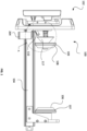
Figure 1 shows a side view of an adhesive roll mounting apparatus according to an aspect of the invention with the moveable core plug in its resting position and the latch in the latching position protruding from the drawer of the apparatus; -
Figure 2 shows a side view of the adhesive roll mounting apparatus according to the invention with the moveable core plug in an operating position and an adhesive roll mounted thereon; -
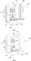
Figure 3 shows an enlarged view of the moveable core plug in circle A of the apparatus ofFigure 1 in its resting position and the latch in its first, protruding position; -
Figure 4 shows an enlarged view of the moveable core plug in circle B of the apparatus ofFigure 2 in its biased position and the latch in its second, stowed position; -
Figure 5 shows an enlarged view of the moveable core plug during assembly of an adhesive roll in the adhesive roll mounting apparatus according to the invention (a) in a resting position, (b) in a biased position and (c) in an operating position; -
Figure 6 shows a perspective view of a contacting cleaning apparatus according to an aspect of the invention with a drawer including the adhesive roll mounting apparatus ofFigure 1 in an extended position; and -
Figure 7 shows a cross-sectional view of another contacting cleaning apparatus according to an aspect of the invention with a moveable core plug in a resting position. -
Figures 1 and2 show an adhesiveroll mounting apparatus 100 in adrawer 102. Thedrawer 102 can be mounted in a housing (202, seeFigure 6 ) of a contact cleaning system (200, seeFigure 6 ). Thedrawer 102 includes a pair of opposing drawer slides 104, along which thedrawer 102 can be retracted into thehousing 202 to a closed position and extended out of thehousing 202 to an open position. - As shown in
Figure 1 , theroll mounting apparatus 100 includes a fixedcore plug 106 and amoveable core plug 108. The fixedcore plug 106 is mounted at a first end of thedrawer 102 closest to thehousing 202 when thedrawer 102 mounted to thehousing 202 and in an open position. The fixedcore plug 106 remains in a fixed position relative to thedrawer 102. Themoveable core plug 108 is mounted at a second end of thedrawer 102, opposite the first end. Themoveable core plug 108 is moveable in a linear direction away from the fixedcore plug 106 in thedrawer 102. Themoveable core plug 108 can thus be moved away from the fixedcore plug 106 in order to receive an adhesive roll (210, seeFigure 2 ). - The fixed
core plug 106 andmoveable core plug 108 each have a frustoconical portion. The frustoconical portion is at an end facing the opposing fixedcore plug 106 ormoveable core plug 108. The frustoconical portion of each of the fixed and moveable core plugs 106, 108 can be received in a hollow end of an adhesive role core. An adhesive roll (not shown) can thus be mounted between the fixedcore plug 106 andmoveable core plug 108.Figure 2 shows anadhesive roll 210 mounted between the fixedcore plug 106 and themoveable core plug 108. - As shown in
Figures 5(a) to (c) , themoveable core plug 108 has three positions relative to the fixedcore plug 106, a resting position (seeFigure 5(a) ), a biased position (seeFigure 5(b) ) and an operating position (seeFigure 5(c) ). Themoveable core plug 108 is biased towards the resting position, for example by a spring (118, seeFigures 3 and 4 ). - In the resting position, as shown in
Figures 1 ,3 and5(a) , themoveable core plug 108 is the closest to the fixedcore plug 106. There is no adhesive roll between themoveable core plug 108 and the fixedcore plug 106. In the biased position, as shown inFigure 5(b) , themoveable core plug 108 is furthest away from the fixedcore plug 106. The distance between themoveable core plug 108 and the fixedcore plug 106 is greater than the length of anadhesive roll 210, allowing anadhesive roll 210 to be positioned between the fixed andmoveable core plug moveable core plug Figures 2 ,4 and5(c) , themoveable core plug 108 is intermediate the resting and biased positions. Themoveable core plug 108 and the fixedcore plug 106 are each located in their respective hollow ends of the adhesive roll core and are spaced at a distance which allows rotation of theadhesive roll 210 about its longitudinal axis without any translation of the axis of rotation. - The fixed and moveable core plugs 106, 108 each include a
gripping element gripping element - As shown in
Figures 1 and2 , alatch 110 is pivotally mounted at the second end of thedrawer 102. Thelatch 110 is mounted on thedrawer 102 by a pin, or by another means which provides a fulcrum about which the latch can pivot. Thelatch 110, which is shown in an expanded view inFigures 3 and 4 , is formed of a body comprising afirst leg 112 and asecond leg 114 extending at an angle from one another in the same plane from a mutual pivot point (not shown). In the example shown, thesecond leg 114 extends at an angle approximately 90 degrees from thefirst leg 112. - The
moveable core plug 108 includes anactuator 117 fixedly connected to, and moveable with, the frustoconical portion of themoveable core plug 108. A surface of theactuator 117 is moveable into contact with thefirst leg 112 of thelatch 110. Theactuator 117 can press against thefirst leg 112 of thelatch 110 to actuate thelatch 110 to pivot. - The
actuator 117 moves into contact with thefirst leg 112 when themoveable core plug 108 is in the operating position, pivoting thefirst leg 112. -
Figures 1 and3 show thelatch 110 in a first pivotal, latching position and themoveable core plug 108 in the resting position. In this position, the surface of theactuator 117 is not in contact with thefirst leg 112 and thesecond leg 114 protrudes outwardly. In the first pivotal position, thesecond leg 114 of thelatch 110 abuts against a side of astopper element 204 of the housing (202, seeFigure 6 ), preventing thedrawer 102 from sliding from the open position to the closed position. This prevents thedrawer 102 from fully closing into thehousing 202 when thelatch 110 is in the latching position. In other words, thedrawer 102 may be partially, but not fully, received into thehousing 202 when thelatch 110 is in the latching position. - As shown particularly in
Figure 3 , themoveable core plug 108 is mounted to its mounting block by acore plug support 116 and aspring 118. Thecore plug support 116 is an elongate cylindrical member which passes through an aperture in themoveable core plug 108 as themoveable core plug 108 moves towards its mounting block. The sliding of thecore plug support 116 through the aperture in themoveable core plug 108 permits translational movement of the moveable core plug towards and away from itsmounting block 114. A retaining means is provided to retain themoveable core plug 108 on thecore plug support 116. The retaining means may be a fastener, for example a nut. - The
moveable core plug 108 is biased away from its mounting block by thespring 118. Thus, the translational movement of themoveable core plug 108 is against the bias of thespring 118. In use, thespring 118 will return themoveable core plug 108 towards the fixed core plug to hold an adhesive roll in place between themoveable core plug 108 and the fixedcore plug 106. - In examples, the
stopper element 204 may be a block, a lip, or other obstacle fixedly connected or integrally formed with thehousing 202. In other examples, thestopper element 204 may be a wall of thehousing 202. -
Figures 2 and4 show thelatch 110 in a second pivotal, disengaged position and themoveable core plug 108 is in the operating position. In this position, the surface of the actuator 117 acts on thefirst leg 112 and thesecond latch leg 114 is retracted. In the disengaged position, thelatch 110 is pivoted so as to retract thesecond leg 114 such that thesecond leg 114 no longer comes into contact with thestopper element 204, permitting thedrawer 102 to be slid between the open position and the closed position. Thus, thedrawer 102 can be fully received into thehousing 202. - The
latch 110 described herein is pivotable between the latching and disengaged positions. In alternative embodiments, thelatch 110 may be slidable, or otherwise moveable, between the latching and disengaged positions so as to prevent and/or permit thedrawer 102 to slide between open and closed positions. -
Figure 6 shows acontact cleaning system 200 including ahousing 202. Thedrawer 102, including the adhesiveroll mounting apparatus 100, is slidable into and out of thehousing 202 along the drawer slides 104. Eachdrawer slide 104 includes anouter member 105a, aninner member 105b. Theouter member 105a,inner member 105b are extendable in a telescopic manner. In one example, a fixed member is mounted to an internal surface of thehousing 202. Theouter member 105a is extendable along the fixed member, and theinner member 105b is extendable out of theouter member 105a in a direction parallel with the longitudinal axes of each of the outer andinner members drawer slide 104 may only include two members, an outer member mounted to thehousing 202 and an inner member extendable out of the outer member. - A
contact cleaning roller 220 is mounted in thehousing 202. Anadhesive roll 210 is mounted in the adhesiveroll mounting apparatus 100. The adhesiveroll mounting apparatus 100 containing theadhesive roll 210 is slidable into, and fully receivable within, thehousing 202 so that theadhesive roll 210 can be positioned in alignment with thecontact cleaning roller 220. During use of thecontact cleaning system 200, theadhesive roll 210 is positioned such that the surface of the adhesive roll is in contact with the surface of thecontact cleaning roller 220. - The
contact cleaning system 200 may include a sensor to detect whether the drawer is able to be fully received in thehousing 202. For example, the sensor may detect the position of thelatch 110 or the sensor may detect the position of thedrawer 102. When the sensor detects that thedrawer 102 is not able to be fully received in thehousing 202, for example thelatch 110 is in the latching position or thedrawer 102 is protruding from thehousing 202, the sensor can prevent thecontact cleaning apparatus 200 from being activated. When the sensor detects that thedrawer 102 can be fully received in thehousing 202, for example thelatch 110 is in the disengaged position or thedrawer 102 is fully received in thehousing 202, the sensor can enable thecontact cleaning apparatus 200 to be activated. The sensor may act as a switch to prevent or enable the activation of thecontact cleaning apparatus 200. Alternatively, the sensor may send the information to a controller of thecontact cleaning apparatus 200 which controls the activation of thecontact cleaning apparatus 200. - With reference to
Figures 1 to 6 , assembly of anadhesive roll 210 in thecontact cleaning apparatus 200 will now be described. An end of theadhesive roll 210 is placed against themoveable core plug 108. Theadhesive roll 210 can be used to move the moveable core plug 108 from the resting position (as shown inFigure 5(a) ) to the biased position (as shown inFigure 5(b) ). This allows the adhesive roll to be positioned between themoveable core plug 108 and the and the fixedcore 106 plug such that an opposing end of theadhesive roll 210 can receive the fixedcore plug 106 in the adhesive roll core. Themoveable core plug 108 is then moved to the operating position (as shown inFigure 5(c) ) to hold theadhesive roll 210 in place. This movement of themoveable core plug 108 pushes the surface of theactuator 117 against thefirst leg 112, causing thelatch 110 to pivot and thesecond latch leg 114 to be retracted away from thestopper element 204, as shown inFigure 4 . Theadhesive roll 210 is then retained between themoveable core plug 108 and the fixed core plug 106 (as shown inFigure 2 ), themoveable core plug 108 remains in the operating position and theactuator 117 holds thelatch 110 in the disengaged position. Thedrawer 102 is then slid to a closed position such that it is fully received into thehousing 202. With thedrawer 102 in the closed position, theadhesive roll 210 contacts thecontact cleaning roller 220 and thecontact cleaning system 200 can be operated. - During use of the
contact cleaning apparatus 200, a substrate is passed over thecontact cleaning roller 220 which rotates along the surface of the substrate and removes debris from the substrate. Theadhesive roll 210 is rotated by the rotation of thecontact cleaning roller 220 and collects the debris fromcontact cleaning roller 220. During operation of thecontact cleaning apparatus 200, an outer surface of theadhesive roll 210 can be replenished, either by adding an adhesive layer to theadhesive roll 210 or removing an adhesive layer from theadhesive roll 210. - When the
adhesive roll 210 is no longer usable, an operator will open thedrawer 102 and move themoveable core plug 108 to the biased position to remove the spentadhesive roll 210. Themoveable core plug 108 is then released and returns to the resting position by spring bias. As themoveable core plug 108 moves to the resting position, theactuator 117 releases thefirst leg 112 causing thelatch 110 to pivot back to the latching position and thesecond leg 114 to protrude, as shown inFigure 3 . If the operator tries to close thedrawer 102, thesecond leg 114 will foul on thestopper element 204 preventing thedrawer 102 from being fully received into thehousing 202. A freshadhesive roll 210 can then be replaced between themoveable core plug 108 and the fixedcore plug 106, as outlined above. - As shown in
Fig. 7 , there is shown another example of alatch 310 andmoveable core plug 308 according to the invention in a resting position. Where the features are the same as the example ofFig. 1 to Fig. 6 , the reference numbers are also kept the same, but with a "3" as the initial digit. - Similar to the embodiment shown in
Fig. 1 to Fig. 6 , alatch 310 is pivotally mounted at a second end of the drawer. Thelatch 310 is formed of a body comprising afirst leg 312 and asecond leg 314 extending at an angle from one another in the same plane from a mutual pivot point (not shown). In the example shown, thesecond leg 314 extends at an angle approximately 90 degrees from thefirst leg 312. - The
moveable core plug 308 includes anactuator 317 fixedly connected to, and moveable with, the frustoconical portion of themoveable core plug 308. Theactuator 317 is a flanged block. Theactuator 317 allows a user to pull back the spring-loaded section by hand, moving themoveable core plug 308 towards the mountingblock 314 to aid replacement of the adhesive roll. - A surface of the
actuator 317 is moveable into contact with thefirst leg 312 of thelatch 310. Theactuator 317 can press against thefirst leg 312 of thelatch 310 to actuate thelatch 310 to pivot. - The
actuator 317 moves into contact with thefirst leg 312 when themoveable core plug 308 is in the operating position, pivoting thefirst leg 312. - The
moveable core plug 308 includes agripping element 309. Thegripping element 309 is a cylindrical surface. The circumference of the cylindrical surface is configured to provide an interference fit with the adhesive roll core. Optionally, and the fixed core plug (not shown) also includes a corresponding gripping element. - The moveable core plug includes a stopping
element 319. The stoppingelement 319 is configured to abut the adhesive roll core and limit axial movement of the adhesive roll when it is in the loaded position. - All of the features disclosed in this specification (including any accompanying claims, abstract and drawings), and/or all of the steps of any method or process so disclosed, may be combined in any combination, except combinations where at least some of such features and/or steps are mutually exclusive.
- Each feature disclosed in this specification (including any accompanying claims, abstract and drawings), may be replaced by alternative features serving the same, equivalent or similar purpose, unless expressly stated otherwise. Thus, unless expressly stated otherwise, each feature disclosed is one example only of a generic series of equivalent or similar features.
- The invention is not restricted to the details of any foregoing embodiments. The invention extends to any novel one, or any novel combination, of the features disclosed in this specification (including any accompanying claims, abstract and drawings), or to any novel one, or any novel combination, of the steps of any method or process so disclosed. The claims should not be construed to cover merely the foregoing embodiments, but also any embodiments which fall within the scope of the claims.
-
- Adhesive
roll mounting apparatus 100 -
Drawer 102 - Drawer slides 104
-
Outer member 105a -
Inner member 105b - Fixed
core plug 106 -
Gripping element 107 -
Moveable core plug 108 -
Gripping element 109 -
Latch 110 -
First leg 112 -
Second leg 114 -
Core plug support 116 -
Actuator 117 -
Spring 118 -
Contact cleaning system 200 -
Housing 202 -
Stopper element 204 -
Adhesive roll 210 - Contact cleaning
roller 220 -
Drawer slide 304 -
Moveable core plug 308 -
Gripping element 309 -
Latch 310 -
First leg 312 -
Second leg 314 -
Core plug support 316 -
Actuator 317 -
Spring 318
Claims (13)
- A drawer for a contact cleaning system with a latching mechanism, the drawer comprising at least one drawer slide, a latch mounted on the drawer, and an actuator operable to move the latch between a latching position and a disengaged position.
- A drawer according to claim 1, wherein the latch is pivotable between the latching and disengaged positions.
- A drawer according to claim 1 or claim 2, wherein the latch is formed of a body comprising a first leg and a second leg, the first leg and the second leg extending at an angle from one another in the same plane from a mutual pivot point.
- A drawer according to claim 3, wherein the first leg is configured to be acted upon by the actuator causing the latch to pivot from the latching to the disengaged position.
- A drawer according to claim 3 or claim 4, wherein the second leg is configured to protrude outwardly so as to contact a stopper element of a housing of the contact cleaning system in the latching position and to be pivotable into the disengaged position wherein it is retracted so as to move out of contact with the stopper element.
- An adhesive roll mounting apparatus comprising a housing and a drawer receivable in the housing and being moveable into and out of the housing, the drawer comprising at least one drawer slide, a roll mounting system configured to receive and retain an adhesive roll, and a latch mounted on the drawer and moveable between a latching position in which the latch fouls against a stopper element of the housing preventing the drawer being received into the housing and a disengaged position in which the latch is held in a stowed position such that the drawer is received into the housing.
- An adhesive roll mounting apparatus according to claim 6, wherein the latch is pivotable between the latching and disengaged positions.
- An adhesive roll mounting apparatus according to claim 6 or claim 7, wherein the at least one drawer slide comprises a pair of opposing drawer slides.
- An adhesive roll mounting apparatus according to claim 8, wherein the roll mounting system comprises opposed core plugs mounted one at each end of the drawer.
- An adhesive roll mounting apparatus according to claim 8 or claim 9, wherein one of the opposing core plugs is fixed in position in the drawer and the other of the opposing core plugs is moveable away from the fixed core plug in the drawer.
- An adhesive roll mounting apparatus according to any one of claims 6 to 10, wherein the roll mounting system comprises an actuator operable to move the latch from the latching position to the disengaged position.
- An adhesive roll mounting apparatus according to claim 11 when dependent on claim 10, wherein the actuator is connected to the moveable core plug.
- A contact cleaning system comprising an adhesive roll mounting apparatus according to any one of claims 6 to 12 and a contact cleaning roller mounting apparatus mounted in the housing, wherein the contact cleaning roller mounting apparatus comprises a second drawer receivable in the housing and being moveable into and out of the housing, the second drawer comprising a roll mounting system configured to receive and retain a contact cleaning roller wherein the adhesive roll mounting apparatus and the contact cleaning roller mounting apparatus together provide a contact cleaning roller configured and located to contact a substrate to be cleaned and an adhesive roll configured and located to remove debris from the contact cleaning roller.
Priority Applications (3)
| Application Number | Priority Date | Filing Date | Title |
|---|---|---|---|
| KR1020240060659A KR20240164428A (en) | 2023-05-11 | 2024-05-08 | Contact cleaning apparatus |
| US18/661,169 US20240375156A1 (en) | 2023-05-11 | 2024-05-10 | Contact cleaning apparatus |
| JP2024076926A JP2024163093A (en) | 2023-05-11 | 2024-05-10 | Drawer, adhesive roll loading device, and contact cleaning system |
Applications Claiming Priority (1)
| Application Number | Priority Date | Filing Date | Title |
|---|---|---|---|
| GB2306955.2A GB2629816A (en) | 2023-05-11 | 2023-05-11 | Contact cleaning apparatus |
Publications (1)
| Publication Number | Publication Date |
|---|---|
| EP4461423A1 true EP4461423A1 (en) | 2024-11-13 |
Family
ID=86872306
Family Applications (1)
| Application Number | Title | Priority Date | Filing Date |
|---|---|---|---|
| EP24169537.8A Pending EP4461423A1 (en) | 2023-05-11 | 2024-04-10 | Contact cleaning apparatus |
Country Status (6)
| Country | Link |
|---|---|
| US (1) | US20240375156A1 (en) |
| EP (1) | EP4461423A1 (en) |
| JP (1) | JP2024163093A (en) |
| KR (1) | KR20240164428A (en) |
| CN (1) | CN118926205A (en) |
| GB (1) | GB2629816A (en) |
Citations (7)
| Publication number | Priority date | Publication date | Assignee | Title |
|---|---|---|---|---|
| US6237176B1 (en) * | 1998-09-08 | 2001-05-29 | Rayon Industrial Co., Ltd. | Substrate or sheet surface cleaning apparatus |
| WO2007010260A1 (en) * | 2005-07-20 | 2007-01-25 | Teknek Holdings Limited | Surface cleaning apparatus |
| US20090134639A1 (en) * | 2005-06-03 | 2009-05-28 | Dieter Ramsauer | Snap-action closure suitable for a thin-walled cabinet |
| GB2483242A (en) * | 2010-09-01 | 2012-03-07 | Itw Cs Uk Ltd | A contact cleaning apparatus |
| US8783177B2 (en) * | 2011-10-19 | 2014-07-22 | Brian Giardino | System for oscillating a roller |
| CN105880223A (en) * | 2016-07-14 | 2016-08-24 | 昆山东美自动化设备科技有限公司 | Flat plate cleaning machine |
| CN210647556U (en) * | 2019-08-01 | 2020-06-02 | 苏州市苏沁净化科技有限公司 | Special dust-sticking roller for dust-free workshop |
-
2023
- 2023-05-11 GB GB2306955.2A patent/GB2629816A/en active Pending
-
2024
- 2024-04-10 EP EP24169537.8A patent/EP4461423A1/en active Pending
- 2024-05-07 CN CN202410554438.8A patent/CN118926205A/en active Pending
- 2024-05-08 KR KR1020240060659A patent/KR20240164428A/en active Pending
- 2024-05-10 US US18/661,169 patent/US20240375156A1/en active Pending
- 2024-05-10 JP JP2024076926A patent/JP2024163093A/en active Pending
Patent Citations (7)
| Publication number | Priority date | Publication date | Assignee | Title |
|---|---|---|---|---|
| US6237176B1 (en) * | 1998-09-08 | 2001-05-29 | Rayon Industrial Co., Ltd. | Substrate or sheet surface cleaning apparatus |
| US20090134639A1 (en) * | 2005-06-03 | 2009-05-28 | Dieter Ramsauer | Snap-action closure suitable for a thin-walled cabinet |
| WO2007010260A1 (en) * | 2005-07-20 | 2007-01-25 | Teknek Holdings Limited | Surface cleaning apparatus |
| GB2483242A (en) * | 2010-09-01 | 2012-03-07 | Itw Cs Uk Ltd | A contact cleaning apparatus |
| US8783177B2 (en) * | 2011-10-19 | 2014-07-22 | Brian Giardino | System for oscillating a roller |
| CN105880223A (en) * | 2016-07-14 | 2016-08-24 | 昆山东美自动化设备科技有限公司 | Flat plate cleaning machine |
| CN210647556U (en) * | 2019-08-01 | 2020-06-02 | 苏州市苏沁净化科技有限公司 | Special dust-sticking roller for dust-free workshop |
Also Published As
| Publication number | Publication date |
|---|---|
| GB2629816A (en) | 2024-11-13 |
| KR20240164428A (en) | 2024-11-19 |
| GB202306955D0 (en) | 2023-06-28 |
| CN118926205A (en) | 2024-11-12 |
| JP2024163093A (en) | 2024-11-21 |
| US20240375156A1 (en) | 2024-11-14 |
Similar Documents
| Publication | Publication Date | Title |
|---|---|---|
| CN112207860B (en) | Single action convertible art knife and scraper | |
| US4749242A (en) | Drawer slide | |
| US8826483B2 (en) | Feed control lock for hand operated drain cleaner | |
| US11879276B2 (en) | Door handle device for vehicle | |
| EP0421275A1 (en) | Over and under telescoping slide assembly | |
| US20140208542A1 (en) | Breakaway hinge receptacle | |
| CN104936852A (en) | Stowable tailgate handle assembly | |
| US12305432B2 (en) | Door handle assembly for vehicle | |
| US20240375156A1 (en) | Contact cleaning apparatus | |
| CA2235666A1 (en) | Sliding gate valve for a vessel containing molten metal | |
| CA2535924A1 (en) | Multiple-bit driver with spring-loaded actuation | |
| KR100592099B1 (en) | Extension pipe support device and vacuum cleaner having the same | |
| CN111002332A (en) | Manipulator and transferring mechanical arm capable of automatically grabbing reaction cup | |
| JP2002029304A (en) | Vehicular article holding device | |
| US20240375157A1 (en) | Adhesive roll mounting system for contact cleaning apparatus | |
| US6660951B2 (en) | Canceling structure of combination switch | |
| JPH0552500U (en) | Leg opening adjustment device on tripod | |
| JP7284071B2 (en) | Combined structure of wiper blade and wiper arm | |
| US11117211B2 (en) | Spot welding electrode housing apparatus | |
| CN222367790U (en) | Auxiliary workbench and anesthesia machine | |
| CN223579491U (en) | Quick detach subassembly, photographic accessory and dismouting external member | |
| EP3447219A1 (en) | A locking mechanism | |
| CN222627646U (en) | Pull-out aid | |
| JP3495469B2 (en) | Extension tube for vacuum cleaner | |
| JPH08309679A (en) | Handle connecting structure for hold cutting tool or the like |
Legal Events
| Date | Code | Title | Description |
|---|---|---|---|
| PUAI | Public reference made under article 153(3) epc to a published international application that has entered the european phase |
Free format text: ORIGINAL CODE: 0009012 |
|
| STAA | Information on the status of an ep patent application or granted ep patent |
Free format text: STATUS: THE APPLICATION HAS BEEN PUBLISHED |
|
| AK | Designated contracting states |
Kind code of ref document: A1 Designated state(s): AL AT BE BG CH CY CZ DE DK EE ES FI FR GB GR HR HU IE IS IT LI LT LU LV MC ME MK MT NL NO PL PT RO RS SE SI SK SM TR |
|
| STAA | Information on the status of an ep patent application or granted ep patent |
Free format text: STATUS: REQUEST FOR EXAMINATION WAS MADE |
|
| 17P | Request for examination filed |
Effective date: 20250509 |