EP4461325A1 - Medical liquid detection sheet - Google Patents
Medical liquid detection sheet Download PDFInfo
- Publication number
- EP4461325A1 EP4461325A1 EP23737310.5A EP23737310A EP4461325A1 EP 4461325 A1 EP4461325 A1 EP 4461325A1 EP 23737310 A EP23737310 A EP 23737310A EP 4461325 A1 EP4461325 A1 EP 4461325A1
- Authority
- EP
- European Patent Office
- Prior art keywords
- detection
- liquid
- wiring
- sheet
- base member
- Prior art date
- Legal status (The legal status is an assumption and is not a legal conclusion. Google has not performed a legal analysis and makes no representation as to the accuracy of the status listed.)
- Pending
Links
Images



Classifications
-
- A—HUMAN NECESSITIES
- A61—MEDICAL OR VETERINARY SCIENCE; HYGIENE
- A61M—DEVICES FOR INTRODUCING MEDIA INTO, OR ONTO, THE BODY; DEVICES FOR TRANSDUCING BODY MEDIA OR FOR TAKING MEDIA FROM THE BODY; DEVICES FOR PRODUCING OR ENDING SLEEP OR STUPOR
- A61M1/00—Suction or pumping devices for medical purposes; Devices for carrying-off, for treatment of, or for carrying-over, body-liquids; Drainage systems
- A61M1/36—Other treatment of blood in a by-pass of the natural circulatory system, e.g. temperature adaptation, irradiation ; Extra-corporeal blood circuits
- A61M1/3621—Extra-corporeal blood circuits
- A61M1/3653—Interfaces between patient blood circulation and extra-corporal blood circuit
- A61M1/3656—Monitoring patency or flow at connection sites; Detecting disconnections
-
- A—HUMAN NECESSITIES
- A61—MEDICAL OR VETERINARY SCIENCE; HYGIENE
- A61F—FILTERS IMPLANTABLE INTO BLOOD VESSELS; PROSTHESES; DEVICES PROVIDING PATENCY TO, OR PREVENTING COLLAPSING OF, TUBULAR STRUCTURES OF THE BODY, e.g. STENTS; ORTHOPAEDIC, NURSING OR CONTRACEPTIVE DEVICES; FOMENTATION; TREATMENT OR PROTECTION OF EYES OR EARS; BANDAGES, DRESSINGS OR ABSORBENT PADS; FIRST-AID KITS
- A61F13/00—Bandages or dressings; Absorbent pads
- A61F13/00051—Accessories for dressings
-
- A—HUMAN NECESSITIES
- A61—MEDICAL OR VETERINARY SCIENCE; HYGIENE
- A61B—DIAGNOSIS; SURGERY; IDENTIFICATION
- A61B2562/00—Details of sensors; Constructional details of sensor housings or probes; Accessories for sensors
- A61B2562/02—Details of sensors specially adapted for in-vivo measurements
- A61B2562/029—Humidity sensors
-
- A—HUMAN NECESSITIES
- A61—MEDICAL OR VETERINARY SCIENCE; HYGIENE
- A61M—DEVICES FOR INTRODUCING MEDIA INTO, OR ONTO, THE BODY; DEVICES FOR TRANSDUCING BODY MEDIA OR FOR TAKING MEDIA FROM THE BODY; DEVICES FOR PRODUCING OR ENDING SLEEP OR STUPOR
- A61M2205/00—General characteristics of the apparatus
- A61M2205/33—Controlling, regulating or measuring
- A61M2205/3317—Electromagnetic, inductive or dielectric measuring means
Definitions
- This invention relates to a liquid detection sheet for medical use, which is used to detect blood leakage, etc. in the medical field.
- Patent Document 1 Japanese Unexamined Patent Publication No. JP-A-2012-196293
- Patent Document 1 Japanese Unexamined Patent Publication No. JP-A-2012-196293
- Patent Document 1 JP-A-2012-196293
- perspiration, etc. of a patient may be mistakenly detected as the occurrence of liquid leakage, and there is a need to avoid false detection of liquids that do not need to be detected, such as perspiration, while effectively detecting detection target liquids such as blood and liquid medicine.
- Patent Document 1 since the sheet that constitutes the liquid detection region has a six-layer structure, the number of parts is large and the manufacturing is time-consuming.
- an external circuit is generally connected to the two detection wirings via a detachable connector, but there is a risk that the connector may not be properly connected electrically due to such factors as being connected at an angle.
- the connector is often subjected to external force, there is a risk of misalignment of the connector or disconnection in the wiring of the connector.
- each preferred embodiment described below is exemplary and can be appropriately combined with each other.
- a plurality of elements described in each preferred embodiment can be recognized and adopted as independently as possible, or can also be appropriately combined with any element described in other preferred embodiments.
- various other preferred embodiments can be realized without being limited to those described below.
- a first preferred embodiment provides a liquid detection sheet for medical use comprising: a base member having electric insulation properties; and a first detection wiring and a second detection wiring provided remote from each other on the base member, the liquid detection sheet being configured to detect leakage of a detection target liquid such as blood based on a change in an electrical connection state between the first detection wiring and the second detection wiring due to sticking of the detection target liquid, wherein a main detection region in which the first detection wiring and the second detection wiring extend substantially parallel to each other is provided on the base member, and a distance between the first detection wiring and the second detection wiring opposed to each other in the main detection region is set within a range of 40 to 100 mm.
- the distance between the first detection wiring and the second detection wiring opposed to each other in the main detection region is set within the range of 40 to 100 mm.
- a second preferred embodiment provides a liquid detection sheet for medical use comprising: a base member having electric insulation properties; and a plurality of detection wirings provided remote from each other on the base member, the liquid detection sheet being configured to detect leakage of a detection target liquid such as blood based on a change in an electrical connection state between the plurality of detection wirings due to sticking of the detection target liquid, wherein an upper surface of the base member on which the plurality of detection wirings are formed by printing is covered with nonwoven fabric, and the base member and the nonwoven fabric are adhered to each other by a heat-welding sheet.
- the detection wirings are formed by printing on the base member, so that the liquid detection sheet has a three-layer structure with a small number of layers, thereby facilitating manufacturing, reducing costs, and the like.
- the detection target liquid is absorbed by the nonwoven fabric and spreads out, thereby inhibiting the detection target liquid from spilling or sticking to the patient.
- the base member and the nonwoven fabric laminated can be adhered to each other without requiring an adhesive application process.
- a third preferred embodiment provides a liquid detection sheet for medical use comprising: a base member having electric insulation properties; and a plurality of detection wirings provided remote from each other on the base member, the liquid detection sheet being configured to detect leakage of a detection target liquid such as blood based on a change in an electrical connection state between the plurality of detection wirings due to sticking of the detection target liquid, wherein a liquid-impermeable member that prevents passage of the detection target liquid is arranged below the plurality of detection wirings.
- the detection target liquid it is difficult for the detection target liquid to pass through the liquid-impermeable member and leak downward, thereby detecting the detection target liquid that accumulates on the liquid-impermeable member with excellent reliability.
- the detection target liquid by keeping the detection target liquid on the liquid-impermeable member, contamination of the bed due to sticking of the detection target liquid will be avoided, for example, when the liquid detection sheet is laid on the bed.
- a fourth preferred embodiment provides the liquid detection sheet for medical use according to the third preferred embodiment, wherein terminals of the plurality of detection wirings are located at a widthwise center portion of the base member in an outer peripheral end of the base member.
- the liquid detection sheet including the liquid-impermeable member cannot be used by being turned upside down.
- the terminals of the detection wirings which are located at the outer peripheral end of the base member, are arranged biasedly in the width direction of the base member, the distance from the terminals of the detection wirings to the external device will change between the case where the liquid detection sheet is used by being laid below the left arm of the patient and the case where the liquid detection sheet is used by being laid below the right arm of the patient, thereby causing differences in the required length and handling of the external wiring connected to the terminals of the detection wirings.
- the terminals of the detection wirings are located at the widthwise center portion of the base member.
- the difference in the handling of the external wiring is minimized between the case where the liquid detection sheet is used on the left side of the patient and the case where the liquid detection sheet is used on the right side of the patient, for example, and in both cases, the external wiring is less likely to become an obstacle.
- a fifth preferred embodiment provides a liquid detection sheet for medical use comprising: a base member having electric insulation properties; and a first detection wiring and a second detection wiring provided remote from each other on the base member, the liquid detection sheet being configured to detect leakage of a detection target liquid such as blood based on a change in an electrical connection state between the first detection wiring and the second detection wiring due to sticking of the detection target liquid, wherein the second detection wiring is provided so as to surround the first detection wiring on the base member.
- the liquid detection sheet for medical use structured following the present preferred embodiment, by connecting a check circuit to the two ends of the second detection wiring, the electrical state of the second detection wiring (disconnection, etc.) can be checked by applying a small check voltage. Besides, since the first detection wiring has a specific wiring mode with respect to the second detection wiring, the normal condition of the first detection wiring can be estimated by checking the second detection wiring.
- the first detection wiring and the second detection wiring which detect the liquid by means of a change in the electrical connection state therebetween, are configured such that the second detection wiring surrounds the first detection wiring relatively nearby.
- bending of the first detection wiring is accompanied by bending of the second detection wiring, and disconnection due to bending of the first detection wiring alone is difficult to assume. Therefore, if the first detection wiring is disconnected due to bending of the base member, for example, the second detection wiring surrounding the first detection wiring will also be disconnected. Accordingly, the electrical state of the first detection wiring can be estimated by checking the electrical state of the second detection wiring.
- the electrical abnormalities such as disconnection of the first detection wiring can be checked based on the electrical state of the second detection wiring, thereby making it easier to check the first and second detection wirings.
- a sixth preferred embodiment provides the liquid detection sheet for medical use according to the fifth preferred embodiment, wherein the first detection wiring and the second detection wiring are each imparted with a comb teeth-like shape by opposite wiring parts extending substantially parallel to each other and a plurality of branched wiring parts extending from the respective opposite wiring parts in a direction of opposition of the opposite wiring parts, and the plurality of branched wiring parts of the first detection wiring and the plurality of branched wiring parts of the second detection wiring are arranged in a length direction of the opposite wiring parts so as to interdigitate with one another in the direction of opposition of the opposite wiring parts.
- the liquid detection sheet for medical use structured following the present preferred embodiment it is possible to prevent the spacing between the first detection wiring and the second detection wiring from becoming too large, thereby detecting the detection target liquid with high accuracy.
- the branched wiring parts interdigitate with one another in the direction of opposition of the opposite wiring parts, and the branched wiring parts are arranged in the length direction of the opposite wiring parts. This makes it possible to efficiently obtain a relatively large effective detection area.
- a seventh preferred embodiment provides the liquid detection sheet for medical use according to the fifth or sixth preferred embodiment, wherein a first terminal is provided at one end portion of the first detection wiring, a pair of second terminals are provided at two end portions of the second detection wiring, and the first terminal and the pair of second terminals are arranged side by side in a straight line, and the first terminal is located between the pair of second terminals.
- the first terminal provided at one end portion of the first detection wiring and the pair of second terminals provided at the two end portions of the second detection wiring are arranged side by side in a straight line, which facilitates connection of the detection circuit to the first terminal and the second terminals.
- the arrangement of the first terminal between the pair of second terminals makes it easier to arrange the second detection wiring so as to surround the first detection wiring.
- An eighth preferred embodiment provides the liquid detection sheet for medical use according to any one of the fifth through seventh preferred embodiments, wherein the base member comprises a base sheet that is impermeable to the detection target liquid, the first detection wiring and the second detection wiring are formed by printing on an upper surface of the base sheet, and a liquid-permeable sheet that has electric insulation properties and allows passage of the detection target liquid is provided on the upper surface of the base sheet so as to cover the first detection wiring and the second detection wiring.
- the detection target liquid accumulates on the base sheet because the base sheet is impermeable to the detection target liquid. Therefore, the amount of the detection target liquid on the base sheet gradually increases and the area of the detection target liquid on the base sheet becomes larger, which increases the possibility of the detection target liquid touching both the first detection wiring and the second detection wiring to be detected.
- the base sheet which does not require liquid-permeable properties, can easily be made smooth, and by the first and second detection wirings being formed by printing on the base sheet, disconnection or the like of the first and second detection wirings due to printing defects is unlikely to occur.
- the liquid-permeable sheet having liquid-permeable properties is overlapped on the base sheet, and the liquid-permeable sheet diffusely transmits the detection target liquid sticking from above. This facilitates conduction by the detection target liquid between the first and second detection wirings, thereby increasing the reliability of detection. Furthermore, since the flow of the detection target liquid on the base sheet is limited by the liquid-permeable sheet, the detection target liquid is unlikely to spill out of the base sheet and is easier to detect by accumulating on the base sheet, while avoiding contamination of the surrounding area by the detection target liquid. Additionally, the liquid-permeable sheet covering the first and second detection wirings formed by printing on the base sheet has electric insulation properties. Thus, even if the body of the patient comes into contact with the liquid-permeable sheet, for example, the body of the patient will not cause conduction between the first and second detection wirings, thereby preventing false detection.
- a ninth preferred embodiment provides the liquid detection sheet for medical use according to any one of the fifth through eighth preferred embodiments, further comprising a state checking member connected to the two end portions of the second detection wiring and configured to check an electrical state of the second detection wiring by applying a check voltage to the second detection wiring.
- the state checking member is connected to the two end portions of the second detection wiring, thereby checking the electrical state of the second detection wiring with a relatively small check voltage.
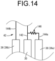
- a tenth preferred embodiment provides a liquid detection sheet for medical use comprising: a base member having electric insulation properties; and a plurality of detection wirings provided remote from each other on the base member, the liquid detection sheet being configured to detect leakage of a detection target liquid such as blood based on a change in an electrical connection state between the plurality of detection wirings due to sticking of the detection target liquid, wherein the plurality of detection wirings are connected to each other by a resistor at a position outside a main detection region configured to detect the leakage of the detection target liquid.
- liquid detection sheet for medical use structured following the present preferred embodiment based on differences in energization resistance, checking for disconnection of the detection wirings and detection of the liquid can be performed by the same application mode of voltage.
- the resistor can be provided in the internal circuit of a connector connected to the liquid detection sheet, which provides a greater degree of freedom in selecting a resistor compared to the case where the resistor is provided in the main detection region of the liquid detection sheet.
- the resistor can be provided at a position outside the main detection region with which the detection target liquid comes into contact, the detection target liquid can be prevented from touching the resistor.
- An eleventh preferred embodiment provides a liquid detection sheet for medical use comprising: a base member having electric insulation properties; and a first detection wiring and a second detection wiring provided remote from each other on the base member, the liquid detection sheet being configured to detect leakage of a detection target liquid such as blood based on a change in an electrical connection state between the first detection wiring and the second detection wiring due to sticking of the detection target liquid, wherein one of the first detection wiring and the second detection wiring includes a curved part spaced outward from an end of the other of the first detection wiring and the second detection wiring and extending in an arc-like shape.
- the change in the remote distance between the aforementioned one detection wiring and the other of the first and second detection wirings is reduced, and the change in the amount of the detection target liquid that is detectable in the length direction of the one detection wiring can be minimized, thereby achieving highly reliable liquid detection.
- a twelfth preferred embodiment provides a liquid detection sheet for medical use comprising: a base member having electric insulation properties; and a plurality of detection wirings provided remote from each other on the base member, the liquid detection sheet being configured to detect leakage of a detection target liquid such as blood based on a change in an electrical connection state between the plurality of detection wirings due to sticking of the detection target liquid, wherein terminals of the plurality of detection wirings are arranged side by side in an outer peripheral portion of the base member, and positioning parts are provided to the base member on opposite sides in a direction of arrangement of the terminals and located close to the terminals, the positioning parts positioning a connector with respect to the base member, the connector including an external wiring electrically connected to the terminals.
- the base member and the connector are positioned by the positioning parts at the locations close to the pair of terminals located at the two ends in the direction of arrangement of the terminals, so that the connector is properly positioned with respect to the pair of terminals at the two ends.
- the proper positioning of the connector with respect to the pair of terminals at the two ends also ensures that the connector is properly positioned with respect to the intermediate terminal located between the pair of terminals at the two ends. This makes it possible to stably connect the internal circuit of the connector with respect to all of the plurality of terminals.
- a thirteenth preferred embodiment provides the liquid detection sheet for medical use according to the twelfth preferred embodiment, wherein the base member comprises a base sheet that is impermeable to the detection target liquid, and the base sheet is provided with a positioning hole through which a positioning pin protruding from the connector is inserted, and the positioning parts include the positioning hole.
- a proper connection between the plurality of terminals provided on the base sheet and the internal circuit of the connector is easily achieved by a simple structure in which the positioning pin on the connector side is inserted through the positioning hole of the base sheet.
- the positioning hole is easy to form and the positioning action is effectively achieved.
- a fourteenth preferred embodiment provides the liquid detection sheet for medical use according to the thirteenth preferred embodiment, wherein an annular reinforcing part is provided at a periphery of an opening of the positioning hole of the base sheet, the annular reinforcing part protruding in a thickness direction of the base sheet.
- the positioning pin when the positioning pin is pressed against the inner circumferential surface of the positioning hole by the action of external force, damage such as tearing of the base sheet is prevented by the reinforcing part.
- the length of the positioning hole provided to the thin-walled base sheet is increased by the reinforcing part, the contact area between the positioning pin and the positioning hole is enlarged, which makes it possible to obtain the positioning action more advantageously and to expect improved durability due to dispersion of stress.
- a fifteenth preferred embodiment provides a liquid detection sheet for medical use comprising: a base member having electric insulation properties; and a plurality of detection wirings provided remote from each other on the base member, the liquid detection sheet being configured to detect leakage of a detection target liquid such as blood based on a change in an electrical connection state between the plurality of detection wirings due to sticking of the detection target liquid, wherein a connector including an internal circuit electrically connected to terminals of the plurality of detection wirings is provided, and an external wiring electrically connected to the internal circuit of the connector and extending to an outside from the connector is configured such that the external wiring extends from the internal circuit to a side on which the connector is connected to the terminals, and an extending end of the external wiring curves so as to make a U-turn and extends to the outside from the connector on a side opposite to the side on which the connector is connected to the terminals.
- the external wiring extends from the internal circuit to the side on which the connector is connected to the terminals and the extending end of the external wiring curves so as to make a U-turn.
- the external wiring is pulled by the action of external force, damage to the external wiring itself or to the connected portion between the external wiring and the internal circuit or the like is prevented owing to deformation of the curved portion.
- a sixteenth preferred embodiment provides a liquid detection sheet for medical use comprising: a base member having electric insulation properties; and a plurality of detection wirings provided remote from each other on the base member, the liquid detection sheet being configured to detect leakage of a detection target liquid such as blood based on a change in an electrical connection state between the plurality of detection wirings due to sticking of the detection target liquid, wherein a connector including an internal circuit electrically connected to terminals of the plurality of detection wirings is provided, a distal end portion of the connector includes an upper jaw part and a lower jaw part that are relatively displaceable in a direction of mutual separation and in a direction of mutual approach, an external wiring is electrically connected to the terminals via the internal circuit of the connector by an outer peripheral portion of the base member being clasped between the upper jaw part and the lower jaw part in a vertical direction, and the lower jaw part of the connector arranged below the base member is configured such that an upper surface comprises a sloping surface that slopes downward toward a distal end of the connector attached to the base member
- the lower jaw part becomes thinner in the vertical direction toward the distal end of the connector attached to the base member. This makes it easy to insert the lower jaw part of the connector into the under part of the base member placed on the bed, thereby facilitating connection operation of the connector to the base member placed on the bed.
- a seventeenth preferred embodiment provides the liquid detection sheet for medical use according to the sixteenth preferred embodiment, wherein the connector includes an urging member that urges distal end portions of the upper jaw part and the lower jaw part attached to the base member in the direction of mutual approach.
- the upper jaw part and the lower jaw part are urged in the direction of mutual approach by the urging member.
- the connector can be easily attached to the base member by clasping the base member between the upper and lower jaw parts by means of urging force of the urging member.
- the connector since the connector is maintained in the attached state to the base member by the urging force exerted on the upper and lower jaw parts by the urging member, no special locking operation or the like is required.
- the detection target liquid can be detected with high accuracy while suppressing false detection of, for example, perspiration of a patient or the like that does not require detection.
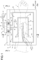
- FIGS. 1 to 3 show a liquid detection device 12 including a liquid detection sheet 10 for medical use according to a first practical embodiment of the present invention.
- the liquid detection device 12 has a structure in which a connector 14 is attached to the liquid detection sheet 10.
- the vertical direction refers to the vertical direction in FIG. 3 , which is the vertical direction in the state of use
- the front-back direction refers to the vertical direction in FIG. 1
- the left-right direction refers to the left-right direction in FIG. 1 .
- the thickness of the components, the width of the detection wirings, and the like are exaggerated for illustrative purposes.
- the liquid detection sheet 10 has a laminated structure in which a base sheet 16 serving as a base member and a liquid-permeable sheet 18 overlapped on the upper surface of the base sheet 16 are fastened to each other by an adhesive sheet 20.
- the base sheet 16 is in the form of a thin-walled sheet or film.
- the base sheet 16 is a liquid-impermeable member having liquid-impermeable properties that is not permeable to liquids such as blood.
- the base sheet 16 is made of an electrically insulating material.
- the base sheet 16 is made of a synthetic resin material, for example, and specifically, can be made of polyethylene terephthalate (PET). It is desirable that the thickness of the base sheet 16 be 0.01 mm to 0.5 mm from the viewpoint of, for example, minimizing sense of discomfort (stiffness) when a patient places his/her arm or the like on the liquid detection sheet 10 while ensuring the necessary electric insulation properties, and in this practical embodiment, the thickness is 0.05 mm, for example.
- a first detection wiring 22 and a second detection wiring 24 are provided on the base sheet 16. Both the first detection wiring 22 and the second detection wiring 24 are made of a conductive material, for example, a conductive paste made of a synthetic resin material mixed with a conductive filler made of a conductive material such as metal and carbon.
- the first detection wiring 22 and the second detection wiring 24 made of a conductive paste are each formed by printing in a predetermined shape (pattern) on the upper surface of the base sheet 16. Accordingly, the liquid-impermeable base sheet 16 is arranged below the first detection wiring 22 and the second detection wiring 24.
- the first detection wiring 22 includes a first central detection part 26 having a laterally rotated U shape with the left side open at the center portion of the base sheet 16, and also includes a terminal connecting part 28 extending straightly from the first central detection part 26 toward the back of the base sheet 16.
- a first terminal 30 that is located at the back end of the base sheet 16 and is electrically connected to the connector 14 described below.
- the second detection wiring 24 is arranged remote from the first detection wiring 22 and is provided so as to surround the first detection wiring 22. That is, the second detection wiring 24 includes an outer circumferential detection part 32 surrounding the first central detection part 26 of the first detection wiring 22, and also includes a second central detection part 34 extending from the outer circumferential detection part 32 so as to be inserted into the left side opening of the first central detection part 26 of the first detection wiring 22.
- the outer circumferential detection part 32 of the second detection wiring 24 is arranged such that its two end portions are disposed remote from each other on the left-right opposite sides of the terminal connecting part 28 of the first detection wiring 22 and are located at the back end of the base sheet 16.
- a pair of second terminals 36, 36 are provided at the two end portions of the outer circumferential detection part 32 of the second detection wiring 24.
- the pair of second terminals 36, 36 are disposed remote from each other on the left-right opposite sides of the first terminal 30, and those first terminal 30 and second terminals 36, 36 are arranged side by side in a straight line in the left-right direction.
- the direction of arrangement of the first terminal 30 and the second terminals 36, 36 is the left-right direction.
- the first terminal 30 and the second terminals 36, 36 are suitably provided at the center portion of the base sheet 16 in the left-right width direction, and more suitably, they are provided approximately lineally symmetrically with respect to the left-right center line of the base sheet 16.
- the connector 14 to be positioned at the center portion of the base sheet 16 in the left-right direction, with the connector 14 positioned on the opposite side (outside) of the body of a patient (1), regardless of whether the liquid detection sheet 10 is used on the right or left forearm (5) of the patient (1) in the state of use described below.
- the distance from the connector 14 to a detector (52), which is described below, does not change significantly, making it easier to avoid excessive or insufficient wiring length.
- a left end 32a of the outer circumferential detection part 32 in the second detection wiring 24 extends in the front-back direction, and is approximately parallel to a right end 26a of the first central detection part 26 in the first detection wiring 22, which extends in the front-back direction, so as to be opposite to each other in the left-right direction.
- the right end 26a extending in the front-back direction in the first central detection part 26 and the left end 32a extending in the front-back direction in the outer circumferential detection part 32 serve as opposite wiring parts of this practical embodiment.
- the first central detection part 26 includes front and back ends 26b, 26c extending leftward from the right end 26a.
- the first detection wiring 22 and the second detection wiring 24 include branched wiring parts 26b, 26c, 32b, 32c, 34 extending straightly from the respective opposite wiring parts 26a, 32a in the direction of opposition of those opposite wiring parts 26a, 32a.
- the first detection wiring 22 and the second detection wiring 24 are each imparted with an approximately comb-teeth shape in the portions constituted by the opposite wiring parts 26a, 32a and the branched wiring parts 26b, 26c, 32b, 32c, 34.
- the branched wiring parts 26b, 26c of the first detection wiring 22 and the branched wiring parts 32b, 32c, 34 of the second detection wiring 24 are arranged alternately at approximately regular intervals in the front-back direction so as to interdigitate with one another in the left-right direction.
- the right end 26a in the first central detection part 26 of the first detection wiring 22 and the left end 32a in the outer circumferential detection part 32 of the second detection wiring 24 extend parallel to each other, while the front and back ends 26b, 26c in the first central detection part 26 and the front and back ends 32b, 32c and the second central detection part 34 of the second detection wiring 24 extend parallel to one another. Accordingly, those portions in the first and second detection wirings 22, 24 that extend parallel to and are opposite to one another constitute a main detection region 37 of this practical embodiment.
- the main detection region 37 of this practical embodiment is set to the radially inner portion of the liquid detection sheet 10 surrounded by the outer circumferential detection part 32 of the second detection wiring 24.
- the right end 26a of the first central detection part 26 and the right end 32d of the outer circumferential detection part 32 are mutually remote and extend in parallel, and the remote distance therebetween is approximately the same as the remote distance D between the front and back ends 26b, 26c of the first central detection part 26 and the front and back ends 32b, 32c of the outer circumferential detection part 32 as well as the second central detection part 34.
- the right end 26a of the first central detection part 26 and the right end 32d of the outer circumferential detection part 32 also constitute the main detection region 37.
- the first detection wiring 22 and the second detection wiring 24 are remote from each other on the base sheet 16, and the distance D between the first central detection part 26 of the first detection wiring 22 and the outer circumferential detection part 32 as well as the second central detection part 34 of the second detection wiring 24 opposed to each other (the distance of opposition in the main detection region 37) is set within the range of 40 mm to 100 mm.
- the first central detection part 26 of the first detection wiring 22, and the outer circumferential detection part 32 as well as the second central detection part 34 of the second detection wiring 24 both have a configuration constituted by combination of a plurality of straight portions (the right end 26a, the front end 26b, and the back end 26c in the first detection wiring 22, and the left end 32a, the front end 32b, and the back end 32c, the right end 32d, and the second central detection part 34 in the second detection wiring 24).
- the distance D between the first central detection part 26 of the first detection wiring 22 and the outer circumferential detection part 32 as well as the second central detection part 34 of the second detection wiring 24 opposed to each other refers to the distance between the straight portions of the first central detection part 26, the outer circumferential detection part 32 and the second central detection part 34 that extend approximately parallel to one another.
- the distance D between the straight portions of the first central detection part 26, the outer circumferential detection part 32 and the second central detection part 34 is approximately constant.
- the distance between the straight portions of the first central detection part 26, the outer circumferential detection part 32 and the second central detection part 34 may be different for each straight portion, in which case the minimum distance between the straight portions is 40 mm or more and the maximum distance between the straight portions is 100 mm or less.
- the back end of the base sheet 16 is provided with a pair of positioning holes 38, 38 serving as a positioning part.
- the positioning holes 38 perforate the base sheet 16 in the thickness direction, and have, for example, a circular cross-section.
- the pair of positioning holes 38, 38 are arranged remote from each other in the left-right direction, and are located on the left-right opposite outer sides of the pair of second terminals 36, 36.
- the positioning hole 38 is arranged close to the second terminal 36 in the left-right direction.
- the distance between the positioning hole 38 and the second terminal 36 arranged adjacently is 30 mm or less, more suitably 15 mm or less.
- An annular reinforcing part 40 is provided at the periphery of the opening of each positioning hole 38.
- the reinforcing part 40 is provided at the periphery of the opening of the positioning hole 38 so as to protrude outward in the thickness direction of the base sheet 16.
- the reinforcing part 40 is formed of, for example, synthetic resin or metal, and the deformation rigidity of the base sheet 16 is increased at the portion where the reinforcing part 40 is provided.
- the reinforcing part 40 may be formed integrally with the base sheet 16 or may be formed as a separate member from the base sheet 16 and fastened to the base sheet 16 by welding or other means. In this practical embodiment, the reinforcing parts 40 are provided at the peripheries of the openings on both the upper and lower sides of the positioning holes 38, but may be provided only at the periphery of the opening on either the upper or lower side, for example.
- the liquid-permeable sheet 18 has liquid-permeable properties to allow passage of a detection target liquid, such as blood, and is also has electric insulation properties.
- the liquid-permeable sheet 18 may be woven or knitted fabric, but is constituted by, for example, nonwoven fabric. As shown in FIG. 4 , the liquid-permeable sheet 18 is overlapped on the upper surface of the base sheet 16, and covers the first detection wiring 22 and the second detection wiring 24 provided on the upper surface of the base sheet 16.
- the liquid-permeable sheet 18 has approximately the same dimensions in the left-right direction and shorter dimensions in the front-back direction compared to the base sheet 16, and the back end portion of the base sheet 16 protrudes backward from the liquid-permeable sheet 18 to be exposed.
- the first terminal 30 and the second terminals 36, 36 are not covered by the liquid-permeable sheet 18, but are exposed to the outside behind the liquid-permeable sheet 18.
- the pair of positioning holes 38, 38 arranged on the left-right opposite outer sides of the second terminals 36, 36 are located behind the liquid-permeable sheet 18, and are formed only on the base sheet 16.
- the base sheet 16 and the liquid-permeable sheet 18 are coupled to each other by the adhesive sheet 20 serving as an adhesive layer.
- the adhesive sheet 20 is, for example, a synthetic resin sheet with glue layers on both sides. One glue layer is adhered to the base sheet 16 and the other glue layer is adhered to the liquid-permeable sheet 18, thereby holding the base sheet 16 and the liquid-permeable sheet 18 in an overlapped state.
- the adhesive sheet 20 has liquid-permeable properties to allow passage of the detection target liquid.
- the adhesive sheet 20 may be, for example, a heat-welding sheet.
- the heat-welding sheet is made of thermoplastic resin such as polyimide, polyester, or polyurethane, for example, and becomes adhesive upon heating and solidifies upon cooling.
- the base sheet 16 and the liquid-permeable sheet 18 can be adhered to each other by heating the heat-welding sheet and then cooling it, with the heat-welding sheet (the adhesive sheet 20) overlapped on the upper surface of the base sheet 16 and interposed between the base sheet 16 and the liquid-permeable sheet 18.
- the adhesive sheet 20 (the heat-welding sheet) is able to allow passage of the detection target liquid by, for example, being made in a mesh pattern, even if it is not made of a liquid-permeable material.
- the base sheet 16 and the liquid-permeable sheet 18 may be coupled to each other by an adhesive, for example, without using the adhesive sheet 20.
- the heat-welding sheet may be formed by thermosetting resin such as epoxy resin.
- the connector 14 is attached to the liquid detection sheet 10 having such a structure.
- the connector 14 includes an internal circuit 42 (see FIG. 3 ) which is connected to the first detection wiring 22 and the second detection wiring 24 of the liquid detection sheet 10, and includes an external wiring 44 which is electrically connected to the internal circuit 42 and extends to the outside.
- the internal circuit 42 of the connector 14 is connected via the external wiring 44 to a detector 52 outside (described later).
- the connector 14 is attached to the back end portion of the liquid detection sheet 10. That is, the connector 14 includes a lower jaw part 46 that is overlapped on the lower surface of the base sheet 16, and an upper jaw part 48 that is overlapped on the upper surface of the base sheet 16. The base sheet 16 is clasped between those lower jaw part 46 and upper jaw part 48.
- the lower jaw part 46 is provided with a pair of positioning pins 50, 50.
- the positioning pin 50 projects upward from the lower jaw part 46, and has a circular transverse cross section corresponding to the hole cross section of the positioning hole 38 in the base sheet 16.
- the positioning hole 38 of this practical embodiment has an approximately cylindrical shape which can be inserted through the positioning hole 38.
- the pair of positioning pins 50, 50 are provided remote from each other in the left-right direction. The remote distance between the pair of positioning pins 50, 50 in the left-right direction is larger than the left-right dimension of the portion of the upper jaw part 48 located between the pair of positioning pins 50, 50.
- the upper jaw part 48 is located between the pair of positioning pins 50, 50 when the connector 14 is attached to the base sheet 16.
- the positioning pins 50, 50 are inserted through the positioning holes 38, 38 of the base sheet 16. Accordingly, the connector 14 is positioned with respect to the base sheet 16 in the vertical direction by clasping the base sheet 16 between the lower jaw part 46 and the upper jaw part 48. Furthermore, the connector 14 is positioned with respect to the base sheet 16 in the front-back direction and in the right-left direction by inserting the pair of positioning pins 50, 50 provided to the lower jaw part 46 through the positioning holes 38, 38 of the base sheet 16.
- the internal circuit 42 of the connector 14 and the first and second terminals 30, 36, 36 provided on the base sheet 16 are positioned in a state of mutual contact, thereby achieving a stable connection state.
- a locking mechanism may be provided to the connector 14 to hold the lower jaw part 46 and the upper jaw part 48 in the state of clasping the base sheet 16 therebetween. This makes it possible to prevent the lower jaw part 46 and the upper jaw part 48 from opening accidentally and to prevent the positioning pins 50, 50 from slipping out of the positioning holes 38, 38.
- the positioning holes 38, 38 of the base sheet 16 are provided close to the second terminals 36, 36 on their left-right opposite outer sides, and the positioning action of the positioning holes 38, 38 and the positioning pins 50, 50 efficiently contribute to the positioning of the second terminals 36, 36 and the internal circuit 42.
- the first terminal 30 is located between the second terminals 36, 36, and if the second terminals 36, 36 and the internal circuit 42 are positioned, the first terminal 30 and the internal circuit 42 will automatically be positioned as well.
- the first and second terminals 30, 36, 36 can all be positioned with respect to the internal circuit 42 by means of the positioning holes 38, 38 and the positioning pins 50, 50.
- the connector 14 By the positioning pins 50, 50 of the connector 14 being inserted through the positioning holes 38, 38 of the base sheet 16, even if, for example, a backward force is exerted on the connector 14 to pull it away from the base sheet 16, the connector 14 will not easily detach from the base sheet 16. Thus, the connection between the connector 14 and the base sheet 16, and hence the connection between the internal circuit 42 and the first and second terminals 30, 36, 36 are stably maintained.
- each positioning hole 38 The peripheries of the openings on the upper and lower sides of each positioning hole 38 are each provided with an annular reinforcing part 40. Therefore, for example, when external forces act between the connector 14 and the base sheet 16 in the front-back and/or left-right directions, it is possible to prevent damage to the base sheet 16 caused by the positioning pins 50 being pressed strongly against the inner circumferential surface of the positioning hole 38. Since the reinforcing part 40 protrudes outward in the thickness direction of the base sheet 16, the length of the positioning hole 38 is increased by the length of the reinforcing part 40. Thus, the contact area between the positioning pin 50 and the positioning hole 38 is increased, making it possible to obtain the positioning action more advantageously as well as to expect improved durability due to dispersion of stress.
- the external wiring 44 of the connector 14 connected to the liquid detection sheet 10 is connected to a detector 52.
- the detector 52 applies a detection voltage between the first detection wiring 22 and the second detection wiring 24 via the connector 14, and detects the detection target liquid on the liquid detection sheet 10 based on, for example, a change in the electrical connection state between the first detection wiring 22 and the second detection wiring 24.
- the detection target liquid when the detection target liquid sticks to the liquid detection sheet 10 from above, the detection target liquid is first absorbed by the liquid-permeable sheet 18 and passes through the liquid-permeable sheet 18 while diffusing.
- the detection target liquid that has passed through the liquid-permeable sheet 18 reaches the upper surface of the base sheet 16. Since the base sheet 16 does not allow the liquid to pass through, the detection target liquid spreads on the base sheet 16, and as the amount of the detection target liquid increases, the area of the detection target liquid on the base sheet 16 increases.
- the detection target liquid on the base sheet 16 exceeds a predetermined amount, it spreads across the first detection wiring 22 and the second detection wiring 24, and the first detection wiring 22 and the second detection wiring 24 are mutually conducted by the detection target liquid.
- the electrical resistance between the first and second detection wirings 22, 24 changes, and the detector 52 detects the presence of the detection target liquid on the base sheet 16 based on the change in the electrical connection state between the first and second detection wirings 22, 24 by applying a detection voltage between the first and second detection wirings 22, 24.
- the detector 52 also includes a state checking member 54 that checks the electrical state of the second detection wiring 24, such as disconnection. That is, since the second terminals 36, 36, which are two ends of the second detection wiring 24, are both connected to the detector 52, the electrical state of the second detection wiring 24, such as presence or absence of disconnection, can be checked by applying a relatively small check voltage between the second terminals 36, 36.
- the disconnection of the first and second detection wirings 22, 24 is almost always caused by bending of the base sheet 16, unless there is defective formation during manufacturing.
- bending of the base sheet 16 rarely results in bending of only the first detection wiring 22 located on the radially inner side, and in many cases it also involves bending of the second detection wiring 24 located on the radially outer side. Therefore, it is rare that only the first detection wiring 22 is disconnected and not the second detection wiring 24, and there is no practical problem in presuming that the first detection wiring 22 is not disconnected either by the fact that the second detection wiring 24 is not disconnected.
- the first terminal 30 provided to the first detection wiring 22 is located between the second terminals 36, 36 provided to the two ends of the second detection wiring 24, which makes it easy to arrange the second detection wiring 24 to surround the first detection wiring 22. Also, since the first terminal 30 and the second terminals 36, 36 are arranged side-by-side in the left-right direction at the back end of the base sheet 16, it is easy to connect the first and second terminals 30, 36, 36 to the internal circuit 42 of the connector 14.
- the first and second detection wirings 22, 24 are formed by printing on the surface of the base sheet 16.
- the base sheet 16 is made of a liquid-impermeable PET film or the like, and the surface is easily made smooth.
- the first and second detection wirings 22, 24 can be formed with high precision, and defects such as disconnection are unlikely to occur. Disconnection due to defective formation of the first detection wiring 22 at the manufacturing stage can be checked using a known tester.
- FIG. 5A shows a case in which a patient 1 uses the liquid detection device 12 during dialysis treatment using an artificial dialysis device 2, and the external wiring 44 extending from the connector 14 of the liquid detection device 12 is connected to the detector 52 attached to the artificial dialysis device 2.
- a forearm 5 of the patient 1 which is punctured with a blood collection port 3 and a blood return port 4 of the artificial dialysis circuit, is placed on the liquid detection sheet 10 of the liquid detection device 12.
- the liquid-permeable sheet 18 having electric insulation properties is interposed between the forearm 5 and the first and second detection wirings 22, 24.
- the change in electrical resistance value between the first and second detection wirings 22, 24 due to the forearm 5 is reduced, and false detection of liquid due to conductivity of the forearm 5 is prevented.
- the part of the patient 1 that may leak blood or the like is positioned approximately in the center of the liquid detection sheet 10 and placed on the main detection region 37.
- the forearm 5 of patient 1 is arranged so as to extend in the left-right direction, which is the direction of extension of the branched wiring parts 26b, 26c, 32b, 32c, 34 of the first and second detection wirings 22, 24.
- the forearm 5 is arranged so as to extend in the left-right direction, which is the direction of extension of the branched wiring parts 26b, 26c, 32b, 32c, 34 of the first and second detection wirings 22, 24.
- false detection due to perspiration of the forearm 5 or the like is less likely to occur.
- the blood 6 when blood 6 leaks out of the blood return port 4 due to, for example, slipping out of the needle, the blood 6 flows down onto the liquid detection sheet 10 laid under the forearm 5.
- the blood 6 that has flowed down is absorbed while being diffused by the liquid-permeable sheet 18 of the liquid detection sheet 10, passes through the liquid-permeable sheet 18, and reaches the base sheet 16.
- the blood 6 is absorbed by the liquid-permeable sheet 18 placed above the base sheet 16, thereby preventing, for example, the blood 6 from flowing over the base sheet 16 and spilling onto the bed or the floor.
- the electrical insulation state between the first detection wiring 22 and the second detection wiring 24 changes due to the conductivity of the blood 6. Specifically, for example, by the blood spreading across the first detection wiring 22 and the second detection wiring 24 on the base sheet 16, the electrical resistance value between the first detection wiring 22 and the second detection wiring 24 decreases, and a current flows between the first detection wiring 22 and the second detection wiring 24 to which the detection voltage is applied. Based on the energization caused by the change in electrical resistance between the first detection wiring 22 and the second detection wiring 24, the detector 52 detects the presence of blood on the base sheet 16.
- the diameter of the blood 6 that is absorbed by the liquid-permeable sheet 18 made of nonwoven fabric and spread on the base sheet 16 is approximately 40 mm for 0.5 mL and 100 mm for 2.5 mL.
- the blood flow rate in an artificial dialysis circuit is about 300 mL/min, and in this practical embodiment, the distance between the first detection wiring 22 and the second detection wiring 24 opposed to each other is within the range of 40 to 100 mm.
- blood leakage from the blood return port 4 can be detected quickly in a short time of about 0.1 to 0.5 seconds after the blood 6 reaches the liquid detection sheet 10.
- the blood 6 absorbed by the liquid-permeable sheet 18 reaches the base sheet 16 while being diffused by the liquid-permeable sheet 18, thereby touching the first and second detection wirings 22, 24 more reliably and achieving detection of the blood 6 through conduction of the first and second detection wirings 22, 24.
- the spreading of the blood 6 is unlikely to be completely dammed up by the forearm 5, and stable detection by the spreading of the blood 6 can be expected.
- the flow of the blood 6 on the base sheet 16 is limited by the liquid-permeable sheet 18, so that the blood 6 is prevented from spilling onto the bed, floor, etc., thereby preventing contamination or the like due to sticking of the blood 6.
- the distance between the first detection wiring 22 and the second detection wiring 24 opposed to each other in the main detection region 37 is set within the range of 40 to 100 mm.
- relatively small amounts of liquid such as perspiration are unlikely to be detected, while the blood 6 that has accumulated to a predetermined amount on the base sheet 16 can be effectively detected. Therefore, the presence of the detection target liquid such as the blood 6, which is associated with high-risk events such as blood leakage during artificial dialysis, for example, can be detected with high reliability, and the frequency of occurrence of false detection caused by perspiration, etc., can be reduced.
- first detection wiring 22 and the second detection wiring 24, which are arranged remote from each other, are electrically insulated without being conducted through resistance or the like, a large electrical change, such as a decrease in electrical resistance value, can be obtained upon touch of the blood 6. Therefore, for example, false detection due to relatively small electrical changes based on factors other than touch of the blood 6 is less likely to occur, thereby improving accuracy and reliability of detection.
- the first detection wiring 22 and the second detection wiring 24 are arranged in a comb-teeth shape in the main detection region 37, which extends parallel to each other, and the remote distance therebetween is approximately constant. This makes it possible to stably detect the blood 6 even if the position of the blood 6 accumulating on the base sheet 16 shifts slightly. Moreover, by arranging the branched wiring parts 26b, 26c of the first detection wiring 22 and the branched wiring parts 32b, 32c, 34 of the second detection wiring 24 at regular intervals such that they interdigitate with one another in the direction of opposition of the opposite wiring parts 26a, 32a, an effective detection area can be obtained efficiently and widely.
- the detector 52 include a reporting device that reports the detection of liquid leakage to the outside.
- the reporting device is not limited in embodiment as long as it notifies the detection of the detection target liquid (the blood 6). For example, sounding an alarm sound, lighting an alarm light, or sending a notification to a mobile device or a nurse center are included. By providing such a reporting device, medical personnel and others can promptly recognize the occurrence of liquid leakage and take necessary treatments quickly.
- the reporting device of the detector 52 is not essential. For example, the detector 52 may send an emergency stop signal to the artificial dialysis device 2 upon detection of liquid leakage to automatically stop the artificial dialysis device 2, thereby preventing further leakage of the blood 6.
- FIG. 6 shows a liquid detection device 62 for medical use including a liquid detection sheet 60 for medical use according to a second practical embodiment of the present invention.
- the liquid detection device 62 comprises the liquid detection sheet 60 including a connector 64.
- components and parts that are substantially identical with those in the first practical embodiment will be assigned like symbols and not described in any detail.
- the liquid detection sheet 60 has a three-layer structure in which the base sheet 16 serving as a base member and the liquid-permeable sheet 18 constituted by nonwoven fabric are fastened to each other in an overlapped state by the adhesive sheet 20 constituted by a heat-welding sheet.
- a first detection wiring 66 and a second detection wiring 68 are formed by printing.
- the first and second detection wirings 66, 68 are formed by a conductive paste and are formed by printing in a predetermined shape on the upper surface of the base sheet 16.
- the second detection wiring 68 is arranged remote from the first detection wiring 66 so as to surround it.
- the liquid detection sheet 60 detects the presence of the detection target liquid on the base sheet 16 based on the change in the electrical connection state between the first and second detection wirings 66, 68.
- the liquid-permeable sheet 18 constituted by nonwoven fabric is made transparent to make the first and second detection wirings 66, 68 visible.
- first and second detection wirings 66, 68 change in the remote distance at the ends and corners is reduced. That is, the portion of the first detection wiring 66 arranged around the right end of the second central detection part 34 of the second detection wiring 68 constitutes a first curved part 70 serving as a curved part that curves and extends around the right end of the second central detection part 34.
- the first curved part 70 has an approximately semi-circular arc shape, so that the distance between the first detection wiring 66 and the right end of the second central detection part 34 is approximately constant in the length direction of the first detection wiring 66.
- the portions of the second detection wiring 68 arranged around the left ends of the front and back ends 26b, 26c of the first detection wiring 66 constitute second curved parts 72a, 72a serving as curved parts that curve and extend around the left ends of the front and back ends 26b, 26c of the first detection wiring 66.
- the second curved parts 72a, 72a each have an approximately semi-circular arc shape, so that the distance between the left ends of the front and back ends 26b, 26c and the second detection wiring 68 is approximately constant in the length direction of the second detection wiring 68.
- the portion of the first detection wiring 66 that extends so as to surround the right end of the second central detection part 34 of the second detection wiring 68 has a double structure with corner-shaped parts 74, 74 provided on the radially outer side of the first curved part 70.
- the corner-shaped parts 74, 74 are the corners formed by the right end 26a and the front and back ends 26b, 26c, as in the first practical embodiment, and in this practical embodiment, they have an approximately right angle.
- the first curved part 70 and the corner-shaped parts 74, 74 may be integrated by filling the space therebetween with a conductive paste so as not to form a double structure. However, by providing a portion without the conductive paste between the first curved part 70 and the corner-shaped parts 74, 74 as in this practical embodiment, the amount of the conductive paste used can be reduced.
- the portions arranged on the radially outer side of the corner-shaped parts 74, 74 constitute a second curved parts 72b that curve and extend so as to surround the corner-shaped parts 74.
- the second curved part 72b is approximately arcuate with a central angle of 90° around the corner-shaped part 74, and the distance from the corner-shaped part 74 is approximately constant in the length direction.
- the first curved part 70, the second curved parts 72a, 72a, 72b, 72b and the corner-shaped parts 74, 74 are provided. Accordingly, in the main detection region 37, the distance between the first central detection part 26 of the first detection wiring 66 and the second detection wiring 68 is approximately constant on both the radially inner and outer sides of the first central detection part 26.
- the method of manufacturing the liquid detection sheet 60 having a three-layer structure is not particularly limited, the liquid detection sheet 60 is manufactured, for example, as follows.
- a plurality of base sheets 16 are formed in a continuous band shape, and the first and second detection wirings 66, 68 are printed on each of those base sheets 16.
- the adhesive sheet 20 and the liquid-permeable sheet 18, also formed in a continuous band shape are overlapped on the base sheet 16 in a continuous band shape, and the base sheet 16 and the liquid-permeable sheet 18 are heat-welded together by heating and then cooling the adhesive sheet 20.
- the liquid-permeable sheet 18 and the adhesive sheet 20 are adhered at a position that does not reach the back end of the base sheet 16 so that the first and second terminals 30, 36, 36 are exposed.
- a line 76 is printed on the base sheet 16 indicating the back end position of the liquid-permeable sheet 18 and the adhesive sheet 20.
- the band-shaped laminated sheet in which the base sheet 16, the adhesive sheet 20, and the liquid-permeable sheet 18 are laminated, is cut in the length direction (the left-right direction of the liquid detection sheet 60 shown in FIG. 6 ), thereby completing the manufacture of the plurality of liquid detection sheets 60.
- a marker 78 for checking the cutting position is printed on the upper surface of the back part of the base sheet 16 that is exposed without being covered by the liquid-permeable sheet 18.
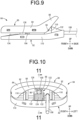
- the connector 64 has a structure in which an upper jaw part 80 and a lower jaw part 82, each of which has a hollow structure, are coupled in a mutually tiltable manner, as shown in FIGS. 6 to 13 .
- the upper jaw part 80 has a hollow structure by combining an upper outer member 84 and an upper inner member 86.
- the upper outer member 84 has a shallow-bottomed cylindrical shape opening downward, and the end (the back part) opposite to the side of the connector 64 connected to the liquid detection sheet 60 (the base sheet 16) constitutes an operating part 88 that slopes upward toward the back.
- the upper inner member 86 has an approximately flat plate shape, and its back end does not reach the back end of the operating part 88.
- the upper outer member 84 and the upper inner member 86 are mechanically coupled to each other by, for example, a locking claw provided at the outer peripheral end of the upper inner member 86 being inserted and locked into a hole opening in the peripheral wall portion of the upper outer member 84.
- the upper outer member 84 and the upper inner member 86 may be fixed to each other by welding or adhesion, for example.
- the upper outer member 84 and the upper inner member 86 are each provided with a plurality of reinforcing ribs 90 protruding from the respective inner surfaces opposed in the vertical direction.
- improvement in deformation rigidity can be achieved by the reinforcing ribs 90 while making the respective outer surfaces of the upper outer member 84 and the upper inner member 86 smooth in shape.
- the number, arrangement, cross-sectional shape, size, etc. of the reinforcing ribs 90 are set appropriately based on, for example, the deformation rigidity required of the upper jaw part 80 or the like.
- a pair of shaft support parts 92, 92 projecting downward are integrally formed in the operating part 88 of the upper outer member 84.
- the shaft support parts 92 are in the form of plates that are opposed to each other in the left-right direction, and include a pair of spindle parts 94, 94 projecting outward in the left-right direction.
- the spindle parts 94 are approximately cylindrical in shape, and the lower portion of the projecting distal end portion is cut diagonally to provide a first guide surface 96 that slopes upward toward the projecting distal end side.
- First support ribs 98 are provided between the opposed pair of shaft support parts 92.
- the first support ribs 98 project downward from the upper outer member 84, and in this practical embodiment, are in the form of a pair of plates that are opposed to each other in the left-right direction.
- the first support rib 98 is penetrated by a first notch 100, which opens downward, in the thickness direction (the left-right direction).
- the internal substrate 102 is housed inside the upper jaw part 80.
- the internal substrate 102 has a structure in which the internal circuit 42 is mounted on an insulating substrate made of resin, for example, by means of printed wiring, etc.
- the internal substrate 102 is a printed circuit board with electronic components attached to a printed wiring board to provide the internal circuit 42 serving as an electric circuit, and is securely supported by machine screws, positioning ribs, or the like to at least one of the upper outer member 84 and the upper inner member 86.
- the internal substrate 102 includes internal terminals 104, 104, 104 projecting downward.
- the internal terminals 104 are electrically connected to the internal circuit 42 on the internal substrate 102, and are exposed downward via through holes 106 that penetrates the upper inner member 86.
- the internal terminals 104, 104, 104 are electrically connected to the first terminal 30 and the second terminals 36, 36 of the first and second detection wirings 66, 68, so that the internal circuit 42 is electrically connected to the first and second terminals 30, 36, 36 via the internal terminals 104, 104, 104.
- the internal circuit 42 is equipped with, for example, a control circuit that applies a detection voltage to the first and second detection wirings 66, 68, a detection circuit that measures the current from the first and second detection wirings 66, 68 to detect disconnection and liquid leakage, a transmission circuit that transmits the detection results to the outside through an external wiring 108 described later or wirelessly, and the like.
- the external wiring 108 connected to the internal circuit 42 is housed inside the upper jaw part 80.
- the external wiring 108 extends forward from the edge on the front side (the lower side in FIG. 8 ) of the internal substrate 102 equipped with the internal circuit 42, which is the side connected to the liquid detection sheet 60, and the extending end is curved and routed inside the connector 64 so as to make a U-turn backward, with the U-turn curved end extends backward along the lateral side of the internal substrate 102, so as to extend backward to the outside from the connector 64 to be exposed.
- the external wiring 108 is curved and extends inside the upper jaw part 80, thereby preventing disconnection of the external wiring 108, disconnection due to breakage of the connected portion between the external wiring 108 and the internal circuit 42, or the like owing to deformation of the curved portion.
- the external wiring 108 can be positioned appropriately inside the connector 64 by utilizing the reinforcing ribs 90 or the like, in order to suppress the transmission of tensile force, which is exerted from the outside, to the connected portion to the internal circuit 42.
- the lower jaw part 82 has a hollow structure in which a lower outer member 110 and a lower inner member 112 are combined.
- the lower outer member 110 and the lower inner member 112 may be mechanically fixed or may be mutually fixed by means of welding, adhesion, or the like.
- a plurality of reinforcing ribs 114 are provided on the respective opposed inner surfaces of the lower outer member 110 and the lower inner member 112.
- improvement in deformation rigidity can be achieved by the reinforcing ribs 114 while making the respective outer surfaces of the lower outer member 110 and the lower inner member 112 smooth in shape.
- the back end of the lower inner member 112 reaches the back end of the lower outer member 110 on the opposite portions in the left-right direction, and does not reach the back end of the lower outer member 110 at the center portion in the left-right direction where a spring member 122, described later, is arranged.
- spindle bearings 116 are provided at the portion of the lower outer member 110 extending backward from the lower inner member 112.
- the spindle bearings 116 are in the form of a pair of opposed plates protruding upward from the lower outer member 110, each of which is penetrated by a shaft insertion hole 118 in the direction of opposition.
- the protruding distal end faces of the pair of spindle bearings 116, 116 constitute second guide surfaces 120 that slope downward toward the inside in the direction of opposition.
- a spring member 122 serving as a urging member is disposed between the opposed faces of the pair of spindle bearings 116, 116.
- the spring member 122 is a torsion coil spring including a tubular intermediate part 124 wound in a spiral shape, and terminal parts 126, 126 on opposite sides protruding peripherally outward from the tubular intermediate part 124.
- the terminal parts 126, 126 extend in mutually different directions that make an angle of approximately 90° in the circumferential direction of the tubular intermediate part 124 in the stationary state in which no external force is acting.
- Each end of the terminal parts 126, 126 is bent and extends in the left-right direction, which is the axial direction of the tubular intermediate part 124.
- One terminal part 126 of the spring member 122 is attached to a second support rib 128.
- the second support rib 128 is integrally formed with the lower outer member 110, and projects upward from the lower outer member 110 behind the lower inner member 112.
- the second support rib 128 is penetrated by a second notch 130, which opens upward, in the thickness direction (the left-right direction).
- the end of the terminal part 126 of the spring member 122 is fitted into the second notch 130 and is rotatably supported.
- a pair of positioning pieces 132, 132 which position the spring member 122 in the left-right direction, are integrally formed with the lower outer member 110.
- the positioning pieces 132, 132 project upward from the lower outer member 110.
- the tubular intermediate part 124 is arranged between the opposed positioning pieces 132, 132, and the contact between the tubular intermediate part 124 and the positioning pieces 132, 132 limits the amount of displacement of the spring member 122 relative to the lower outer member 110 in the left-right direction.
- the second support rib 128, which supports the terminal part 126 of the spring member 122, is disposed between the opposed positioning pieces 132, 132 in the left-right direction.
- the upper surface of the front part of the lower inner member 112 comprises a sloping surface 134 that slopes downward toward the front.
- the lower jaw part 82 has a tapered shape whose thickness dimension in the vertical direction gradually decreases toward the front.
- the upper surface of the back part of the lower inner member 112 spreads in the direction approximately orthogonal to the vertical direction, so that the sloping surface 134 slopes relative to the upper surface of the bark part of the lower inner member 112.
- the left and right opposite end portions of the lower inner member 112 are provided with respective positioning pins 136, 136 protruding upward.
- the positioning pins 136 are integrally formed with the lower inner member 112, and are provided behind the sloping surface 134 (see FIG. 11 ).
- the positioning pin 136 of this practical embodiment is a hollow structure having a tapered outer shape whose diameter decreases toward the projecting distal end.
- the left and right opposite end portions of the upper inner member 86 are penetrated by pin insertion holes 138, 138 through which the positioning pins 136, 136 can be inserted.
- the upper jaw part 80 and the lower jaw part 82 are coupled to each other by insertion of the spindle parts 94, 94 into the shaft insertion holes 118, 118 of the spindle bearings 116, 116.
- the upper jaw part 80 and the lower jaw part 82 are attached to be mutually rotatable around the spindle parts 94, 94, and the front end of the upper jaw part 80 and the front end of the lower jaw part 82 are vertically displaceable relative to each other in the direction of mutual approach and in the direction of mutual separation.
- the spindle parts 94, 94 can be inserted into the shaft insertion holes 118, 118 by a simple operation of bringing the upper jaw part 80 closer to the lower jaw part 82 from above. That is, by bringing the upper jaw part 80 closer to the lower jaw part 82 from above, the first guide surface 96 of each spindle part 94 is pressed against the second guide surface 120 of each spindle bearing 116, and the spindle part 94 enters inside of the spindle bearing 116 in the left-right direction accompanied by elastic deformation of the shaft support part 92 and the spindle bearing 116. When the spindle part 94 reaches the shaft insertion hole 118, elastic deformation of both the shaft support part 92 and the spindle bearing 116 is released, so that the spindle part 94 is inserted into the shaft insertion hole 118.
- the front ends of the upper jaw part 80 and the lower jaw part 82 are urged by the spring member 122 vertically in the direction of mutual approach.
- the upper jaw part 80 With one terminal part 126 of the spring member 122 being inserted in and rotatably supported by the second notch 130 of the second support rib 128 of the lower jaw part 82, the upper jaw part 80 is brought closer to be attached to the lower jaw part 82 from above.
- the other terminal part 126 of the spring member 122 is inserted in and rotatably supported by the first notch 100 of the first support rib 98 of the upper jaw part 80.
- the lower surface of the first support rib 98 slopes upward toward the back, and due to downward displacement of the upper jaw part 80 toward the lower jaw part 82, the other terminal part 126 of the spring member 122 is guided along the lower surface of the first support rib 98 into the first notch 100.
- the spring member 122 can be attached to the jaw parts 80, 82 .
- Such urging force of the spring member 122 acts in the direction in which the back part of the upper jaw part 80 and the back part of the lower jaw part 82 are separated from each other in the vertical direction, and acts on the upper jaw part 80 and the lower jaw part 82 that are allowed to relatively rotate around the spindle part 94, in the direction in which the front parts of the upper jaw part 80 and the lower jaw part 82, which are located in front of the spindle part 94, approach each other. That is, in the connector 64, the front parts of the upper jaw part 80 and the lower jaw part 82 are held closed by the urging force of the spring member 122 when no external force is applied, and the front parts can be opened against the urging force of the spring member 122 by a downward input to the operating part 88.
- the connector 64 is attached to the liquid detection sheet 60 (the base sheet 16) as shown in FIG. 6 . That is, in the open state in which the front ends of the upper jaw part 80 and the lower jaw part 82 of the connector 64 are separated from each other by applying force to the operating part 88, the back end portion of the base sheet 16 is inserted between the upper jaw part 80 and the lower jaw part 82. In the open state of the upper jaw part 80 and the lower jaw part 82, the positioning pins 136, 136 are detached downward from the pin insertion holes 138, 138 of the upper jaw part 80, and the base sheet 16 can pass between the distal ends of the positioning pins 136, 136 and the lower surface of upper jaw part 80. The base sheet 16 is inserted deeper (backward) between the upper jaw part 80 and the lower jaw part 82 until the positioning holes 38, 38 reach a location corresponding to the positioning pins 136, 136.
- the positioning pins 136, 136 are inserted through the positioning holes 38, 38 of the base sheet 16 and the pin insertion holes 138, 138 of the upper jaw part 80, as shown in FIG. 12 .
- the base sheet 16 and the connector 64 are mutually positioned in the planar direction of the base sheet 16 by engagement of the positioning pins 136, 136 and the peripheries of the openings of the positioning holes 38,38.
- the distal end portions of the positioning pins 136, 136 that has passed through the positioning holes 38, 38 are inserted through the pin insertion holes 138, 138 of the upper jaw part 80, thereby preventing the positioning pins 136, 136 from unintentionally slipping out of the positioning holes 38, 38.
- the upper jaw part 80 and the lower jaw part 82 are held in the closed state by being urged by the spring member 122.
- the inserted state of the positioning pins 136, 136 through the positioning holes 38, 38 is maintained with excellent reliability.
- the first and second terminals 30, 36, 36 of the first and second detection wirings 66, 68 are in contact with the internal terminals 104, 104, 104 of the connector 64, and the first and second detection wirings 66, 68 and the internal circuit 42 of the connector 64 are electrically connected. Therefore, the first and second detection wirings 66, 68 are electrically connected to the external wiring 108 via the internal circuit 42 of the connector 64.
- the connector 64 is positioned with respect to the base sheet 16 and is attached to the base sheet 16 with the internal circuit 42 of the connector 64 electrically connected to the first and second detection wirings 66, 68 of the base sheet 16.
- the liquid detection sheet 60 including the connector 64 is laid on a bed for example, and the forearm 5 of the patient 1 is placed on the liquid detection sheet 60 as shown in FIG. 6 .
- the liquid detection sheet 60 is used when detecting bleeding or leakage of liquid medicine from the puncture site of the indwelling needle (the blood collection port 3 and the blood return port 4) indwelled in the forearm 5 of the patient 1.
- the principle of detecting the detection target liquid (the blood, etc.) is the same as that in the first practical embodiment and is not described here.
- the lower jaw part 82 of the connector 64 is configured such that the upper surface of the front part comprises the sloping surface 134 that slopes downward toward the front, which is the distal end attached to the base sheet 16, thereby becoming thinner in the vertical direction toward the front. This makes it easier to insert the lower jaw part 82 between the upper surface of the bed and the lower surface of the base sheet 16 when connecting the connector 64 to the base sheet 16 laid on the bed, thereby facilitating the connection operation of the connector 64.
- the liquid detection sheet 60 of this practical embodiment cannot be turned upside down, since the base sheet 16 is liquid-impermeable, and the right side and the wrong side of the sheet are defined when in use. Therefore, in the liquid detection sheet 60 of this practical embodiment, a logo 140 that is asymmetrical on the right side and the wrong side is printed on the upper surface of the base sheet 16, and the right side and the wrong side of the liquid detection sheet 60 can be grasped by visually checking the said logo 140.
- the liquid detection sheet 60 is illustrated for monitoring bleeding on the left arm of the patient 1, but the liquid detection sheet 60 can also be used for monitoring bleeding on the right arm of the patient 1. Since the base sheet 16 of the liquid detection sheet 60 is liquid-impermeable and cannot be used by being turned upside down, if laid under the right arm, the liquid detection sheet 60 is used in an orientation rotated 180° in the circumferential direction.
- the first and second terminals 30, 36, 36 of the first and second detection wirings 66, 68 are arranged in the center portion in the left-right direction.
- those first and second terminals 30, 36, 36 are configured to be arranged in the center portion in the left-right direction.
- the change in position of the first and second terminals 30, 36, 36 (the connector 64) in the left-right direction is small. This makes it possible to avoid troubles such as an excess length of the external wiring 108 extending from the connector 64 becoming an obstacle, and the external wiring 108 being insufficient in length.
- a first wiring part 142 connected to the first terminal 30 of the first detection wiring 66 and a second wiring part 144a connected to one second terminal 36a of the second detection wiring 68 are connected by a resistor 146.
- the electrical resistance value of the resistor 146 is set larger than the electrical resistance value of the portion short-circuited by the detection target liquid in the liquid detection sheet 60 (the electrical resistance value of the liquid-permeable sheet 18 that has absorbed the detection target liquid between the first and second detection wirings 66, 68).
- the connection state between the connector 64 and the base sheet 16, as well as presence or absence of disconnection in the second detection wiring 68 are checked, and the detection target liquid is detected.
- the detection circuit can be checked by applying a voltage between the first wiring part 142 and the second wiring part 144b in the state where the first and second detection wirings 66, 68 are not short-circuited by the detection target liquid. Specifically, if the connector 64 and the base sheet 16 are not properly connected or if the second detection wiring 68 is disconnected, no current flows, so that the detection current value of the detector 52 becomes zero. Meanwhile, if the connector 64 and the base sheet 16 are properly connected and the second detection wiring 68 is not disconnected, the current flows through a circuit with a high resistance value, including the resistor 146, so that the detector 52 detects a low current value.
- the presence or absence and the magnitude of the detected current can be used to check the connection state between the connector 64 and the base sheet 16 , as well as the presence or absence of disconnection in the second detection wiring 68.
- the first detection wiring 66 is surrounded by the second detection wiring 68, it is unlikely that only the first detection wiring 66 is damaged.
- the second detection wiring 68 is damaged, it is also possible to check whether the first detection wiring 66 is damaged.
- the current flows through a circuit with a law resistance value that does not include the resistor 146, so that the detector 52 detects a higher current value than in the case where there is no short circuit. Therefore, the presence or absence of the detection target liquid in the main detection region 37 of the liquid detection sheet 60 can be determined by the magnitude of the detected current.
- the liquid detection device 62 of this practical embodiment does not need to switch the energization state from the connector 64 to the first and second detection wirings 66, 68 when checking the detection circuit and when monitoring the detection target liquid.
- the liquid detection device 62 of this practical embodiment can simultaneously check the detection circuit and monitor the detection target liquid.
- the resistor 146 is provided at a position outside the main detection region 37 of the liquid detection sheet 60, and in this practical embodiment, the resistor 146 is provided to the internal circuit 42 of the connector 64 that is connected to the base sheet 16. This allows a greater degree of freedom in selecting the resistor 146 than when the resistor is provided in the main detection region 37 of the liquid detection sheet 60. In addition, by arranging the resistor 146 at a position outside the main detection region 37 with which the detection target liquid comes into contact, it is possible to prevent the detection target liquid from sticking to the resistor 146.
- the external wiring 44 of the first practical embodiment includes three core wires comprising conductors that are connected to the first and second terminals 30, 36, 36
- the external wiring 108 of this practical embodiment includes two core wires that are connected to the first and second terminals 30, 36, so that the external wiring 108 can be made thinner.
- the distance between the first detection wiring 66 and the second detection wiring 68 is set within the range of 40 to 100 mm. This makes it possible to reduce the frequency of occurrence of false detection caused by perspiration or the like.
- detection target liquids that accumulate on the liquid-impermeable base sheet 16 in excess of a predetermined amount, such as blood leakage and liquid medicine leakage can be effectively detected by the short circuit between the first and second detection wirings 66, 68.
- the distance between the first detection wiring 66 and the second detection wiring 68 is made approximately constant in the main detection region 37, in which the detection target liquid can be detected, by means of the first curved part 70 and the corner-shaped part 74 of the first detection wiring 66, and the second curved parts 72a, 72b of the second detection wiring 68. Therefore, regardless of the sticking position of the detection target liquid in the main detection region 37 of the liquid detection sheet 60, the lower limit of the detectable liquid amount is stabilized, thereby making it possible to detect the predetermined amount of the detection target liquid in a more reliable manner.
- the liquid detection sheet 60 can detect the detection target liquid with excellent reliability because the base sheet 16 has liquid-impermeable properties that prevent the passage of the detection target liquid so that the detection target liquid accumulates on the base sheet 16. Besides, it is difficult for the detection target liquid to pass through the base sheet 16 and leak downward. Thus, when the liquid detection sheet 60 is laid on the bed, for example, contamination of the bed due to sticking of the detection target liquid will be avoided.
- the liquid detection sheet 60 has a three-layer structure with a small number of layers, in which the first and second detection wirings 66, 68 are formed by printing on the base sheet 16, thereby facilitating manufacture, reducing costs, and the like.
- the liquid-permeable sheet 18 covering the upper surface of the base sheet 16, on which the first and second detection wirings 66, 68 are formed by printing, is made of nonwoven fabric.
- a good tactile feeling can be provided to the upper surface of the liquid detection sheet 60, which is to be in contact with the forearm 5 of the patient 1.
- the detection target liquid is absorbed by the nonwoven fabric and spreads out, thereby inhibiting the detection target liquid from spilling or sticking to the patient 1.
- the base sheet 16 and the liquid-permeable sheet 18 can be adhered to each other utilizing, for example, the heat-welding action of thermoplastic resin or the like, without requiring an adhesive application process.
- the wiring patterns of the first and second detection wirings 22, 24 are merely exemplary and are not limited in particular.
- the remote distance between the first and second detection wirings 22, 24 be as constant as possible.
- the corners may be rounded in an arcuate shape or the like, as shown in the second practical embodiment.
- first and second practical embodiments describe a three-terminal type wiring structure in which one first terminal 30 and two second terminals 36, 36 are provided, but four or more terminals may be provided.
- a four-terminal type wiring structure with two first terminals 30, 30 and two second terminals 36, 36 may be adopted.
- This structure enables checking for disconnection not only in the second detection wiring 24 but also in the first detection wiring 22 by applying a check voltage.
- There may be three or more detection wirings, and a detection voltage may be applied between each of those three or more detection wirings to enable detection of liquid.
- the base sheet 16 protrudes backward from the liquid-permeable sheet 18 and the adhesive sheet 20, and the positioning holes 38 are provided only to the base sheet 16 in the said protruding portion.
- the positioning holes 38 can be provided so as to penetrate not only the base sheet 16 but also the liquid-permeable sheet 18 and the adhesive sheet 20.
- the base sheet 16, the liquid-permeable sheet 18, and the adhesive sheet 20 may have the same size as one another, or alternatively, for example, the liquid-permeable sheet 18 may be larger than the base sheet 16 and protrude radially outward from the base sheet 16.
- the connector attached to the base sheet 16 may be part of the liquid detection sheet 10, or may be a separate component from the liquid detection sheet 10 to constitute the liquid detection device.
- the reinforcing part 40 is provided at the periphery of the opening of the positioning hole 38, but the reinforcing part 40 is not essential. Besides, the reinforcing part 40 does not necessarily have to protrude from the base sheet 16 outward in the thickness direction.
- the reinforcing part 40 can be embedded in the periphery of the opening of the positioning hole 38 in the base sheet 16 so as not to protrude from the base sheet 16 outward in the thickness direction.
- the positioning part is not necessarily limited to the one constituted by a through hole such as the positioning hole 38.
- the preceding first and second practical embodiments show a thin-walled base sheet 16 as an example of the base member.
- the base member is not limited to a thin-walled flexible member such as a sheet or a film, but may be in the form of a plate or the like, for example.
- the base sheet 16 may be made of a liquid-permeable material that allows passage of the detection target liquid.
- a liquid-impermeable sheet as a separate element from the base sheet 16 may be laminated below the base sheet 16 so that the passage of the detection target liquid is prevented below the detection wiring.
- the liquid-impermeable member is not necessarily limited to the one constituted by the base sheet 16.
- the preceding first and second practical embodiments show an example in which the forearm 5 of the patient 1 is placed on the liquid detection sheet 10 so as to extend in the direction approximately parallel to the branched wiring parts 26b, 26c, 32b, 32c, 34 of the first and second detection wirings 22, 24 (in the left-right direction).
- the liquid detection device 12 can also be used with the forearm 5 placed on the liquid detection sheet 10 so as to extend in the direction intersecting the branched wiring parts 26b, 26c, 32b, 32c, 34 of the first and second detection wirings 22, 24 (for example, in the front-back direction).
- the detector 52 shown in FIG. 5 is separate from the artificial dialysis device 2 and is attached to the artificial dialysis device 2 by, for example, being hung by a hook on the artificial dialysis device 2. However, the detector 52 can also be built into the artificial dialysis device 2.
- the preceding first and second practical embodiments show an example of using the liquid detection device 12 including the liquid detection sheet 10 for medical use to detect blood leakage during artificial dialysis.
- the liquid detection sheet 10 can also be used to detect liquid leakage during, for example, infusion or medication.
- the detection target liquid to be detected using the liquid detection sheet 10 for medical use is not limited to blood, but may also be, for example, biological fluids in the human body (biological fluids in a broad sense including liquids secreted in the body (such as saliva) and liquids excreted outside the body (such as urine)), medical liquids such as liquid medicine and infusion liquid, and the like.
- the preceding first and second practical embodiments show an example in which the blood 6 is detected when the blood 6 touches both the first detection wiring 22 (66) and the second detection wiring 24 (68), causing those first detection wiring 22 (66) and second detection wiring 24 (68) to be mutually conducted.
- a detection target liquid detectable with the detection target liquid such as blood being remote from at least one of the first detection wiring 22 (66) and the second detection wiring 24 (68).
- the presence of the detection target liquid may be detected based on a change in the electrical connection state between the first detection wiring 22 (66) and the second detection wiring 24 (68) (for example, a change in electrical resistance value) due to the detection target liquid approaching the detection wiring in a state of separation.
Landscapes
- Health & Medical Sciences (AREA)
- Heart & Thoracic Surgery (AREA)
- Vascular Medicine (AREA)
- Biomedical Technology (AREA)
- Engineering & Computer Science (AREA)
- Life Sciences & Earth Sciences (AREA)
- Animal Behavior & Ethology (AREA)
- General Health & Medical Sciences (AREA)
- Public Health (AREA)
- Veterinary Medicine (AREA)
- Anesthesiology (AREA)
- Cardiology (AREA)
- Hematology (AREA)
- External Artificial Organs (AREA)
Abstract
Description
- This invention relates to a liquid detection sheet for medical use, which is used to detect blood leakage, etc. in the medical field.
- In the medical field, it is sometimes necessary to detect leakage of blood or other liquids at an early stage when they occur. For example, during dialysis or infusion, liquid leakage may occur when the needle slips out from the patient and blood or liquid medicine leaks from the puncture site, and it is necessary to detect and deal with the leak before it becomes a major problem. However, it is not practical for busy medical personnel to continuously monitor dialysis, infusion, and other procedures from start to finish, so the use of liquid detection devices that automatically detect liquid leakage is being considered.
- Conventionally, for example, Japanese Unexamined Patent Publication No.
JP-A-2012-196293 - Patent Document 1:
JP-A-2012-196293 - However, with conventional liquid detection devices, before use, it is necessary to check that there are no disconnections in either of the two detection wirings that are routed in parallel. Since a relatively large check voltage is required, checking before use is troublesome.
- Besides, perspiration, etc. of a patient may be mistakenly detected as the occurrence of liquid leakage, and there is a need to avoid false detection of liquids that do not need to be detected, such as perspiration, while effectively detecting detection target liquids such as blood and liquid medicine.
- In addition, in
Patent Document 1, since the sheet that constitutes the liquid detection region has a six-layer structure, the number of parts is large and the manufacturing is time-consuming. - Further, in conventional liquid detection devices, an external circuit is generally connected to the two detection wirings via a detachable connector, but there is a risk that the connector may not be properly connected electrically due to such factors as being connected at an angle. In addition, since the connector is often subjected to external force, there is a risk of misalignment of the connector or disconnection in the wiring of the connector. There was also a need to make it possible to easily attach the connector to the sheet that constitutes the liquid detection area.
- It is an object of the present invention to provide a liquid detection sheet for medical use of novel structure which is able to solve at least one of the problems inherent in conventional liquid detection devices as described above.
- Hereinafter, preferred embodiments for grasping the present invention will be described. However, each preferred embodiment described below is exemplary and can be appropriately combined with each other. Besides, a plurality of elements described in each preferred embodiment can be recognized and adopted as independently as possible, or can also be appropriately combined with any element described in other preferred embodiments. By so doing, in the present invention, various other preferred embodiments can be realized without being limited to those described below.
- A first preferred embodiment provides a liquid detection sheet for medical use comprising: a base member having electric insulation properties; and a first detection wiring and a second detection wiring provided remote from each other on the base member, the liquid detection sheet being configured to detect leakage of a detection target liquid such as blood based on a change in an electrical connection state between the first detection wiring and the second detection wiring due to sticking of the detection target liquid, wherein a main detection region in which the first detection wiring and the second detection wiring extend substantially parallel to each other is provided on the base member, and a distance between the first detection wiring and the second detection wiring opposed to each other in the main detection region is set within a range of 40 to 100 mm.
- According to the liquid detection sheet for medical use structured following the present preferred embodiment, the distance between the first detection wiring and the second detection wiring opposed to each other in the main detection region is set within the range of 40 to 100 mm. This makes it difficult to detect a relatively small amount of liquid, such as perspiration, while making it possible to effectively detect the detection target liquid that has accumulated to a certain amount on the base member. Therefore, the desired detection target liquid can be detected with high accuracy so as to detect, for example, highly dangerous blood leakage or the like with high reliability, and the frequency of occurrence of false detection caused by perspiration or the like can be reduced.
- A second preferred embodiment provides a liquid detection sheet for medical use comprising: a base member having electric insulation properties; and a plurality of detection wirings provided remote from each other on the base member, the liquid detection sheet being configured to detect leakage of a detection target liquid such as blood based on a change in an electrical connection state between the plurality of detection wirings due to sticking of the detection target liquid, wherein an upper surface of the base member on which the plurality of detection wirings are formed by printing is covered with nonwoven fabric, and the base member and the nonwoven fabric are adhered to each other by a heat-welding sheet.
- According to the liquid detection sheet for medical use structured following the present preferred embodiment, the detection wirings are formed by printing on the base member, so that the liquid detection sheet has a three-layer structure with a small number of layers, thereby facilitating manufacturing, reducing costs, and the like. In addition, by providing nonwoven fabric covering the upper surface of the base member on which the detection wirings are formed by printing, a good tactile feeling can be provided to the portion of the liquid detection sheet which is to be in contact with the forearm of the patient or the like. Besides, the detection target liquid is absorbed by the nonwoven fabric and spreads out, thereby inhibiting the detection target liquid from spilling or sticking to the patient. In addition, by heating the heat-welding sheet with the base member, the heat-welding sheet, and the nonwoven fabric laminated, the base member and the nonwoven fabric can be adhered to each other without requiring an adhesive application process.
- A third preferred embodiment provides a liquid detection sheet for medical use comprising: a base member having electric insulation properties; and a plurality of detection wirings provided remote from each other on the base member, the liquid detection sheet being configured to detect leakage of a detection target liquid such as blood based on a change in an electrical connection state between the plurality of detection wirings due to sticking of the detection target liquid, wherein a liquid-impermeable member that prevents passage of the detection target liquid is arranged below the plurality of detection wirings.
- According to the liquid detection sheet for medical use structured following the present preferred embodiment, it is difficult for the detection target liquid to pass through the liquid-impermeable member and leak downward, thereby detecting the detection target liquid that accumulates on the liquid-impermeable member with excellent reliability. In addition, by keeping the detection target liquid on the liquid-impermeable member, contamination of the bed due to sticking of the detection target liquid will be avoided, for example, when the liquid detection sheet is laid on the bed.
- A fourth preferred embodiment provides the liquid detection sheet for medical use according to the third preferred embodiment, wherein terminals of the plurality of detection wirings are located at a widthwise center portion of the base member in an outer peripheral end of the base member.
- The liquid detection sheet including the liquid-impermeable member cannot be used by being turned upside down. Thus, for example, if the terminals of the detection wirings, which are located at the outer peripheral end of the base member, are arranged biasedly in the width direction of the base member, the distance from the terminals of the detection wirings to the external device will change between the case where the liquid detection sheet is used by being laid below the left arm of the patient and the case where the liquid detection sheet is used by being laid below the right arm of the patient, thereby causing differences in the required length and handling of the external wiring connected to the terminals of the detection wirings. According to the liquid detection sheet structured following the present preferred embodiment, the terminals of the detection wirings are located at the widthwise center portion of the base member. Thus, even if it is not possible to use the liquid detection sheet by turning upside down, the difference in the handling of the external wiring is minimized between the case where the liquid detection sheet is used on the left side of the patient and the case where the liquid detection sheet is used on the right side of the patient, for example, and in both cases, the external wiring is less likely to become an obstacle.
- A fifth preferred embodiment provides a liquid detection sheet for medical use comprising: a base member having electric insulation properties; and a first detection wiring and a second detection wiring provided remote from each other on the base member, the liquid detection sheet being configured to detect leakage of a detection target liquid such as blood based on a change in an electrical connection state between the first detection wiring and the second detection wiring due to sticking of the detection target liquid, wherein the second detection wiring is provided so as to surround the first detection wiring on the base member.
- According to the liquid detection sheet for medical use structured following the present preferred embodiment, by connecting a check circuit to the two ends of the second detection wiring, the electrical state of the second detection wiring (disconnection, etc.) can be checked by applying a small check voltage. Besides, since the first detection wiring has a specific wiring mode with respect to the second detection wiring, the normal condition of the first detection wiring can be estimated by checking the second detection wiring.
- That is, damage such as disconnection of the first detection wiring or the second detection wiring is generally caused by bending of the detection sheet. Here, in the present preferred embodiment, the first detection wiring and the second detection wiring, which detect the liquid by means of a change in the electrical connection state therebetween, are configured such that the second detection wiring surrounds the first detection wiring relatively nearby. Thus, bending of the first detection wiring is accompanied by bending of the second detection wiring, and disconnection due to bending of the first detection wiring alone is difficult to assume. Therefore, if the first detection wiring is disconnected due to bending of the base member, for example, the second detection wiring surrounding the first detection wiring will also be disconnected. Accordingly, the electrical state of the first detection wiring can be estimated by checking the electrical state of the second detection wiring.
- In this way, the electrical abnormalities such as disconnection of the first detection wiring can be checked based on the electrical state of the second detection wiring, thereby making it easier to check the first and second detection wirings.
- A sixth preferred embodiment provides the liquid detection sheet for medical use according to the fifth preferred embodiment, wherein the first detection wiring and the second detection wiring are each imparted with a comb teeth-like shape by opposite wiring parts extending substantially parallel to each other and a plurality of branched wiring parts extending from the respective opposite wiring parts in a direction of opposition of the opposite wiring parts, and the plurality of branched wiring parts of the first detection wiring and the plurality of branched wiring parts of the second detection wiring are arranged in a length direction of the opposite wiring parts so as to interdigitate with one another in the direction of opposition of the opposite wiring parts.
- According to the liquid detection sheet for medical use structured following the present preferred embodiment, it is possible to prevent the spacing between the first detection wiring and the second detection wiring from becoming too large, thereby detecting the detection target liquid with high accuracy. Besides, the branched wiring parts interdigitate with one another in the direction of opposition of the opposite wiring parts, and the branched wiring parts are arranged in the length direction of the opposite wiring parts. This makes it possible to efficiently obtain a relatively large effective detection area.
- A seventh preferred embodiment provides the liquid detection sheet for medical use according to the fifth or sixth preferred embodiment, wherein a first terminal is provided at one end portion of the first detection wiring, a pair of second terminals are provided at two end portions of the second detection wiring, and the first terminal and the pair of second terminals are arranged side by side in a straight line, and the first terminal is located between the pair of second terminals.
- According to the liquid detection sheet for medical use structured following the present preferred embodiment, the first terminal provided at one end portion of the first detection wiring and the pair of second terminals provided at the two end portions of the second detection wiring are arranged side by side in a straight line, which facilitates connection of the detection circuit to the first terminal and the second terminals. In particular, the arrangement of the first terminal between the pair of second terminals makes it easier to arrange the second detection wiring so as to surround the first detection wiring.
- An eighth preferred embodiment provides the liquid detection sheet for medical use according to any one of the fifth through seventh preferred embodiments, wherein the base member comprises a base sheet that is impermeable to the detection target liquid, the first detection wiring and the second detection wiring are formed by printing on an upper surface of the base sheet, and a liquid-permeable sheet that has electric insulation properties and allows passage of the detection target liquid is provided on the upper surface of the base sheet so as to cover the first detection wiring and the second detection wiring.
- According to the liquid detection sheet for medical use structured following the present preferred embodiment, the detection target liquid accumulates on the base sheet because the base sheet is impermeable to the detection target liquid. Therefore, the amount of the detection target liquid on the base sheet gradually increases and the area of the detection target liquid on the base sheet becomes larger, which increases the possibility of the detection target liquid touching both the first detection wiring and the second detection wiring to be detected. Besides, the base sheet, which does not require liquid-permeable properties, can easily be made smooth, and by the first and second detection wirings being formed by printing on the base sheet, disconnection or the like of the first and second detection wirings due to printing defects is unlikely to occur.
- The liquid-permeable sheet having liquid-permeable properties is overlapped on the base sheet, and the liquid-permeable sheet diffusely transmits the detection target liquid sticking from above. This facilitates conduction by the detection target liquid between the first and second detection wirings, thereby increasing the reliability of detection. Furthermore, since the flow of the detection target liquid on the base sheet is limited by the liquid-permeable sheet, the detection target liquid is unlikely to spill out of the base sheet and is easier to detect by accumulating on the base sheet, while avoiding contamination of the surrounding area by the detection target liquid. Additionally, the liquid-permeable sheet covering the first and second detection wirings formed by printing on the base sheet has electric insulation properties. Thus, even if the body of the patient comes into contact with the liquid-permeable sheet, for example, the body of the patient will not cause conduction between the first and second detection wirings, thereby preventing false detection.
- A ninth preferred embodiment provides the liquid detection sheet for medical use according to any one of the fifth through eighth preferred embodiments, further comprising a state checking member connected to the two end portions of the second detection wiring and configured to check an electrical state of the second detection wiring by applying a check voltage to the second detection wiring.
- According to the liquid detection sheet for medical use structured following the present preferred embodiment, the state checking member is connected to the two end portions of the second detection wiring, thereby checking the electrical state of the second detection wiring with a relatively small check voltage.
- A tenth preferred embodiment provides a liquid detection sheet for medical use comprising: a base member having electric insulation properties; and a plurality of detection wirings provided remote from each other on the base member, the liquid detection sheet being configured to detect leakage of a detection target liquid such as blood based on a change in an electrical connection state between the plurality of detection wirings due to sticking of the detection target liquid, wherein the plurality of detection wirings are connected to each other by a resistor at a position outside a main detection region configured to detect the leakage of the detection target liquid.
- According to the liquid detection sheet for medical use structured following the present preferred embodiment, based on differences in energization resistance, checking for disconnection of the detection wirings and detection of the liquid can be performed by the same application mode of voltage.
- Besides, for example, the resistor can be provided in the internal circuit of a connector connected to the liquid detection sheet, which provides a greater degree of freedom in selecting a resistor compared to the case where the resistor is provided in the main detection region of the liquid detection sheet. In addition, by arranging the resistor at a position outside the main detection region with which the detection target liquid comes into contact, the detection target liquid can be prevented from touching the resistor.
- An eleventh preferred embodiment provides a liquid detection sheet for medical use comprising: a base member having electric insulation properties; and a first detection wiring and a second detection wiring provided remote from each other on the base member, the liquid detection sheet being configured to detect leakage of a detection target liquid such as blood based on a change in an electrical connection state between the first detection wiring and the second detection wiring due to sticking of the detection target liquid, wherein one of the first detection wiring and the second detection wiring includes a curved part spaced outward from an end of the other of the first detection wiring and the second detection wiring and extending in an arc-like shape.
- According to the liquid detection sheet for medical use structured following the present preferred embodiment, in the length direction of one of the first and second detection wirings, the change in the remote distance between the aforementioned one detection wiring and the other of the first and second detection wirings is reduced, and the change in the amount of the detection target liquid that is detectable in the length direction of the one detection wiring can be minimized, thereby achieving highly reliable liquid detection.
- A twelfth preferred embodiment provides a liquid detection sheet for medical use comprising: a base member having electric insulation properties; and a plurality of detection wirings provided remote from each other on the base member, the liquid detection sheet being configured to detect leakage of a detection target liquid such as blood based on a change in an electrical connection state between the plurality of detection wirings due to sticking of the detection target liquid, wherein terminals of the plurality of detection wirings are arranged side by side in an outer peripheral portion of the base member, and positioning parts are provided to the base member on opposite sides in a direction of arrangement of the terminals and located close to the terminals, the positioning parts positioning a connector with respect to the base member, the connector including an external wiring electrically connected to the terminals.
- According to the liquid detection sheet for medical use structured following the present preferred embodiment, the base member and the connector are positioned by the positioning parts at the locations close to the pair of terminals located at the two ends in the direction of arrangement of the terminals, so that the connector is properly positioned with respect to the pair of terminals at the two ends.
- Besides, when there is an intermediate terminal between the pair of terminals at the two ends, the proper positioning of the connector with respect to the pair of terminals at the two ends also ensures that the connector is properly positioned with respect to the intermediate terminal located between the pair of terminals at the two ends. This makes it possible to stably connect the internal circuit of the connector with respect to all of the plurality of terminals.
- Even if external force acts between the connector and the base member in the direction of pulling away from each other, unintended detachment of the connector and the base member is prevented, thereby maintaining the electrical connection state between the connector and the base member, and hence between the external wiring of the connector and the first and second detection wirings on the base member.
- A thirteenth preferred embodiment provides the liquid detection sheet for medical use according to the twelfth preferred embodiment, wherein the base member comprises a base sheet that is impermeable to the detection target liquid, and the base sheet is provided with a positioning hole through which a positioning pin protruding from the connector is inserted, and the positioning parts include the positioning hole.
- According to the liquid detection sheet for medical use structured following the present preferred embodiment, a proper connection between the plurality of terminals provided on the base sheet and the internal circuit of the connector is easily achieved by a simple structure in which the positioning pin on the connector side is inserted through the positioning hole of the base sheet. In particular, when the base member is a thin-walled base sheet, the positioning hole is easy to form and the positioning action is effectively achieved.
- A fourteenth preferred embodiment provides the liquid detection sheet for medical use according to the thirteenth preferred embodiment, wherein an annular reinforcing part is provided at a periphery of an opening of the positioning hole of the base sheet, the annular reinforcing part protruding in a thickness direction of the base sheet.
- According to the liquid detection sheet for medical use structured following the present preferred embodiment, when the positioning pin is pressed against the inner circumferential surface of the positioning hole by the action of external force, damage such as tearing of the base sheet is prevented by the reinforcing part. In addition, since the length of the positioning hole provided to the thin-walled base sheet is increased by the reinforcing part, the contact area between the positioning pin and the positioning hole is enlarged, which makes it possible to obtain the positioning action more advantageously and to expect improved durability due to dispersion of stress.
- A fifteenth preferred embodiment provides a liquid detection sheet for medical use comprising: a base member having electric insulation properties; and a plurality of detection wirings provided remote from each other on the base member, the liquid detection sheet being configured to detect leakage of a detection target liquid such as blood based on a change in an electrical connection state between the plurality of detection wirings due to sticking of the detection target liquid, wherein a connector including an internal circuit electrically connected to terminals of the plurality of detection wirings is provided, and an external wiring electrically connected to the internal circuit of the connector and extending to an outside from the connector is configured such that the external wiring extends from the internal circuit to a side on which the connector is connected to the terminals, and an extending end of the external wiring curves so as to make a U-turn and extends to the outside from the connector on a side opposite to the side on which the connector is connected to the terminals.
- According to the liquid detection sheet for medical use structured following the present preferred embodiment, the external wiring extends from the internal circuit to the side on which the connector is connected to the terminals and the extending end of the external wiring curves so as to make a U-turn. Thus, for example, when the external wiring is pulled by the action of external force, damage to the external wiring itself or to the connected portion between the external wiring and the internal circuit or the like is prevented owing to deformation of the curved portion.
- A sixteenth preferred embodiment provides a liquid detection sheet for medical use comprising: a base member having electric insulation properties; and a plurality of detection wirings provided remote from each other on the base member, the liquid detection sheet being configured to detect leakage of a detection target liquid such as blood based on a change in an electrical connection state between the plurality of detection wirings due to sticking of the detection target liquid, wherein a connector including an internal circuit electrically connected to terminals of the plurality of detection wirings is provided, a distal end portion of the connector includes an upper jaw part and a lower jaw part that are relatively displaceable in a direction of mutual separation and in a direction of mutual approach, an external wiring is electrically connected to the terminals via the internal circuit of the connector by an outer peripheral portion of the base member being clasped between the upper jaw part and the lower jaw part in a vertical direction, and the lower jaw part of the connector arranged below the base member is configured such that an upper surface comprises a sloping surface that slopes downward toward a distal end of the connector attached to the base member whereby the lower jaw part becomes thinner in the vertical direction toward the distal end of the connector attached to the base member.
- According to the liquid detection sheet for medical use structured following the present preferred embodiment, the lower jaw part becomes thinner in the vertical direction toward the distal end of the connector attached to the base member. This makes it easy to insert the lower jaw part of the connector into the under part of the base member placed on the bed, thereby facilitating connection operation of the connector to the base member placed on the bed.
- A seventeenth preferred embodiment provides the liquid detection sheet for medical use according to the sixteenth preferred embodiment, wherein the connector includes an urging member that urges distal end portions of the upper jaw part and the lower jaw part attached to the base member in the direction of mutual approach.
- According to the liquid detection sheet for medical use structured following the present preferred embodiment, the upper jaw part and the lower jaw part are urged in the direction of mutual approach by the urging member. Thus, the connector can be easily attached to the base member by clasping the base member between the upper and lower jaw parts by means of urging force of the urging member. Moreover, since the connector is maintained in the attached state to the base member by the urging force exerted on the upper and lower jaw parts by the urging member, no special locking operation or the like is required.
- According to the present invention, the detection target liquid can be detected with high accuracy while suppressing false detection of, for example, perspiration of a patient or the like that does not require detection.
-
-
FIG. 1 is a plan view of a liquid detection device including a liquid detection sheet for medical use according to a first practical embodiment of the present invention. -
FIG. 2 is a cross sectional view taken along line 2-2 ofFIG. 1 . -
FIG. 3 is a cross sectional view of the liquid detection device shown inFIG. 1 , corresponding to a cross section taken along line 3-3 ofFIG. 1 . -
FIG. 4 is a view suitable for explaining a laminated structure of the liquid detection sheet shown inFIG. 1 . -
FIG. 5A is a view suitable for explaining the liquid detection device shown inFIG. 1 in use, illustrating the state in which no blood leakage is detected. -
FIG. 5B is a view suitable for explaining the liquid detection device shown inFIG. 1 in use, illustrating the state in which blood leakage is detected. -
FIG. 6 is a plan view of a liquid detection device including a liquid detection sheet for medical use according to a second practical embodiment of the present invention. -
FIG. 7 is a perspective view of a connector constituting the liquid detection device shown inFIG. 6 . -
FIG. 8 is a plan view of the connector shown inFIG. 7 . -
FIG. 9 is a right side view of the connector shown inFIG. 7 . -
FIG. 10 is a rear view of the connector shown inFIG. 7 . -
FIG. 11 is a cross sectional view taken along line 11-11 ofFIG. 10 . -
FIG. 12 is a cross sectional view taken along line 12-12 ofFIG. 9 . -
FIG. 13 is a cross sectional view taken along line 13-13 ofFIG. 9 . -
FIG. 14 is a view diagrammatically showing connection between a detection wiring and an internal circuit of the connector in the liquid detection device shown inFIG. 6 . - Hereinafter, practical embodiments of the present invention will be described with reference to the drawings.
-
FIGS. 1 to 3 show aliquid detection device 12 including aliquid detection sheet 10 for medical use according to a first practical embodiment of the present invention. Theliquid detection device 12 has a structure in which aconnector 14 is attached to theliquid detection sheet 10. In the following description, as a general rule, the vertical direction refers to the vertical direction inFIG. 3 , which is the vertical direction in the state of use, the front-back direction refers to the vertical direction inFIG. 1 , and the left-right direction refers to the left-right direction inFIG. 1 . In the drawings, the thickness of the components, the width of the detection wirings, and the like are exaggerated for illustrative purposes. - As shown in
FIG. 4 , theliquid detection sheet 10 has a laminated structure in which abase sheet 16 serving as a base member and a liquid-permeable sheet 18 overlapped on the upper surface of thebase sheet 16 are fastened to each other by anadhesive sheet 20. - The
base sheet 16 is in the form of a thin-walled sheet or film. Thebase sheet 16 is a liquid-impermeable member having liquid-impermeable properties that is not permeable to liquids such as blood. Thebase sheet 16 is made of an electrically insulating material. Thebase sheet 16 is made of a synthetic resin material, for example, and specifically, can be made of polyethylene terephthalate (PET). It is desirable that the thickness of thebase sheet 16 be 0.01 mm to 0.5 mm from the viewpoint of, for example, minimizing sense of discomfort (stiffness) when a patient places his/her arm or the like on theliquid detection sheet 10 while ensuring the necessary electric insulation properties, and in this practical embodiment, the thickness is 0.05 mm, for example. - On the
base sheet 16, afirst detection wiring 22 and asecond detection wiring 24 are provided. Both thefirst detection wiring 22 and thesecond detection wiring 24 are made of a conductive material, for example, a conductive paste made of a synthetic resin material mixed with a conductive filler made of a conductive material such as metal and carbon. Thefirst detection wiring 22 and thesecond detection wiring 24 made of a conductive paste are each formed by printing in a predetermined shape (pattern) on the upper surface of thebase sheet 16. Accordingly, the liquid-impermeable base sheet 16 is arranged below thefirst detection wiring 22 and thesecond detection wiring 24. - As shown in
FIG. 1 , thefirst detection wiring 22 includes a firstcentral detection part 26 having a laterally rotated U shape with the left side open at the center portion of thebase sheet 16, and also includes aterminal connecting part 28 extending straightly from the firstcentral detection part 26 toward the back of thebase sheet 16. At the back end of theterminal connecting part 28 in thefirst detection wiring 22, there is provided afirst terminal 30 that is located at the back end of thebase sheet 16 and is electrically connected to theconnector 14 described below. - The
second detection wiring 24 is arranged remote from thefirst detection wiring 22 and is provided so as to surround thefirst detection wiring 22. That is, thesecond detection wiring 24 includes an outercircumferential detection part 32 surrounding the firstcentral detection part 26 of thefirst detection wiring 22, and also includes a secondcentral detection part 34 extending from the outercircumferential detection part 32 so as to be inserted into the left side opening of the firstcentral detection part 26 of thefirst detection wiring 22. The outercircumferential detection part 32 of thesecond detection wiring 24 is arranged such that its two end portions are disposed remote from each other on the left-right opposite sides of theterminal connecting part 28 of thefirst detection wiring 22 and are located at the back end of thebase sheet 16. A pair ofsecond terminals circumferential detection part 32 of thesecond detection wiring 24. The pair ofsecond terminals first terminal 30, and thosefirst terminal 30 andsecond terminals first terminal 30 and thesecond terminals first terminal 30 and thesecond terminals base sheet 16 in the left-right width direction, and more suitably, they are provided approximately lineally symmetrically with respect to the left-right center line of thebase sheet 16. This allows theconnector 14 to be positioned at the center portion of thebase sheet 16 in the left-right direction, with theconnector 14 positioned on the opposite side (outside) of the body of a patient (1), regardless of whether theliquid detection sheet 10 is used on the right or left forearm (5) of the patient (1) in the state of use described below. Thus, for example, the distance from theconnector 14 to a detector (52), which is described below, does not change significantly, making it easier to avoid excessive or insufficient wiring length. - A
left end 32a of the outercircumferential detection part 32 in thesecond detection wiring 24 extends in the front-back direction, and is approximately parallel to aright end 26a of the firstcentral detection part 26 in thefirst detection wiring 22, which extends in the front-back direction, so as to be opposite to each other in the left-right direction. Theright end 26a extending in the front-back direction in the firstcentral detection part 26 and theleft end 32a extending in the front-back direction in the outercircumferential detection part 32 serve as opposite wiring parts of this practical embodiment. The firstcentral detection part 26 includes front andback ends right end 26a. On the front-back opposite outer sides of the firstcentral detection part 26, there are arranged front andback ends circumferential detection part 32 extending rightward from theleft end 32a of the outercircumferential detection part 32. Between the front andback ends central detection part 26, the secondcentral detection part 34 extends rightward from theleft end 32a of the outercircumferential detection part 32. In this way, thefirst detection wiring 22 and thesecond detection wiring 24 include branchedwiring parts opposite wiring parts opposite wiring parts first detection wiring 22 and thesecond detection wiring 24 are each imparted with an approximately comb-teeth shape in the portions constituted by theopposite wiring parts branched wiring parts branched wiring parts first detection wiring 22 and thebranched wiring parts second detection wiring 24 are arranged alternately at approximately regular intervals in the front-back direction so as to interdigitate with one another in the left-right direction. - Therefore, the
right end 26a in the firstcentral detection part 26 of thefirst detection wiring 22 and theleft end 32a in the outercircumferential detection part 32 of thesecond detection wiring 24 extend parallel to each other, while the front andback ends central detection part 26 and the front andback ends central detection part 34 of thesecond detection wiring 24 extend parallel to one another. Accordingly, those portions in the first andsecond detection wirings main detection region 37 of this practical embodiment. Themain detection region 37 of this practical embodiment is set to the radially inner portion of theliquid detection sheet 10 surrounded by the outercircumferential detection part 32 of thesecond detection wiring 24. In this practical embodiment, theright end 26a of the firstcentral detection part 26 and theright end 32d of the outercircumferential detection part 32 are mutually remote and extend in parallel, and the remote distance therebetween is approximately the same as the remote distance D between the front andback ends central detection part 26 and the front andback ends circumferential detection part 32 as well as the secondcentral detection part 34. Theright end 26a of the firstcentral detection part 26 and theright end 32d of the outercircumferential detection part 32 also constitute themain detection region 37. - The
first detection wiring 22 and thesecond detection wiring 24 are remote from each other on thebase sheet 16, and the distance D between the firstcentral detection part 26 of thefirst detection wiring 22 and the outercircumferential detection part 32 as well as the secondcentral detection part 34 of thesecond detection wiring 24 opposed to each other (the distance of opposition in the main detection region 37) is set within the range of 40 mm to 100 mm. In this practical embodiment, the firstcentral detection part 26 of thefirst detection wiring 22, and the outercircumferential detection part 32 as well as the secondcentral detection part 34 of thesecond detection wiring 24 both have a configuration constituted by combination of a plurality of straight portions (theright end 26a, thefront end 26b, and theback end 26c in thefirst detection wiring 22, and theleft end 32a, thefront end 32b, and theback end 32c, theright end 32d, and the secondcentral detection part 34 in the second detection wiring 24). The distance D between the firstcentral detection part 26 of thefirst detection wiring 22 and the outercircumferential detection part 32 as well as the secondcentral detection part 34 of thesecond detection wiring 24 opposed to each other refers to the distance between the straight portions of the firstcentral detection part 26, the outercircumferential detection part 32 and the secondcentral detection part 34 that extend approximately parallel to one another. In this practical embodiment, the distance D between the straight portions of the firstcentral detection part 26, the outercircumferential detection part 32 and the secondcentral detection part 34 is approximately constant. However, the distance between the straight portions of the firstcentral detection part 26, the outercircumferential detection part 32 and the secondcentral detection part 34 may be different for each straight portion, in which case the minimum distance between the straight portions is 40 mm or more and the maximum distance between the straight portions is 100 mm or less. - The back end of the
base sheet 16 is provided with a pair of positioning holes 38, 38 serving as a positioning part. The positioning holes 38 perforate thebase sheet 16 in the thickness direction, and have, for example, a circular cross-section. The pair of positioning holes 38, 38 are arranged remote from each other in the left-right direction, and are located on the left-right opposite outer sides of the pair ofsecond terminals positioning hole 38 is arranged close to thesecond terminal 36 in the left-right direction. For example, the distance between thepositioning hole 38 and thesecond terminal 36 arranged adjacently is 30 mm or less, more suitably 15 mm or less. - An annular reinforcing
part 40 is provided at the periphery of the opening of eachpositioning hole 38. The reinforcingpart 40 is provided at the periphery of the opening of thepositioning hole 38 so as to protrude outward in the thickness direction of thebase sheet 16. The reinforcingpart 40 is formed of, for example, synthetic resin or metal, and the deformation rigidity of thebase sheet 16 is increased at the portion where the reinforcingpart 40 is provided. The reinforcingpart 40 may be formed integrally with thebase sheet 16 or may be formed as a separate member from thebase sheet 16 and fastened to thebase sheet 16 by welding or other means. In this practical embodiment, the reinforcingparts 40 are provided at the peripheries of the openings on both the upper and lower sides of the positioning holes 38, but may be provided only at the periphery of the opening on either the upper or lower side, for example. - The liquid-
permeable sheet 18 has liquid-permeable properties to allow passage of a detection target liquid, such as blood, and is also has electric insulation properties. The liquid-permeable sheet 18 may be woven or knitted fabric, but is constituted by, for example, nonwoven fabric. As shown inFIG. 4 , the liquid-permeable sheet 18 is overlapped on the upper surface of thebase sheet 16, and covers thefirst detection wiring 22 and thesecond detection wiring 24 provided on the upper surface of thebase sheet 16. The liquid-permeable sheet 18 has approximately the same dimensions in the left-right direction and shorter dimensions in the front-back direction compared to thebase sheet 16, and the back end portion of thebase sheet 16 protrudes backward from the liquid-permeable sheet 18 to be exposed. Thus, thefirst terminal 30 and thesecond terminals permeable sheet 18, but are exposed to the outside behind the liquid-permeable sheet 18. In this practical embodiment, the pair of positioning holes 38, 38 arranged on the left-right opposite outer sides of thesecond terminals permeable sheet 18, and are formed only on thebase sheet 16. - The
base sheet 16 and the liquid-permeable sheet 18 are coupled to each other by theadhesive sheet 20 serving as an adhesive layer. Theadhesive sheet 20 is, for example, a synthetic resin sheet with glue layers on both sides. One glue layer is adhered to thebase sheet 16 and the other glue layer is adhered to the liquid-permeable sheet 18, thereby holding thebase sheet 16 and the liquid-permeable sheet 18 in an overlapped state. Theadhesive sheet 20 has liquid-permeable properties to allow passage of the detection target liquid. Theadhesive sheet 20 may be, for example, a heat-welding sheet. The heat-welding sheet is made of thermoplastic resin such as polyimide, polyester, or polyurethane, for example, and becomes adhesive upon heating and solidifies upon cooling. Therefore, thebase sheet 16 and the liquid-permeable sheet 18 can be adhered to each other by heating the heat-welding sheet and then cooling it, with the heat-welding sheet (the adhesive sheet 20) overlapped on the upper surface of thebase sheet 16 and interposed between thebase sheet 16 and the liquid-permeable sheet 18. The adhesive sheet 20 (the heat-welding sheet) is able to allow passage of the detection target liquid by, for example, being made in a mesh pattern, even if it is not made of a liquid-permeable material. Thebase sheet 16 and the liquid-permeable sheet 18 may be coupled to each other by an adhesive, for example, without using theadhesive sheet 20. The heat-welding sheet may be formed by thermosetting resin such as epoxy resin. - The
connector 14 is attached to theliquid detection sheet 10 having such a structure. Theconnector 14 includes an internal circuit 42 (seeFIG. 3 ) which is connected to thefirst detection wiring 22 and thesecond detection wiring 24 of theliquid detection sheet 10, and includes anexternal wiring 44 which is electrically connected to theinternal circuit 42 and extends to the outside. Theinternal circuit 42 of theconnector 14 is connected via theexternal wiring 44 to adetector 52 outside (described later). - The
connector 14 is attached to the back end portion of theliquid detection sheet 10. That is, theconnector 14 includes alower jaw part 46 that is overlapped on the lower surface of thebase sheet 16, and anupper jaw part 48 that is overlapped on the upper surface of thebase sheet 16. Thebase sheet 16 is clasped between thoselower jaw part 46 andupper jaw part 48. - With the
base sheet 16 clasped between thelower jaw part 46 and theupper jaw part 48 of theconnector 14, in theinternal circuit 42, as shown inFIG. 3 , the portion exposed on the lower surface of theupper jaw part 48 is overlapped on and in contact with thefirst terminal 30 and thesecond terminals internal circuit 42 of theconnector 14 to thefirst detection wiring 22 and thesecond detection wiring 24. - The
lower jaw part 46 is provided with a pair of positioning pins 50, 50. Thepositioning pin 50 projects upward from thelower jaw part 46, and has a circular transverse cross section corresponding to the hole cross section of thepositioning hole 38 in thebase sheet 16. Thepositioning hole 38 of this practical embodiment has an approximately cylindrical shape which can be inserted through thepositioning hole 38. The pair of positioning pins 50, 50 are provided remote from each other in the left-right direction. The remote distance between the pair of positioning pins 50, 50 in the left-right direction is larger than the left-right dimension of the portion of theupper jaw part 48 located between the pair of positioning pins 50, 50. Thus, theupper jaw part 48 is located between the pair of positioning pins 50, 50 when theconnector 14 is attached to thebase sheet 16. - In the
connector 14, when thebase sheet 16 is clasped between thelower jaw part 46 and theupper jaw part 48, the positioning pins 50, 50 are inserted through the positioning holes 38, 38 of thebase sheet 16. Accordingly, theconnector 14 is positioned with respect to thebase sheet 16 in the vertical direction by clasping thebase sheet 16 between thelower jaw part 46 and theupper jaw part 48. Furthermore, theconnector 14 is positioned with respect to thebase sheet 16 in the front-back direction and in the right-left direction by inserting the pair of positioning pins 50, 50 provided to thelower jaw part 46 through the positioning holes 38, 38 of thebase sheet 16. By so doing, theinternal circuit 42 of theconnector 14 and the first andsecond terminals base sheet 16 are positioned in a state of mutual contact, thereby achieving a stable connection state. A locking mechanism may be provided to theconnector 14 to hold thelower jaw part 46 and theupper jaw part 48 in the state of clasping thebase sheet 16 therebetween. This makes it possible to prevent thelower jaw part 46 and theupper jaw part 48 from opening accidentally and to prevent the positioning pins 50, 50 from slipping out of the positioning holes 38, 38. - The positioning holes 38, 38 of the
base sheet 16 are provided close to thesecond terminals second terminals internal circuit 42. Thefirst terminal 30 is located between thesecond terminals second terminals internal circuit 42 are positioned, thefirst terminal 30 and theinternal circuit 42 will automatically be positioned as well. Thus, the first andsecond terminals internal circuit 42 by means of the positioning holes 38, 38 and the positioning pins 50, 50. - By the positioning pins 50, 50 of the
connector 14 being inserted through the positioning holes 38, 38 of thebase sheet 16, even if, for example, a backward force is exerted on theconnector 14 to pull it away from thebase sheet 16, theconnector 14 will not easily detach from thebase sheet 16. Thus, the connection between theconnector 14 and thebase sheet 16, and hence the connection between theinternal circuit 42 and the first andsecond terminals - The peripheries of the openings on the upper and lower sides of each
positioning hole 38 are each provided with an annular reinforcingpart 40. Therefore, for example, when external forces act between theconnector 14 and thebase sheet 16 in the front-back and/or left-right directions, it is possible to prevent damage to thebase sheet 16 caused by the positioning pins 50 being pressed strongly against the inner circumferential surface of thepositioning hole 38. Since the reinforcingpart 40 protrudes outward in the thickness direction of thebase sheet 16, the length of thepositioning hole 38 is increased by the length of the reinforcingpart 40. Thus, the contact area between thepositioning pin 50 and thepositioning hole 38 is increased, making it possible to obtain the positioning action more advantageously as well as to expect improved durability due to dispersion of stress. - As shown in
FIG. 1 , theexternal wiring 44 of theconnector 14 connected to theliquid detection sheet 10 is connected to adetector 52. Thedetector 52 applies a detection voltage between thefirst detection wiring 22 and thesecond detection wiring 24 via theconnector 14, and detects the detection target liquid on theliquid detection sheet 10 based on, for example, a change in the electrical connection state between thefirst detection wiring 22 and thesecond detection wiring 24. - Specifically, when the detection target liquid sticks to the
liquid detection sheet 10 from above, the detection target liquid is first absorbed by the liquid-permeable sheet 18 and passes through the liquid-permeable sheet 18 while diffusing. The detection target liquid that has passed through the liquid-permeable sheet 18 reaches the upper surface of thebase sheet 16. Since thebase sheet 16 does not allow the liquid to pass through, the detection target liquid spreads on thebase sheet 16, and as the amount of the detection target liquid increases, the area of the detection target liquid on thebase sheet 16 increases. When the detection target liquid on thebase sheet 16 exceeds a predetermined amount, it spreads across thefirst detection wiring 22 and thesecond detection wiring 24, and thefirst detection wiring 22 and thesecond detection wiring 24 are mutually conducted by the detection target liquid. As a result, the electrical resistance between the first andsecond detection wirings detector 52 detects the presence of the detection target liquid on thebase sheet 16 based on the change in the electrical connection state between the first andsecond detection wirings second detection wirings - The
detector 52 also includes astate checking member 54 that checks the electrical state of thesecond detection wiring 24, such as disconnection. That is, since thesecond terminals second detection wiring 24, are both connected to thedetector 52, the electrical state of thesecond detection wiring 24, such as presence or absence of disconnection, can be checked by applying a relatively small check voltage between thesecond terminals - Since the
first detection wiring 22 is surrounded by thesecond detection wiring 24, it can be presumed that there is no disconnection in thefirst detection wiring 22 if the checking function of thedetector 52 confirms that there is no disconnection in thesecond detection wiring 24. That is, the disconnection of the first andsecond detection wirings base sheet 16, unless there is defective formation during manufacturing. Here, bending of thebase sheet 16 rarely results in bending of only thefirst detection wiring 22 located on the radially inner side, and in many cases it also involves bending of thesecond detection wiring 24 located on the radially outer side. Therefore, it is rare that only thefirst detection wiring 22 is disconnected and not thesecond detection wiring 24, and there is no practical problem in presuming that thefirst detection wiring 22 is not disconnected either by the fact that thesecond detection wiring 24 is not disconnected. - In this practical embodiment, the
first terminal 30 provided to thefirst detection wiring 22 is located between thesecond terminals second detection wiring 24, which makes it easy to arrange thesecond detection wiring 24 to surround thefirst detection wiring 22. Also, since thefirst terminal 30 and thesecond terminals base sheet 16, it is easy to connect the first andsecond terminals internal circuit 42 of theconnector 14. - The first and
second detection wirings base sheet 16. Thebase sheet 16 is made of a liquid-impermeable PET film or the like, and the surface is easily made smooth. Thus, the first andsecond detection wirings first detection wiring 22 at the manufacturing stage can be checked using a known tester. - The
liquid detection device 12 with such a structure is used as shown inFIG. 5A . That is,FIG. 5A shows a case in which apatient 1 uses theliquid detection device 12 during dialysis treatment using anartificial dialysis device 2, and theexternal wiring 44 extending from theconnector 14 of theliquid detection device 12 is connected to thedetector 52 attached to theartificial dialysis device 2. InFIG. 5A , aforearm 5 of thepatient 1, which is punctured with ablood collection port 3 and ablood return port 4 of the artificial dialysis circuit, is placed on theliquid detection sheet 10 of theliquid detection device 12. - Although the
forearm 5 ofpatient 1 is conductive, the liquid-permeable sheet 18 having electric insulation properties is interposed between theforearm 5 and the first andsecond detection wirings second detection wirings forearm 5 is reduced, and false detection of liquid due to conductivity of theforearm 5 is prevented. Preferably, the part of thepatient 1 that may leak blood or the like is positioned approximately in the center of theliquid detection sheet 10 and placed on themain detection region 37. In particular, in this practical embodiment, theforearm 5 ofpatient 1 is arranged so as to extend in the left-right direction, which is the direction of extension of the branchedwiring parts second detection wirings forearm 5 and the first andsecond detection wirings forearm 5 is arranged so as to extend in the front-back direction. Thus, for example, false detection due to perspiration of theforearm 5 or the like is less likely to occur. - As shown in
FIG. 5B , whenblood 6 leaks out of theblood return port 4 due to, for example, slipping out of the needle, theblood 6 flows down onto theliquid detection sheet 10 laid under theforearm 5. Theblood 6 that has flowed down is absorbed while being diffused by the liquid-permeable sheet 18 of theliquid detection sheet 10, passes through the liquid-permeable sheet 18, and reaches thebase sheet 16. In theliquid detection sheet 10 of this practical embodiment, theblood 6 is absorbed by the liquid-permeable sheet 18 placed above thebase sheet 16, thereby preventing, for example, theblood 6 from flowing over thebase sheet 16 and spilling onto the bed or the floor. - When the amount of
blood 6 reaching thebase sheet 16 exceeds a predetermined amount of detected blood, the electrical insulation state between thefirst detection wiring 22 and thesecond detection wiring 24 changes due to the conductivity of theblood 6. Specifically, for example, by the blood spreading across thefirst detection wiring 22 and thesecond detection wiring 24 on thebase sheet 16, the electrical resistance value between thefirst detection wiring 22 and thesecond detection wiring 24 decreases, and a current flows between thefirst detection wiring 22 and thesecond detection wiring 24 to which the detection voltage is applied. Based on the energization caused by the change in electrical resistance between thefirst detection wiring 22 and thesecond detection wiring 24, thedetector 52 detects the presence of blood on thebase sheet 16. - The diameter of the
blood 6 that is absorbed by the liquid-permeable sheet 18 made of nonwoven fabric and spread on thebase sheet 16 is approximately 40 mm for 0.5 mL and 100 mm for 2.5 mL. Generally, the blood flow rate in an artificial dialysis circuit is about 300 mL/min, and in this practical embodiment, the distance between thefirst detection wiring 22 and thesecond detection wiring 24 opposed to each other is within the range of 40 to 100 mm. Thus, blood leakage from theblood return port 4 can be detected quickly in a short time of about 0.1 to 0.5 seconds after theblood 6 reaches theliquid detection sheet 10. - The
blood 6 absorbed by the liquid-permeable sheet 18 reaches thebase sheet 16 while being diffused by the liquid-permeable sheet 18, thereby touching the first andsecond detection wirings blood 6 through conduction of the first andsecond detection wirings forearm 5 is placed on theliquid detection sheet 10, by theblood 6 spreading within the liquid-permeable sheet 18, the spreading of theblood 6 is unlikely to be completely dammed up by theforearm 5, and stable detection by the spreading of theblood 6 can be expected. Also, the flow of theblood 6 on thebase sheet 16 is limited by the liquid-permeable sheet 18, so that theblood 6 is prevented from spilling onto the bed, floor, etc., thereby preventing contamination or the like due to sticking of theblood 6. - The distance between the
first detection wiring 22 and thesecond detection wiring 24 opposed to each other in themain detection region 37 is set within the range of 40 to 100 mm. Thus, relatively small amounts of liquid such as perspiration are unlikely to be detected, while theblood 6 that has accumulated to a predetermined amount on thebase sheet 16 can be effectively detected. Therefore, the presence of the detection target liquid such as theblood 6, which is associated with high-risk events such as blood leakage during artificial dialysis, for example, can be detected with high reliability, and the frequency of occurrence of false detection caused by perspiration, etc., can be reduced. - Since the
first detection wiring 22 and thesecond detection wiring 24, which are arranged remote from each other, are electrically insulated without being conducted through resistance or the like, a large electrical change, such as a decrease in electrical resistance value, can be obtained upon touch of theblood 6. Therefore, for example, false detection due to relatively small electrical changes based on factors other than touch of theblood 6 is less likely to occur, thereby improving accuracy and reliability of detection. - Besides, the
first detection wiring 22 and thesecond detection wiring 24 are arranged in a comb-teeth shape in themain detection region 37, which extends parallel to each other, and the remote distance therebetween is approximately constant. This makes it possible to stably detect theblood 6 even if the position of theblood 6 accumulating on thebase sheet 16 shifts slightly. Moreover, by arranging thebranched wiring parts first detection wiring 22 and thebranched wiring parts second detection wiring 24 at regular intervals such that they interdigitate with one another in the direction of opposition of theopposite wiring parts - It is desirable that the
detector 52 include a reporting device that reports the detection of liquid leakage to the outside. The reporting device is not limited in embodiment as long as it notifies the detection of the detection target liquid (the blood 6). For example, sounding an alarm sound, lighting an alarm light, or sending a notification to a mobile device or a nurse center are included. By providing such a reporting device, medical personnel and others can promptly recognize the occurrence of liquid leakage and take necessary treatments quickly. The reporting device of thedetector 52 is not essential. For example, thedetector 52 may send an emergency stop signal to theartificial dialysis device 2 upon detection of liquid leakage to automatically stop theartificial dialysis device 2, thereby preventing further leakage of theblood 6. -
FIG. 6 shows aliquid detection device 62 for medical use including aliquid detection sheet 60 for medical use according to a second practical embodiment of the present invention. Theliquid detection device 62 comprises theliquid detection sheet 60 including aconnector 64. In the following description, components and parts that are substantially identical with those in the first practical embodiment will be assigned like symbols and not described in any detail. - Like the
liquid detection sheet 10 of the first practical embodiment, theliquid detection sheet 60 has a three-layer structure in which thebase sheet 16 serving as a base member and the liquid-permeable sheet 18 constituted by nonwoven fabric are fastened to each other in an overlapped state by theadhesive sheet 20 constituted by a heat-welding sheet. - On the upper surface of the
base sheet 16, afirst detection wiring 66 and asecond detection wiring 68 are formed by printing. Like the first practical embodiment, the first andsecond detection wirings base sheet 16. As in the first practical embodiment, thesecond detection wiring 68 is arranged remote from thefirst detection wiring 66 so as to surround it. Like the first practical embodiment, theliquid detection sheet 60 detects the presence of the detection target liquid on thebase sheet 16 based on the change in the electrical connection state between the first andsecond detection wirings FIG. 6 , for ease of understanding, the liquid-permeable sheet 18 constituted by nonwoven fabric is made transparent to make the first andsecond detection wirings - In the first and
second detection wirings first detection wiring 66 arranged around the right end of the secondcentral detection part 34 of thesecond detection wiring 68 constitutes a firstcurved part 70 serving as a curved part that curves and extends around the right end of the secondcentral detection part 34. In this practical embodiment, the firstcurved part 70 has an approximately semi-circular arc shape, so that the distance between thefirst detection wiring 66 and the right end of the secondcentral detection part 34 is approximately constant in the length direction of thefirst detection wiring 66. - Similarly, the portions of the
second detection wiring 68 arranged around the left ends of the front andback ends first detection wiring 66 constitute secondcurved parts back ends first detection wiring 66. In this practical embodiment, the secondcurved parts back ends second detection wiring 68 is approximately constant in the length direction of thesecond detection wiring 68. - The portion of the
first detection wiring 66 that extends so as to surround the right end of the secondcentral detection part 34 of thesecond detection wiring 68 has a double structure with corner-shapedparts curved part 70. The corner-shapedparts right end 26a and the front andback ends curved part 70 and the corner-shapedparts curved part 70 and the corner-shapedparts - In the
second detection wiring 68, the portions arranged on the radially outer side of the corner-shapedparts curved parts 72b that curve and extend so as to surround the corner-shapedparts 74. The secondcurved part 72b is approximately arcuate with a central angle of 90° around the corner-shapedpart 74, and the distance from the corner-shapedpart 74 is approximately constant in the length direction. - As described above, the first
curved part 70, the secondcurved parts parts main detection region 37, the distance between the firstcentral detection part 26 of thefirst detection wiring 66 and thesecond detection wiring 68 is approximately constant on both the radially inner and outer sides of the firstcentral detection part 26. - Although the method of manufacturing the
liquid detection sheet 60 having a three-layer structure is not particularly limited, theliquid detection sheet 60 is manufactured, for example, as follows. - First, a plurality of
base sheets 16 are formed in a continuous band shape, and the first andsecond detection wirings base sheets 16. Subsequently, theadhesive sheet 20 and the liquid-permeable sheet 18, also formed in a continuous band shape, are overlapped on thebase sheet 16 in a continuous band shape, and thebase sheet 16 and the liquid-permeable sheet 18 are heat-welded together by heating and then cooling theadhesive sheet 20. The liquid-permeable sheet 18 and theadhesive sheet 20 are adhered at a position that does not reach the back end of thebase sheet 16 so that the first andsecond terminals line 76 is printed on thebase sheet 16 indicating the back end position of the liquid-permeable sheet 18 and theadhesive sheet 20. By checking the saidline 76 with a camera, the relative position of thebase sheet 16, the liquid-permeable sheet 18, and theadhesive sheet 20 in the front-back direction is defined. - Next, the band-shaped laminated sheet, in which the
base sheet 16, theadhesive sheet 20, and the liquid-permeable sheet 18 are laminated, is cut in the length direction (the left-right direction of theliquid detection sheet 60 shown inFIG. 6 ), thereby completing the manufacture of the plurality ofliquid detection sheets 60. In this practical embodiment, amarker 78 for checking the cutting position is printed on the upper surface of the back part of thebase sheet 16 that is exposed without being covered by the liquid-permeable sheet 18. By checking the cutting position of the band-shaped laminated sheet by photographing the saidmarker 78 with a camera, for example, the band-shaped laminated sheet can be automatically cut into a plurality of liquid detection sheets. - The
connector 64 has a structure in which anupper jaw part 80 and alower jaw part 82, each of which has a hollow structure, are coupled in a mutually tiltable manner, as shown inFIGS. 6 to 13 . - The
upper jaw part 80 has a hollow structure by combining an upperouter member 84 and an upperinner member 86. The upperouter member 84 has a shallow-bottomed cylindrical shape opening downward, and the end (the back part) opposite to the side of theconnector 64 connected to the liquid detection sheet 60 (the base sheet 16) constitutes an operatingpart 88 that slopes upward toward the back. The upperinner member 86 has an approximately flat plate shape, and its back end does not reach the back end of the operatingpart 88. The upperouter member 84 and the upperinner member 86 are mechanically coupled to each other by, for example, a locking claw provided at the outer peripheral end of the upperinner member 86 being inserted and locked into a hole opening in the peripheral wall portion of the upperouter member 84. The upperouter member 84 and the upperinner member 86 may be fixed to each other by welding or adhesion, for example. - The upper
outer member 84 and the upperinner member 86 are each provided with a plurality of reinforcingribs 90 protruding from the respective inner surfaces opposed in the vertical direction. Thus, improvement in deformation rigidity can be achieved by the reinforcingribs 90 while making the respective outer surfaces of the upperouter member 84 and the upperinner member 86 smooth in shape. The number, arrangement, cross-sectional shape, size, etc. of the reinforcingribs 90 are set appropriately based on, for example, the deformation rigidity required of theupper jaw part 80 or the like. - A pair of
shaft support parts part 88 of the upperouter member 84. Theshaft support parts 92 are in the form of plates that are opposed to each other in the left-right direction, and include a pair ofspindle parts spindle parts 94 are approximately cylindrical in shape, and the lower portion of the projecting distal end portion is cut diagonally to provide afirst guide surface 96 that slopes upward toward the projecting distal end side. -
First support ribs 98 are provided between the opposed pair ofshaft support parts 92. Thefirst support ribs 98 project downward from the upperouter member 84, and in this practical embodiment, are in the form of a pair of plates that are opposed to each other in the left-right direction. Thefirst support rib 98 is penetrated by afirst notch 100, which opens downward, in the thickness direction (the left-right direction). - An
internal substrate 102 is housed inside theupper jaw part 80. Theinternal substrate 102 has a structure in which theinternal circuit 42 is mounted on an insulating substrate made of resin, for example, by means of printed wiring, etc. In this practical embodiment, theinternal substrate 102 is a printed circuit board with electronic components attached to a printed wiring board to provide theinternal circuit 42 serving as an electric circuit, and is securely supported by machine screws, positioning ribs, or the like to at least one of the upperouter member 84 and the upperinner member 86. Theinternal substrate 102 includesinternal terminals internal terminals 104 are electrically connected to theinternal circuit 42 on theinternal substrate 102, and are exposed downward via throughholes 106 that penetrates the upperinner member 86. By theconnector 64 being attached to thebase sheet 16, theinternal terminals first terminal 30 and thesecond terminals second detection wirings internal circuit 42 is electrically connected to the first andsecond terminals internal terminals internal circuit 42 is not limited, theinternal circuit 42 is equipped with, for example, a control circuit that applies a detection voltage to the first andsecond detection wirings second detection wirings external wiring 108 described later or wirelessly, and the like. - Inside the
upper jaw part 80, the end of theexternal wiring 108 connected to theinternal circuit 42 is housed. As shown inFIG. 8 , theexternal wiring 108 extends forward from the edge on the front side (the lower side inFIG. 8 ) of theinternal substrate 102 equipped with theinternal circuit 42, which is the side connected to theliquid detection sheet 60, and the extending end is curved and routed inside theconnector 64 so as to make a U-turn backward, with the U-turn curved end extends backward along the lateral side of theinternal substrate 102, so as to extend backward to the outside from theconnector 64 to be exposed. By so doing, even if theexternal wiring 108 exposed and extending out from theconnector 64 is pulled backward, etc., theexternal wiring 108 is curved and extends inside theupper jaw part 80, thereby preventing disconnection of theexternal wiring 108, disconnection due to breakage of the connected portion between theexternal wiring 108 and theinternal circuit 42, or the like owing to deformation of the curved portion. Theexternal wiring 108 can be positioned appropriately inside theconnector 64 by utilizing the reinforcingribs 90 or the like, in order to suppress the transmission of tensile force, which is exerted from the outside, to the connected portion to theinternal circuit 42. - The
lower jaw part 82 has a hollow structure in which a lowerouter member 110 and a lowerinner member 112 are combined. Like the upperouter member 84 and the upperinner member 86 of theupper jaw part 80, the lowerouter member 110 and the lowerinner member 112 may be mechanically fixed or may be mutually fixed by means of welding, adhesion, or the like. - A plurality of reinforcing
ribs 114 are provided on the respective opposed inner surfaces of the lowerouter member 110 and the lowerinner member 112. Thus, improvement in deformation rigidity can be achieved by the reinforcingribs 114 while making the respective outer surfaces of the lowerouter member 110 and the lowerinner member 112 smooth in shape. The back end of the lowerinner member 112 reaches the back end of the lowerouter member 110 on the opposite portions in the left-right direction, and does not reach the back end of the lowerouter member 110 at the center portion in the left-right direction where aspring member 122, described later, is arranged. - As shown in
FIG. 13 ,spindle bearings 116 are provided at the portion of the lowerouter member 110 extending backward from the lowerinner member 112. Thespindle bearings 116 are in the form of a pair of opposed plates protruding upward from the lowerouter member 110, each of which is penetrated by ashaft insertion hole 118 in the direction of opposition. The protruding distal end faces of the pair ofspindle bearings - A
spring member 122 serving as a urging member is disposed between the opposed faces of the pair ofspindle bearings spring member 122 is a torsion coil spring including a tubularintermediate part 124 wound in a spiral shape, andterminal parts intermediate part 124. Theterminal parts intermediate part 124 in the stationary state in which no external force is acting. Each end of theterminal parts intermediate part 124. - One
terminal part 126 of thespring member 122 is attached to asecond support rib 128. Thesecond support rib 128 is integrally formed with the lowerouter member 110, and projects upward from the lowerouter member 110 behind the lowerinner member 112. Thesecond support rib 128 is penetrated by asecond notch 130, which opens upward, in the thickness direction (the left-right direction). The end of theterminal part 126 of thespring member 122 is fitted into thesecond notch 130 and is rotatably supported. - A pair of
positioning pieces spring member 122 in the left-right direction, are integrally formed with the lowerouter member 110. The positioningpieces outer member 110. Regarding thespring member 122 attached to the lowerouter member 110 at theterminal parts 126, the tubularintermediate part 124 is arranged between theopposed positioning pieces intermediate part 124 and thepositioning pieces spring member 122 relative to the lowerouter member 110 in the left-right direction. Thesecond support rib 128, which supports theterminal part 126 of thespring member 122, is disposed between theopposed positioning pieces - As shown in
FIG. 11 , the upper surface of the front part of the lowerinner member 112 comprises asloping surface 134 that slopes downward toward the front. With this configuration, thelower jaw part 82 has a tapered shape whose thickness dimension in the vertical direction gradually decreases toward the front. The upper surface of the back part of the lowerinner member 112 spreads in the direction approximately orthogonal to the vertical direction, so that thesloping surface 134 slopes relative to the upper surface of the bark part of the lowerinner member 112. - As shown in
FIG. 12 , the left and right opposite end portions of the lowerinner member 112 are provided with respective positioning pins 136, 136 protruding upward. The positioning pins 136 are integrally formed with the lowerinner member 112, and are provided behind the sloping surface 134 (seeFIG. 11 ). Thepositioning pin 136 of this practical embodiment is a hollow structure having a tapered outer shape whose diameter decreases toward the projecting distal end. The left and right opposite end portions of the upperinner member 86 are penetrated by pin insertion holes 138, 138 through which the positioning pins 136, 136 can be inserted. - As shown in
FIG. 13 , theupper jaw part 80 and thelower jaw part 82 are coupled to each other by insertion of thespindle parts spindle bearings upper jaw part 80 and thelower jaw part 82 are attached to be mutually rotatable around thespindle parts upper jaw part 80 and the front end of thelower jaw part 82 are vertically displaceable relative to each other in the direction of mutual approach and in the direction of mutual separation. - In this practical embodiment, the
spindle parts upper jaw part 80 closer to thelower jaw part 82 from above. That is, by bringing theupper jaw part 80 closer to thelower jaw part 82 from above, thefirst guide surface 96 of eachspindle part 94 is pressed against thesecond guide surface 120 of each spindle bearing 116, and thespindle part 94 enters inside of the spindle bearing 116 in the left-right direction accompanied by elastic deformation of theshaft support part 92 and thespindle bearing 116. When thespindle part 94 reaches theshaft insertion hole 118, elastic deformation of both theshaft support part 92 and the spindle bearing 116 is released, so that thespindle part 94 is inserted into theshaft insertion hole 118. - The front ends of the
upper jaw part 80 and thelower jaw part 82 are urged by thespring member 122 vertically in the direction of mutual approach. With oneterminal part 126 of thespring member 122 being inserted in and rotatably supported by thesecond notch 130 of thesecond support rib 128 of thelower jaw part 82, theupper jaw part 80 is brought closer to be attached to thelower jaw part 82 from above. By so doing, the otherterminal part 126 of thespring member 122 is inserted in and rotatably supported by thefirst notch 100 of thefirst support rib 98 of theupper jaw part 80. The lower surface of thefirst support rib 98 slopes upward toward the back, and due to downward displacement of theupper jaw part 80 toward thelower jaw part 82, the otherterminal part 126 of thespring member 122 is guided along the lower surface of thefirst support rib 98 into thefirst notch 100. Thus, by means of assembly operation of bringing theupper jaw part 80 closer to thelower jaw part 82 in the vertical direction, thespring member 122 can be attached to thejaw parts terminal parts spring member 122 rotatably supported by thefirst notch 100 and thesecond notch 130, urging force based on elasticity of thespring member 122 acts between theupper jaw part 80 and thelower jaw part 82. Such urging force of thespring member 122 acts in the direction in which the back part of theupper jaw part 80 and the back part of thelower jaw part 82 are separated from each other in the vertical direction, and acts on theupper jaw part 80 and thelower jaw part 82 that are allowed to relatively rotate around thespindle part 94, in the direction in which the front parts of theupper jaw part 80 and thelower jaw part 82, which are located in front of thespindle part 94, approach each other. That is, in theconnector 64, the front parts of theupper jaw part 80 and thelower jaw part 82 are held closed by the urging force of thespring member 122 when no external force is applied, and the front parts can be opened against the urging force of thespring member 122 by a downward input to the operatingpart 88. - The
connector 64 is attached to the liquid detection sheet 60 (the base sheet 16) as shown inFIG. 6 . That is, in the open state in which the front ends of theupper jaw part 80 and thelower jaw part 82 of theconnector 64 are separated from each other by applying force to the operatingpart 88, the back end portion of thebase sheet 16 is inserted between theupper jaw part 80 and thelower jaw part 82. In the open state of theupper jaw part 80 and thelower jaw part 82, the positioning pins 136, 136 are detached downward from the pin insertion holes 138, 138 of theupper jaw part 80, and thebase sheet 16 can pass between the distal ends of the positioning pins 136, 136 and the lower surface ofupper jaw part 80. Thebase sheet 16 is inserted deeper (backward) between theupper jaw part 80 and thelower jaw part 82 until the positioning holes 38, 38 reach a location corresponding to the positioning pins 136, 136. - Then, by releasing the input to the operating
part 88, the positioning pins 136, 136 are inserted through the positioning holes 38, 38 of thebase sheet 16 and the pin insertion holes 138, 138 of theupper jaw part 80, as shown inFIG. 12 . By so doing, thebase sheet 16 and theconnector 64 are mutually positioned in the planar direction of thebase sheet 16 by engagement of the positioning pins 136, 136 and the peripheries of the openings of the positioning holes 38,38. In addition, the distal end portions of the positioning pins 136, 136 that has passed through the positioning holes 38, 38 are inserted through the pin insertion holes 138, 138 of theupper jaw part 80, thereby preventing the positioning pins 136, 136 from unintentionally slipping out of the positioning holes 38, 38. In particular, in this practical embodiment, theupper jaw part 80 and thelower jaw part 82 are held in the closed state by being urged by thespring member 122. Thus, the inserted state of the positioning pins 136, 136 through the positioning holes 38, 38 is maintained with excellent reliability. - In the
base sheet 16 inserted between theupper jaw part 80 and thelower jaw part 82 of theconnector 64, the first andsecond terminals second detection wirings internal terminals connector 64, and the first andsecond detection wirings internal circuit 42 of theconnector 64 are electrically connected. Therefore, the first andsecond detection wirings external wiring 108 via theinternal circuit 42 of theconnector 64. - In this manner, the
connector 64 is positioned with respect to thebase sheet 16 and is attached to thebase sheet 16 with theinternal circuit 42 of theconnector 64 electrically connected to the first andsecond detection wirings base sheet 16. - The
liquid detection sheet 60 including theconnector 64 is laid on a bed for example, and theforearm 5 of thepatient 1 is placed on theliquid detection sheet 60 as shown inFIG. 6 . In this way, theliquid detection sheet 60 is used when detecting bleeding or leakage of liquid medicine from the puncture site of the indwelling needle (theblood collection port 3 and the blood return port 4) indwelled in theforearm 5 of thepatient 1. The principle of detecting the detection target liquid (the blood, etc.) is the same as that in the first practical embodiment and is not described here. - The
lower jaw part 82 of theconnector 64 is configured such that the upper surface of the front part comprises thesloping surface 134 that slopes downward toward the front, which is the distal end attached to thebase sheet 16, thereby becoming thinner in the vertical direction toward the front. This makes it easier to insert thelower jaw part 82 between the upper surface of the bed and the lower surface of thebase sheet 16 when connecting theconnector 64 to thebase sheet 16 laid on the bed, thereby facilitating the connection operation of theconnector 64. - The
liquid detection sheet 60 of this practical embodiment cannot be turned upside down, since thebase sheet 16 is liquid-impermeable, and the right side and the wrong side of the sheet are defined when in use. Therefore, in theliquid detection sheet 60 of this practical embodiment, alogo 140 that is asymmetrical on the right side and the wrong side is printed on the upper surface of thebase sheet 16, and the right side and the wrong side of theliquid detection sheet 60 can be grasped by visually checking the saidlogo 140. - In
FIG. 6 , theliquid detection sheet 60 is illustrated for monitoring bleeding on the left arm of thepatient 1, but theliquid detection sheet 60 can also be used for monitoring bleeding on the right arm of thepatient 1. Since thebase sheet 16 of theliquid detection sheet 60 is liquid-impermeable and cannot be used by being turned upside down, if laid under the right arm, theliquid detection sheet 60 is used in an orientation rotated 180° in the circumferential direction. Here, the first andsecond terminals second detection wirings liquid detection sheet 60 is used in the orientation rotated 180° in the circumferential direction, those first andsecond terminals liquid detection sheet 60 differs by 180°, the change in position of the first andsecond terminals external wiring 108 extending from theconnector 64 becoming an obstacle, and theexternal wiring 108 being insufficient in length. - In this practical embodiment, in the
internal circuit 42 of theconnector 64 located outside themain detection region 37 of theliquid detection sheet 60, as shown inFIG. 14 , afirst wiring part 142 connected to thefirst terminal 30 of thefirst detection wiring 66 and asecond wiring part 144a connected to onesecond terminal 36a of thesecond detection wiring 68 are connected by aresistor 146. The electrical resistance value of theresistor 146 is set larger than the electrical resistance value of the portion short-circuited by the detection target liquid in the liquid detection sheet 60 (the electrical resistance value of the liquid-permeable sheet 18 that has absorbed the detection target liquid between the first andsecond detection wirings 66, 68). By applying a voltage between thefirst wiring part 142 connected to thefirst terminal 30 and asecond wiring part 144b connected to the other second terminal 36b, the connection state between theconnector 64 and thebase sheet 16, as well as presence or absence of disconnection in thesecond detection wiring 68 are checked, and the detection target liquid is detected. - The detection circuit can be checked by applying a voltage between the
first wiring part 142 and thesecond wiring part 144b in the state where the first andsecond detection wirings connector 64 and thebase sheet 16 are not properly connected or if thesecond detection wiring 68 is disconnected, no current flows, so that the detection current value of thedetector 52 becomes zero. Meanwhile, if theconnector 64 and thebase sheet 16 are properly connected and thesecond detection wiring 68 is not disconnected, the current flows through a circuit with a high resistance value, including theresistor 146, so that thedetector 52 detects a low current value. Therefore, the presence or absence and the magnitude of the detected current can be used to check the connection state between theconnector 64 and thebase sheet 16 , as well as the presence or absence of disconnection in thesecond detection wiring 68. As in the first practical embodiment, since thefirst detection wiring 66 is surrounded by thesecond detection wiring 68, it is unlikely that only thefirst detection wiring 66 is damaged. Thus, by checking whether thesecond detection wiring 68 is damaged, it is also possible to check whether thefirst detection wiring 66 is damaged. - If the first and
second detection wirings resistor 146, so that thedetector 52 detects a higher current value than in the case where there is no short circuit. Therefore, the presence or absence of the detection target liquid in themain detection region 37 of theliquid detection sheet 60 can be determined by the magnitude of the detected current. - Thus, the
liquid detection device 62 of this practical embodiment does not need to switch the energization state from theconnector 64 to the first andsecond detection wirings liquid detection device 62 of this practical embodiment can simultaneously check the detection circuit and monitor the detection target liquid. - The
resistor 146 is provided at a position outside themain detection region 37 of theliquid detection sheet 60, and in this practical embodiment, theresistor 146 is provided to theinternal circuit 42 of theconnector 64 that is connected to thebase sheet 16. This allows a greater degree of freedom in selecting theresistor 146 than when the resistor is provided in themain detection region 37 of theliquid detection sheet 60. In addition, by arranging theresistor 146 at a position outside themain detection region 37 with which the detection target liquid comes into contact, it is possible to prevent the detection target liquid from sticking to theresistor 146. Besides, while theexternal wiring 44 of the first practical embodiment includes three core wires comprising conductors that are connected to the first andsecond terminals external wiring 108 of this practical embodiment includes two core wires that are connected to the first andsecond terminals external wiring 108 can be made thinner. - In the
liquid detection sheet 60, the distance between thefirst detection wiring 66 and thesecond detection wiring 68 is set within the range of 40 to 100 mm. This makes it possible to reduce the frequency of occurrence of false detection caused by perspiration or the like. In addition, detection target liquids that accumulate on the liquid-impermeable base sheet 16 in excess of a predetermined amount, such as blood leakage and liquid medicine leakage can be effectively detected by the short circuit between the first andsecond detection wirings - In the
liquid detection sheet 60 of this practical embodiment, the distance between thefirst detection wiring 66 and thesecond detection wiring 68 is made approximately constant in themain detection region 37, in which the detection target liquid can be detected, by means of the firstcurved part 70 and the corner-shapedpart 74 of thefirst detection wiring 66, and the secondcurved parts second detection wiring 68. Therefore, regardless of the sticking position of the detection target liquid in themain detection region 37 of theliquid detection sheet 60, the lower limit of the detectable liquid amount is stabilized, thereby making it possible to detect the predetermined amount of the detection target liquid in a more reliable manner. - The
liquid detection sheet 60 can detect the detection target liquid with excellent reliability because thebase sheet 16 has liquid-impermeable properties that prevent the passage of the detection target liquid so that the detection target liquid accumulates on thebase sheet 16. Besides, it is difficult for the detection target liquid to pass through thebase sheet 16 and leak downward. Thus, when theliquid detection sheet 60 is laid on the bed, for example, contamination of the bed due to sticking of the detection target liquid will be avoided. - The
liquid detection sheet 60 has a three-layer structure with a small number of layers, in which the first andsecond detection wirings base sheet 16, thereby facilitating manufacture, reducing costs, and the like. The liquid-permeable sheet 18 covering the upper surface of thebase sheet 16, on which the first andsecond detection wirings liquid detection sheet 60, which is to be in contact with theforearm 5 of thepatient 1. Besides, the detection target liquid is absorbed by the nonwoven fabric and spreads out, thereby inhibiting the detection target liquid from spilling or sticking to thepatient 1. In addition, by heating theadhesive sheet 20 with thebase sheet 16, theadhesive sheet 20, and the liquid-permeable sheet 18 laminated, thebase sheet 16 and the liquid-permeable sheet 18 can be adhered to each other utilizing, for example, the heat-welding action of thermoplastic resin or the like, without requiring an adhesive application process. - While the present invention has been described in detail hereinabove in terms of the practical embodiments, the invention is not limited by the specific description thereof. For example, the wiring patterns of the first and
second detection wirings second detection wirings second detection wirings - The preceding first and second practical embodiments describe a three-terminal type wiring structure in which one
first terminal 30 and twosecond terminals first terminals second terminals second detection wiring 24 but also in thefirst detection wiring 22 by applying a check voltage. There may be three or more detection wirings, and a detection voltage may be applied between each of those three or more detection wirings to enable detection of liquid. - In the preceding first and second practical embodiments, the
base sheet 16 protrudes backward from the liquid-permeable sheet 18 and theadhesive sheet 20, and the positioning holes 38 are provided only to thebase sheet 16 in the said protruding portion. However, for example, the positioning holes 38 can be provided so as to penetrate not only thebase sheet 16 but also the liquid-permeable sheet 18 and theadhesive sheet 20. Thebase sheet 16, the liquid-permeable sheet 18, and theadhesive sheet 20 may have the same size as one another, or alternatively, for example, the liquid-permeable sheet 18 may be larger than thebase sheet 16 and protrude radially outward from thebase sheet 16. The connector attached to thebase sheet 16 may be part of theliquid detection sheet 10, or may be a separate component from theliquid detection sheet 10 to constitute the liquid detection device. - In the preceding first and second practical embodiments, the reinforcing
part 40 is provided at the periphery of the opening of thepositioning hole 38, but the reinforcingpart 40 is not essential. Besides, the reinforcingpart 40 does not necessarily have to protrude from thebase sheet 16 outward in the thickness direction. For example, the reinforcingpart 40 can be embedded in the periphery of the opening of thepositioning hole 38 in thebase sheet 16 so as not to protrude from thebase sheet 16 outward in the thickness direction. - The positioning part is not necessarily limited to the one constituted by a through hole such as the
positioning hole 38. For example, it is also possible to position thebase sheet 16 and theconnector 14 by forming a recess opening downward in thebase sheet 16 and inserting a convex part protruding from thelower jaw part 46 of theconnector 14 into the said recess, in which case the positioning part is constituted by the said recess. It is also possible to provide a positioning pin or a convex part on thebase sheet 16 side and to provide a positioning hole or a recess on theconnector 14 side, so that the positioning part is constituted by the positioning pin or the convex part. - The preceding first and second practical embodiments show a thin-
walled base sheet 16 as an example of the base member. However, the base member is not limited to a thin-walled flexible member such as a sheet or a film, but may be in the form of a plate or the like, for example. Thebase sheet 16 may be made of a liquid-permeable material that allows passage of the detection target liquid. In this case, for example, a liquid-impermeable sheet as a separate element from thebase sheet 16 may be laminated below thebase sheet 16 so that the passage of the detection target liquid is prevented below the detection wiring. Thus, the liquid-impermeable member is not necessarily limited to the one constituted by thebase sheet 16. - The preceding first and second practical embodiments show an example in which the
forearm 5 of thepatient 1 is placed on theliquid detection sheet 10 so as to extend in the direction approximately parallel to the branchedwiring parts second detection wirings 22, 24 (in the left-right direction). However, theliquid detection device 12 can also be used with theforearm 5 placed on theliquid detection sheet 10 so as to extend in the direction intersecting thebranched wiring parts second detection wirings 22, 24 (for example, in the front-back direction). - The
detector 52 shown inFIG. 5 is separate from theartificial dialysis device 2 and is attached to theartificial dialysis device 2 by, for example, being hung by a hook on theartificial dialysis device 2. However, thedetector 52 can also be built into theartificial dialysis device 2. - The preceding first and second practical embodiments show an example of using the
liquid detection device 12 including theliquid detection sheet 10 for medical use to detect blood leakage during artificial dialysis. However, theliquid detection sheet 10 can also be used to detect liquid leakage during, for example, infusion or medication. The detection target liquid to be detected using theliquid detection sheet 10 for medical use is not limited to blood, but may also be, for example, biological fluids in the human body (biological fluids in a broad sense including liquids secreted in the body (such as saliva) and liquids excreted outside the body (such as urine)), medical liquids such as liquid medicine and infusion liquid, and the like. - The preceding first and second practical embodiments show an example in which the
blood 6 is detected when theblood 6 touches both the first detection wiring 22 (66) and the second detection wiring 24 (68), causing those first detection wiring 22 (66) and second detection wiring 24 (68) to be mutually conducted. However, it is also possible, for example, to make a detection target liquid detectable with the detection target liquid such as blood being remote from at least one of the first detection wiring 22 (66) and the second detection wiring 24 (68). Specifically, for example, the presence of the detection target liquid may be detected based on a change in the electrical connection state between the first detection wiring 22 (66) and the second detection wiring 24 (68) (for example, a change in electrical resistance value) due to the detection target liquid approaching the detection wiring in a state of separation. -
- 10 liquid detection sheet (first practical embodiment)
- 12 liquid detection device
- 14 connector
- 16 base sheet (base member)
- 18 liquid-permeable sheet (nonwoven fabric)
- 20 adhesive sheet (heat-welding sheet)
- 22 first detection wiring
- 24 second detection wiring
- 26 first central detection part
- 26a right end (opposite wiring part)
- 26b front end (branched wiring part)
- 26c back end (branched wiring part)
- 28 terminal connecting part
- 30 first terminal
- 32 outer circumferential detection part
- 32a left end (opposite wiring part)
- 32b front end (branched wiring part)
- 32c back end (branched wiring part)
- 32d right end
- 34 second central detection part (branched wiring part)
- 36 second terminal
- 36a second terminal
- 36b second terminal
- 37 main detection region
- 38 positioning hole (positioning part)
- 40 reinforcing part
- 42 internal circuit
- 44 external wiring
- 46 lower jaw part
- 48 upper jaw part
- 50 positioning pin
- 52 detector
- 54 state checking member
- 60 liquid detection sheet (second practical embodiment)
- 62 liquid detection device
- 64 connector
- 66 first detection wiring
- 68 second detection wiring
- 70 first curved part (curved part)
- 72a second curved part (curved part)
- 72b second curved part
- 74 corner-shaped part
- 76 line
- 78 marker
- 80 upper jaw part
- 82 lower jaw part
- 84 upper outer member
- 86 upper inner member
- 88 operating part
- 90 reinforcing rib
- 92 shaft support part
- 94 spindle part
- 96 first guide surface
- 98 first support rib
- 100 first notch
- 102 internal substrate
- 104 internal terminal
- 106 through hole
- 108 external wiring
- 110 lower outer member
- 112 lower inner member
- 114 reinforcing rib
- 116 spindle bearing
- 118 shaft insertion hole
- 120 second guide surface
- 122 spring member (urging member)
- 124 tubular intermediate part
- 126 terminal part
- 128 second support rib
- 130 second notch
- 132 positioning piece
- 134 sloping surface
- 136 positioning pin
- 138 pin insertion hole
- 140 logo
- 142 first wiring part
- 144a second wiring part
- 144b second wiring part
- 146 resistor
- 1 patient
- 2 artificial dialysis device
- 3 blood collection port
- 4 blood return port
- 5 forearm
- 6 blood (detection target liquid)
Claims (17)
- A liquid detection sheet for medical use comprising:a base member having electric insulation properties; anda first detection wiring and a second detection wiring provided remote from each other on the base member, the liquid detection sheet being configured to detect leakage of a detection target liquid such as blood based on a change in an electrical connection state between the first detection wiring and the second detection wiring due to sticking of the detection target liquid, whereina main detection region in which the first detection wiring and the second detection wiring extend substantially parallel to each other is provided on the base member, anda distance between the first detection wiring and the second detection wiring opposed to each other in the main detection region is set within a range of 40 to 100 mm.
- A liquid detection sheet for medical use comprising:a base member having electric insulation properties; anda plurality of detection wirings provided remote from each other on the base member, the liquid detection sheet being configured to detect leakage of a detection target liquid such as blood based on a change in an electrical connection state between the plurality of detection wirings due to sticking of the detection target liquid, whereinan upper surface of the base member on which the plurality of detection wirings are formed by printing is covered with nonwoven fabric, andthe base member and the nonwoven fabric are adhered to each other by a heat-welding sheet.
- A liquid detection sheet for medical use comprising:a base member having electric insulation properties; anda plurality of detection wirings provided remote from each other on the base member, the liquid detection sheet being configured to detect leakage of a detection target liquid such as blood based on a change in an electrical connection state between the plurality of detection wirings due to sticking of the detection target liquid, whereina liquid-impermeable member that prevents passage of the detection target liquid is arranged below the plurality of detection wirings.
- The liquid detection sheet according to claim 3, wherein terminals of the plurality of detection wirings are located at a widthwise center portion of the base member in an outer peripheral end of the base member.
- A liquid detection sheet for medical use comprising:a base member having electric insulation properties; anda first detection wiring and a second detection wiring provided remote from each other on the base member, the liquid detection sheet being configured to detect leakage of a detection target liquid such as blood based on a change in an electrical connection state between the first detection wiring and the second detection wiring due to sticking of the detection target liquid, whereinthe second detection wiring is provided so as to surround the first detection wiring on the base member.
- The liquid detection sheet according to claim 5, whereinthe first detection wiring and the second detection wiring are each imparted with a comb teeth-like shape by opposite wiring parts extending substantially parallel to each other and a plurality of branched wiring parts extending from the respective opposite wiring parts in a direction of opposition of the opposite wiring parts, andthe plurality of branched wiring parts of the first detection wiring and the plurality of branched wiring parts of the second detection wiring are arranged in a length direction of the opposite wiring parts so as to interdigitate with one another in the direction of opposition of the opposite wiring parts.
- The liquid detection sheet according to claim 5 or 6, whereina first terminal is provided at one end portion of the first detection wiring,a pair of second terminals are provided at two end portions of the second detection wiring, andthe first terminal and the pair of second terminals are arranged side by side in a straight line, and the first terminal is located between the pair of second terminals.
- The liquid detection sheet according to any one of claims 5-7, whereinthe base member comprises a base sheet that is impermeable to the detection target liquid,the first detection wiring and the second detection wiring are formed by printing on an upper surface of the base sheet, anda liquid-permeable sheet that has electric insulation properties and allows passage of the detection target liquid is provided on the upper surface of the base sheet so as to cover the first detection wiring and the second detection wiring.
- The liquid detection sheet according to any one of claims 5-8, further comprising a state checking member connected to the two end portions of the second detection wiring and configured to check an electrical state of the second detection wiring by applying a check voltage to the second detection wiring.
- A liquid detection sheet for medical use comprising:a base member having electric insulation properties; anda plurality of detection wirings provided remote from each other on the base member, the liquid detection sheet being configured to detect leakage of a detection target liquid such as blood based on a change in an electrical connection state between the plurality of detection wirings due to sticking of the detection target liquid, whereinthe plurality of detection wirings are connected to each other by a resistor at a position outside a main detection region configured to detect the leakage of the detection target liquid.
- A liquid detection sheet for medical use comprising:a base member having electric insulation properties; anda first detection wiring and a second detection wiring provided remote from each other on the base member, the liquid detection sheet being configured to detect leakage of a detection target liquid such as blood based on a change in an electrical connection state between the first detection wiring and the second detection wiring due to sticking of the detection target liquid, whereinone of the first detection wiring and the second detection wiring includes a curved part spaced outward from an end of the other of the first detection wiring and the second detection wiring and extending in an arc-like shape.
- A liquid detection sheet for medical use comprising:a base member having electric insulation properties; anda plurality of detection wirings provided remote from each other on the base member, the liquid detection sheet being configured to detect leakage of a detection target liquid such as blood based on a change in an electrical connection state between the plurality of detection wirings due to sticking of the detection target liquid, whereinterminals of the plurality of detection wirings are arranged side by side in an outer peripheral portion of the base member, andpositioning parts are provided to the base member on opposite sides in a direction of arrangement of the terminals and located close to the terminals, the positioning parts positioning a connector with respect to the base member, the connector including an external wiring electrically connected to the terminals.
- The liquid detection sheet according to claim 12, whereinthe base member comprises a base sheet that is impermeable to the detection target liquid, andthe base sheet is provided with a positioning hole through which a positioning pin protruding from the connector is inserted, and the positioning parts include the positioning hole.
- The liquid detection sheet according to claim 13, wherein an annular reinforcing part is provided at a periphery of an opening of the positioning hole of the base sheet, the annular reinforcing part protruding in a thickness direction of the base sheet.
- A liquid detection sheet for medical use comprising:a base member having electric insulation properties; anda plurality of detection wirings provided remote from each other on the base member, the liquid detection sheet being configured to detect leakage of a detection target liquid such as blood based on a change in an electrical connection state between the plurality of detection wirings due to sticking of the detection target liquid, whereina connector including an internal circuit electrically connected to terminals of the plurality of detection wirings is provided, andan external wiring electrically connected to the internal circuit of the connector and extending to an outside from the connector is configured such that the external wiring extends from the internal circuit to a side on which the connector is connected to the terminals, and an extending end of the external wiring curves so as to make a U-turn and extends to the outside from the connector on a side opposite to the side on which the connector is connected to the terminals.
- A liquid detection sheet for medical use comprising:a base member having electric insulation properties; anda plurality of detection wirings provided remote from each other on the base member, the liquid detection sheet being configured to detect leakage of a detection target liquid such as blood based on a change in an electrical connection state between the plurality of detection wirings due to sticking of the detection target liquid, whereina connector including an internal circuit electrically connected to terminals of the plurality of detection wirings is provided,a distal end portion of the connector includes an upper jaw part and a lower jaw part that are relatively displaceable in a direction of mutual separation and in a direction of mutual approach,an external wiring is electrically connected to the terminals via the internal circuit of the connector by an outer peripheral portion of the base member being clasped between the upper jaw part and the lower jaw part in a vertical direction, andthe lower jaw part of the connector arranged below the base member is configured such that an upper surface comprises a sloping surface that slopes downward toward a distal end of the connector attached to the base member whereby the lower jaw part becomes thinner in the vertical direction toward the distal end of the connector attached to the base member.
- The liquid detection sheet according to claim 16, wherein the connector includes an urging member that urges distal end portions of the upper jaw part and the lower jaw part attached to the base member in the direction of mutual approach.
Applications Claiming Priority (2)
| Application Number | Priority Date | Filing Date | Title |
|---|---|---|---|
| JP2022001710 | 2022-01-07 | ||
| PCT/JP2023/000169 WO2023132362A1 (en) | 2022-01-07 | 2023-01-06 | Medical liquid detection sheet |
Publications (2)
| Publication Number | Publication Date |
|---|---|
| EP4461325A1 true EP4461325A1 (en) | 2024-11-13 |
| EP4461325A4 EP4461325A4 (en) | 2026-03-25 |
Family
ID=87073661
Family Applications (1)
| Application Number | Title | Priority Date | Filing Date |
|---|---|---|---|
| EP23737310.5A Pending EP4461325A4 (en) | 2022-01-07 | 2023-01-06 | FOIL FOR THE DETECTION OF MEDICAL FLUIDS |
Country Status (4)
| Country | Link |
|---|---|
| EP (1) | EP4461325A4 (en) |
| JP (1) | JPWO2023132362A1 (en) |
| CN (1) | CN118973624A (en) |
| WO (1) | WO2023132362A1 (en) |
Family Cites Families (5)
| Publication number | Priority date | Publication date | Assignee | Title |
|---|---|---|---|---|
| JP3274130B2 (en) * | 2000-05-29 | 2002-04-15 | 滿 藤原 | Urine detection switch and urine detection device |
| JP5587817B2 (en) | 2011-03-21 | 2014-09-10 | 株式会社アワジテック | Blood detector for artificial dialysis |
| JP5791132B1 (en) * | 2014-04-07 | 2015-10-07 | 学校法人北里研究所 | Detection device, detection system, detection method and program |
| US10195367B2 (en) * | 2015-10-19 | 2019-02-05 | Fresenius Medical Care Holdings, Inc. | Medical wetness sensing devices and related systems and methods |
| CN114324502B (en) * | 2022-03-09 | 2022-06-10 | 深圳一代科技有限公司 | A capacitive sensing film and related intelligent diapers and detection system device |
-
2023
- 2023-01-06 JP JP2023572491A patent/JPWO2023132362A1/ja active Pending
- 2023-01-06 CN CN202380023589.4A patent/CN118973624A/en active Pending
- 2023-01-06 WO PCT/JP2023/000169 patent/WO2023132362A1/en not_active Ceased
- 2023-01-06 EP EP23737310.5A patent/EP4461325A4/en active Pending
Also Published As
| Publication number | Publication date |
|---|---|
| JPWO2023132362A1 (en) | 2023-07-13 |
| CN118973624A (en) | 2024-11-15 |
| EP4461325A4 (en) | 2026-03-25 |
| WO2023132362A1 (en) | 2023-07-13 |
Similar Documents
| Publication | Publication Date | Title |
|---|---|---|
| US9308332B2 (en) | Device for detecting moisture, for use with an arrangement for monitoring an access to a patient | |
| TWI637759B (en) | Device for detecting moisture in conjunction with a device for monitoring access to a patient (especially a vascular access for extracorporeal blood treatment) | |
| TWI499437B (en) | Moisture detecting device for monitoring devices for access to a patient, particularly for monitoring blood vessel access in extracorporeal blood therapy | |
| CA2718825C (en) | Probe for fluid leak detection with specific distal part | |
| CN204600442U (en) | Humidity sensor for monitoring access to patient | |
| CN104470556B (en) | The humidity detector of the monitoring device of the path of patient is led to for monitoring | |
| CN105517622A (en) | Sterile tube cover for a medical tubing system | |
| WO2023132362A1 (en) | Medical liquid detection sheet | |
| JP5997001B2 (en) | Electrode connector | |
| JP4727745B2 (en) | Moisture sensor connector | |
| JPH0579468U (en) | Leak detection device | |
| KR102435922B1 (en) | Displacement alarm device and method for endovascular access device | |
| AU2015216953B2 (en) | Cover device and device for monitoring the connectors of a hose system | |
| TWI898677B (en) | Medical leakage block system | |
| JP2014083072A (en) | Electrode connector | |
| JP2013081626A (en) | Detachment detecting device for medical instrument and method of manufacturing the same | |
| JP2014144177A (en) | Electrode connector | |
| JPWO2023132362A5 (en) | ||
| HK40003688A (en) | Intravascular access device displacement alerting apparatus and method | |
| HK1180989B (en) | Moisture detection device for use with a device for monitoring an access to a patient |
Legal Events
| Date | Code | Title | Description |
|---|---|---|---|
| STAA | Information on the status of an ep patent application or granted ep patent |
Free format text: STATUS: THE INTERNATIONAL PUBLICATION HAS BEEN MADE |
|
| PUAI | Public reference made under article 153(3) epc to a published international application that has entered the european phase |
Free format text: ORIGINAL CODE: 0009012 |
|
| STAA | Information on the status of an ep patent application or granted ep patent |
Free format text: STATUS: REQUEST FOR EXAMINATION WAS MADE |
|
| 17P | Request for examination filed |
Effective date: 20240802 |
|
| AK | Designated contracting states |
Kind code of ref document: A1 Designated state(s): AL AT BE BG CH CY CZ DE DK EE ES FI FR GB GR HR HU IE IS IT LI LT LU LV MC ME MK MT NL NO PL PT RO RS SE SI SK SM TR |
|
| DAV | Request for validation of the european patent (deleted) | ||
| DAX | Request for extension of the european patent (deleted) | ||
| A4 | Supplementary search report drawn up and despatched |
Effective date: 20260223 |
|
| RIC1 | Information provided on ipc code assigned before grant |
Ipc: A61M 1/36 20060101AFI20260217BHEP Ipc: A61B 5/02 20060101ALI20260217BHEP Ipc: A61F 13/42 20060101ALI20260217BHEP Ipc: A61F 13/00 20240101ALI20260217BHEP |