EP4461194A1 - A dishwasher with improved drying performance - Google Patents
A dishwasher with improved drying performance Download PDFInfo
- Publication number
- EP4461194A1 EP4461194A1 EP24160460.2A EP24160460A EP4461194A1 EP 4461194 A1 EP4461194 A1 EP 4461194A1 EP 24160460 A EP24160460 A EP 24160460A EP 4461194 A1 EP4461194 A1 EP 4461194A1
- Authority
- EP
- European Patent Office
- Prior art keywords
- washing tub
- dishwasher
- air
- shell
- guiding member
- Prior art date
- Legal status (The legal status is an assumption and is not a legal conclusion. Google has not performed a legal analysis and makes no representation as to the accuracy of the status listed.)
- Granted
Links
Images
Classifications
-
- A—HUMAN NECESSITIES
- A47—FURNITURE; DOMESTIC ARTICLES OR APPLIANCES; COFFEE MILLS; SPICE MILLS; SUCTION CLEANERS IN GENERAL
- A47L—DOMESTIC WASHING OR CLEANING; SUCTION CLEANERS IN GENERAL
- A47L15/00—Washing or rinsing machines for crockery or tableware
- A47L15/42—Details
- A47L15/48—Drying arrangements
-
- A—HUMAN NECESSITIES
- A47—FURNITURE; DOMESTIC ARTICLES OR APPLIANCES; COFFEE MILLS; SPICE MILLS; SUCTION CLEANERS IN GENERAL
- A47L—DOMESTIC WASHING OR CLEANING; SUCTION CLEANERS IN GENERAL
- A47L15/00—Washing or rinsing machines for crockery or tableware
- A47L15/42—Details
- A47L15/48—Drying arrangements
- A47L15/483—Drying arrangements by using condensers
-
- A—HUMAN NECESSITIES
- A47—FURNITURE; DOMESTIC ARTICLES OR APPLIANCES; COFFEE MILLS; SPICE MILLS; SUCTION CLEANERS IN GENERAL
- A47L—DOMESTIC WASHING OR CLEANING; SUCTION CLEANERS IN GENERAL
- A47L15/00—Washing or rinsing machines for crockery or tableware
- A47L15/42—Details
- A47L15/48—Drying arrangements
- A47L15/488—Connections of the tub with the ambient air, e.g. air intake or venting arrangements
Definitions
- the present invention relates to a dishwasher with improved drying performance.
- the dishes are dried with the drying step.
- the drying step is very important in order to ensure that the dishes leave the dishwasher in a brighter and cleaner manner.
- the water drops on the dishes are evaporated and removed from the dishes.
- the evaporated water drops hit cold surfaces and moist air and condense thereon to be removed from the washing tub.
- water vapor should be removed from the washing tub in a short time or condensed and then removed from the washing tub.
- the vapor removed from the washing tub is quite dense and the temperature thereof is high. Therefore, discharging all the vapor from the washing tub at once may cause condensation and puddles in the external environment and may damage the external environment.
- the aim of the present invention is the realization of a dishwasher with improved drying efficiency.
- the dishwasher realized in order to attain the aim of the present invention, explicated in the first claim and the respective claims thereof, comprises a body; a washing tub which is disposed in the body and wherein the dishes to be washed are loaded; at least one lower rack and at least one upper rack which are disposed in the washing tub; at least one spraying member which sprays water onto the racks; a fan which enables the vapor in the washing tub to be sucked and discharged during the drying step; and a drying duct which receives the dense vapor sucked from the washing tub.
- the drying duct opens into the washing tub through an opening. The process of removing dense vapor from the washing tub should be done in a short time, before the vapor hits the surface of the kitchen items. Thus, the washed kitchen items are dried in a short time.
- the dishwasher of the present invention comprises an air guiding member which is connected to the drying duct through an opening from inside the washing tub and which enables the hot air coming from the drying duct to be guided.
- the air guiding member By means of the air guiding member, the hot air drawn from the drying duct is guided to the bottom of the washing tub.
- the dishwasher comprises a control unit which ensures that cold water is drawn from the mains to be accumulated on the bottom of the washing tub just before the drying step, and the air guiding member which provides that the hot air coming from the drying duct is delivered onto the cold water surface.
- the air guiding member By means of the air guiding member, the hot air containing dense humidity evaporates by hitting the cold water surface. Thus, the temperature of the vapor in the washing tub is decreased.
- the dishwasher comprises a tank which is disposed on the body, and the control unit which ensures that the water in the washing tub is delivered to the tank to be used in the new cycle after the drying step.
- the drying performance is increased without changing the water consumption.
- the dishwasher comprises the air guiding member having a first shell with a mouth portion connected to the opening and a second shell ensuring the formation of an air duct when joined with the first shell.
- a duct is formed, thus providing the guiding of the air.
- the dishwasher comprises a sealing member which is disposed on the mouth portion.
- a sealing member which is disposed on the mouth portion.
- the dishwasher comprises the air guiding member having at least one slot and at least one claw disposed opposite to each other on the first shell and/or the second shell.
- the first shell and the second shell are joined to form the air duct.
- the dishwasher comprises the air guiding member having an end portion inclined towards the bottom of the washing tub.
- the hot air coming from the drying duct is delivered directly onto the surface of the cold water accumulated on the bottom of the washing tub without being dispersed in the washing tub.
- the dishwasher comprises the air guiding member which is detachably attached onto the lower rack.
- the air guiding member can be attached onto the lower rack.
- the air guiding member can be easily removed and cleaned by the user.
- the dishwasher comprises the air guiding member which can be attached and detached by sliding on the lower rack in a vertical plane by means of a guide provided on the side edges thereof.
- the placement thereof is facilitated.
- the dishwasher comprises the air guiding member having a stepped section arranged on the second shell.
- the air guiding member can be used without preventing the upper rack from being brought to various positions.
- a dishwasher comprising an air guiding member which enables the hot air coming from the drying duct to be delivered onto the cold surface formed in the washing tub.
- the dishwasher (1) comprises a body (2); a washing tub (3) which is disposed in the body (2) and wherein the washing process is performed; at least one lower rack (4) and at least one upper rack (5) which are disposed in the washing tub (3) and whereon the kitchen items are placed; at least one spraying member (6) which sprays water onto the racks (4) to provide the performance of the washing process; a fan (7) which enables the moist air in the washing tub (3) to be sucked and discharged of the washing tub (3) during the drying process; a drying duct (8) which is disposed between the washing tub (3) and the body (2), which enables the moist air sucked from the washing tub (3) to condense, and one end of which opens into the washing tub (3); and an opening (9) which enables the air duct (8) to draw air from inside the washing tub (3).
- the kitchen items are placed onto the racks (4).
- the washing process is performed by spraying water by means of the spraying member (6).
- the drying step is started to quickly remove water droplets from the kitchen items. Therefore, the vapor density in the washing tub (3) is enabled to reduced.
- the fan (7) By means of the fan (7), the moist air is discharged from the washing tub (3), and the hot and humid air is guided through the drying duct (8).
- the drying duct (8) opens into the washing tub (3) through the opening (9).
- the dishwasher (1) of the present invention comprises an air guiding member (10) which is disposed in the washing tub (3), one end of which is connected to the drying duct (8) through the opening (9) and the other end extending towards the bottom of the washing tub (3).
- the air guiding member (10) is disposed in the washing tub (3).
- the hot air drawn from the washing tub (3) by means of the drying duct (8) is sent back into the washing tub (3) and delivered by means of the air guiding member (10).
- the air is cooled and controlled.
- the dishwasher (1) comprises a control unit (11) which ensures that the cold water taken from the mains is accumulated on the bottom of the washing tub (3) just before the drying step, and the air guiding member (10) which enables the hot air drawn from the washing tub (3) by means of the drying duct (8) to be delivered onto the cold water surface in the washing tub (3).
- the air guiding member (10) which enables the hot air drawn from the washing tub (3) by means of the drying duct (8) to be delivered onto the cold water surface in the washing tub (3).
- cold water is drawn from the mains into the washing tub (3) before the drying step begins.
- a cold surface is formed on the bottom of the washing tub (3).
- the hot air drawn from the washing tub (3) is sent back into the washing tub (3), the hot air is enabled to hit the cold surface to be condensed.
- the temperature in the washing tub (3) is decreased and the drying process is performed in a shorter time.
- the dishwasher (1) comprises a tank (12) which is provided on the body (7), and the control unit (11) which enables the cold water in the washing tub (3) to be delivered into the tank (12) after the drying step is completed. Waste water is kept in the tank (12) disposed between the body (2) and the washing tub (3). The cold water taken into the washing tub (3) before the drying step heats up after being exposed to the hot air coming from the drying duct (8). When the drying step is completed, the heated clean water is delivered to the tank (12) to be used in the next cycle. Thus, less energy is consumed for heating the water in the next cycle. Consequently, the drying performance is improved and energy is saved.
- the dishwasher (1) comprises the air guiding member (10) having a first shell (14) with a mouth portion through which the air enters via the opening (9) and a second shell (16) which is joined with the first shell (14) to form an air duct (15) through which the air flows.
- the air guiding member (10) is formed by joining the first shell (14) and the second shell (16).
- the air guiding member (10) can be easily separated and cleaned by the user.
- the air duct (15) through which the hot air passes is formed therebetween.
- the mouth portion (13) arranged on the first shell (14) is seated onto the opening (9).
- the hot air is delivered from the air duct (15) to the air guiding member (10).
- the dishwasher (1) comprises the air guiding member (10) having a sealing member (17) which is provided on the mouth portion (13).
- the air flow between the drying duct (8) and the air guiding member (10) is prevented from being uncontrollably delivered into the washing tub (3).
- the pressurized water sprayed by the spraying members is prevented from entering the drying duct (8).
- the dishwasher (1) comprises at least one claw (18) provided on the first shell (14) or the second shell (16) and at least one housing (19) provided on the first shell (14) or the second shell (16), and the first shell (14) and the second shell (16) which are joined by the engagement of the housings (19) and the claws (18).
- a claw (18) and a housing (19) is oppositely provided on the first shell (14) and the second shell (16).
- the first shell (14) and the second shell (16) are joined to form the air duct (15).
- the dishwasher (1) comprises the air guiding member (10) having an end portion (20) inclined towards the bottom of the washing tub (3) when mounted onto the washing tub (3).
- the end portion (20) provided on the area of the air guiding member (10) close to the washing tub (3) the hot air is directly delivered onto the surface of the cold water accumulated on the bottom of the washing tub (3).
- the hot vapor suddenly hits the cold surface and condensation occurs very quickly. Consequently, the temperature of the air in the washing tub (3) is decreased.
- the dishwasher (1) comprises the air guiding member (10) which is detachably attached onto the lower rack (4).
- the air guiding member (10) can be attached onto the lower rack (4).
- the air guiding member (10) can be easily removed and cleaned by the user.
- the air guiding member (10) aligns with the opening (9).
- the air guiding member (10) is positioned almost in the middle of the plate wires on the lower rack (4).
- the air guiding member (10) does not prevent the placement of kitchen items.
- the air guiding member (10) can create a support surface for non-standard loads.
- the dishwasher (1) comprises the air guiding member (10) which can be attached to and detached from the lower rack (4) by sliding in the vertical plane by means of a guide (21) provided almost along its side edges.
- the air guiding member (10) can be attached to and detached from the lower rack (4) by sliding by means of the slides (21) provided on its side edges.
- the air guiding member (10) can be centered so as to be aligned with the opening (9).
- the dishwasher (1) comprises the air guiding member (1) having a stepped section (22) arranged on the second shell (16).
- the air guiding member (1) has a stepped section (22) arranged on the second shell (16).
- a dishwasher (1) comprising an air guiding member (10), one end of which is connected to the drying duct (8) and the other end opening into the washing tub (3).
- an air guiding member (10) one end of which is connected to the drying duct (8) and the other end opening into the washing tub (3).
- a cold surface is formed on the bottom of the washing tub (3) by means of the cold water drawn from the mains, and the hot air coming from the drying duct (8) is delivered onto the cold surface by means of the air guiding member (10) such that condensation is achieved.
- the temperature in the washing tub (3) is decreased and the drying performance is increased.
Landscapes
- Washing And Drying Of Tableware (AREA)
Abstract
Description
- The present invention relates to a dishwasher with improved drying performance.
- In the dishwasher, after the washing and rinsing steps are performed, the dishes are dried with the drying step. The drying step is very important in order to ensure that the dishes leave the dishwasher in a brighter and cleaner manner. In the drying step, the water drops on the dishes are evaporated and removed from the dishes. The evaporated water drops hit cold surfaces and moist air and condense thereon to be removed from the washing tub. In order to ensure the efficiency of the drying step after the completion thereof, water vapor should be removed from the washing tub in a short time or condensed and then removed from the washing tub. However, the vapor removed from the washing tub is quite dense and the temperature thereof is high. Therefore, discharging all the vapor from the washing tub at once may cause condensation and puddles in the external environment and may damage the external environment.
- In the state of the art International Patent Application No.
WO2014180648 , a dishwasher comprising a drying duct is disclosed. - The aim of the present invention is the realization of a dishwasher with improved drying efficiency.
- The dishwasher realized in order to attain the aim of the present invention, explicated in the first claim and the respective claims thereof, comprises a body; a washing tub which is disposed in the body and wherein the dishes to be washed are loaded; at least one lower rack and at least one upper rack which are disposed in the washing tub; at least one spraying member which sprays water onto the racks; a fan which enables the vapor in the washing tub to be sucked and discharged during the drying step; and a drying duct which receives the dense vapor sucked from the washing tub. By means the fan, the dense vapor created due to the hot water used in the washing process is removed from the washed items. The drying duct opens into the washing tub through an opening. The process of removing dense vapor from the washing tub should be done in a short time, before the vapor hits the surface of the kitchen items. Thus, the washed kitchen items are dried in a short time.
- The dishwasher of the present invention comprises an air guiding member which is connected to the drying duct through an opening from inside the washing tub and which enables the hot air coming from the drying duct to be guided. By means of the air guiding member, the hot air drawn from the drying duct is guided to the bottom of the washing tub.
- In an embodiment of the present invention, the dishwasher comprises a control unit which ensures that cold water is drawn from the mains to be accumulated on the bottom of the washing tub just before the drying step, and the air guiding member which provides that the hot air coming from the drying duct is delivered onto the cold water surface. By means of the air guiding member, the hot air containing dense humidity evaporates by hitting the cold water surface. Thus, the temperature of the vapor in the washing tub is decreased.
- In an embodiment of the present invention, the dishwasher comprises a tank which is disposed on the body, and the control unit which ensures that the water in the washing tub is delivered to the tank to be used in the new cycle after the drying step. Thus, the drying performance is increased without changing the water consumption.
- In an embodiment of the present invention, the dishwasher comprises the air guiding member having a first shell with a mouth portion connected to the opening and a second shell ensuring the formation of an air duct when joined with the first shell. When the first shell and the second shell are joined, a duct is formed, thus providing the guiding of the air.
- In an embodiment of the present invention, the dishwasher comprises a sealing member which is disposed on the mouth portion. Thus, the air flow between the drying duct and the air guiding member is prevented from being uncontrollably delivered into the washing tub. Moreover, the pressurized water sprayed by the spraying members is prevented from entering the drying duct.
- In an embodiment of the present invention, the dishwasher comprises the air guiding member having at least one slot and at least one claw disposed opposite to each other on the first shell and/or the second shell. Thus, the first shell and the second shell are joined to form the air duct.
- In an embodiment of the present invention, the dishwasher comprises the air guiding member having an end portion inclined towards the bottom of the washing tub. Thus, the hot air coming from the drying duct is delivered directly onto the surface of the cold water accumulated on the bottom of the washing tub without being dispersed in the washing tub.
- In an embodiment of the present invention, the dishwasher comprises the air guiding member which is detachably attached onto the lower rack. The air guiding member can be attached onto the lower rack. By means of the detachable structure thereof, the air guiding member can be easily removed and cleaned by the user.
- In an embodiment of the present invention, the dishwasher comprises the air guiding member which can be attached and detached by sliding on the lower rack in a vertical plane by means of a guide provided on the side edges thereof. Thus, the placement thereof is facilitated.
- In an embodiment of the present invention, the dishwasher comprises the air guiding member having a stepped section arranged on the second shell. By means of the stepped section, the air guiding member can be used without preventing the upper rack from being brought to various positions.
- By means of the present invention, a dishwasher is realized, comprising an air guiding member which enables the hot air coming from the drying duct to be delivered onto the cold surface formed in the washing tub.
- A dishwasher realized in order to attain the aim of the present invention is illustrated in the attached figures, where:
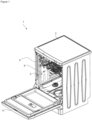
- Figure 1 -
- is the perspective view of the dishwasher.
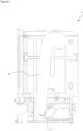
- Figure 2 -
- is the schematic view of the air duct.
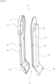
- Figure 3 -
- is the exploded view of the air guiding member.
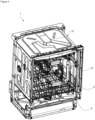
- Figure 4 -
- is the perspective view of the dishwasher and the air duct.
- The elements illustrated in the figures are numbered as follows.
- 1- Dishwasher
- 2- Body
- 3- Washing tub
- 4- Lower rack
- 5- Upper rack
- 6- Spraying member
- 7- Fan
- 8- Drying duct
- 9- Opening
- 10- Air guiding member
- 11- Control unit
- 12- Tank
- 13- Mouth portion
- 14- First shell
- 15- Air duct
- 16- Second shell
- 17- Sealing member
- 18- Claw
- 19- Housing
- 20- End portion
- 21- Guide
- 22- Stepped section
- The dishwasher (1) comprises a body (2); a washing tub (3) which is disposed in the body (2) and wherein the washing process is performed; at least one lower rack (4) and at least one upper rack (5) which are disposed in the washing tub (3) and whereon the kitchen items are placed; at least one spraying member (6) which sprays water onto the racks (4) to provide the performance of the washing process; a fan (7) which enables the moist air in the washing tub (3) to be sucked and discharged of the washing tub (3) during the drying process; a drying duct (8) which is disposed between the washing tub (3) and the body (2), which enables the moist air sucked from the washing tub (3) to condense, and one end of which opens into the washing tub (3); and an opening (9) which enables the air duct (8) to draw air from inside the washing tub (3). The kitchen items are placed onto the racks (4). The washing process is performed by spraying water by means of the spraying member (6). After the washing process, the drying step is started to quickly remove water droplets from the kitchen items. Therefore, the vapor density in the washing tub (3) is enabled to reduced. By means of the fan (7), the moist air is discharged from the washing tub (3), and the hot and humid air is guided through the drying duct (8). The drying duct (8) opens into the washing tub (3) through the opening (9).
- The dishwasher (1) of the present invention comprises an air guiding member (10) which is disposed in the washing tub (3), one end of which is connected to the drying duct (8) through the opening (9) and the other end extending towards the bottom of the washing tub (3). The air guiding member (10) is disposed in the washing tub (3). The hot air drawn from the washing tub (3) by means of the drying duct (8) is sent back into the washing tub (3) and delivered by means of the air guiding member (10). Thus, the air is cooled and controlled.
- In an embodiment of the present invention, the dishwasher (1) comprises a control unit (11) which ensures that the cold water taken from the mains is accumulated on the bottom of the washing tub (3) just before the drying step, and the air guiding member (10) which enables the hot air drawn from the washing tub (3) by means of the drying duct (8) to be delivered onto the cold water surface in the washing tub (3). After the washing step is completed, cold water is drawn from the mains into the washing tub (3) before the drying step begins. Thus, a cold surface is formed on the bottom of the washing tub (3). When the hot air drawn from the washing tub (3) is sent back into the washing tub (3), the hot air is enabled to hit the cold surface to be condensed. Thus, the temperature in the washing tub (3) is decreased and the drying process is performed in a shorter time.
- In an embodiment of the present invention, the dishwasher (1) comprises a tank (12) which is provided on the body (7), and the control unit (11) which enables the cold water in the washing tub (3) to be delivered into the tank (12) after the drying step is completed. Waste water is kept in the tank (12) disposed between the body (2) and the washing tub (3). The cold water taken into the washing tub (3) before the drying step heats up after being exposed to the hot air coming from the drying duct (8). When the drying step is completed, the heated clean water is delivered to the tank (12) to be used in the next cycle. Thus, less energy is consumed for heating the water in the next cycle. Consequently, the drying performance is improved and energy is saved.
- In an embodiment of the present invention, the dishwasher (1) comprises the air guiding member (10) having a first shell (14) with a mouth portion through which the air enters via the opening (9) and a second shell (16) which is joined with the first shell (14) to form an air duct (15) through which the air flows. The air guiding member (10) is formed by joining the first shell (14) and the second shell (16). Thus, the air guiding member (10) can be easily separated and cleaned by the user. When the first shell (14) and the second shell (16) are joined, the air duct (15) through which the hot air passes is formed therebetween. The mouth portion (13) arranged on the first shell (14) is seated onto the opening (9). Thus, the hot air is delivered from the air duct (15) to the air guiding member (10).
- In an embodiment of the present invention, the dishwasher (1) comprises the air guiding member (10) having a sealing member (17) which is provided on the mouth portion (13). Thus, the air flow between the drying duct (8) and the air guiding member (10) is prevented from being uncontrollably delivered into the washing tub (3). Moreover, the pressurized water sprayed by the spraying members is prevented from entering the drying duct (8).
- In an embodiment of the present invention, the dishwasher (1) comprises at least one claw (18) provided on the first shell (14) or the second shell (16) and at least one housing (19) provided on the first shell (14) or the second shell (16), and the first shell (14) and the second shell (16) which are joined by the engagement of the housings (19) and the claws (18). A claw (18) and a housing (19) is oppositely provided on the first shell (14) and the second shell (16). Thus, the first shell (14) and the second shell (16) are joined to form the air duct (15).
- In an embodiment of the present invention, the dishwasher (1) comprises the air guiding member (10) having an end portion (20) inclined towards the bottom of the washing tub (3) when mounted onto the washing tub (3). By means of the end portion (20) provided on the area of the air guiding member (10) close to the washing tub (3), the hot air is directly delivered onto the surface of the cold water accumulated on the bottom of the washing tub (3). Thus, the hot vapor suddenly hits the cold surface and condensation occurs very quickly. Consequently, the temperature of the air in the washing tub (3) is decreased.
- In an embodiment of the present invention, the dishwasher (1) comprises the air guiding member (10) which is detachably attached onto the lower rack (4). The air guiding member (10) can be attached onto the lower rack (4). Thus, the air guiding member (10) can be easily removed and cleaned by the user. When the lower rack (4) is pulled forward, the air guiding member (10) is separated from the opening (9), and while the lower rack (4) is in the washing tub (3), the air guiding member (10) aligns with the opening (9). The air guiding member (10) is positioned almost in the middle of the plate wires on the lower rack (4). Thus, the air guiding member (10) does not prevent the placement of kitchen items. Moreover, the air guiding member (10) can create a support surface for non-standard loads.
- In an embodiment of the present invention, the dishwasher (1) comprises the air guiding member (10) which can be attached to and detached from the lower rack (4) by sliding in the vertical plane by means of a guide (21) provided almost along its side edges. The air guiding member (10) can be attached to and detached from the lower rack (4) by sliding by means of the slides (21) provided on its side edges. Thus, the air guiding member (10) can be centered so as to be aligned with the opening (9).
- In an embodiment of the present invention, the dishwasher (1) comprises the air guiding member (1) having a stepped section (22) arranged on the second shell (16). By means of the stepped section (22) arranged on the second shell (16), the upper rack (5) can move more freely. Thus, the air guiding member (10) does not create an obstacle against load placement in the washing tub (3).
- By means of the present invention, a dishwasher (1) is realized, comprising an air guiding member (10), one end of which is connected to the drying duct (8) and the other end opening into the washing tub (3). Before the drying step begins, a cold surface is formed on the bottom of the washing tub (3) by means of the cold water drawn from the mains, and the hot air coming from the drying duct (8) is delivered onto the cold surface by means of the air guiding member (10) such that condensation is achieved. Thus, the temperature in the washing tub (3) is decreased and the drying performance is increased.
Claims (10)
- A dishwasher (1) comprising a body (2); a washing tub (3) which is disposed in the body (2) and wherein the washing process is performed; at least one lower rack (4) and at least one upper rack (5) which are disposed in the washing tub (3) and whereon the kitchen items are placed; at least one spraying member (6) which sprays water onto the racks (4) to provide the performance of the washing process; a fan (7) which enables the moist air in the washing tub (3) to be sucked and discharged of the washing tub (3) during the drying process; a drying duct (8) which is disposed between the washing tub (3) and the body (2), which enables the moist air sucked from the washing tub (3) to condense, and one end of which opens into the washing tub (3); and an opening (9) which enables the air duct (8) to draw air from inside the washing tub (3), characterized by an air guiding member (10) which is disposed in the washing tub (3), one end of which is connected to the drying duct (8) through the opening (9) and the other end extending towards the bottom of the washing tub (3).
- A dishwasher (1) as in Claim 1, characterized by a control unit (11) which ensures that the cold water taken from the mains is accumulated on the bottom of the washing tub (3) just before the drying step, and by the air guiding member (10) which enables the hot air drawn from the washing tub (3) by means of the drying duct (8) to be delivered onto the cold water surface in the washing tub (3).
- A dishwasher (1) as in Claim 2, characterized by comprises a tank (12) which is provided on the body (7), and by the control unit (11) which enables the cold water in the washing tub (3) to be delivered into the tank (12) after the drying step is completed.
- A dishwasher (1) as in any one of the above claims, characterized by the air guiding member (10) having a first shell (14) with a mouth portion through which the air enters via the opening (9) and a second shell (16) which is joined with the first shell (14) to form an air duct (15) through which the air flows.
- A dishwasher (1) as in Claim 4, characterized by the air guiding member (10) having a sealing member (17) which is provided on the mouth portion (13).
- A dishwasher (1) as in Claim 4, characterized by at least one claw (18) provided on the first shell (14) or the second shell (16) and at least one housing (19) provided on the first shell (14) or the second shell (16), and the first shell (14) and the second shell (16) which are joined by the engagement of the housings (19) and the claws (18).
- A dishwasher (1) as in any one of the above claims, characterized by the air guiding member (10) having an end portion (20) inclined towards the bottom of the washing tub (3) when mounted onto the washing tub (3).
- A dishwasher (1) as in any one of the above claims, characterized by the air guiding member (10) which is detachably attached onto the lower rack (4).
- A dishwasher (1) as in Claim 8, characterized by the air guiding member (10) which can be attached to and detached from the lower rack (4) by sliding in the vertical plane by means of a guide (21) provided almost along its side edges.
- A dishwasher (1) as in any one of Claims 4 to 9, characterized by the air guiding member (1) having a stepped section (22) arranged on the second shell (16).
Applications Claiming Priority (1)
| Application Number | Priority Date | Filing Date | Title |
|---|---|---|---|
| TR202305137 | 2023-05-09 |
Publications (2)
| Publication Number | Publication Date |
|---|---|
| EP4461194A1 true EP4461194A1 (en) | 2024-11-13 |
| EP4461194B1 EP4461194B1 (en) | 2026-02-18 |
Family
ID=90123145
Family Applications (1)
| Application Number | Title | Priority Date | Filing Date |
|---|---|---|---|
| EP24160460.2A Active EP4461194B1 (en) | 2023-05-09 | 2024-02-29 | A dishwasher with improved drying performance |
Country Status (1)
| Country | Link |
|---|---|
| EP (1) | EP4461194B1 (en) |
Citations (4)
| Publication number | Priority date | Publication date | Assignee | Title |
|---|---|---|---|---|
| DE2440422A1 (en) * | 1974-08-23 | 1976-03-04 | Euro Hausgeraete Gmbh | Drying method for programmed dish washing machine - uses heating air circulated inside, then mixed with cold air after final wash |
| DE19946563A1 (en) * | 1999-09-29 | 2001-04-12 | Aeg Hausgeraete Gmbh | Dishwasher with a washing container |
| WO2014180648A1 (en) | 2013-05-06 | 2014-11-13 | Arcelik Anonim Sirketi | A dishwasher with improved drying performance |
| US20220125276A1 (en) * | 2020-10-22 | 2022-04-28 | Lg Electronics Inc. | Dishwasher |
-
2024
- 2024-02-29 EP EP24160460.2A patent/EP4461194B1/en active Active
Patent Citations (4)
| Publication number | Priority date | Publication date | Assignee | Title |
|---|---|---|---|---|
| DE2440422A1 (en) * | 1974-08-23 | 1976-03-04 | Euro Hausgeraete Gmbh | Drying method for programmed dish washing machine - uses heating air circulated inside, then mixed with cold air after final wash |
| DE19946563A1 (en) * | 1999-09-29 | 2001-04-12 | Aeg Hausgeraete Gmbh | Dishwasher with a washing container |
| WO2014180648A1 (en) | 2013-05-06 | 2014-11-13 | Arcelik Anonim Sirketi | A dishwasher with improved drying performance |
| US20220125276A1 (en) * | 2020-10-22 | 2022-04-28 | Lg Electronics Inc. | Dishwasher |
Also Published As
| Publication number | Publication date |
|---|---|
| EP4461194B1 (en) | 2026-02-18 |
Similar Documents
| Publication | Publication Date | Title |
|---|---|---|
| EP1881873B1 (en) | Commercial dishwasher | |
| KR102124926B1 (en) | Air blower and dish washer having the same | |
| US10980395B2 (en) | Dishwasher | |
| WO2005019735A1 (en) | Heating cooker | |
| KR101122830B1 (en) | A condensing apparatus of a dish washer | |
| US11134827B2 (en) | Dishwasher | |
| EP3524127B1 (en) | Dishwasher | |
| KR100630974B1 (en) | dish washer | |
| EP4461194B1 (en) | A dishwasher with improved drying performance | |
| KR101122837B1 (en) | A condensing apparatus of a dish washer | |
| US20250017439A1 (en) | Commercial dishwasher with a drying module, method for operating such a dishwasher, and drying module for a dishwasher | |
| JPH0260622A (en) | Dish washer/drier | |
| JPH08215127A (en) | Dishwasher | |
| KR100211526B1 (en) | Air circulation dish dryer | |
| JP2002000533A (en) | Dishwasher | |
| KR20250038986A (en) | Dish washer | |
| KR101178688B1 (en) | Condensing system of dish washer | |
| TR2023005137A2 (en) | A DISHWASHER WITH IMPROVED DRYING PERFORMANCE | |
| KR20260056649A (en) | dish dryer | |
| KR20070007547A (en) | Condenser unit of the dishwasher | |
| KR20070026268A (en) | dish washer | |
| KR200152801Y1 (en) | Dishwasher | |
| JPH02124125A (en) | dishwasher | |
| JPH05220081A (en) | Dish washer |
Legal Events
| Date | Code | Title | Description |
|---|---|---|---|
| PUAI | Public reference made under article 153(3) epc to a published international application that has entered the european phase |
Free format text: ORIGINAL CODE: 0009012 |
|
| STAA | Information on the status of an ep patent application or granted ep patent |
Free format text: STATUS: REQUEST FOR EXAMINATION WAS MADE |
|
| 17P | Request for examination filed |
Effective date: 20240229 |
|
| AK | Designated contracting states |
Kind code of ref document: A1 Designated state(s): AL AT BE BG CH CY CZ DE DK EE ES FI FR GB GR HR HU IE IS IT LI LT LU LV MC ME MK MT NL NO PL PT RO RS SE SI SK SM TR |
|
| GRAP | Despatch of communication of intention to grant a patent |
Free format text: ORIGINAL CODE: EPIDOSNIGR1 |
|
| STAA | Information on the status of an ep patent application or granted ep patent |
Free format text: STATUS: GRANT OF PATENT IS INTENDED |
|
| INTG | Intention to grant announced |
Effective date: 20251023 |
|
| GRAS | Grant fee paid |
Free format text: ORIGINAL CODE: EPIDOSNIGR3 |
|
| GRAA | (expected) grant |
Free format text: ORIGINAL CODE: 0009210 |
|
| STAA | Information on the status of an ep patent application or granted ep patent |
Free format text: STATUS: THE PATENT HAS BEEN GRANTED |
|
| AK | Designated contracting states |
Kind code of ref document: B1 Designated state(s): AL AT BE BG CH CY CZ DE DK EE ES FI FR GB GR HR HU IE IS IT LI LT LU LV MC ME MK MT NL NO PL PT RO RS SE SI SK SM TR |
|
| REG | Reference to a national code |
Ref country code: CH Ref legal event code: F10 Free format text: ST27 STATUS EVENT CODE: U-0-0-F10-F00 (AS PROVIDED BY THE NATIONAL OFFICE) Effective date: 20260218 Ref country code: GB Ref legal event code: FG4D |
|
| REG | Reference to a national code |
Ref country code: DE Ref legal event code: R096 Ref document number: 602024002551 Country of ref document: DE |
|
| REG | Reference to a national code |
Ref country code: IE Ref legal event code: FG4D |
|
| REG | Reference to a national code |
Ref country code: NL Ref legal event code: MP Effective date: 20260218 |
|
| PG25 | Lapsed in a contracting state [announced via postgrant information from national office to epo] |
Ref country code: RS Free format text: LAPSE BECAUSE OF FAILURE TO SUBMIT A TRANSLATION OF THE DESCRIPTION OR TO PAY THE FEE WITHIN THE PRESCRIBED TIME-LIMIT Effective date: 20260518 |
|
| PG25 | Lapsed in a contracting state [announced via postgrant information from national office to epo] |
Ref country code: ES Free format text: LAPSE BECAUSE OF FAILURE TO SUBMIT A TRANSLATION OF THE DESCRIPTION OR TO PAY THE FEE WITHIN THE PRESCRIBED TIME-LIMIT Effective date: 20260218 |
|
| PG25 | Lapsed in a contracting state [announced via postgrant information from national office to epo] |
Ref country code: PL Free format text: LAPSE BECAUSE OF FAILURE TO SUBMIT A TRANSLATION OF THE DESCRIPTION OR TO PAY THE FEE WITHIN THE PRESCRIBED TIME-LIMIT Effective date: 20260218 |
|
| PG25 | Lapsed in a contracting state [announced via postgrant information from national office to epo] |
Ref country code: GR Free format text: LAPSE BECAUSE OF FAILURE TO SUBMIT A TRANSLATION OF THE DESCRIPTION OR TO PAY THE FEE WITHIN THE PRESCRIBED TIME-LIMIT Effective date: 20260519 |
|
| REG | Reference to a national code |
Ref country code: LT Ref legal event code: MG9D |
|
| PG25 | Lapsed in a contracting state [announced via postgrant information from national office to epo] |
Ref country code: LT Free format text: LAPSE BECAUSE OF FAILURE TO SUBMIT A TRANSLATION OF THE DESCRIPTION OR TO PAY THE FEE WITHIN THE PRESCRIBED TIME-LIMIT Effective date: 20260218 |
|
| PGFP | Annual fee paid to national office [announced via postgrant information from national office to epo] |
Ref country code: DE Payment date: 20260422 Year of fee payment: 3 |
|
| PG25 | Lapsed in a contracting state [announced via postgrant information from national office to epo] |
Ref country code: NO Free format text: LAPSE BECAUSE OF FAILURE TO SUBMIT A TRANSLATION OF THE DESCRIPTION OR TO PAY THE FEE WITHIN THE PRESCRIBED TIME-LIMIT Effective date: 20260518 |
|
| PG25 | Lapsed in a contracting state [announced via postgrant information from national office to epo] |
Ref country code: FI Free format text: LAPSE BECAUSE OF FAILURE TO SUBMIT A TRANSLATION OF THE DESCRIPTION OR TO PAY THE FEE WITHIN THE PRESCRIBED TIME-LIMIT Effective date: 20260218 Ref country code: AT Free format text: LAPSE BECAUSE OF FAILURE TO SUBMIT A TRANSLATION OF THE DESCRIPTION OR TO PAY THE FEE WITHIN THE PRESCRIBED TIME-LIMIT Effective date: 20260218 Ref country code: SE Free format text: LAPSE BECAUSE OF FAILURE TO SUBMIT A TRANSLATION OF THE DESCRIPTION OR TO PAY THE FEE WITHIN THE PRESCRIBED TIME-LIMIT Effective date: 20260218 |
|
| REG | Reference to a national code |
Ref country code: AT Ref legal event code: MK05 Ref document number: 1887096 Country of ref document: AT Kind code of ref document: T Effective date: 20260218 |
|
| PG25 | Lapsed in a contracting state [announced via postgrant information from national office to epo] |
Ref country code: HR Free format text: LAPSE BECAUSE OF FAILURE TO SUBMIT A TRANSLATION OF THE DESCRIPTION OR TO PAY THE FEE WITHIN THE PRESCRIBED TIME-LIMIT Effective date: 20260218 |
|
| PG25 | Lapsed in a contracting state [announced via postgrant information from national office to epo] |
Ref country code: PT Free format text: LAPSE BECAUSE OF FAILURE TO SUBMIT A TRANSLATION OF THE DESCRIPTION OR TO PAY THE FEE WITHIN THE PRESCRIBED TIME-LIMIT Effective date: 20260618 Ref country code: IS Free format text: LAPSE BECAUSE OF FAILURE TO SUBMIT A TRANSLATION OF THE DESCRIPTION OR TO PAY THE FEE WITHIN THE PRESCRIBED TIME-LIMIT Effective date: 20260618 |
|
| PG25 | Lapsed in a contracting state [announced via postgrant information from national office to epo] |
Ref country code: NL Free format text: LAPSE BECAUSE OF FAILURE TO SUBMIT A TRANSLATION OF THE DESCRIPTION OR TO PAY THE FEE WITHIN THE PRESCRIBED TIME-LIMIT Effective date: 20260218 |
|
| PGFP | Annual fee paid to national office [announced via postgrant information from national office to epo] |
Ref country code: TR Payment date: 20260415 Year of fee payment: 3 |
|
| PG25 | Lapsed in a contracting state [announced via postgrant information from national office to epo] |
Ref country code: LV Free format text: LAPSE BECAUSE OF FAILURE TO SUBMIT A TRANSLATION OF THE DESCRIPTION OR TO PAY THE FEE WITHIN THE PRESCRIBED TIME-LIMIT Effective date: 20260218 |
|
| PG25 | Lapsed in a contracting state [announced via postgrant information from national office to epo] |
Ref country code: BG Free format text: LAPSE BECAUSE OF FAILURE TO SUBMIT A TRANSLATION OF THE DESCRIPTION OR TO PAY THE FEE WITHIN THE PRESCRIBED TIME-LIMIT Effective date: 20260218 |