EP4461192A1 - A dishwasher comprising a heat pump - Google Patents
A dishwasher comprising a heat pump Download PDFInfo
- Publication number
- EP4461192A1 EP4461192A1 EP24160463.6A EP24160463A EP4461192A1 EP 4461192 A1 EP4461192 A1 EP 4461192A1 EP 24160463 A EP24160463 A EP 24160463A EP 4461192 A1 EP4461192 A1 EP 4461192A1
- Authority
- EP
- European Patent Office
- Prior art keywords
- heat exchanger
- separator
- dishwasher
- water
- heat
- Prior art date
- Legal status (The legal status is an assumption and is not a legal conclusion. Google has not performed a legal analysis and makes no representation as to the accuracy of the status listed.)
- Granted
Links
Images


Classifications
-
- A—HUMAN NECESSITIES
- A47—FURNITURE; DOMESTIC ARTICLES OR APPLIANCES; COFFEE MILLS; SPICE MILLS; SUCTION CLEANERS IN GENERAL
- A47L—DOMESTIC WASHING OR CLEANING; SUCTION CLEANERS IN GENERAL
- A47L15/00—Washing or rinsing machines for crockery or tableware
- A47L15/42—Details
- A47L15/4291—Recovery arrangements, e.g. for the recovery of energy or water
-
- A—HUMAN NECESSITIES
- A47—FURNITURE; DOMESTIC ARTICLES OR APPLIANCES; COFFEE MILLS; SPICE MILLS; SUCTION CLEANERS IN GENERAL
- A47L—DOMESTIC WASHING OR CLEANING; SUCTION CLEANERS IN GENERAL
- A47L15/00—Washing or rinsing machines for crockery or tableware
- A47L15/42—Details
- A47L15/4285—Water-heater arrangements
-
- Y—GENERAL TAGGING OF NEW TECHNOLOGICAL DEVELOPMENTS; GENERAL TAGGING OF CROSS-SECTIONAL TECHNOLOGIES SPANNING OVER SEVERAL SECTIONS OF THE IPC; TECHNICAL SUBJECTS COVERED BY FORMER USPC CROSS-REFERENCE ART COLLECTIONS [XRACs] AND DIGESTS
- Y02—TECHNOLOGIES OR APPLICATIONS FOR MITIGATION OR ADAPTATION AGAINST CLIMATE CHANGE
- Y02B—CLIMATE CHANGE MITIGATION TECHNOLOGIES RELATED TO BUILDINGS, e.g. HOUSING, HOUSE APPLIANCES OR RELATED END-USER APPLICATIONS
- Y02B30/00—Energy efficient heating, ventilation or air conditioning [HVAC]
- Y02B30/52—Heat recovery pumps, i.e. heat pump based systems or units able to transfer the thermal energy from one area of the premises or part of the facilities to a different one, improving the overall efficiency
Definitions
- the present invention relates to a dishwasher comprising a heat pump.
- heat pumps are used for decreasing the energy consumption and improve the drying performance.
- the heat pump is composed of the compressor, the condenser, the throttle valve and the evaporator elements.
- the components of the heat pump are connected via a pipe line and the heat pump operates by means of the cycle fluid in the line.
- the condenser is a tube bundle having a hot surface and enables the water to be heated by being positioned in the washing water of the dishwasher.
- the evaporator has a cold surface and is positioned so as to contact the ambient air. The evaporator absorbs heat from the environment and provides the heat transfer to the compressor and the condenser.
- the compressor for heating the water, the compressor is operated to enable the condenser to heat the water, and the evaporator is enabled to absorb heat from the environment to support the condenser which heats the water.
- the compressor pressurizes and sends the cycle fluid to the condenser.
- the cycle fluid passes through the condenser and reaches the evaporator. After the evaporator, the cycle fluid returns to the compressor.
- the cycle is completed.
- the water heated by the condenser is transmitted to the multiport valve. According to the algorithm-dependent position of the multiport valve, the water is transmitted to the relevant spray arm through a water line to be sprayed into the dishwasher.
- the water is discharged from the sump by means of the discharge pump.
- temperature balance should be established. Therefore, fans are used to efficiently suck the ambient air and direct the same to the evaporator.
- two fans usually positioned side by side are used. However, the operation of the fans may cause adverse effects due to the air flows . As one fan creates a flow in the opposite direction to the flow of the other fan, the air is prevented from being sucked, which decreases the efficiency of the heat pump.
- a dishwasher comprising a heat pump having an air guiding duct.
- the aim of the present invention is the realization of a dishwasher comprising a heat pump with increased efficiency.
- the dishwasher realized in order to attain the aim of the present invention, explicated in the first claim and the respective claims thereof comprises a body; a washing tub which is disposed in the body and wherein the dishes to be washed are placed; a sump which is disposed under the washing tub and wherein the washing water is collected; at least one spraying member which ensures the performance of the washing process; a multiport valve which enables the water to be transmitted to the spraying member; and a heat pump which is disposed between the washing tub and the body.
- the heat pump comprises a first heat exchanger which draws heat from the environment and enables the water to be used in the washing step to be heated; a plurality of fans which draw the air from the environment to be delivered to the first heat exchanger; a second heat exchanger which transfers the heat received from the first heat exchanger to the washing tub; a capillary tube which is disposed between the first heat exchanger and the second heat exchanger; and a compressor which realizes the refrigerant cycle between the first heat exchanger and the second heat exchanger.
- the dishwasher of the present invention comprises a separator which is positioned between the fans and which extends towards the sump. By means of the separator, the air flows of the fans are separated from each other, thus increasing the amount of air drawn from the environment. Since the amount of air flow delivered to the first heat exchanger increases, the efficiency of the heat pump is improved.
- the dishwasher comprises the separator in the form of a plate.
- the separator By means of the plate form of the separator, the air flow between the fans is prevented, and the separator provides thermal insulation by extending towards the sump and forming partitions.
- the dishwasher comprises the separator which has a hollow volume.
- the separator which has a hollow volume.
- the dishwasher comprises the separator whereon the capillary tube is disposed.
- the capillary tubes are fixed onto the separator, preventing noise generation.
- the dishwasher comprises the separator having a plurality of air ducts arranged thereon.
- the separator having a plurality of air ducts arranged thereon.
- the dishwasher comprises a plurality of heat conducting members which are disposed between the sump and the separator.
- heat transfer is provided between the sump and the separator, and the heat of the hot water collected in the sump is enabled to be transferred to the separator. Consequently, the temperature of the air transferred to the first heat exchanger increases, improving the efficiency.
- the dishwasher comprises at least one water duct which is disposed between the sump and the separator.
- the separator can be used as a tank connected to the sump. Consequently, the amount of water stored is increased, improving the efficiency thanks to the accumulation of hot water.
- a dishwasher comprising a heat pump having a separator which ensures the separation of the air flows generated by the fans.
- the dishwasher (1) comprises a body (2); a washing tub (3) which is disposed in the body (2) and wherein the washing process is performed; a sump (4) which is disposed under the washing tub (3) and wherein the water flowing down from the washing tub (3) is collected; at least one spraying member (5) which sprays water onto the kitchen items placed into the washing tub (3); a heat pump (11) which is arranged under the washing tub (3) and which has a first heat exchanger (6) which draws heat from the environment and enables the water to be used in the washing step to be heated, a plurality of fans (7) which draw the air from the environment to be delivered to the first heat exchanger (6), a second heat exchanger (8) which transfers the heat received from the first heat exchanger (6) to the washing water, a capillary tube (9) which is disposed between the first heat exchanger (6) and the second heat exchanger (8), a compressor (10) which is in fluid communication with the first the first heat exchanger (6) and the second heat exchanger (8) and which provides the refrigerant cycle; and
- the water is heated by the heat pump (11) positioned at the lower part of the dishwasher (1).
- the heat pump (11) is composed of the compressor (10), the second heat exchanger (8), the capillary tubes (9) and the first heat exchanger (6) which is of the air-to-air type.
- the compressor (10) pressurizes the refrigerant and delivers the same to the second heat exchanger (8).
- the pressure and the temperature of the refrigerant increase.
- the pipes of the second heat exchanger (8) are heated.
- the refrigerant leaving the second heat exchanger (8) is directed to the capillary tubes (9).
- the refrigerant leaving the capillary tubes (9) is directed to the first heat exchanger (6).
- the first heat exchanger (6) is of the air-to-air type.
- the first heat exchanger (6) is disposed in a closed volume between the fans (7) on one side and the outer environment on the other side.
- the air drawn from the lower section of the casing by means of the fans (7) is directed onto the first heat exchanger (6).
- the air passed over the first heat exchanger (6) is discharged from the rear side of the dishwasher (1).
- the dishwasher (1) of the present invention comprises a separator (13) which passes between the fans (7) to extend towards the sump (4).
- the separator (13) is positioned between the two fans (7) and extends towards the sump (4).
- the separator (13) disposed between the fans (7) the air flows of the fans (7) are completely separated from each other.
- the fans (7) are positioned side by side, the air flows do not affect each other.
- ease of placement is ensured.
- the efficiency of the heat pump (11) is improved.
- the dishwasher (1) comprises the separator (13) in the form of a plate.
- the separator (13) in the form of a plate extends towards the sump (4) between the fans (7). Thus, the air flows of the fans (7) are not mixed with each other.
- the dishwasher (1) comprises the separator (13) which has a hollow volume.
- the separator (13) By means of the tank form of the separator (13), water can be collected therein.
- the collected water can be used in various cycles.
- thermal gain is achieved by storing hot water and the efficiency of the heat pump (11) is improved.
- the dishwasher (1) comprises the separator (13) whereon the capillary tube (9) is disposed.
- the capillary tubes (9) are fixed onto the separator (13).
- the capillary tubes (9) affected by the vibration occurring during the operation of the heat pump (11) are prevented from generating noise. Consequently, a rigid structure is obtained.
- the dishwasher (1) comprises the separator (3) which provides sound insulation by means of a plurality of air ducts (14) arranged thereon.
- the separator (13) can be used as an insulation member.
- the micro air ducts (14) ensure the sound and temperature insulation of the separator (13) to be improved.
- the dishwasher (1) comprises a plurality of heat conducting members (15) which are disposed between the sump (4) and the separator (13) and which provide heat transfer. Thanks to the heat conducting members (15), one end of which is positioned on the sump (4) and the other end on the separator (13), the heat generated by the hot water collected in the sump (4) is transmitted to the separator (13). Thus, the temperature of the air delivered to the first heat exchanger (6) increases, improving the efficiency of the heat pump (11).
- the dishwasher (1) comprises at least one water duct (16) which is disposed between the sump (4) and the separator (13) and which enables the water collected in the sump (4) to be delivered to the separator (13).
- the separator (13) is used as an additional tank.
- the separator (13) is enabled to be heated with hot water, improving the efficiency of the heat pump (11).
- the dishwasher (1) may comprise a separate third heat exchanger.
- Said third heat exchanger can also be an extension of the second heat exchanger (8).
- the dishwasher (1) may comprise the third heat exchanger which is a water line.
- the water line ensuring the flow of waste hot water can be used as the third heat exchanger.
- the dishwasher (1) may comprise the third heat exchanger which is an electric heater.
- the defrost effect is achieved.
- a dishwasher is realized, wherein by means of a separator (13) disposed between the two fans (7) and extending towards the sump (4), the air flows sucked by the fans (7) are enabled to be separated from each other and the efficiency of the pump (11) is improved. Consequently, thermal and sound insulation is provided and the heat pump (11) is enabled to be operated at optimum efficiency.
Landscapes
- Washing And Drying Of Tableware (AREA)
Abstract
Description
- The present invention relates to a dishwasher comprising a heat pump.
- In dishwashers, heat pumps are used for decreasing the energy consumption and improve the drying performance. In heat pump dishwashers, the heat pump is composed of the compressor, the condenser, the throttle valve and the evaporator elements. The components of the heat pump are connected via a pipe line and the heat pump operates by means of the cycle fluid in the line. The condenser is a tube bundle having a hot surface and enables the water to be heated by being positioned in the washing water of the dishwasher. The evaporator has a cold surface and is positioned so as to contact the ambient air. The evaporator absorbs heat from the environment and provides the heat transfer to the compressor and the condenser. In this type of heat pump systems, for heating the water, the compressor is operated to enable the condenser to heat the water, and the evaporator is enabled to absorb heat from the environment to support the condenser which heats the water. The compressor pressurizes and sends the cycle fluid to the condenser. The cycle fluid passes through the condenser and reaches the evaporator. After the evaporator, the cycle fluid returns to the compressor. By sending the fluid received by the compressor to the condenser again, the cycle is completed. The water heated by the condenser is transmitted to the multiport valve. According to the algorithm-dependent position of the multiport valve, the water is transmitted to the relevant spray arm through a water line to be sprayed into the dishwasher. In the related discharge step, the water is discharged from the sump by means of the discharge pump. In order to ensure the efficient operation of the heat pump, temperature balance should be established. Therefore, fans are used to efficiently suck the ambient air and direct the same to the evaporator. In the dishwasher, generally, two fans usually positioned side by side are used. However, the operation of the fans may cause adverse effects due to the air flows . As one fan creates a flow in the opposite direction to the flow of the other fan, the air is prevented from being sucked, which decreases the efficiency of the heat pump.
- In the state of the art European Patent No.
EP3427628 , a dishwasher is disclosed, comprising a heat pump having an air guiding duct. - The aim of the present invention is the realization of a dishwasher comprising a heat pump with increased efficiency.
- The dishwasher realized in order to attain the aim of the present invention, explicated in the first claim and the respective claims thereof comprises a body; a washing tub which is disposed in the body and wherein the dishes to be washed are placed; a sump which is disposed under the washing tub and wherein the washing water is collected; at least one spraying member which ensures the performance of the washing process; a multiport valve which enables the water to be transmitted to the spraying member; and a heat pump which is disposed between the washing tub and the body. The heat pump comprises a first heat exchanger which draws heat from the environment and enables the water to be used in the washing step to be heated; a plurality of fans which draw the air from the environment to be delivered to the first heat exchanger; a second heat exchanger which transfers the heat received from the first heat exchanger to the washing tub; a capillary tube which is disposed between the first heat exchanger and the second heat exchanger; and a compressor which realizes the refrigerant cycle between the first heat exchanger and the second heat exchanger.
- The dishwasher of the present invention comprises a separator which is positioned between the fans and which extends towards the sump. By means of the separator, the air flows of the fans are separated from each other, thus increasing the amount of air drawn from the environment. Since the amount of air flow delivered to the first heat exchanger increases, the efficiency of the heat pump is improved.
- In an embodiment of the present invention, the dishwasher comprises the separator in the form of a plate. By means of the plate form of the separator, the air flow between the fans is prevented, and the separator provides thermal insulation by extending towards the sump and forming partitions.
- In an embodiment of the present invention, the dishwasher comprises the separator which has a hollow volume. Thus, it becomes possible to store water in the separator, and the environment of the heat pump is also heated by means of the heated water. Thus, the efficiency is improved.
- In an embodiment of the present invention, the dishwasher comprises the separator whereon the capillary tube is disposed. Thus, the capillary tubes are fixed onto the separator, preventing noise generation.
- In an embodiment of the present invention, the dishwasher comprises the separator having a plurality of air ducts arranged thereon. By means of the micro air ducts arranged on the separator, gaps are formed and sound insulation is provided.
- In an embodiment of the present invention, the dishwasher comprises a plurality of heat conducting members which are disposed between the sump and the separator. Thus, heat transfer is provided between the sump and the separator, and the heat of the hot water collected in the sump is enabled to be transferred to the separator. Consequently, the temperature of the air transferred to the first heat exchanger increases, improving the efficiency.
- In an embodiment of the present invention, the dishwasher comprises at least one water duct which is disposed between the sump and the separator. Thus, the separator can be used as a tank connected to the sump. Consequently, the amount of water stored is increased, improving the efficiency thanks to the accumulation of hot water.
- By means of the present invention, a dishwasher is realized, comprising a heat pump having a separator which ensures the separation of the air flows generated by the fans.
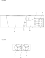
- A dishwasher realized in order to attain the aim of the present invention is illustrated in the attached figures, where:
-
Figure 1 - is the schematic view of the dishwasher. -
Figure 2 - is the schematic view of the separator and the air ducts. -
Figure 3 - is the schematic view of the separator, the capillary tube and the heat conducting member. -
Figure 4 - is the schematic view of the separator and the water ducts. -
Figure 5 - is the schematic view of the fan and the separator. - The elements illustrated in the figures are numbered as follows.
- 1- Dishwasher
- 2- Body
- 3- Washing tub
- 4- Sump
- 5- Spraying member
- 6- First heat exchanger
- 7- Fan
- 8- Second heat exchanger
- 9- Capillary tube
- 10- Compressor
- 11- Heat pump
- 12- Multiport valve
- 13- Separator
- 14- Air duct
- 15- Heat conducting member
- 16- Water duct
- The dishwasher (1) comprises a body (2); a washing tub (3) which is disposed in the body (2) and wherein the washing process is performed; a sump (4) which is disposed under the washing tub (3) and wherein the water flowing down from the washing tub (3) is collected; at least one spraying member (5) which sprays water onto the kitchen items placed into the washing tub (3); a heat pump (11) which is arranged under the washing tub (3) and which has a first heat exchanger (6) which draws heat from the environment and enables the water to be used in the washing step to be heated, a plurality of fans (7) which draw the air from the environment to be delivered to the first heat exchanger (6), a second heat exchanger (8) which transfers the heat received from the first heat exchanger (6) to the washing water, a capillary tube (9) which is disposed between the first heat exchanger (6) and the second heat exchanger (8), a compressor (10) which is in fluid communication with the first the first heat exchanger (6) and the second heat exchanger (8) and which provides the refrigerant cycle; and a multiport valve (12) which enables the heated water to be delivered to the spraying members (5). The water is heated by the heat pump (11) positioned at the lower part of the dishwasher (1). The heat pump (11) is composed of the compressor (10), the second heat exchanger (8), the capillary tubes (9) and the first heat exchanger (6) which is of the air-to-air type. The compressor (10) pressurizes the refrigerant and delivers the same to the second heat exchanger (8). Upon being pressurized by the compressor (10), the pressure and the temperature of the refrigerant increase. Thus, the pipes of the second heat exchanger (8) are heated. As a result, the water in contact with the pipes of the second heat exchanger (8) is heated. The refrigerant leaving the second heat exchanger (8) is directed to the capillary tubes (9). Consequently, a significant decrease in pressure and therefore temperature thereof is observed The refrigerant leaving the capillary tubes (9) is directed to the first heat exchanger (6). The first heat exchanger (6) is of the air-to-air type. The first heat exchanger (6) is disposed in a closed volume between the fans (7) on one side and the outer environment on the other side. The air drawn from the lower section of the casing by means of the fans (7) is directed onto the first heat exchanger (6). The air passed over the first heat exchanger (6) is discharged from the rear side of the dishwasher (1).
- The dishwasher (1) of the present invention comprises a separator (13) which passes between the fans (7) to extend towards the sump (4). The separator (13) is positioned between the two fans (7) and extends towards the sump (4). By means of the separator (13) disposed between the fans (7), the air flows of the fans (7) are completely separated from each other. Thus, although the fans (7) are positioned side by side, the air flows do not affect each other. Thus, ease of placement is ensured. Moreover, since the amount of sucked air increases, the efficiency of the heat pump (11) is improved.
- In an embodiment of the present invention, the dishwasher (1) comprises the separator (13) in the form of a plate. The separator (13) in the form of a plate extends towards the sump (4) between the fans (7). Thus, the air flows of the fans (7) are not mixed with each other.
- In an embodiment of the present invention, the dishwasher (1) comprises the separator (13) which has a hollow volume. By means of the tank form of the separator (13), water can be collected therein. The collected water can be used in various cycles. Moreover, thermal gain is achieved by storing hot water and the efficiency of the heat pump (11) is improved.
- In an embodiment of the present invention, the dishwasher (1) comprises the separator (13) whereon the capillary tube (9) is disposed. The capillary tubes (9) are fixed onto the separator (13). Thus, the capillary tubes (9) affected by the vibration occurring during the operation of the heat pump (11) are prevented from generating noise. Consequently, a rigid structure is obtained.
- In an embodiment of the present invention, the dishwasher (1) comprises the separator (3) which provides sound insulation by means of a plurality of air ducts (14) arranged thereon. By means of the air ducts (14) arranged on the separator (13), the separator (13) can be used as an insulation member. The micro air ducts (14) ensure the sound and temperature insulation of the separator (13) to be improved.
- In an embodiment of the present invention, the dishwasher (1) comprises a plurality of heat conducting members (15) which are disposed between the sump (4) and the separator (13) and which provide heat transfer. Thanks to the heat conducting members (15), one end of which is positioned on the sump (4) and the other end on the separator (13), the heat generated by the hot water collected in the sump (4) is transmitted to the separator (13). Thus, the temperature of the air delivered to the first heat exchanger (6) increases, improving the efficiency of the heat pump (11).
- In an embodiment of the present invention, the dishwasher (1) comprises at least one water duct (16) which is disposed between the sump (4) and the separator (13) and which enables the water collected in the sump (4) to be delivered to the separator (13). By means of the water duct (16) disposed between the sump (4) and the separator (13), the separator (13) is used as an additional tank. Thus, the amount of water collected is increased, providing savings in water consumption. Moreover, the separator (13) is enabled to be heated with hot water, improving the efficiency of the heat pump (11).
- In an alternative embodiment of the present invention, the dishwasher (1) may comprise a separate third heat exchanger. Said third heat exchanger can also be an extension of the second heat exchanger (8).
- In an alternative embodiment of the present invention, the dishwasher (1) may comprise the third heat exchanger which is a water line. Preferably, the water line ensuring the flow of waste hot water can be used as the third heat exchanger.
- In an alternative embodiment of the present invention, the dishwasher (1) may comprise the third heat exchanger which is an electric heater. Thus, the defrost effect is achieved.
- By means of the present invention, a dishwasher is realized, wherein by means of a separator (13) disposed between the two fans (7) and extending towards the sump (4), the air flows sucked by the fans (7) are enabled to be separated from each other and the efficiency of the pump (11) is improved. Consequently, thermal and sound insulation is provided and the heat pump (11) is enabled to be operated at optimum efficiency.
Claims (7)
- A dishwasher (1) comprising a body (2); a washing tub (3) which is disposed in the body (2) and wherein the washing process is performed; a sump (4) which is disposed under the washing tub (3) and wherein the water flowing down from the washing tub (3) is collected; at least one spraying member (5) which sprays water onto the kitchen items placed into the washing tub (3); a heat pump (11) which is arranged under the washing tub (3) and which has a first heat exchanger (6) which draws heat from the environment and enables the water to be used in the washing step to be heated, a plurality of fans (7) which draw the air from the environment to be delivered to the first heat exchanger (6), a second heat exchanger (8) which transfers the heat received from the first heat exchanger (6) to the washing water, a capillary tube (9) which is disposed between the first heat exchanger (6) and the second heat exchanger (8), a compressor (10) which is in fluid communication with the first the first heat exchanger (6) and the second heat exchanger (8) and which provides the refrigerant cycle; and a multiport valve (12) which enables the heated water to be delivered to the spraying members (5), characterized by a separator (13) which is disposed on the heat pump (11) and which passes between the fans (7) to extend towards the sump (4).
- A dishwasher (1) as in Claim 1, characterized by the separator (13) in the form of a plate.
- A dishwasher (1) as in Claim 1, characterized by the separator (13) which has a hollow volume.
- A dishwasher (1) as in any one of the above claims, characterized by the separator (13) whereon the capillary tube (9) is disposed.
- A dishwasher (1) as in any one of the above claims, characterized by the separator (3) which provides sound insulation by means of a plurality of air ducts (14) arranged thereon.
- A dishwasher (1) as in any one of the above claims, characterized by a plurality of heat conducting members (15) which are disposed between the sump (4) and the separator (13) and which provide heat transfer.
- A dishwasher (1) as in any one of Claim 3 to Claim 6, characterized by at least one water duct (16) which is disposed between the sump (4) and the separator (13) and which enables the water collected in the sump (4) to be delivered to the separator (13).
Applications Claiming Priority (1)
| Application Number | Priority Date | Filing Date | Title |
|---|---|---|---|
| TR202305197 | 2023-05-10 |
Publications (2)
| Publication Number | Publication Date |
|---|---|
| EP4461192A1 true EP4461192A1 (en) | 2024-11-13 |
| EP4461192B1 EP4461192B1 (en) | 2025-12-10 |
Family
ID=90123384
Family Applications (1)
| Application Number | Title | Priority Date | Filing Date |
|---|---|---|---|
| EP24160463.6A Active EP4461192B1 (en) | 2023-05-10 | 2024-02-29 | A dishwasher comprising a heat pump |
Country Status (2)
| Country | Link |
|---|---|
| EP (1) | EP4461192B1 (en) |
| PL (1) | PL4461192T3 (en) |
Citations (4)
| Publication number | Priority date | Publication date | Assignee | Title |
|---|---|---|---|---|
| EP3427628A1 (en) | 2017-07-12 | 2019-01-16 | Miele & Cie. KG | Dishwasher and method for operating a dishwasher |
| EP3427631A1 (en) * | 2017-07-12 | 2019-01-16 | Miele & Cie. KG | Dishwasher with a heat pump circuit |
| WO2019132817A1 (en) * | 2017-12-25 | 2019-07-04 | Arcelik Anonim Sirketi | A heat pump dishwasher |
| EP3756528A1 (en) * | 2019-06-28 | 2020-12-30 | S.P.M. Engineering S.r.l. | Household appliance for washing articles such as dishes or pieces of silverware |
-
2024
- 2024-02-29 PL PL24160463.6T patent/PL4461192T3/en unknown
- 2024-02-29 EP EP24160463.6A patent/EP4461192B1/en active Active
Patent Citations (4)
| Publication number | Priority date | Publication date | Assignee | Title |
|---|---|---|---|---|
| EP3427628A1 (en) | 2017-07-12 | 2019-01-16 | Miele & Cie. KG | Dishwasher and method for operating a dishwasher |
| EP3427631A1 (en) * | 2017-07-12 | 2019-01-16 | Miele & Cie. KG | Dishwasher with a heat pump circuit |
| WO2019132817A1 (en) * | 2017-12-25 | 2019-07-04 | Arcelik Anonim Sirketi | A heat pump dishwasher |
| EP3756528A1 (en) * | 2019-06-28 | 2020-12-30 | S.P.M. Engineering S.r.l. | Household appliance for washing articles such as dishes or pieces of silverware |
Also Published As
| Publication number | Publication date |
|---|---|
| PL4461192T3 (en) | 2026-04-20 |
| EP4461192B1 (en) | 2025-12-10 |
Similar Documents
| Publication | Publication Date | Title |
|---|---|---|
| CN108814515B (en) | Drying device for dishwashers and dishwashers having the same | |
| CN107647834B (en) | Heat pump dishwasher | |
| CN201036546Y (en) | Tableware cleaning machine | |
| EP4461192B1 (en) | A dishwasher comprising a heat pump | |
| WO2019132819A2 (en) | A heat pump dishwasher | |
| WO2018228808A1 (en) | A dishwasher comprising a heat pump | |
| CN109000317B (en) | Air-conditioning washing appliances | |
| CN217772250U (en) | Washing apparatus | |
| EP3731720B1 (en) | A heat pump dishwasher | |
| EP3855996A1 (en) | A heat pump dishwasher comprising an evaporator tray | |
| EP4298979B1 (en) | A dishwasher comprising a heat pump | |
| CN109000316B (en) | Air-conditioner type washing electric appliance | |
| EP4714328A1 (en) | A dishwasher comprising a heat pump | |
| WO2019233809A1 (en) | Heat pump dishwasher with enhanced evaporator capacity | |
| EP3801179B1 (en) | Heat pump dishwasher with enhanced evaporator efficiency | |
| TR2023005197A2 (en) | A DISHWASHER WITH A HEAT PUMP | |
| EP4310412B1 (en) | Heat exchange device and dishwasher | |
| WO2018188883A1 (en) | A dishwasher | |
| CN222787687U (en) | dishwasher | |
| WO2025048746A1 (en) | A dishwasher comprising a heat pump | |
| CN222149961U (en) | Dishwasher inner tank drying device and dishwasher | |
| EP3756528A1 (en) | Household appliance for washing articles such as dishes or pieces of silverware | |
| CN223682490U (en) | Commercial dish-washing machine with damp-heat steam heat recovery function | |
| WO2018228803A1 (en) | A dishwasher comprising a heat pump | |
| EP3226741B1 (en) | A heat pump dishwasher |
Legal Events
| Date | Code | Title | Description |
|---|---|---|---|
| PUAI | Public reference made under article 153(3) epc to a published international application that has entered the european phase |
Free format text: ORIGINAL CODE: 0009012 |
|
| STAA | Information on the status of an ep patent application or granted ep patent |
Free format text: STATUS: REQUEST FOR EXAMINATION WAS MADE |
|
| 17P | Request for examination filed |
Effective date: 20240229 |
|
| AK | Designated contracting states |
Kind code of ref document: A1 Designated state(s): AL AT BE BG CH CY CZ DE DK EE ES FI FR GB GR HR HU IE IS IT LI LT LU LV MC ME MK MT NL NO PL PT RO RS SE SI SK SM TR |
|
| GRAP | Despatch of communication of intention to grant a patent |
Free format text: ORIGINAL CODE: EPIDOSNIGR1 |
|
| STAA | Information on the status of an ep patent application or granted ep patent |
Free format text: STATUS: GRANT OF PATENT IS INTENDED |
|
| INTG | Intention to grant announced |
Effective date: 20250905 |
|
| GRAS | Grant fee paid |
Free format text: ORIGINAL CODE: EPIDOSNIGR3 |
|
| GRAA | (expected) grant |
Free format text: ORIGINAL CODE: 0009210 |
|
| STAA | Information on the status of an ep patent application or granted ep patent |
Free format text: STATUS: THE PATENT HAS BEEN GRANTED |
|
| AK | Designated contracting states |
Kind code of ref document: B1 Designated state(s): AL AT BE BG CH CY CZ DE DK EE ES FI FR GB GR HR HU IE IS IT LI LT LU LV MC ME MK MT NL NO PL PT RO RS SE SI SK SM TR |
|
| REG | Reference to a national code |
Ref country code: CH Ref legal event code: F10 Free format text: ST27 STATUS EVENT CODE: U-0-0-F10-F00 (AS PROVIDED BY THE NATIONAL OFFICE) Effective date: 20251210 Ref country code: GB Ref legal event code: FG4D |
|
| REG | Reference to a national code |
Ref country code: DE Ref legal event code: R096 Ref document number: 602024001560 Country of ref document: DE |
|
| REG | Reference to a national code |
Ref country code: IE Ref legal event code: FG4D |
|
| PG25 | Lapsed in a contracting state [announced via postgrant information from national office to epo] |
Ref country code: ES Free format text: LAPSE BECAUSE OF FAILURE TO SUBMIT A TRANSLATION OF THE DESCRIPTION OR TO PAY THE FEE WITHIN THE PRESCRIBED TIME-LIMIT Effective date: 20251210 |
|
| REG | Reference to a national code |
Ref country code: LT Ref legal event code: MG9D |
|
| PG25 | Lapsed in a contracting state [announced via postgrant information from national office to epo] |
Ref country code: NO Free format text: LAPSE BECAUSE OF FAILURE TO SUBMIT A TRANSLATION OF THE DESCRIPTION OR TO PAY THE FEE WITHIN THE PRESCRIBED TIME-LIMIT Effective date: 20260310 |
|
| PGFP | Annual fee paid to national office [announced via postgrant information from national office to epo] |
Ref country code: DE Payment date: 20260319 Year of fee payment: 3 |
|
| PG25 | Lapsed in a contracting state [announced via postgrant information from national office to epo] |
Ref country code: FI Free format text: LAPSE BECAUSE OF FAILURE TO SUBMIT A TRANSLATION OF THE DESCRIPTION OR TO PAY THE FEE WITHIN THE PRESCRIBED TIME-LIMIT Effective date: 20251210 Ref country code: HR Free format text: LAPSE BECAUSE OF FAILURE TO SUBMIT A TRANSLATION OF THE DESCRIPTION OR TO PAY THE FEE WITHIN THE PRESCRIBED TIME-LIMIT Effective date: 20251210 |
|
| REG | Reference to a national code |
Ref country code: NL Ref legal event code: MP Effective date: 20251210 |
|
| PG25 | Lapsed in a contracting state [announced via postgrant information from national office to epo] |
Ref country code: RS Free format text: LAPSE BECAUSE OF FAILURE TO SUBMIT A TRANSLATION OF THE DESCRIPTION OR TO PAY THE FEE WITHIN THE PRESCRIBED TIME-LIMIT Effective date: 20260310 |
|
| PGFP | Annual fee paid to national office [announced via postgrant information from national office to epo] |
Ref country code: FR Payment date: 20260320 Year of fee payment: 3 |
|
| PGFP | Annual fee paid to national office [announced via postgrant information from national office to epo] |
Ref country code: TR Payment date: 20260225 Year of fee payment: 3 |
|
| PGFP | Annual fee paid to national office [announced via postgrant information from national office to epo] |
Ref country code: PL Payment date: 20260313 Year of fee payment: 3 |
|
| PG25 | Lapsed in a contracting state [announced via postgrant information from national office to epo] |
Ref country code: LV Free format text: LAPSE BECAUSE OF FAILURE TO SUBMIT A TRANSLATION OF THE DESCRIPTION OR TO PAY THE FEE WITHIN THE PRESCRIBED TIME-LIMIT Effective date: 20251210 |
|
| PG25 | Lapsed in a contracting state [announced via postgrant information from national office to epo] |
Ref country code: BG Free format text: LAPSE BECAUSE OF FAILURE TO SUBMIT A TRANSLATION OF THE DESCRIPTION OR TO PAY THE FEE WITHIN THE PRESCRIBED TIME-LIMIT Effective date: 20251210 |