EP4461186A1 - Automatic cleaning apparatus, and system - Google Patents
Automatic cleaning apparatus, and system Download PDFInfo
- Publication number
- EP4461186A1 EP4461186A1 EP22918137.5A EP22918137A EP4461186A1 EP 4461186 A1 EP4461186 A1 EP 4461186A1 EP 22918137 A EP22918137 A EP 22918137A EP 4461186 A1 EP4461186 A1 EP 4461186A1
- Authority
- EP
- European Patent Office
- Prior art keywords
- button
- button cap
- cleaning device
- automatic cleaning
- bracket
- Prior art date
- Legal status (The legal status is an assumption and is not a legal conclusion. Google has not performed a legal analysis and makes no representation as to the accuracy of the status listed.)
- Pending
Links
Images

Classifications
-
- A—HUMAN NECESSITIES
- A47—FURNITURE; DOMESTIC ARTICLES OR APPLIANCES; COFFEE MILLS; SPICE MILLS; SUCTION CLEANERS IN GENERAL
- A47L—DOMESTIC WASHING OR CLEANING; SUCTION CLEANERS IN GENERAL
- A47L11/00—Machines for cleaning floors, carpets, furniture, walls, or wall coverings
- A47L11/24—Floor-sweeping machines, motor-driven
-
- A—HUMAN NECESSITIES
- A47—FURNITURE; DOMESTIC ARTICLES OR APPLIANCES; COFFEE MILLS; SPICE MILLS; SUCTION CLEANERS IN GENERAL
- A47L—DOMESTIC WASHING OR CLEANING; SUCTION CLEANERS IN GENERAL
- A47L11/00—Machines for cleaning floors, carpets, furniture, walls, or wall coverings
- A47L11/40—Parts or details of machines not provided for in groups A47L11/02 - A47L11/38, or not restricted to one of these groups, e.g. handles, arrangements of switches, skirts, buffers, levers
- A47L11/4002—Installations of electric equipment
- A47L11/4008—Arrangements of switches, indicators or the like
-
- A—HUMAN NECESSITIES
- A47—FURNITURE; DOMESTIC ARTICLES OR APPLIANCES; COFFEE MILLS; SPICE MILLS; SUCTION CLEANERS IN GENERAL
- A47L—DOMESTIC WASHING OR CLEANING; SUCTION CLEANERS IN GENERAL
- A47L1/00—Cleaning windows
- A47L1/02—Power-driven machines or devices
-
- A—HUMAN NECESSITIES
- A47—FURNITURE; DOMESTIC ARTICLES OR APPLIANCES; COFFEE MILLS; SPICE MILLS; SUCTION CLEANERS IN GENERAL
- A47L—DOMESTIC WASHING OR CLEANING; SUCTION CLEANERS IN GENERAL
- A47L9/00—Details or accessories of suction cleaners, e.g. mechanical means for controlling the suction or for effecting pulsating action; Storing devices specially adapted to suction cleaners or parts thereof; Carrying-vehicles specially adapted for suction cleaners
- A47L9/28—Installation of the electric equipment, e.g. adaptation or attachment to the suction cleaner; Controlling suction cleaners by electric means
- A47L9/2857—User input or output elements for control, e.g. buttons, switches or displays
-
- A—HUMAN NECESSITIES
- A47—FURNITURE; DOMESTIC ARTICLES OR APPLIANCES; COFFEE MILLS; SPICE MILLS; SUCTION CLEANERS IN GENERAL
- A47L—DOMESTIC WASHING OR CLEANING; SUCTION CLEANERS IN GENERAL
- A47L2201/00—Robotic cleaning machines, i.e. with automatic control of the travelling movement or the cleaning operation
Definitions
- the present disclosure relates to the field of cleaning robot technology, and in particular to an automatic cleaning device and a system.
- Cleaning robots including sweeping robots, mopping robots, sweeping and mopping integrated robots and the like are becoming more and more popular in modern life, which brings convenience to homes. With the popularity of the cleaning robots, the functions and structures of the cleaning robots have become more and more complex, and thus the production cost.
- some cleaning robots are additionally provided with structures or functions such as automatic charging, automatic dust removal, lifting and vibration.
- structures or functions such as automatic charging, automatic dust removal, lifting and vibration.
- an automatic cleaning device includes a mobile platform which is configured to automatically move on an operation surface and includes a cover plate; and a button assembly which is assembled to the cover plate, wherein the button assembly includes a button cap and a bracket, and the button cap is assembled to the bracket, and the bracket and the cover plate are integrally formed.
- the button cap includes a button cap pressing portion and a button cap skirt border, and the button cap skirt border is disposed around the button cap pressing portion.
- a decorative cover disposed on a top surface of the cover plate is further included, wherein the decorative cover includes a mounting hole that matches with the button cap pressing portion in shape, and when the button cap is assembled to the bracket, an edge of the mounting hole presses against the button cap skirt border.
- the cover plate includes a button cap mounting portion that substantially matches with the button cap skirt border in contour, and when the button cap is assembled to the bracket, the button cap skirt border fits with the button cap mounting portion, and an upper surface of the button cap skirt border is substantially coplanar with or is slightly higher than an upper surface of the cover plate.
- the button cap mounting portion includes a groove extending circumferentially along an edge
- the button cap skirt border includes a protruding rim extending circumferentially along an edge, and when the button cap is assembled to the bracket, the protruding rim is inserted into the groove.
- an inner side and/or an outer side of the protruding rim include(s) at least one protrusion.
- the button cap mounting portion includes two button holes disposed symmetrically, and the bracket is integrally formed in the button holes.
- the button cap further includes a first protruding portion and a second protruding portion which are disposed on a lower surface of the button cap pressing portion, and when the button cap is assembled to the bracket, the first protruding portion and the second protruding portion implement pressing through the bracket.
- the first protruding portion and the second protruding portion each includes a columnar structure extending downward from the lower surface of the button cap pressing portion and a conical structure extending downward from the columnar structure, and a flat structure is formed at a joint where the columnar structure is connected with the conical structure.
- the bracket includes at least one elastic arm and a button ring connected through the at least one elastic arm, the button ring is configured to prop up the flat structure after the conical structure passes through the button ring, and the elastic arm is configured to enable the button ring to restore an original position thereof.
- the bracket includes at least one elastic arm and a button plate connected through the at least one elastic arm, the button plate is configured to transmit a pressing force through the first protruding portion and the second protruding portion when the button cap is pressed, and the elastic arm is configured to enable the button plate to restore an original position thereof.
- a lower surface of the button plate includes a conical protrusion, and the conical protrusion is configured for use in implementing pressing.
- a switch element is further included, wherein the switch element is configured to be triggered by pressing applied through the conical structure or the conical protrusion.
- the present disclosure provides an automatic cleaning device.
- the button assembly is assembled to the cover plate of the automatic cleaning device.
- the button assembly includes the button cap and the bracket, and the button cap includes the button cap pressing portion and the button cap skirt border.
- the bracket and the cover plate are integrally formed.
- the button cap is directly assembled to the integrally formed bracket.
- the decorative plate presses against the button cap skirt border for fixing.
- mobile platform 100 backward portion 110; forward portion 111; sensing system 120; position determination unit 121; buffer 122; cliff sensor 123; control system 130; driving system 140; driving wheel assembly 141; steering assembly 142; cleaning module 150; dry cleaning module 151; side brush 152; main brush module 153; dust box 300; filter screen 500; energy system 160; human-machine interaction system 170; cover plate 200; button assembly 400; button cap 410; hard bracket 420; button cap pressing portion 411; button cap skirt border 412; decorative cover 300; mounting hole 310; groove 211; protruding rim 413; protrusion 414; button hole 212; elastic arm 421; button ring 422; first protruding portion 417; second protruding portion 418; columnar structure 4181; conical structure 4182; flat structure 4183; button plate 423; pressing portion 4231; conical protrusion 4232.
- first, second, third, etc. may be used in the embodiments of the present disclosure to describe certain objects, these objects should not be limited to these terms. These terms are only used to distinguish the objects.
- a first object may also be referred to as a second object, and similarly, a second object may also be referred to as a first object, without departing from the scope of the embodiments of the present disclosure.
- FIGS. 1 and 2 are schematic structural diagrams of an automatic cleaning device according to some embodiments of the present disclosure.
- the automatic cleaning device may be a vacuum cleaning robot, or may be a mopping/brushing robot, or may be a window climbing robot, or the like.
- the automatic cleaning device may include a mobile platform 100, a sensing system 120, a control system 130, a driving system 140, a cleaning module 150, an energy system 160, and a human-machine interaction system 170.
- the mobile platform 100 may be configured to move automatically on an operation surface in a target direction.
- the operation surface may be a surface to be cleaned by the automatic cleaning device.
- the automatic cleaning device may be a mopping robot, and is operated on a floor, which serves as the operation surface.
- the automatic cleaning device may also be a window cleaning robot, and is operated on an outer surface of the glass, which serves as the operation surface, of a building.
- the automatic cleaning device may also be a pipeline cleaning robot, and is operated on an inner surface, which serves as the operation surface, of a pipeline.
- the mobile platform 100 may be an autonomous mobile platform or a non-autonomous mobile platform.
- the autonomous mobile platform means that the mobile platform 100 itself can automatically and adaptively make operation decisions according to unexpected environmental inputs, while the non-autonomous mobile platform itself, instead of adaptively making operation decisions according to unexpected environmental inputs, can execute given programs or run according to certain logic.
- the target direction may be autonomously determined by the automatic cleaning device.
- the target direction may be set systematically or manually.
- the mobile platform 100 is the autonomous mobile platform, the mobile platform 100 includes a forward portion 111 and a backward portion 110.
- the sensing system 120 includes a position determination unit 121 located on the mobile platform 100, a buffer 122 located at the forward portion 111 of the mobile platform 100, and a sensing device such as a cliff sensor 123, an ultrasonic sensor (not shown in the drawings), an infrared sensor (not shown in the drawings), a magnetometer (not shown in the drawings), an accelerometer (not shown in the drawings), a gyroscope (not shown in the drawings) and an odometer (not shown in the drawings), etc., which are located at the bottom of the mobile platform, for providing various position information and motion state information of the automatic cleaning device for the control system 130.
- a sensing device such as a cliff sensor 123, an ultrasonic sensor (not shown in the drawings), an infrared sensor (not shown in the drawings), a magnetometer (not shown in the drawings), an accelerometer (not shown in the drawings), a gyroscope (not shown in the drawings) and an odometer (not shown in the drawings), etc
- the automatic cleaning device may travel on the floor by means of various combinations of movements relative to the following three mutually perpendicular axes defined by the mobile platform 100, i.e., a transversal axis Y, a front and back axis X, and a central vertical axis Z.
- a forward driving direction along the front and back axis X is designated as "forward”
- a backward driving direction along the front and back axis X is designated as "backward”.
- the transversal axis Y substantially extends between a right wheel and a left wheel of the automatic cleaning device along a center of an axis defined by a center point of a driving wheel assembly 141.
- the automatic cleaning device may rotate about the axis Y. It is referred to as “pitch up” when the forward portion of the automatic cleaning device is tilted upward and the backward portion thereof is tilted downward, and it is referred to as “pitch down” when the forward portion of the automatic cleaning device is tilted downward and the backward portion thereof is tilted upward.
- the automatic cleaning device may rotate around the axis Z. In the forward direction of the automatic cleaning device, it is referred to as “turn right” when the automatic cleaning device is tilted to the right of the axis X, and it is referred to as “turn left” when the automatic cleaning device is tilted to the left of the axis X.
- the cliff sensors 123 are disposed at the bottom of the mobile platform 100 and in front and at rear of the driving wheel assembly 141 and configured to prevent the automatic cleaning device from falling off when the automatic cleaning device moves back, so as to protect the automatic cleaning device against damage.
- the aforementioned "front” refers to a side in the same direction as a travelling direction of the automatic cleaning device, and the aforementioned “rear” refers to a side in a direction opposite to the travelling direction of the automatic cleaning device.
- the position determination unit 121 includes, but is not limited to, a camera and a laser distance sensor (LDS).
- LDS laser distance sensor
- the various components in the sensing system 120 may be operated independently or jointly to achieve intended functions more accurately.
- the surface to be cleaned is identified by the cliff sensor 123 and the ultrasonic sensor to determine the physical properties of the surface to be cleaned, including surface materials, the degree of cleanliness, etc., and may be more accurately determined in combination with the camera, and the LDS, etc.
- whether the surface to be cleaned is a carpet may be determined by the ultrasonic sensor, and if the ultrasonic sensor determines that the surface to be cleaned is made of a carpet material, the control system 130 controls the automatic cleaning device to perform cleaning in a carpet mode.
- the forward portion 111 of the mobile platform 100 is provided with the buffer 122.
- the buffer 122 detects one or more events (or objects) in a travelling path of the automatic cleaning device via the sensing system (for example, an infrared sensor) when the driving wheel assembly 141 propels the automatic cleaning device to travel on the floor in the process of cleaning.
- the automatic cleaning device may control the driving wheel assembly 141 according to the events (or objects), such as an obstacle and a wall, detected by the buffer 122, to enable the automatic cleaning device to respond to the events (or objects), for example, to move away from the obstacle.
- the control system 130 is disposed on a main circuit board in the mobile platform 100, and includes a computing processor, such as a central processing unit or an application processor, which communicates with non-temporary memories, such as a hard disk, a flash memory and a random access memory.
- the application processor is configured to receive environmental information sensed by the plurality of sensors and transmitted from the sensing system 120, depict an instant map of an environment where the automatic cleaning device is located using a positioning algorithm, e.g., simultaneous localization and mapping (SLAM), according to obstacle information fed back by the LDS, and autonomously determine the travelling path according to the environmental information and the environmental map, to control the driving system 140 to move forward, backward and/or steer according to the autonomously determined travelling path.
- the control system 130 may also determine, according to the environmental information and the environmental map, whether to activate the cleaning module 150 to perform a cleaning operation.
- the control system 130 may comprehensively determine a current operation state of the sweeping robot, according to distance information and speed information fed back by the buffer 122 and the sensing devices such as the cliff sensor 123, the ultrasonic sensor, the infrared sensor, the magnetometer, the accelerometer, the gyroscope and the odometer.
- the current operation state of the sweeping robot includes the sweeping robot is crossing a doorsill, moving onto a carpet, standing at an edge of a cliff, being stuck at the top or bottom, having a full dust box or being picked up.
- the control system 130 may also give specific next-step action strategies according to different situations, making the action of the automatic cleaning device more in line with the requirements of an owner, and providing better user experience.
- the control system may plan the most efficient and reasonable sweeping path and sweeping mode based on the information of the instant map depicted by SLAM, thereby greatly improving the sweeping efficiency of the automatic cleaning device.
- the driving system 140 may execute a driving command based on specific distance and angle information, such as x, y and ⁇ components, to control the automatic cleaning device to travel across the floor.
- the driving system 140 includes a driving wheel assembly 141 and may control a left wheel and a right wheel simultaneously.
- the driving system 140 preferably includes a left driving wheel assembly and a right driving wheel assembly that are symmetrically arranged along a transversal axis defined by the mobile platform 100.
- the automatic cleaning device may include one or more steering assemblies 142.
- the steering assemblies 142 may be driven wheels or driving wheels, and may structurally include but is not limited to universal wheels.
- the steering assemblies 142 may be located in front of the driving wheel assembly 141.
- the energy system 160 includes a rechargeable battery, such as a nickel-hydrogen battery and a lithium battery.
- the rechargeable battery may be connected to a charging control circuit, a battery pack charging temperature detection circuit, and a battery undervoltage monitoring circuit, which are then connected to a single-chip microcomputer control circuit.
- a host of the automatic cleaning device is connected to a charging station through a charging electrode disposed on a side of or below the body of the automatic cleaning device for charging. If the exposed charging electrode is covered with dust, due to the accumulative effect of charges in the process of charging, a plastic body around the electrode will be melted and deformed and even the electrode itself will be deformed and thus is unable to continue to normally charge the automatic cleaning device.
- the human-machine interaction system 170 includes buttons that are on a panel of the host and used by a user to select functions.
- the human-machine interaction system 170 may further include a display screen and/or an indicator light and/or a speaker, as well as a mobile client program.
- the display, the indicator light and the speaker show the user the current state or function options of the automatic cleaning device.
- a mobile client may show the user a map of the environment where the device is located, as well as the location of the device, thereby providing the user with richer and more user-friendly function items.
- the cleaning module 150 may include a dry cleaning module 151.
- the dry cleaning module 151 includes a rolling brush, a dust box, a fan, and an air outlet.
- the rolling brush having certain interference with the floor sweeps up the garbage on the floor and rolls up the garbage to the front of a dust suction inlet between the rolling brush and the dust box.
- the garbage is then sucked into the dust box by air having a suction force, which is generated by the fan and passes through the dust box.
- the dust removal capacity of the sweeping robot can be characterized by a dust pickup (DPU) efficiency of the garbage.
- DPU dust pickup
- the DPU is affected by the structure and the material of the rolling brush, by a utilization rate of the air in an air passage formed by the dust suction inlet, the dust box, the fan, the air outlet and connecting parts among the dust suction inlet, the dust box, the fan and the air outlet, and by a type and a power of the fan, which is a complex problem in the system design.
- the improvement of the dust removal capacity is of greater significance to the energy-limited automatic cleaning device than an ordinary plug-in vacuum cleaner. This is because the improvement of the dust removal capacity directly and effectively reduces the demand for energy. That is, an original cleaning device capable of sweeping 80 square meters of the floor with one single charge may be improved to sweep 180 square meters or more with one single charge.
- the dry cleaning module may further include a side brush 152 provided with a rotating shaft at an angle respect to the floor, for moving the debris into a rolling brush area in the cleaning module 150.
- the automatic cleaning device may further include a wet cleaning module configured to clean at least part of the operation surface in a wet cleaning manner.
- the wet cleaning module includes a water tank, a cleaning head, a driving unit, and the like. Water from the water tank flows along a water path to the cleaning head, and the cleaning head cleans at least part of the operation surface under the driving of the driving unit.
- An existing pressing structure on a cover plate of the automatic cleaning device is complex.
- a button structure thereof is mostly provided as: a soft rubber bracket is disposed on a hard rubber bracket, a hard rubber button cap and the soft rubber bracket are bonded together, and then the soft rubber bracket and a decorative cover of an upper shell of the automatic cleaning device are bonded together with a double-sided adhesive, at the lower side, with the hard rubber bracket being fixed to the upper shell through a hook.
- a button assembly has a large number of parts and is complex in structure, which causes a long time in assembling, a complex process and a high cost.
- the button assembly Due to a multi-layer structure of the button assembly, when the soft rubber bracket is bonded to the decorative cover of the upper shell of the automatic cleaning device, a deviation in mounting is easily caused by positioning with the soft rubber and it is difficult to disassemble the button. During disassembling, it is prone to cause the double-sided adhesive and the soft rubber to be torn up due to the high adhesion between the double-sided adhesive and the soft rubber, and thus the button cannot be used repeatedly.
- Embodiments of the present disclosure provide an automatic cleaning device, which simplifies unnecessary elements of the button assembly of the automatic cleaning device.
- the button assembly uses one part to enable a button to have functions of sealing, water resistance, light guide and light shielding, and meanwhile to enable the mounting, disassembling and maintenance of the button to be more convenient.
- the present disclosure provides an automatic cleaning device.
- the automatic cleaning device includes a mobile platform 100 configured to automatically move on an operation surface.
- the mobile platform 100 includes a cover plate 200.
- the cover plate 200 is configured as at least a part of the mobile platform 100 and may be an upper shell of a housing of the mobile platform 100.
- the mobile platform 100 usually includes a front half portion for bearing a touch button and the like and a rear half portion for bearing a dust box and the like.
- the automatic cleaning device further includes a button assembly 400 assembled to the cover plate 200.
- the button assembly 400 is configured to receive a touch from a user, so that the automatic cleaning device can be controlled after being touched by the user.
- the button assembly 400 includes a flexible button cap 410 and a hard bracket 420.
- the button cap 410 is assembled to the bracket 420 for implementing pressing. As shown in FIG. 4 , the button cap 410 includes a button cap pressing portion 411 and a button cap skirt border 412 formed around the button cap pressing portion 411.
- the button cap pressing portion 411 and the button cap skirt border 412 form a vertically stacked structure, with the button cap pressing portion 411 being located above the button cap skirt border 412, so as to be convenience for the user to press.
- Outer contours of the button cap pressing portion 411 and the button cap skirt border 412 may be circular, square, rectangular, elliptical, D-shaped, or other shapes, which are not limited herein.
- the bracket 420 and the cover plate 200 are integrally formed through, for example, mold injection molding or mold compression molding at a later stage.
- the automatic cleaning device further includes a decorative cover 300 disposed on the top surface of the cover plate 200.
- the decorative cover 300 is usually configured to conceal irregular devices at the top of the mobile platform 100 for providing an attractive appearance and the protection.
- the decorative cover 300 includes a mounting hole 310 that matches with the button cap pressing portion 411 in shape.
- the button cap pressing portion 411 passes through the mounting hole 310, and meanwhile, an edge of the mounting hole 310 presses against the button cap skirt border 412. In this way, a tight connection is achieved between the mounting hole 310 and the button cap pressing portion 411, which avoids the light leakage and the water leakage.
- the button cap pressing portion 411 passes through the mounting hole 310 in an interference manner, which can further avoid the light leakage and the water leakage.
- the cover plate 200 includes a button cap mounting portion 210 that substantially matches with the button cap skirt border in contour.
- the button cap mounting portion 210 is substantially a recessed structure, and a recessed contour of the button cap mounting portion 210 may also be circular, square, rectangular, elliptical, or D-shaped, which is not limited herein.
- the button cap skirt border 412 fits with the button cap mounting portion 210, and an upper surface of the button cap skirt border 412 is substantially coplanar with or is slightly higher than an upper surface of the cover plate 200.
- the button cap is first placed on the button cap mounting portion 210, and the decorative cover 300 is then pressed onto the button cap skirt border 412. Since the upper surface of the button cap skirt border 412 is substantially coplanar with or is slightly higher than the upper surface of the cover plate 200, sealing can be achieved by pressing the upper surface of the button cap skirt border 412 through the decorative cover 300. In some embodiments, after the decorative cover 300 presses against the upper surface of the button cap skirt border 412, the upper surface of the button cap skirt border 412 is still slightly higher than the upper surface of the cover plate 200, which can ensure the sealing performance of the decorative cover 300.
- the button cap mounting portion 210 includes a groove 211 extending circumferentially along an edge of the button cap mounting portion 210.
- the button cap skirt border 412 includes a protruding rim 413 extending circumferentially along an edge of the button cap skirt border 412. when the button cap 400 is assembled to the bracket 420, the protruding rim 413 is inserted into the groove 211, so as to achieve complete sealing between the soft rubber button cap 400 and the cover plate 200.
- the protruding rim 413 is inserted into the groove 211 in an interference manner to achieve complete sealing between the soft rubber button cap 400 and the cover plate 200.
- At least one of an inner surface and an outer surface of the protruding rim 413 includes at least one protrusion 414, and a structure of the protrusion 414 is not limited.
- the protrusion 414 may be strip-shaped, bump-shaped or the like.
- the protrusion 414 can further seal the soft rubber button cap 400 and the cover plate 200 to enhance water resistance and avoid light leakage, which can also increase the strength of the button cap, increase friction on a contact surface, and prevent misalignment in mounting.
- the button cap mounting portion 210 includes two button holes 212 disposed symmetrically, and the bracket 420 is integrally formed in the button holes.
- the bracket 420 includes a button ring 422 connected through at least one elastic arm 421.
- the button ring 422 is disposed at an approximate center of the button hole.
- the button ring 422 is connected to an inner wall of the button hole through one or two elastic arms 421.
- the elastic arm 421 may be disposed around the button ring 422, so as to increase a total length of the elastic arm, thereby increasing elasticity. The supporting strength is increased through roundabout embracement.
- the button ring 422 is configured to bear the button cap 400, so that the button cap 400 can be pressed to implement a button function.
- the elastic arm 421 is configured to enable the button ring 422 to restore its original position.
- the button ring and the elastic arm are made of a hard and elastic material, such as hard rubber or hard plastic or metal.
- the button cap 400 further includes a first protruding portion 417 and a second protruding portion 418, which are disposed on a lower surface of the button cap pressing portion 410, and a lower surface of the button cap 400 includes a recessed portion 416 for accommodating the first protruding portion 417 and the second protruding portion 418.
- Each of the first protruding portion 417 and the second protruding portion 418 includes a columnar structure 4181 extending downward from the lower surface of the button cap pressing portion and a conical structure 4182 extending downward from the columnar structure.
- the columnar structure 4181 may be cylindrical or prismatic, the conical structure 4182 may be a circular boss or a pyramid, and the top surface of the conical structure 4182 is a flat pressing surface.
- a flat structure 4183 is formed at a joint where the columnar structure 4181 is connected with the conical structure 4182.
- the flat structure 4183 surrounds the joint where the columnar structure 4181 is connected with the conical structure 4182.
- the mobile platform 100 further includes a circuit board 700 disposed below the button assembly 400.
- the circuit board 700 is provided with switch elements thereon, such as a micro-switch.
- switch elements such as a micro-switch.
- the conical structures 4182 of the first protruding portion 417 and the second protruding portion 418 are abutted against the switch element, and the switch element is triggered when subjected to a downward pressing force.
- the bracket 420 includes a button plate 423 connected through at least one elastic arm 421. As shown in FIGS. 8a and 8b , the button plate 423 is configured to bear the button cap, so that the button cap can be pressed to achieve the button function.
- the elastic arm 421 is configured to enable the button ring to restore its original position.
- the button plate 423 includes a flat-plate pressing portion 4231 and a conical protrusion 4232.
- the button plate 423 is integrally formed on an inner edge of the bracket 420 through one or more elongated elastic arms 421.
- the one or more elongated elastic arms 421 are disposed around the button plate 423, to provide the button plate 423 with sufficient elastic force for pressing and restoring.
- the button cap 40 further includes a first protruding portion 417 and a second protruding portion 418, which are disposed on the lower surface of the button cap pressing portion 410.
- the first protruding portion 417 and the second protruding portion 418 respectively fit with the upper surfaces of the button plates 423, to implement pressing.
- the mobile platform 100 further includes a circuit board 700 disposed below the button assembly 400.
- the circuit board 700 is provided with switch elements thereon, such as a micro-switch. After the first protruding portion 417 and the second protruding portion 418 respectively fit with the upper surfaces of the button plates 423 to implement pressing, the conical protrusion 4232 is abutted against the switch element, and the switch element is triggered when subjected to a downward pressing force.
- the present disclosure provides an automatic cleaning device.
- the button assembly is assembled to the cover plate of the automatic cleaning device.
- the button assembly includes the button cap and the bracket, and the button cap includes the button cap pressing portion and the button cap skirt border.
- the bracket and the cover plate are integrally formed.
- the button cap is directly assembled to the integrally formed bracket.
- the decorative plate presses against the button cap skirt border for fixing.
Landscapes
- Engineering & Computer Science (AREA)
- Mechanical Engineering (AREA)
- Control Of Position, Course, Altitude, Or Attitude Of Moving Bodies (AREA)
- Electric Vacuum Cleaner (AREA)
- Cleaning Implements For Floors, Carpets, Furniture, Walls, And The Like (AREA)
- Electric Suction Cleaners (AREA)
Abstract
Description
- This application claims priority of
Chinese Patent Application No. 202220023511.5 filed on January 5, 2022 - The present disclosure relates to the field of cleaning robot technology, and in particular to an automatic cleaning device and a system.
- Cleaning robots including sweeping robots, mopping robots, sweeping and mopping integrated robots and the like are becoming more and more popular in modern life, which brings convenience to homes. With the popularity of the cleaning robots, the functions and structures of the cleaning robots have become more and more complex, and thus the production cost.
- In the prior art, some cleaning robots are additionally provided with structures or functions such as automatic charging, automatic dust removal, lifting and vibration. As a result, the degree of the complexity of various parts of the cleaning robots is increased while the cleaning robots are getting more intelligent, causing a lot of inconvenience to subsequent maintenance.
- According to embodiments of the present disclosure, an automatic cleaning device is provided by the present disclosure. The automatic cleaning device includes a mobile platform which is configured to automatically move on an operation surface and includes a cover plate; and a button assembly which is assembled to the cover plate, wherein the button assembly includes a button cap and a bracket, and the button cap is assembled to the bracket, and the bracket and the cover plate are integrally formed.
- In some embodiments, the button cap includes a button cap pressing portion and a button cap skirt border, and the button cap skirt border is disposed around the button cap pressing portion.
- In some embodiments, a decorative cover disposed on a top surface of the cover plate is further included, wherein the decorative cover includes a mounting hole that matches with the button cap pressing portion in shape, and when the button cap is assembled to the bracket, an edge of the mounting hole presses against the button cap skirt border.
- In some embodiments, the cover plate includes a button cap mounting portion that substantially matches with the button cap skirt border in contour, and when the button cap is assembled to the bracket, the button cap skirt border fits with the button cap mounting portion, and an upper surface of the button cap skirt border is substantially coplanar with or is slightly higher than an upper surface of the cover plate.
- In some embodiments, the button cap mounting portion includes a groove extending circumferentially along an edge, the button cap skirt border includes a protruding rim extending circumferentially along an edge, and when the button cap is assembled to the bracket, the protruding rim is inserted into the groove.
- In some embodiments, an inner side and/or an outer side of the protruding rim include(s) at least one protrusion.
- In some embodiments, the button cap mounting portion includes two button holes disposed symmetrically, and the bracket is integrally formed in the button holes.
- In some embodiments, the button cap further includes a first protruding portion and a second protruding portion which are disposed on a lower surface of the button cap pressing portion, and when the button cap is assembled to the bracket, the first protruding portion and the second protruding portion implement pressing through the bracket.
- In some embodiments, the first protruding portion and the second protruding portion each includes a columnar structure extending downward from the lower surface of the button cap pressing portion and a conical structure extending downward from the columnar structure, and a flat structure is formed at a joint where the columnar structure is connected with the conical structure.
- In some embodiments, the bracket includes at least one elastic arm and a button ring connected through the at least one elastic arm, the button ring is configured to prop up the flat structure after the conical structure passes through the button ring, and the elastic arm is configured to enable the button ring to restore an original position thereof.
- In some embodiments, the bracket includes at least one elastic arm and a button plate connected through the at least one elastic arm, the button plate is configured to transmit a pressing force through the first protruding portion and the second protruding portion when the button cap is pressed, and the elastic arm is configured to enable the button plate to restore an original position thereof.
- In some embodiments, a lower surface of the button plate includes a conical protrusion, and the conical protrusion is configured for use in implementing pressing.
- In some embodiments, a switch element is further included, wherein the switch element is configured to be triggered by pressing applied through the conical structure or the conical protrusion.
- Compared with the prior art, the embodiments of the present disclosure have the following technical effects.
- The present disclosure provides an automatic cleaning device. The button assembly is assembled to the cover plate of the automatic cleaning device. The button assembly includes the button cap and the bracket, and the button cap includes the button cap pressing portion and the button cap skirt border. The bracket and the cover plate are integrally formed. The button cap is directly assembled to the integrally formed bracket. The decorative plate presses against the button cap skirt border for fixing. As a result, the structure of the button cap assembly to be assembled can be simplified, thereby facilitating early assembling and later maintenance.
- The drawings, which are incorporated in and constitute a part of this specification, illustrate embodiments consistent with the present disclosure, and serve together with the specification to explain principles of the present disclosure. It is apparent that the drawings in the following description are only some embodiments of the present disclosure, and for those of ordinary skill in the art, other drawings can also be obtained from these drawings without creative efforts, in which:
-
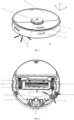
FIG. 1 is an oblique view of an automatic cleaning device according to some embodiments of the present disclosure; -
FIG. 2 is a schematic structural diagram of a bottom of an automatic cleaning device according to some embodiments of the present disclosure; -
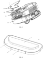
FIG. 3 is a schematic structural diagram of assembling of a button assembly of an automatic cleaning device according to some embodiments of the present disclosure; -
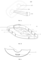
FIG. 4 is a schematic top view of a button cap of an automatic cleaning device according to some embodiments of the present disclosure; -
FIG. 5a is a schematic bottom view of a button cap of an automatic cleaning device according to some embodiments of the present disclosure; -
FIG. 5b is a schematic bottom view of a button cap of an automatic cleaning device according to some embodiments of the present disclosure; -
FIG. 6 is a schematic top view of a decorative cover of an automatic cleaning device according to some embodiments of the present disclosure; -
FIG. 7 is a schematic structural diagram of a cover plate of an automatic cleaning device according to some embodiments of the present disclosure; -
FIG. 8a is an enlarged schematic structural diagram of an upper side of a button bracket of an automatic cleaning device according to some embodiments of the present disclosure; -
FIG. 8b is an enlarged schematic structural diagram of a lower side of a button bracket of an automatic cleaning device according to some embodiments of the present disclosure; -
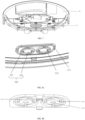
FIG. 9 is a schematic structural diagram of assembling of a button assembly of an automatic cleaning device according to some embodiments of the present disclosure; and -
FIG. 10 is a schematic diagram of a sectional structure of a button assembly of an automatic cleaning device according to some embodiments of the present disclosure. - Reference numerals in the drawings:
mobile platform 100; backwardportion 110;forward portion 111;sensing system 120;position determination unit 121;buffer 122;cliff sensor 123;control system 130;driving system 140;driving wheel assembly 141;steering assembly 142;cleaning module 150;dry cleaning module 151;side brush 152; main brush module 153;dust box 300; filter screen 500;energy system 160; human-machine interaction system 170;cover plate 200;button assembly 400;button cap 410;hard bracket 420; button cappressing portion 411; buttoncap skirt border 412;decorative cover 300;mounting hole 310;groove 211;protruding rim 413;protrusion 414;button hole 212;elastic arm 421;button ring 422; firstprotruding portion 417; secondprotruding portion 418;columnar structure 4181;conical structure 4182;flat structure 4183;button plate 423;pressing portion 4231;conical protrusion 4232. - To make the objectives, technical solutions and advantages of the present disclosure clearer, the present disclosure will be further described in detail in the following with reference to the drawings. Apparently, the described embodiments are only some, rather than all of the embodiments, in the present disclosure. Based on the embodiments of the present disclosure, all other embodiments obtained by those of ordinary skill in the art without creative efforts shall fall within the protection scope of the present disclosure.
- The terms used in the embodiments of the present disclosure are only for the purpose of describing particular embodiments, and are not intended to limit the present disclosure. The singular forms "alan", "the" and "said" used in the embodiments and the appended claims of the present disclosure are intended to include the plural forms as well, unless otherwise clearly indicated in the context. The term "a plurality of" generally includes at least two.
- It should be understood that the term "and/or" used herein only describes an associated relationship of associated objects, and indicates that there may be three kinds of relationships. For example, A and/or B can represent that A exists alone, A and B exist concurrently, and B exists alone. In addition, the character "j" herein generally indicates an "or" relationship between the contextual objects.
- It should be understood that although the terms first, second, third, etc. may be used in the embodiments of the present disclosure to describe certain objects, these objects should not be limited to these terms. These terms are only used to distinguish the objects. For example, a first object may also be referred to as a second object, and similarly, a second object may also be referred to as a first object, without departing from the scope of the embodiments of the present disclosure.
- It should also be noted that the terms "comprise", "include" or any other variants are intended to cover the nonexclusive inclusion, such that a commodity or device including a series of elements not only include those elements, but also include other elements not listed explicitly, or inherent elements of such commodity or device. Without more limitations, the element defined by the phrase "comprising a ..." does not exclude the existence of other identical elements in the commodity or device that includes such an element.
- Embodiments of the present disclosure will be described in detail in the following with reference to the drawings.
-
FIGS. 1 and 2 are schematic structural diagrams of an automatic cleaning device according to some embodiments of the present disclosure. As shown inFIGS. 1 and 2 , the automatic cleaning device may be a vacuum cleaning robot, or may be a mopping/brushing robot, or may be a window climbing robot, or the like. The automatic cleaning device may include amobile platform 100, asensing system 120, acontrol system 130, adriving system 140, acleaning module 150, anenergy system 160, and a human-machine interaction system 170. - The
mobile platform 100 may be configured to move automatically on an operation surface in a target direction. The operation surface may be a surface to be cleaned by the automatic cleaning device. In some embodiments, the automatic cleaning device may be a mopping robot, and is operated on a floor, which serves as the operation surface. The automatic cleaning device may also be a window cleaning robot, and is operated on an outer surface of the glass, which serves as the operation surface, of a building. The automatic cleaning device may also be a pipeline cleaning robot, and is operated on an inner surface, which serves as the operation surface, of a pipeline. Merely for the purpose of illustration, the following descriptions of the present disclosure are given by taking a mopping robot as an example. - In some embodiments, the
mobile platform 100 may be an autonomous mobile platform or a non-autonomous mobile platform. The autonomous mobile platform means that themobile platform 100 itself can automatically and adaptively make operation decisions according to unexpected environmental inputs, while the non-autonomous mobile platform itself, instead of adaptively making operation decisions according to unexpected environmental inputs, can execute given programs or run according to certain logic. Correspondingly, in the case where themobile platform 100 is the autonomous mobile platform, the target direction may be autonomously determined by the automatic cleaning device. In the case where themobile platform 100 is the non-autonomous mobile platform, the target direction may be set systematically or manually. When themobile platform 100 is the autonomous mobile platform, themobile platform 100 includes aforward portion 111 and abackward portion 110. - The
sensing system 120 includes aposition determination unit 121 located on themobile platform 100, abuffer 122 located at theforward portion 111 of themobile platform 100, and a sensing device such as acliff sensor 123, an ultrasonic sensor (not shown in the drawings), an infrared sensor (not shown in the drawings), a magnetometer (not shown in the drawings), an accelerometer (not shown in the drawings), a gyroscope (not shown in the drawings) and an odometer (not shown in the drawings), etc., which are located at the bottom of the mobile platform, for providing various position information and motion state information of the automatic cleaning device for thecontrol system 130. - In order to describe behaviors of the automatic cleaning device more clearly, directions are defined as follows: the automatic cleaning device may travel on the floor by means of various combinations of movements relative to the following three mutually perpendicular axes defined by the
mobile platform 100, i.e., a transversal axis Y, a front and back axis X, and a central vertical axis Z. A forward driving direction along the front and back axis X is designated as "forward", and a backward driving direction along the front and back axis X is designated as "backward". The transversal axis Y substantially extends between a right wheel and a left wheel of the automatic cleaning device along a center of an axis defined by a center point of adriving wheel assembly 141. The automatic cleaning device may rotate about the axis Y. It is referred to as "pitch up" when the forward portion of the automatic cleaning device is tilted upward and the backward portion thereof is tilted downward, and it is referred to as "pitch down" when the forward portion of the automatic cleaning device is tilted downward and the backward portion thereof is tilted upward. In addition, the automatic cleaning device may rotate around the axis Z. In the forward direction of the automatic cleaning device, it is referred to as "turn right" when the automatic cleaning device is tilted to the right of the axis X, and it is referred to as "turn left" when the automatic cleaning device is tilted to the left of the axis X. - As shown in
FIG. 2 , thecliff sensors 123 are disposed at the bottom of themobile platform 100 and in front and at rear of thedriving wheel assembly 141 and configured to prevent the automatic cleaning device from falling off when the automatic cleaning device moves back, so as to protect the automatic cleaning device against damage. The aforementioned "front" refers to a side in the same direction as a travelling direction of the automatic cleaning device, and the aforementioned "rear" refers to a side in a direction opposite to the travelling direction of the automatic cleaning device. - The
position determination unit 121 includes, but is not limited to, a camera and a laser distance sensor (LDS). - The various components in the
sensing system 120 may be operated independently or jointly to achieve intended functions more accurately. The surface to be cleaned is identified by thecliff sensor 123 and the ultrasonic sensor to determine the physical properties of the surface to be cleaned, including surface materials, the degree of cleanliness, etc., and may be more accurately determined in combination with the camera, and the LDS, etc. - For example, whether the surface to be cleaned is a carpet may be determined by the ultrasonic sensor, and if the ultrasonic sensor determines that the surface to be cleaned is made of a carpet material, the
control system 130 controls the automatic cleaning device to perform cleaning in a carpet mode. - The
forward portion 111 of themobile platform 100 is provided with thebuffer 122. Thebuffer 122 detects one or more events (or objects) in a travelling path of the automatic cleaning device via the sensing system (for example, an infrared sensor) when thedriving wheel assembly 141 propels the automatic cleaning device to travel on the floor in the process of cleaning. The automatic cleaning device may control thedriving wheel assembly 141 according to the events (or objects), such as an obstacle and a wall, detected by thebuffer 122, to enable the automatic cleaning device to respond to the events (or objects), for example, to move away from the obstacle. - The
control system 130 is disposed on a main circuit board in themobile platform 100, and includes a computing processor, such as a central processing unit or an application processor, which communicates with non-temporary memories, such as a hard disk, a flash memory and a random access memory. The application processor is configured to receive environmental information sensed by the plurality of sensors and transmitted from thesensing system 120, depict an instant map of an environment where the automatic cleaning device is located using a positioning algorithm, e.g., simultaneous localization and mapping (SLAM), according to obstacle information fed back by the LDS, and autonomously determine the travelling path according to the environmental information and the environmental map, to control thedriving system 140 to move forward, backward and/or steer according to the autonomously determined travelling path. In some embodiments, thecontrol system 130 may also determine, according to the environmental information and the environmental map, whether to activate thecleaning module 150 to perform a cleaning operation. - In some embodiments, the
control system 130 may comprehensively determine a current operation state of the sweeping robot, according to distance information and speed information fed back by thebuffer 122 and the sensing devices such as thecliff sensor 123, the ultrasonic sensor, the infrared sensor, the magnetometer, the accelerometer, the gyroscope and the odometer. The current operation state of the sweeping robot, for example, includes the sweeping robot is crossing a doorsill, moving onto a carpet, standing at an edge of a cliff, being stuck at the top or bottom, having a full dust box or being picked up. Thecontrol system 130 may also give specific next-step action strategies according to different situations, making the action of the automatic cleaning device more in line with the requirements of an owner, and providing better user experience. Furthermore, the control system may plan the most efficient and reasonable sweeping path and sweeping mode based on the information of the instant map depicted by SLAM, thereby greatly improving the sweeping efficiency of the automatic cleaning device. - The
driving system 140 may execute a driving command based on specific distance and angle information, such as x, y and θ components, to control the automatic cleaning device to travel across the floor. As shown inFIG. 2 , thedriving system 140 includes adriving wheel assembly 141 and may control a left wheel and a right wheel simultaneously. In order to control the movement of the automatic cleaning device more accurately, thedriving system 140 preferably includes a left driving wheel assembly and a right driving wheel assembly that are symmetrically arranged along a transversal axis defined by themobile platform 100. - In order to enable the automatic cleaning device to move on the floor more stably or have a stronger movement ability, the automatic cleaning device may include one or
more steering assemblies 142. Thesteering assemblies 142 may be driven wheels or driving wheels, and may structurally include but is not limited to universal wheels. Thesteering assemblies 142 may be located in front of thedriving wheel assembly 141. - The
energy system 160 includes a rechargeable battery, such as a nickel-hydrogen battery and a lithium battery. The rechargeable battery may be connected to a charging control circuit, a battery pack charging temperature detection circuit, and a battery undervoltage monitoring circuit, which are then connected to a single-chip microcomputer control circuit. A host of the automatic cleaning device is connected to a charging station through a charging electrode disposed on a side of or below the body of the automatic cleaning device for charging. If the exposed charging electrode is covered with dust, due to the accumulative effect of charges in the process of charging, a plastic body around the electrode will be melted and deformed and even the electrode itself will be deformed and thus is unable to continue to normally charge the automatic cleaning device. - The human-
machine interaction system 170 includes buttons that are on a panel of the host and used by a user to select functions. The human-machine interaction system 170 may further include a display screen and/or an indicator light and/or a speaker, as well as a mobile client program. The display, the indicator light and the speaker show the user the current state or function options of the automatic cleaning device. For a route navigation type cleaning device, a mobile client may show the user a map of the environment where the device is located, as well as the location of the device, thereby providing the user with richer and more user-friendly function items. - As shown in
FIG. 2 , thecleaning module 150 may include adry cleaning module 151. - The
dry cleaning module 151 includes a rolling brush, a dust box, a fan, and an air outlet. The rolling brush having certain interference with the floor sweeps up the garbage on the floor and rolls up the garbage to the front of a dust suction inlet between the rolling brush and the dust box. The garbage is then sucked into the dust box by air having a suction force, which is generated by the fan and passes through the dust box. The dust removal capacity of the sweeping robot can be characterized by a dust pickup (DPU) efficiency of the garbage. The DPU is affected by the structure and the material of the rolling brush, by a utilization rate of the air in an air passage formed by the dust suction inlet, the dust box, the fan, the air outlet and connecting parts among the dust suction inlet, the dust box, the fan and the air outlet, and by a type and a power of the fan, which is a complex problem in the system design. The improvement of the dust removal capacity is of greater significance to the energy-limited automatic cleaning device than an ordinary plug-in vacuum cleaner. This is because the improvement of the dust removal capacity directly and effectively reduces the demand for energy. That is, an original cleaning device capable of sweeping 80 square meters of the floor with one single charge may be improved to sweep 180 square meters or more with one single charge. In addition, the service life of a battery with a reduced number of charging times may be greatly prolonged, such that the frequency of replacing the battery by the user may be reduced. More intuitively and importantly, the improvement of the dust removal capacity is the most obvious and important user experience as the user can directly determine whether the thorough sweeping/mopping is achieved. The dry cleaning module may further include aside brush 152 provided with a rotating shaft at an angle respect to the floor, for moving the debris into a rolling brush area in thecleaning module 150. - As an optional cleaning module, the automatic cleaning device may further include a wet cleaning module configured to clean at least part of the operation surface in a wet cleaning manner. In some embodiments, the wet cleaning module includes a water tank, a cleaning head, a driving unit, and the like. Water from the water tank flows along a water path to the cleaning head, and the cleaning head cleans at least part of the operation surface under the driving of the driving unit.
- An existing pressing structure on a cover plate of the automatic cleaning device is complex. For example, for the existing cleaning devices, a button structure thereof is mostly provided as: a soft rubber bracket is disposed on a hard rubber bracket, a hard rubber button cap and the soft rubber bracket are bonded together, and then the soft rubber bracket and a decorative cover of an upper shell of the automatic cleaning device are bonded together with a double-sided adhesive, at the lower side, with the hard rubber bracket being fixed to the upper shell through a hook. Such a button assembly has a large number of parts and is complex in structure, which causes a long time in assembling, a complex process and a high cost. Due to a multi-layer structure of the button assembly, when the soft rubber bracket is bonded to the decorative cover of the upper shell of the automatic cleaning device, a deviation in mounting is easily caused by positioning with the soft rubber and it is difficult to disassemble the button. During disassembling, it is prone to cause the double-sided adhesive and the soft rubber to be torn up due to the high adhesion between the double-sided adhesive and the soft rubber, and thus the button cannot be used repeatedly.
- Embodiments of the present disclosure provide an automatic cleaning device, which simplifies unnecessary elements of the button assembly of the automatic cleaning device. The button assembly uses one part to enable a button to have functions of sealing, water resistance, light guide and light shielding, and meanwhile to enable the mounting, disassembling and maintenance of the button to be more convenient. In some embodiments, as shown in
FIG. 3 , the present disclosure provides an automatic cleaning device. The automatic cleaning device includes amobile platform 100 configured to automatically move on an operation surface. Themobile platform 100 includes acover plate 200. Thecover plate 200 is configured as at least a part of themobile platform 100 and may be an upper shell of a housing of themobile platform 100. Themobile platform 100 usually includes a front half portion for bearing a touch button and the like and a rear half portion for bearing a dust box and the like. The automatic cleaning device further includes abutton assembly 400 assembled to thecover plate 200. Thebutton assembly 400 is configured to receive a touch from a user, so that the automatic cleaning device can be controlled after being touched by the user. Thebutton assembly 400 includes aflexible button cap 410 and ahard bracket 420. Thebutton cap 410 is assembled to thebracket 420 for implementing pressing. As shown inFIG. 4 , thebutton cap 410 includes a buttoncap pressing portion 411 and a buttoncap skirt border 412 formed around the buttoncap pressing portion 411. The buttoncap pressing portion 411 and the buttoncap skirt border 412 form a vertically stacked structure, with the buttoncap pressing portion 411 being located above the buttoncap skirt border 412, so as to be convenience for the user to press. Outer contours of the buttoncap pressing portion 411 and the buttoncap skirt border 412 may be circular, square, rectangular, elliptical, D-shaped, or other shapes, which are not limited herein. As shown inFIG. 8a , thebracket 420 and thecover plate 200 are integrally formed through, for example, mold injection molding or mold compression molding at a later stage. As thebracket 420 is integrally formed, the step where the bracket and thecover plate 200 need to be assembled during the assembling process of the button assembly is omitted, and the light leakage and the water leakage that may be caused by too many assembling steps of elements are also avoided, as well as the assembly efficiency of the button assembly is improved. In some embodiments, as shown inFIGS. 3 and6 , the automatic cleaning device further includes adecorative cover 300 disposed on the top surface of thecover plate 200. Thedecorative cover 300 is usually configured to conceal irregular devices at the top of themobile platform 100 for providing an attractive appearance and the protection. As shown inFIG. 6 , thedecorative cover 300 includes a mountinghole 310 that matches with the buttoncap pressing portion 411 in shape. When thebutton cap 410 is assembled to thebracket 420, the buttoncap pressing portion 411 passes through the mountinghole 310, and meanwhile, an edge of the mountinghole 310 presses against the buttoncap skirt border 412. In this way, a tight connection is achieved between the mountinghole 310 and the buttoncap pressing portion 411, which avoids the light leakage and the water leakage. Alternatively, the buttoncap pressing portion 411 passes through the mountinghole 310 in an interference manner, which can further avoid the light leakage and the water leakage. - In some embodiments, as shown in
FIG. 7 , thecover plate 200 includes a buttoncap mounting portion 210 that substantially matches with the button cap skirt border in contour. The buttoncap mounting portion 210 is substantially a recessed structure, and a recessed contour of the buttoncap mounting portion 210 may also be circular, square, rectangular, elliptical, or D-shaped, which is not limited herein. When thebutton cap 400 is assembled to thebracket 420, the buttoncap skirt border 412 fits with the buttoncap mounting portion 210, and an upper surface of the buttoncap skirt border 412 is substantially coplanar with or is slightly higher than an upper surface of thecover plate 200. During the assembling process, the button cap is first placed on the buttoncap mounting portion 210, and thedecorative cover 300 is then pressed onto the buttoncap skirt border 412. Since the upper surface of the buttoncap skirt border 412 is substantially coplanar with or is slightly higher than the upper surface of thecover plate 200, sealing can be achieved by pressing the upper surface of the buttoncap skirt border 412 through thedecorative cover 300. In some embodiments, after thedecorative cover 300 presses against the upper surface of the buttoncap skirt border 412, the upper surface of the buttoncap skirt border 412 is still slightly higher than the upper surface of thecover plate 200, which can ensure the sealing performance of thedecorative cover 300. - In some embodiments, as shown in
FIG. 8a , the buttoncap mounting portion 210 includes agroove 211 extending circumferentially along an edge of the buttoncap mounting portion 210. The buttoncap skirt border 412 includes aprotruding rim 413 extending circumferentially along an edge of the buttoncap skirt border 412. when thebutton cap 400 is assembled to thebracket 420, the protrudingrim 413 is inserted into thegroove 211, so as to achieve complete sealing between the softrubber button cap 400 and thecover plate 200. In some embodiments, the protrudingrim 413 is inserted into thegroove 211 in an interference manner to achieve complete sealing between the softrubber button cap 400 and thecover plate 200. In some embodiments, as shown inFIG. 4 , at least one of an inner surface and an outer surface of the protrudingrim 413 includes at least oneprotrusion 414, and a structure of theprotrusion 414 is not limited. For example, theprotrusion 414 may be strip-shaped, bump-shaped or the like. Theprotrusion 414 can further seal the softrubber button cap 400 and thecover plate 200 to enhance water resistance and avoid light leakage, which can also increase the strength of the button cap, increase friction on a contact surface, and prevent misalignment in mounting. - In some embodiments, as shown in
FIGS. 9 and 10 , the buttoncap mounting portion 210 includes twobutton holes 212 disposed symmetrically, and thebracket 420 is integrally formed in the button holes. In some embodiments, for example, thebracket 420 includes abutton ring 422 connected through at least oneelastic arm 421. Thebutton ring 422 is disposed at an approximate center of the button hole. Thebutton ring 422 is connected to an inner wall of the button hole through one or twoelastic arms 421. Theelastic arm 421 may be disposed around thebutton ring 422, so as to increase a total length of the elastic arm, thereby increasing elasticity. The supporting strength is increased through roundabout embracement. Thebutton ring 422 is configured to bear thebutton cap 400, so that thebutton cap 400 can be pressed to implement a button function. Theelastic arm 421 is configured to enable thebutton ring 422 to restore its original position. The button ring and the elastic arm are made of a hard and elastic material, such as hard rubber or hard plastic or metal. - In some embodiments, as shown in
FIGS. 5a and10 , thebutton cap 400 further includes a first protrudingportion 417 and a second protrudingportion 418, which are disposed on a lower surface of the buttoncap pressing portion 410, and a lower surface of thebutton cap 400 includes a recessedportion 416 for accommodating the first protrudingportion 417 and the second protrudingportion 418. Each of the first protrudingportion 417 and the second protrudingportion 418 includes acolumnar structure 4181 extending downward from the lower surface of the button cap pressing portion and aconical structure 4182 extending downward from the columnar structure. Thecolumnar structure 4181 may be cylindrical or prismatic, theconical structure 4182 may be a circular boss or a pyramid, and the top surface of theconical structure 4182 is a flat pressing surface. Aflat structure 4183 is formed at a joint where thecolumnar structure 4181 is connected with theconical structure 4182. Theflat structure 4183 surrounds the joint where thecolumnar structure 4181 is connected with theconical structure 4182. When the button cap is s assembled to thebracket 420, the first protrudingportion 417 and the second protrudingportion 418 respectively pass through the button rings 422, and edges of the button rings 422 prop up the flat structure. It is convenient for theconical structures 4182 of the first protrudingportion 417 and the second protrudingportion 418 to extend into the button rings 422 and protrude from the button rings 422 to be in contact with pressed devices on a circuit board to implement pressing. - In some embodiments, the
mobile platform 100 further includes acircuit board 700 disposed below thebutton assembly 400. Thecircuit board 700 is provided with switch elements thereon, such as a micro-switch. Theconical structures 4182 of the first protrudingportion 417 and the second protrudingportion 418 are abutted against the switch element, and the switch element is triggered when subjected to a downward pressing force. - In some embodiments, the
bracket 420 includes abutton plate 423 connected through at least oneelastic arm 421. As shown inFIGS. 8a and 8b , thebutton plate 423 is configured to bear the button cap, so that the button cap can be pressed to achieve the button function. Theelastic arm 421 is configured to enable the button ring to restore its original position. In some embodiments, thebutton plate 423 includes a flat-plate pressing portion 4231 and aconical protrusion 4232. Thebutton plate 423 is integrally formed on an inner edge of thebracket 420 through one or more elongatedelastic arms 421. The one or more elongatedelastic arms 421 are disposed around thebutton plate 423, to provide thebutton plate 423 with sufficient elastic force for pressing and restoring. In some embodiments, as shown inFIG. 5b , the button cap 40 further includes a first protrudingportion 417 and a second protrudingportion 418, which are disposed on the lower surface of the buttoncap pressing portion 410. When the button cap is assembled to thebracket 420, the first protrudingportion 417 and the second protrudingportion 418 respectively fit with the upper surfaces of thebutton plates 423, to implement pressing. - In some embodiments, the
mobile platform 100 further includes acircuit board 700 disposed below thebutton assembly 400. Thecircuit board 700 is provided with switch elements thereon, such as a micro-switch. After the first protrudingportion 417 and the second protrudingportion 418 respectively fit with the upper surfaces of thebutton plates 423 to implement pressing, theconical protrusion 4232 is abutted against the switch element, and the switch element is triggered when subjected to a downward pressing force. - The present disclosure provides an automatic cleaning device. The button assembly is assembled to the cover plate of the automatic cleaning device. The button assembly includes the button cap and the bracket, and the button cap includes the button cap pressing portion and the button cap skirt border. The bracket and the cover plate are integrally formed. The button cap is directly assembled to the integrally formed bracket. The decorative plate presses against the button cap skirt border for fixing. As a result, the structure of the button cap assembly to be assembled can be simplified, thereby facilitating early assembling and later maintenance.
- It should be noted that the various embodiments in the specification are described in a progressive manner, each embodiment focuses on the differences from the other embodiments, and the same or similar parts among the various embodiments may refer to each other.
- The above embodiments are only used to illustrate the technical solutions of the present disclosure and are not intended to limit the present disclosure. Although the present disclosure has been described in detail with reference to the foregoing embodiments, those of ordinary skill in the art should understand that, they can still make modifications to the technical solutions disclosed in the above various embodiments or make equivalent substitutions to some of the technical features, and these modifications or substitutions do not make the essence of the corresponding technical solutions deviate from the spirit and scope of the technical solutions of the various embodiments of the present disclosure.
Claims (13)
- An automatic cleaning device, comprising:a mobile platform configured to automatically move on an operation surface and comprising a cover plate; anda button assembly assembled to the cover plate, wherein the button assembly comprises a button cap and a bracket, and the button cap is assembled to the bracket,wherein the bracket and the cover plate are integrally formed.
- The automatic cleaning device according to claim 1, wherein the button cap comprises a button cap pressing portion, and a button cap skirt border disposed around the button cap pressing portion.
- The automatic cleaning device according to claim 2, further comprising a decorative cover disposed on a top surface of the cover plate, wherein the decorative cover comprises a mounting hole that matches with the button cap pressing portion in shape, and when the button cap is assembled to the bracket, an edge of the mounting hole presses against the button cap skirt border.
- The automatic cleaning device according to claim 3, wherein the cover plate comprises a button cap mounting portion that substantially matches with the button cap skirt border in contour, and when the button cap is assembled to the bracket, the button cap skirt border fits with the button cap mounting portion, and an upper surface of the button cap skirt border is substantially coplanar with or is slightly higher than an upper surface of the cover plate.
- The automatic cleaning device according to claim 4, wherein the button cap mounting portion comprises a groove extending circumferentially along an edge, the button cap skirt border comprises a protruding rim extending circumferentially along an edge, and when the button cap is assembled to the bracket, the protruding rim is inserted into the groove.
- The automatic cleaning device according to claim 5, wherein an inner side and/or an outer side of the protruding rim comprise(s) at least one protrusion.
- The automatic cleaning device according to claim 4, wherein the button cap mounting portion comprises two button holes disposed symmetrically, and the bracket is integrally formed in the button holes.
- The automatic cleaning device according to claim 7, wherein the button cap further comprises a first protruding portion and a second protruding portion which are disposed on a lower surface of the button cap pressing portion, and when the button cap is assembled to the bracket, the first protruding portion and the second protruding portion implement pressing through the bracket.
- The automatic cleaning device according to claim 8, wherein the first protruding portion and the second protruding portion each comprises a columnar structure extending downward from the lower surface of the button cap pressing portion and a conical structure extending downward from the columnar structure, and a flat structure is formed at a joint where the columnar structure is connected with the conical structure.
- The automatic cleaning device according to claim 9, wherein the bracket comprises at least one elastic arm and a button ring connected through the at least one elastic arm, the button ring is configured to prop up the flat structure after the conical structure passes through the button ring, and the elastic arm is configured to enable the button ring to restore an original position thereof.
- The automatic cleaning device according to claim 8, wherein the bracket comprises at least one elastic arm and a button plate connected through the at least one elastic arm, the button plate is configured to transmit a pressing force through the first protruding portion and the second protruding portion when the button cap is pressed, and the elastic arm is configured to enable the button plate to restore an original position thereof.
- The automatic cleaning device according to claim 11, wherein a lower surface of the button plate comprises a conical protrusion, and the conical protrusion is configured for use in implementing pressing.
- The automatic cleaning device according to claim 9 or 12, further comprising a switch element configured to be triggered by pressing applied through the conical structure or the conical protrusion.
Applications Claiming Priority (2)
| Application Number | Priority Date | Filing Date | Title |
|---|---|---|---|
| CN202220023511.5U CN216907817U (en) | 2022-01-05 | 2022-01-05 | Automatic cleaning equipment and system |
| PCT/CN2022/101608 WO2023130681A1 (en) | 2022-01-05 | 2022-06-27 | Automatic cleaning apparatus, and system |
Publications (2)
| Publication Number | Publication Date |
|---|---|
| EP4461186A1 true EP4461186A1 (en) | 2024-11-13 |
| EP4461186A4 EP4461186A4 (en) | 2026-01-07 |
Family
ID=82256081
Family Applications (1)
| Application Number | Title | Priority Date | Filing Date |
|---|---|---|---|
| EP22918137.5A Pending EP4461186A4 (en) | 2022-01-05 | 2022-06-27 | AUTOMATIC CLEANING DEVICE AND SYSTEM |
Country Status (7)
| Country | Link |
|---|---|
| US (1) | US20250089964A1 (en) |
| EP (1) | EP4461186A4 (en) |
| JP (1) | JP2025503812A (en) |
| KR (1) | KR20240129026A (en) |
| CN (1) | CN216907817U (en) |
| AU (1) | AU2022430603B2 (en) |
| WO (1) | WO2023130681A1 (en) |
Families Citing this family (7)
| Publication number | Priority date | Publication date | Assignee | Title |
|---|---|---|---|---|
| JP1766127S (en) * | 2022-12-06 | 2024-03-21 | cleaning robot | |
| CN116130277B (en) * | 2022-12-13 | 2025-12-12 | 深圳市优纪元科技有限公司 | A button, housing, and electronic device |
| CN120344367A (en) | 2022-12-16 | 2025-07-18 | 三菱化学株式会社 | Method for producing particle-containing fiber bundle and particle-containing fiber bundle |
| JP1771034S (en) * | 2022-12-30 | 2024-05-21 | Cleaning robot | |
| USD1082190S1 (en) * | 2023-06-12 | 2025-07-01 | Samsung Electronics Co., Ltd. | Robot vacuum cleaner |
| CA232105S (en) * | 2024-01-05 | 2025-05-01 | Beijing Roborock Technology Co Ltd | Cleaning robot |
| CA234408S (en) * | 2024-03-25 | 2025-10-22 | Beijing Roborock Technology Co Ltd | Self-cleaning part of docking station for cleaning appliance |
Family Cites Families (16)
| Publication number | Priority date | Publication date | Assignee | Title |
|---|---|---|---|---|
| DE3428033A1 (en) * | 1984-07-30 | 1986-01-30 | Siemens AG, 1000 Berlin und 8000 München | Key switch set for a vacuum cleaner |
| JPS6314321U (en) * | 1986-07-11 | 1988-01-30 | ||
| JPH0472520U (en) * | 1990-11-06 | 1992-06-25 | ||
| KR100190665B1 (en) * | 1996-12-27 | 1999-06-01 | 전주범 | Mounting structure of controlling the suction power for vacuum cleaner |
| US9757004B2 (en) * | 2015-02-12 | 2017-09-12 | Irobot Corporation | Liquid management for floor-traversing robots |
| JP2016219347A (en) * | 2015-05-25 | 2016-12-22 | フォスター電機株式会社 | Control unit and manufacturing method thereof |
| CN205697557U (en) * | 2015-10-17 | 2016-11-23 | 胡永纲 | A kind of panel construction on sweeping robot |
| CN205083394U (en) * | 2015-10-23 | 2016-03-16 | 江苏美的清洁电器股份有限公司 | Dust catcher and button thereof |
| JP6588832B2 (en) * | 2016-01-14 | 2019-10-09 | 東京パーツ工業株式会社 | Door handle device |
| JP6886787B2 (en) * | 2016-08-03 | 2021-06-16 | 東芝ライフスタイル株式会社 | Electrical equipment and vacuum cleaner |
| JP2018061539A (en) * | 2016-10-11 | 2018-04-19 | 日立アプライアンス株式会社 | Electric vacuum cleaner |
| CN206076120U (en) * | 2016-10-17 | 2017-04-05 | 江苏美的清洁电器股份有限公司 | Press-key structure and vacuum cleaner |
| CN110151067A (en) * | 2019-05-31 | 2019-08-23 | 尚科宁家(中国)科技有限公司 | Sweeper |
| CN214387360U (en) * | 2020-12-28 | 2021-10-15 | 深圳市银星智能科技股份有限公司 | Panel assembly and cleaning robot |
| CN215078054U (en) * | 2021-04-07 | 2021-12-10 | 美智纵横科技有限责任公司 | Button device of cleaning robot and cleaning robot |
| CN113679313A (en) * | 2021-06-29 | 2021-11-23 | 深圳市银星智能科技股份有限公司 | Sealing method for surface cover and middle shell of cleaning robot and cleaning robot |
-
2022
- 2022-01-05 CN CN202220023511.5U patent/CN216907817U/en active Active
- 2022-06-27 US US18/726,864 patent/US20250089964A1/en active Pending
- 2022-06-27 JP JP2024540795A patent/JP2025503812A/en active Pending
- 2022-06-27 KR KR1020247025708A patent/KR20240129026A/en active Pending
- 2022-06-27 WO PCT/CN2022/101608 patent/WO2023130681A1/en not_active Ceased
- 2022-06-27 AU AU2022430603A patent/AU2022430603B2/en active Active
- 2022-06-27 EP EP22918137.5A patent/EP4461186A4/en active Pending
Also Published As
| Publication number | Publication date |
|---|---|
| JP2025503812A (en) | 2025-02-05 |
| EP4461186A4 (en) | 2026-01-07 |
| WO2023130681A1 (en) | 2023-07-13 |
| AU2022430603A1 (en) | 2024-08-22 |
| US20250089964A1 (en) | 2025-03-20 |
| CN216907817U (en) | 2022-07-08 |
| KR20240129026A (en) | 2024-08-27 |
| AU2022430603B2 (en) | 2025-12-04 |
Similar Documents
| Publication | Publication Date | Title |
|---|---|---|
| AU2022430603B2 (en) | Automatic cleaning device | |
| EP4011266B1 (en) | Sealing structure and smart cleaning apparatus | |
| EP3690591B1 (en) | Autonomous mobile robot and charging station seeking method therefor, control apparatus and smart cleaning system | |
| US12369766B2 (en) | Blocking plug and intelligent cleaning device | |
| AU2022434150B2 (en) | Automatic cleaning device and system | |
| AU2022434156B2 (en) | Automatic cleaning device | |
| JP2025501387A (en) | Automatic cleaning device | |
| JP7717289B2 (en) | Automatic Cleaning Device | |
| CN218451585U (en) | Automatic cleaning equipment | |
| JP7808698B2 (en) | Automatic cleaning device | |
| EP4691330A1 (en) | Automatic cleaning apparatus | |
| US11849909B2 (en) | Automatic cleaning apparatus | |
| CN218500627U (en) | Cleaning device and system | |
| JP2026082988A (en) | Automatic cleaning device and system | |
| CN115251762B (en) | Cleaning device and system | |
| AU2022337419B2 (en) | Button structure, liquid storage tank, and automatic cleaning device | |
| EP4578358A1 (en) | Automatic cleaning device, and system |
Legal Events
| Date | Code | Title | Description |
|---|---|---|---|
| STAA | Information on the status of an ep patent application or granted ep patent |
Free format text: STATUS: THE INTERNATIONAL PUBLICATION HAS BEEN MADE |
|
| PUAI | Public reference made under article 153(3) epc to a published international application that has entered the european phase |
Free format text: ORIGINAL CODE: 0009012 |
|
| STAA | Information on the status of an ep patent application or granted ep patent |
Free format text: STATUS: REQUEST FOR EXAMINATION WAS MADE |
|
| 17P | Request for examination filed |
Effective date: 20240802 |
|
| AK | Designated contracting states |
Kind code of ref document: A1 Designated state(s): AL AT BE BG CH CY CZ DE DK EE ES FI FR GB GR HR HU IE IS IT LI LT LU LV MC MK MT NL NO PL PT RO RS SE SI SK SM TR |
|
| DAV | Request for validation of the european patent (deleted) | ||
| DAX | Request for extension of the european patent (deleted) | ||
| A4 | Supplementary search report drawn up and despatched |
Effective date: 20251204 |
|
| RIC1 | Information provided on ipc code assigned before grant |
Ipc: A47L 11/40 20060101AFI20251128BHEP Ipc: A47L 11/24 20060101ALI20251128BHEP |