EP4461173A1 - Cooking appliance comprising viewing window and image sensor for capturing images through the viewing window - Google Patents
Cooking appliance comprising viewing window and image sensor for capturing images through the viewing window Download PDFInfo
- Publication number
- EP4461173A1 EP4461173A1 EP23172123.4A EP23172123A EP4461173A1 EP 4461173 A1 EP4461173 A1 EP 4461173A1 EP 23172123 A EP23172123 A EP 23172123A EP 4461173 A1 EP4461173 A1 EP 4461173A1
- Authority
- EP
- European Patent Office
- Prior art keywords
- viewing window
- cooking chamber
- cooking
- cooking appliance
- airflow
- Prior art date
- Legal status (The legal status is an assumption and is not a legal conclusion. Google has not performed a legal analysis and makes no representation as to the accuracy of the status listed.)
- Withdrawn
Links
Images





Classifications
-
- A—HUMAN NECESSITIES
- A47—FURNITURE; DOMESTIC ARTICLES OR APPLIANCES; COFFEE MILLS; SPICE MILLS; SUCTION CLEANERS IN GENERAL
- A47J—KITCHEN EQUIPMENT; COFFEE MILLS; SPICE MILLS; APPARATUS FOR MAKING BEVERAGES
- A47J37/00—Baking; Roasting; Grilling; Frying
- A47J37/06—Roasters; Grills; Sandwich grills
- A47J37/0623—Small-size cooking ovens, i.e. defining an at least partially closed cooking cavity
- A47J37/0629—Small-size cooking ovens, i.e. defining an at least partially closed cooking cavity with electric heating elements
- A47J37/0641—Small-size cooking ovens, i.e. defining an at least partially closed cooking cavity with electric heating elements with forced air circulation, e.g. air fryers
-
- F—MECHANICAL ENGINEERING; LIGHTING; HEATING; WEAPONS; BLASTING
- F24—HEATING; RANGES; VENTILATING
- F24C—DOMESTIC STOVES OR RANGES ; DETAILS OF DOMESTIC STOVES OR RANGES, OF GENERAL APPLICATION
- F24C15/00—Details
- F24C15/32—Arrangements of ducts for hot gases, e.g. in or around baking ovens
- F24C15/322—Arrangements of ducts for hot gases, e.g. in or around baking ovens with forced circulation
- F24C15/325—Arrangements of ducts for hot gases, e.g. in or around baking ovens with forced circulation electrically-heated
-
- F—MECHANICAL ENGINEERING; LIGHTING; HEATING; WEAPONS; BLASTING
- F24—HEATING; RANGES; VENTILATING
- F24C—DOMESTIC STOVES OR RANGES ; DETAILS OF DOMESTIC STOVES OR RANGES, OF GENERAL APPLICATION
- F24C7/00—Stoves or ranges heated by electric energy
- F24C7/08—Arrangement or mounting of control or safety devices
- F24C7/082—Arrangement or mounting of control or safety devices on ranges, e.g. control panels, illumination
- F24C7/085—Arrangement or mounting of control or safety devices on ranges, e.g. control panels, illumination on baking ovens
-
- F—MECHANICAL ENGINEERING; LIGHTING; HEATING; WEAPONS; BLASTING
- F24—HEATING; RANGES; VENTILATING
- F24C—DOMESTIC STOVES OR RANGES ; DETAILS OF DOMESTIC STOVES OR RANGES, OF GENERAL APPLICATION
- F24C15/00—Details
- F24C15/008—Illumination for oven cavities
Definitions
- This invention relates to a cooking appliance having a viewing window for enabling an image sensor to capture images of food being cooked in the cooking appliance through the viewing window.
- cooking appliance such as table-top cooking appliances that are positionable by the consumer on a table-top or kitchen countertop.
- Air fryers are already common kitchen appliances but their popularity continues to grow. Air fryers may, for example, take the form of portable ovens which are designed to fit on a kitchen work surface.
- Air fryers can be distinguished from conventional convection ovens at least partly by the direction of air circulation through the cooking chamber.
- the air fryer's cooking chamber has, when orientated for use, a top and a bottom.
- a circulation system e.g. in the form of a fan driven by a motor, is arranged to circulate air upwardly through food received in the cooking chamber in the direction of the top and/or downwardly through food received in the cooking chamber in the direction of the bottom.
- Another type of table-top cooking appliance is the so-called air cooker, whose circulation system may be arranged to circulate air laterally, e.g. horizontally, across and through food received in the cooking chamber, with the air being laterally directed towards a side portion of the cooking chamber.
- Including an image sensor in a cooking appliance can play an important role in smart assisted cooking.
- a food type can be recognized by food image recognition and a cooking setting can be determined based on food image analysis.
- food images can be used for cooking process control, browning control, remote monitoring, burning prevention, and content for social media sharing.
- image sensors in cooking appliances include capturing images and/or video for identification of food amount, e.g. volume, food distribution within the cooking chamber, and doneness level.
- the relatively rapid airflow in cooking appliances having circulation systems, and in air fryers in particular, together with aerosols generated during cooking can cause rapid pollution of a viewing window, in other words viewport, through which the image sensor captures images of the food received in the cooking chamber.
- Such pollution can mean that algorithms, e.g. trained algorithms, employed to derive the above-mentioned food-related information from image(s) of the food may be unable to function reliably.
- the viewing window may be polluted to such an extent that even capturing an image of the cooking chamber through the viewing window is precluded.
- a cooking appliance comprising: a cooking chamber; a heating element; a viewing window; an image sensor arranged to enable image capture of food received in the cooking chamber through the viewing window; a circulation system arranged to circulate air heated by the heating element in the cooking chamber; and a flow guiding element arranged in a path of an airflow provided by the circulation system in a direction of the viewing window, the flow guiding element comprising a ramp arranged to displace at least part of the airflow away from the viewing window and guide said at least part of the airflow across the viewing window.
- the ramp of the flow guiding element redirecting the airflow away from the viewing window, e.g. from a plane of the viewing window, pollution of the viewing window by, in particular, aerosols generated during cooking of the food received in the cooking chamber can be alleviated.
- the flow guiding element may provide minimal disruption to heated air circulation in the cooking chamber, and therefore may exert minimal influence over cooking of the food received in the cooking chamber.
- plane of the viewing window may refer to a plane of a planar surface of the viewing window, e.g. that is exposed to the interior of the cooking chamber.
- plane of the viewing window may refer to a plane that is tangential to a non-planar surface of the viewing window, e.g. that is exposed to the interior of the cooking chamber.
- Such a tangential plane may, for example, extend perpendicular to a normal extending through a center of the viewing window.
- plan of the viewing window is not intended to refer only to planar viewing windows.
- the viewing window is non-planar, e.g. having a non-planar surface.
- non-planar viewing windows may include viewing windows having a curved contour, e.g. a convex surface.
- Such a non-planar viewing window may, for example, be a lens, e.g. provided in addition to a lens included in the image sensor arranged behind the viewing window.
- the airflow may be provided along an interior surface delimiting, or arranged within, the cooking chamber.
- the airflow may be a surface airflow provided along such an interior surface.
- the interior surface is included in a surface of the cooking chamber wall that delimits the cooking chamber.
- the interior surface may be included in a surface of a partition wall arranged in the cooking chamber.
- the flow guiding element comprises a protrusion that protrudes from the interior surface along which the airflow is provided.
- Such a protrusion may provide a relatively straightforward and effective way of implementing the flow guiding element, for example relative to alternative solutions involving a ramp-comprising recess defined in the interior surface.
- the protrusion extends at least partly around the viewing window, for example with the ramp also extending at least partly around the viewing window.
- the protrusion may displace air flowing from various directions towards the viewing window away from the plane of the viewing window, and across the viewing window.
- the protrusion may, for example, delimit a hole, e.g. a frustroconical hole, through which light passes to reach the viewing window.
- the protrusion is detachable from the interior surface.
- This may assist with cleaning the viewing window (as well as the protrusion itself), particularly in embodiments in which the protrusion extends at least partly around the viewing window.
- the ramp extends in the direction of the viewing window to a point that is spaced apart from the viewing window along an axis extending normal to the viewing window.
- the ramp may extend to a height that is different from that of the plane of the viewing window, thereby facilitating displacement of the airflow away from the plane of the viewing window and across the viewing window.
- the flow guiding element may comprise a defined edge at which extension of the ramp in the direction of the viewing window terminates. Such a defined, e.g. sharp, edge may assist to ensure that the airflow initially guided up the ramp is directed by the flow guiding element across, rather than back towards, the viewing window.
- the flow guiding element is arranged to guide a portion of the airflow, e.g. passing along the interior surface, laterally around the viewing window.
- Such lateral guiding of the airflow around the viewing window may assist to minimize disruption caused by the flow guiding element to heated air circulation in the cooking chamber, and may thus assist to minimize the flow guiding element's influence over cooking of the food received in the cooking chamber.
- the flow guiding element comprises sides that face in directions transverse to the airflow, with one or both of the sides being connected to a base of the ramp via a curved portion that curvedly extends from the ramp around to the respective side.
- Such curved portion(s) may assist the flow guiding element to guide a portion of the airflow laterally around the viewing window.
- the viewing window is arranged in a cooking chamber wall that at least partly delimits the cooking chamber.
- the viewing window may be arranged in the partition wall located within the cooking chamber.
- an inner surface of the partition wall may at least partly delimit an inner cooking chamber arranged within the cooking chamber.
- a duct may be defined between the cooking chamber wall that at least partly delimits the cooking chamber and an outer surface of the partition wall.
- the circulation system may be arranged to circulate at least part of the heated air around the duct, into and through the inner cooking chamber, and back into the duct, with the duct being arranged to fluidly connect a top and a bottom of the inner cooking chamber to each other such that the circulating at least part of the heated air passing through the inner cooking chamber traverses a height of the inner cooking chamber.
- the heated air By the heated air passing through the inner cooking chamber traversing a height of the inner cooking chamber, the heated air may be delivered through food received in the inner cooking chamber. This may assist to achieve frying-type cooking effect.
- an air guide member is arranged to guide the at least part of the heated air circulated by the circulation system into the inner cooking chamber, and along the inner surface of the partition wall in the direction of the viewing window.
- the air guide member may be arranged in the duct.
- the air guide member may assist to guide the at least part of the heated air from the duct into the inner cooking chamber.
- the air guide member may assist to provide the airflow along the interior surface in the direction of the viewing window.
- the air guide member is arranged to guide the airflow along the interior surface, e.g. the inner surface of the partition wall.
- the air guide member may be arranged to provide a rotational component to the airflow, such that the path of the airflow winds around the interior surface.
- This rotational component may be provided in addition to the airflow's traversing of the height of the inner cooking chamber.
- the cooking chamber and the circulation system may be arranged such that, when the cooking appliance is orientated for use, at least part of the heated air traverses a height of the cooking chamber.
- upward and/or downward heated airflow through the cooking chamber may not require the partition wall, the inner cooking chamber and the duct described above.
- the partition wall, the inner cooking chamber and the duct may be omitted.
- the cooking appliance may include a perforate food supporting base, e.g. a mesh or grid plate, arranged or arrangeable inside the cooking chamber for supporting food.
- a perforate food supporting base e.g. a mesh or grid plate, arranged or arrangeable inside the cooking chamber for supporting food.
- mass heated air circulation within the cooking chamber may be provided, with both upward and downward airflow directions through the cooking chamber being possible.
- the cooking chamber may be at least partly delimited by a base portion, a top portion, and a side portion extending between the base portion and the top portion.
- base and top in this context may refer to an in-use orientation of the cooking appliance, for example when the cooking appliance is positioned on a kitchen table or countertop, with the base portion being proximal to the kitchen table or countertop, the top portion being distal with respect to the kitchen table or countertop, and the side portion upstanding from the base portion in the direction of the top portion.
- the viewing window is arranged in or proximal to the top portion. Such positioning of the viewing window may facilitate capturing of images of the food received in the cooking chamber.
- the flow guiding element may be arranged at or proximal to the top portion.
- the flow guiding element and the viewing window may both be arranged at or proximal to the top portion.
- the flow guiding element may be arranged to minimize pollution of the viewing window arranged in or proximal to the top portion.
- proximal to in this context may mean that the relevant component, e.g. the flow guiding element and/or the viewing window, is arranged at/in the side portion but closer to the top portion than to the base portion.
- the ramp slopes from the top portion downwardly towards the base portion. Airflow may therefore be guided downwardly by the ramp towards the base portion of the cooking chamber, and thus away from the viewing window, e.g. away from the viewing window arranged in the top portion.
- the top portion comprises a heat reflector.
- a heat reflector may, among other things, assist to protect the image sensor from the heat within the cooking chamber when the viewing window is arranged in the heat reflector and/or in an upper part of the side portion.
- the cooking appliance comprises a seal around the viewing window for restricting fluid passage around the viewing window towards the image sensor.
- Such a seal may assist to minimize the risk of damage to the image sensor, for example by hot air and/or steam passing between the cooking chamber wall, or the partition wall, and the viewing window.
- the cooking appliance comprises at least one light emitter arranged to illuminate at least part of the cooking chamber through the viewing window and/or through a further window arranged adjacent to the viewing window.
- the ramp of the flow guiding element may be arranged to displace at least part of the airflow away from the further window, e.g. a plane of the further viewing window, and guide the at least part of the airflow across the further window.
- the alleviation of pollution of the viewing window and/or the further window by the flow guiding element may also assist to minimize disruption to illumination of the cooking chamber provided by the light emitter(s).
- the cooking appliance may be a domestic cooking appliance, for example a domestic cooking appliance in the form of a table-top cooking appliance.
- the cooking appliance e.g. domestic cooking appliance, may be an oven.
- Such an oven may, for example, be a table-top oven or a built-in type oven for installation in a kitchen.
- the cooking appliance is an air fryer or an air cooker.
- the air fryer and the air cooker may be examples of table-top cooking appliances.
- the circulation system may be arranged to circulate air upwardly through food received in the cooking chamber in the direction of the top portion and/or downwardly through food received in the cooking chamber in the direction of the base portion.
- the circulation system may be arranged to circulate air laterally across and through food received in the cooking chamber, with the air being laterally directed towards the side portion.
- a cooking appliance comprising a cooking chamber, a heating element, and a circulation system arranged to circulate air heated by the heating element in the cooking chamber.
- the circulation system provides an airflow within the cooking chamber, e.g. along an interior surface delimiting, or arranged within, the cooking chamber.
- the cooking appliance further comprises a viewing window towards which the airflow is directed, and an image sensor arranged to enable image capture of food received in the cooking chamber through the viewing window.
- a flow guiding element is arranged in a path of the airflow.
- the flow guiding element comprises a ramp arranged to displace at least part of the airflow away from the viewing window, e.g. away from a plane of the viewing window, and guide the at least part of the airflow across the viewing window.
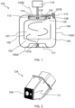
- FIG. 1 schematically depicts a cooking appliance 100 according to an example.
- the cooking appliance 100 in this example is in the form of an air fryer.
- the present disclosure is more generally applicable to any type of cooking appliance 100.
- the cooking appliance 100 being a domestic cooking appliance 100, for example a domestic cooking appliance 100 in the form of a table-top cooking appliance 100.
- the cooking appliance 100 is an air cooker. It is noted that the air fryer and the air cooker may be examples of table-top cooking appliances 100.
- the cooking appliance 100 comprises a cooking chamber 102 in which food (not visible) is receivable.
- the cooking chamber 102 may be at least partly delimited by a cooking chamber wall 103.
- the cooking chamber 102 may be at least partly delimited by a base portion 103A, a top portion 103B, and a side portion 103C extending between the base portion 103A and the top portion 103B.
- the base portion 103A, the top portion 103B, and the side portion 103C may be included in, e.g. may define, the cooking chamber wall 103.
- base and top in this context may refer to an in-use orientation of the cooking appliance 100, as shown in FIG. 1 .
- Such an in-use orientation may be adopted, for example, when the cooking appliance 100 is positioned on a kitchen table or countertop, with the base portion 103A being proximal to the kitchen table or countertop, the top portion 103B being distal with respect to the kitchen table or countertop, and the side portion 103C upstanding from the base portion 103A in the direction of the top portion 103B.
- the cooking appliance 100 includes a partition wall 106 whose inner surface at least partly delimits an inner cooking chamber 107 arranged within the cooking chamber 102.
- food may be received specifically within the inner cooking chamber 107.
- the top portion 103B comprises a heat reflector.
- a heat reflector may, among other things, assist to protect sensitive components of the cooking appliance 100, such as control circuitry, from the heat within the cooking chamber 102.
- the heat reflector may be formed from any suitable material, such as a metal or metal alloy, e.g. steel.
- the heat reflector is preferably formed from galvanized plate metal.
- the cooking appliance 100 comprises a viewing window 108, whose function will be explained in more detail herein below.
- the viewing window 108 is arranged in the cooking chamber wall 103.
- the viewing window 108 may be arranged in, or at least proximal to, the top portion 103B.
- the viewing window 108 is arranged in the partition wall 106, subject, of course, to the cooking appliance 100 including such a partition wall 106.
- a duct 109 may be defined between the cooking chamber wall 103 and an outer surface of the partition wall 106. Heated air may be circulated around the duct 109, into and through the inner cooking chamber 107, and back into the duct 109.
- the duct 109 may be arranged to fluidly connect a top and a bottom of the inner cooking chamber 107 to each other such that the circulating heated air passing through the inner cooking chamber 107 traverses a height of the inner cooking chamber 107.
- one or more apertures 107A may be provided in a bottom of the inner cooking chamber 107, with one or more openings 107B being provided in the top of the inner cooking chamber 107.
- the duct 109 may provide a fluid connection between the opening(s) 107B and the aperture(s) 107A that extends around the outer surface of the partition wall 106.
- the aperture(s) 107A may be defined by apertures of a perforate food supporting base.
- the perforate food supporting base may be regarded as a platform on which food for cooking/baking/frying/steaming may be supported.
- the cooking appliance 100 comprises a basket whose bottom portion corresponds to the perforate food supporting base.
- the cooking chamber 102 may be arranged such that, when the cooking appliance 100 is orientated for use, at least part of the heated air traverses a height of the cooking chamber 102.
- the traversing of the height of the cooking chamber 102 may mean that the at least part of the heated air passes upwardly and/or downwardly through the cooking chamber 102.
- this traversing of the height of the cooking chamber 102 may mean upward and/or downward heated airflow through the food received in the cooking chamber 102. This may assist to provide the frying effect provided by the cooking appliance 100, e.g. air fryer.
- the cooking appliance 100 may include a perforate food supporting base, e.g. a mesh or grid plate, arranged or arrangeable inside the cooking chamber 102 for supporting food.
- a perforate food supporting base e.g. a mesh or grid plate
- mass heated air circulation within the cooking chamber 102 may be provided, with both upward and downward airflow directions through the cooking chamber 102 being possible.
- the cooking appliance 100 comprises an image sensor 110 arranged to enable image capture of food received in the cooking chamber 102, e.g. received in the inner cooking chamber 107 in the case of the non-limiting examples shown in FIGs. 1 , 3A to 3C and 4 , through the viewing window 108.
- Such image capture may enable identification of a food type, amount, distribution and/or doneness level of the food received in the cooking chamber 102, e.g. in the inner cooking chamber 107.
- Such identification may be implemented via image analysis performed by a processing system included in the cooking appliance 100 and/or in a processing system included in a cloud-based server and/or in an external user device, such as a smartphone or tablet computer, separate from the cooking appliance 100.
- image sensor 110 Any suitable type of image sensor 110 may be contemplated, for example a charge coupled device (CCD) image sensor 110 or a complementary metal-oxide-semiconductor (CMOS) image sensor 110.
- CCD charge coupled device
- CMOS complementary metal-oxide-semiconductor
- the viewing window 108 is formed of a suitable optically transmissive/transparent and thermally robust material.
- the viewing window 108 may be made of glass.
- Such a viewing window 108 e.g. a glass window 108, arranged between the cooking chamber 102, e.g. the inner cooking chamber 107, and the image sensor 110 may assist to protect the image sensor 110 from cooking conditions in the cooking chamber 102.
- the cooking appliance 100 comprises a seal around the viewing window 108 for restricting fluid passage around the viewing window 108 towards the image sensor 110.
- Such a seal may assist to minimize the risk of damage to the image sensor 110, for example by hot air and/or steam passing between the cooking chamber wall 103, or the partition wall 106, and the viewing window 108.
- the image sensor 110 and the viewing window 108 may be arranged so that the image sensor 110 can capture images of the inner cooking chamber 107 through the duct 109.
- a gap may be defined in the partition wall 106, through which gap the image sensor 110 can capture images of the inner cooking chamber 107.
- the cooking appliance 100 comprises at least one light emitter arranged to illuminate at least part of the cooking chamber 102, e.g. the inner cooking chamber 107, through the viewing window 108 and/or through a further window 111.
- the at least one light emitter comprises one or more light emitting diodes.
- the further window 111 may be arranged adjacent to the viewing window 108.
- the viewing window 108 may be regarded as being included in, e.g. may be defined by, a transparent plate. Alternatively, the viewing window 108 may be included in a window assembly comprising a plurality of transparent elements.
- the further window 111 and the viewing window 108 may, for example, correspond to respective transparent elements included in such a window assembly. An example of this is shown in FIG. 2 .
- the image sensor 110 and the viewing window 108 may be included, e.g. together with the light emitter(s) and/or the further window 111, if present, in a camera assembly CA.
- Such a camera assembly CA may facilitate mounting of the image sensor 110 and the viewing window 108 in the cooking appliance 100, since the camera assembly CA may define the spatial relationship between the image sensor 110 and the viewing window 108 prior to the camera assembly CA being positioned in the cooking appliance 100.
- the cooking appliance 100 includes a heating element 112, and a circulation system 114, 116 arranged to circulate air heated by the heating element 112 in the cooking chamber 102.
- the heating element 112 can have any suitable design.
- the heating element 112 comprises a resistive heating element 112. Particular mention is made of a spiral resistive heating element 112.
- Air can, for example, be circulated by the circulation system 114, 116 through space(s) between coils of such a spiral resistive heating element 112 in order to heat the air.
- Such coils are schematically depicted in FIGs. 1 , 3A , 3C and 4 .
- the circulation system 114, 116 comprises a fan 114 and a motor 116, with rotation of the fan 114 by the motor 116 causing the circulating of air.
- the circulation system 114, 116 is arranged to circulate at least part of the air heated by the heating element 112 around the duct 109, into and through the inner cooking chamber 107, and back into the duct 109.
- the at least part of the air heated by the heating element 112 may be directed upwardly through the inner cooking chamber 107, as shown in FIGs. 1 , 3A and 3C .
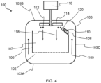
- the at least part of the air heated by the heating element 112 may be directed downwardly through the inner cooking chamber 107, as shown in FIG. 4 .
- the circulation system 114, 116 may provide mass heated air circulation within the cooking chamber 102, with both upward and downward airflow directions through the cooking chamber 102 being possible.
- the cooking appliance 100 may include an air guide member 117 arranged to guide the at least part of the heated air circulated by the circulation system 114, 116 into the inner cooking chamber 107.
- the air guide member 117 may be arranged in the duct 109.
- the air guide member 117 may assist to guide the at least part of the heated air from the duct 109 into the inner cooking chamber 107.
- the air guide member 117 may, for example, comprise a so-called star-fish shape.
- the star-fish shape comprises a plurality of radial fins which are shaped to guide the at least part of the heated air circulated by the circulation system 114, 116 into the inner cooking chamber 107.
- the circulation system 114, 116 provides an airflow 118 within the cooking chamber 102 in a direction of the viewing window 108.
- the viewing window 108 is located in an area near the cooking space in which the food is receivable in the cooking chamber 102. However, this area may be positioned, e.g. fully positioned, in a main cooking airflow path. This may mean that the viewing window 108 risks becoming polluted by particles, e.g. oil particles, carried by this airflow.
- Air speeds and directions within the cooking chamber 102 may be established from computational fluid dynamics (CFD) and laboratory analysis.
- cooking appliances 100 of the type shown in FIG. 1 in which the motor 116 rotates the fan 114 at a speed of 2650 revolutions per minute +/- 10% have been found to provide the following flow speeds: magnitude: 3.5 - 5.0 m/s; X-direction (at/proximal to the top portion 103B): 2.3 - 3.2 m/s; Y-direction (at/proximal to the top portion 103B): 1.9 - 2.8 m/s; and Z-direction (at/proximal to the top portion 103B): ⁇ 0.5 m/s.
- Values for the flow speeds may vary according to the area of interest, but the above values are considered to provide a representative insight concerning air speeds that can be provided in the area in which the viewing window 108 is located.
- air speeds provided by the circulation system 114, 116 may be in the range of 2-5 m/s.
- Flow vectors may also be established from CFD analysis.
- a "snapshot" of a dynamic process in one plane may be derived from such analysis. This may be sufficient to obtain an indication concerning the flow in the area in which the viewing window 108 is located.
- potential causes of pollution of the viewing window 108 may include: (i) "pure" airflow which sporadically transports relatively small particles close to the surface of the viewing window 108 which then adhere to this surface; (ii) the airflow coming along with an aerosol, in other words air combined with relatively sticky, e.g. oil-based, particles of various sizes, with higher temperatures of the surface of the viewing window 108 increasing the risk of such particles, e.g. oil drops, becoming stuck thereto; and (iii) fat/oil (and potentially water) mixture(s) in the cooking chamber 102 becoming sufficiently hot to "explode”, with particles being thereby driven towards the surface of the viewing window 108.
- Cause (i) may be considered to have a relatively minor influence on pollution of the viewing window 108. However, cause (ii) may have a major influence, noting that the temperature of the surface of the viewing window 108 may not be high enough to cause pyrolytic removal of particles, e.g. oil drops, that have become stuck thereto.
- cause (iii) may be highly dependent on temperatures, view-related factors and distances. For example, cause (iii) may have less influence if the heating element 112 is arranged behind a heat reflector so that the food received in the cooking chamber 102 is located in the shadow of the radiation provided by the heating element 112. However, particles arising from the above-mentioned "explosions" may likely form part of the aerosol described in relation to cause (ii).
- the cooking appliance 100 accordingly includes a flow guiding element 120 arranged in a path of the airflow 118 provided by the circulation system 114, 116 in a direction of the viewing window 108.
- the flow guiding element 120 comprises a ramp 122 arranged to displace at least part of the airflow 118 away from a plane of the viewing window 108, as denoted by the arrows 123A, and guide the at least part of the airflow 118 across the viewing window 108, as denoted by the arrow 123B.
- the ramp 122 of the flow guiding element 120 redirecting the airflow 118 away from the plane of the viewing window 108, pollution of the viewing window 108 by, in particular, aerosols generated during cooking of the food received in the cooking chamber 102 can be alleviated. Moreover, since the airflow displaced from the plane of the viewing window 108 is nonetheless guided by the ramp 122 across the viewing window 108, the flow guiding element 120 may provide minimal disruption to heated air circulation in the cooking chamber 102, and therefore may exert minimal influence over cooking of the food received in the cooking chamber 102.
- the flow guiding element 120 can be regarded as flow breaker(s) that redirect flow around the critical area in which the viewing window 108 is located, without losing/disrupting the main air frying flow. The latter may ensure that superior cooking performance is maintained in spite of the inclusion of the flow guiding element 120.
- the flow guiding element 120 may be geometrically identifiable, e.g. visible, and its effect may be measurable, e.g. by measuring air speed drop in the relevant area in which the viewing window 108 is located.
- the flow guiding element 120 can be arranged in any suitable manner provided that the flow guiding element 120 is able to redirect flow in the above-described manner.
- the flow guiding element 120 is arranged at or proximal to the top portion 103B of the cooking chamber wall 103.
- the flow guiding element 120 and the viewing window 108 may both be arranged at or proximal to the top portion 103B.
- the flow guiding element 120 may be arranged to minimize pollution of the viewing window 108 arranged in or proximal to the top portion 103B.
- the ramp 122 slopes from the top portion 103B downwardly towards the base portion 103A.
- the airflow 118 may therefore be guided downwardly by the ramp 122 towards the base portion 103A of the cooking chamber 102, and thus away from the viewing window 108, e.g. away from the viewing window 108 arranged in the top portion 103B.
- the airflow 118 may be provided along an interior surface 124 delimiting, or arranged within, the cooking chamber 102.
- the airflow 118 may be a surface airflow 118 provided along such an interior surface 124.
- the interior surface 124 is included in a surface of the cooking chamber wall 103 that delimits the cooking chamber 102.
- the interior surface 124 may be included in a surface, e.g. the inner surface, of the partition wall 106.
- the air guide member 117 may be arranged to guide the airflow 118 along the interior surface 124, e.g. the inner surface of the partition wall 106.
- the air guide member 117 e.g. star fish-type air guide member 117, may be arranged to provide a rotational component to the airflow 118, such that the path of the airflow 118 winds around the interior surface 124.
- This rotational component may be provided in addition to the airflow's 118 traversing of the height of the inner cooking chamber 107.
- the flow guiding element 120 comprises a protrusion that protrudes from the interior surface 124 along which the airflow 118 is provided.
- Such a protrusion may provide a relatively straightforward and effective way of implementing the flow guiding element 120, for example relative to alternative solutions involving a ramp-comprising recess defined in the interior surface 124.
- the ramp 122 extends in the direction of the viewing window 108 to a point that is spaced apart from the viewing window 108 along an axis A1 extending normal to the viewing window 108.
- the ramp 122 may extend to a height H that is different from that of the plane of the viewing window 108, thereby facilitating displacement of the airflow 118 away from the plane of the viewing window 108 and across the viewing window 108.
- the flow guiding element 120 may comprise a defined edge 125 at which extension of the ramp 122, e.g. from the interior surface 124, in the direction of the viewing window 108 terminates. Such a defined, e.g. sharp, edge 125 may assist to ensure that the airflow 123A initially guided up the ramp 122 is directed by the flow guiding element 120 across, rather than back towards, the viewing window 108.
- the flow guiding element 120 is arranged to guide a portion 126A, 126B of the airflow 118, e.g. passing along the interior surface 124, laterally around the viewing window 108.
- Such lateral guiding of the airflow 118 around the viewing window 108 may assist to minimize disruption caused by the flow guiding element 120 to heated air circulation in the cooking chamber 102, and may thus assist to minimize the flow guiding element's 120 influence over cooking of the food received in the cooking chamber 102.
- the part of the airflow 118 denoted by the arrow 126C in FIG. 5B corresponds to the above-described part of the airflow 118 that is displaced by the ramp 122 away from the plane of the viewing window 108 and guided across the viewing window 108.
- the flow guiding element 120 comprises sides S1, S2 that face in directions transverse to the airflow 118, with one or both of the sides S 1, S2 being connected to a base of the ramp 122 via a curved portion CP1, CP2 that curvedly extends from the ramp 122 around to the respective side S1, S2.
- Such curved portion(s) CP1, CP2 may assist the flow guiding element 120 to guide the portion 126A, 126B of the airflow laterally around the viewing window 108, as denoted in FIG. 5B by the arrows 127A, 127B.
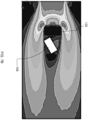
- FIG. 6 shows CFD simulated airflows proximal to a viewing window 108, whose location is indicated by the arrow 128, when a spherical flow guiding element 120 is arranged adjacent to the viewing window 108.
- This CFD simulation was constructed using an idealized space, with an inlet flow of 5 m/s being applied that enters the air space from the left in the +X direction (from left to right).
- the spherical flow guiding element 120 which has a diameter of 20 mm in this non-limiting example, was found to lower the airflow speed near the viewing window 108 to 1-2 m/s compared to 3.5 - 5 m/s when no flow guiding element 120 is employed. This represents an improvement of around a factor of two, which may translate into two times less particulate matter being deposited on the surface of viewing window 108 over time.
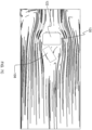
- FIGs. 7A to 7C show CFD simulated airflows proximal to a viewing window 108 when the flow guiding element 120 shown in FIGs. 5A and 5B is arranged adjacent to the viewing window 108.
- This flow guiding element 120 design was found to be effective in casting a flow shadow in which the viewing window 108 could be located.
- the airflow speed near the viewing window 108 was less than 1 m/s, corresponding to a factor of five improvement relative to the scenario in which no flow guiding element 120 is employed.
- FIG. 7A in common with FIG. 6 , illustrates displacement of at least part of the airflow 118 away from a plane of the viewing window 108 and guiding of the at least part of the airflow 118 across the viewing window 108.
- FIGs. 7B and 7C illustrate guiding of a portion 126A, 126B of the airflow 118, e.g. passing along the interior surface 124, laterally around the viewing window 108, as described above with reference to FIG. 5B .
- the viewing window 108 can be protected from the airflow 118, or at least local flow proximal to the viewing window 108 can be markedly reduced, by flow redirection via the flow guiding element 120. In this way, accumulation of pollution on the viewing window 108 over time can be minimized or prevented.
- flow guiding elements 120 shown in FIGs. 6 and 7A to 7C are provided merely as illustrative non-limiting examples, and the specific shape/form, curvatures, and dimensions of the flow guiding element 120 may vary, e.g. according to the particular architecture of the cooking appliance 100 in which the flow guiding element 120 is to be incorporated.
- the flow guiding element 120 comprises, e.g. is in the form of, a protrusion that extends at least partly around the viewing window 108, for example with the ramp 122 also extending at least partly around the viewing window 108.
- the protrusion may displace air flowing from various directions towards the viewing window 108 away from the plane of the viewing window 108, and across the viewing window 108.
- the protrusion may, for example, delimit a hole, e.g. a frustroconical hole, through which light passes to reach the viewing window 108.
- the protrusion may be detachable from the interior surface 124.
- the viewing window 108 is arranged in the top portion 103B, and in particular in the heat reflector.
- This positioning of the viewing window 108, as well as facilitating image capture of food within the cooking chamber 102, may assist to protect the image sensor 110 from the heat within the cooking chamber 102.
- the flow guiding element 120 may be arranged at or proximal to the top portion 103B, and in particular at or proximal to the heat reflector.
- the flow guiding element 120 may be arranged at a corner of the top portion 103B, e.g. heat reflector.
- This corner-positioning of the flow guiding element 120 may facilitate design of the flow guiding element 120, e.g. with appropriate dimensions, curvatures, etc., to provide enhanced redirection of the airflow 118 away from the viewing window 108.
- corner positioning of the flow guiding element 120 may reflect that in practice, e.g. in a real cooking appliance 100 architecture, the viewing window 108 and the image sensor 110 may be ideally positioned at or proximal to the top portion 103B, e.g. heat reflector, to facilitate imaging of the cooking space by the image sensor 110.
Landscapes
- Engineering & Computer Science (AREA)
- Chemical & Material Sciences (AREA)
- Combustion & Propulsion (AREA)
- Mechanical Engineering (AREA)
- General Engineering & Computer Science (AREA)
- Food Science & Technology (AREA)
- Baking, Grill, Roasting (AREA)
Abstract
Provided is a cooking appliance (100) comprising a cooking chamber (102), a heating element (112), and a circulation system (114, 116) arranged to circulate air heated by the heating element in the cooking chamber. The circulation system provides an airflow (118) within the cooking chamber, e.g. along an interior surface (124) delimiting, or arranged within, the cooking chamber. The cooking appliance further comprises a viewing window (108) towards which the airflow is directed, and an image sensor (110) arranged to enable image capture of food received in the cooking chamber through the viewing window. A flow guiding element (120) is arranged in a path of the airflow. The flow guiding element comprises a ramp arranged to displace at least part of the airflow away from the viewing window, e.g. away from a plane of the viewing window, and guide the at least part of the airflow across the viewing window.
Description
- This invention relates to a cooking appliance having a viewing window for enabling an image sensor to capture images of food being cooked in the cooking appliance through the viewing window.
- Various different types of cooking appliance are known, such as table-top cooking appliances that are positionable by the consumer on a table-top or kitchen countertop.
- One type of table-top cooking appliance is the air fryer. Air fryers are already common kitchen appliances but their popularity continues to grow. Air fryers may, for example, take the form of portable ovens which are designed to fit on a kitchen work surface.
- Air fryers can be distinguished from conventional convection ovens at least partly by the direction of air circulation through the cooking chamber. The air fryer's cooking chamber has, when orientated for use, a top and a bottom. A circulation system, e.g. in the form of a fan driven by a motor, is arranged to circulate air upwardly through food received in the cooking chamber in the direction of the top and/or downwardly through food received in the cooking chamber in the direction of the bottom.
- By, for instance, mounting the air fryer's heating element proximal to the top of cooking chamber, air having passed upwardly through the food can be reheated by the heating element before being passed around a duct and being introduced back into the food at the bottom. Such an arrangement has various advantages, particularly in terms of the frying effect which can be achieved with no or only a relatively small amount of cooking oil being required.
- Another type of table-top cooking appliance is the so-called air cooker, whose circulation system may be arranged to circulate air laterally, e.g. horizontally, across and through food received in the cooking chamber, with the air being laterally directed towards a side portion of the cooking chamber.
- Including an image sensor in a cooking appliance, such as an air fryer or air cooker, can play an important role in smart assisted cooking. For example, a food type can be recognized by food image recognition and a cooking setting can be determined based on food image analysis. Moreover, food images can be used for cooking process control, browning control, remote monitoring, burning prevention, and content for social media sharing.
- Other applications of image sensors in cooking appliances include capturing images and/or video for identification of food amount, e.g. volume, food distribution within the cooking chamber, and doneness level.
- However, the relatively rapid airflow in cooking appliances having circulation systems, and in air fryers in particular, together with aerosols generated during cooking, can cause rapid pollution of a viewing window, in other words viewport, through which the image sensor captures images of the food received in the cooking chamber.
- Such pollution can mean that algorithms, e.g. trained algorithms, employed to derive the above-mentioned food-related information from image(s) of the food may be unable to function reliably. In the worst case, the viewing window may be polluted to such an extent that even capturing an image of the cooking chamber through the viewing window is precluded.
- One possible option for removing pollution from the viewing window is pyrolytic cleaning. However, this relies on exposing the viewing window to relatively high temperatures which may not be attainable using the heating system of typical cooking appliances, and especially table-top cooking appliances, such as air fryers and air cookers. Moreover, such high temperatures could risk damaging the image sensor.
- Other potential solutions, such as detachably mounting the viewing window to facilitate cleaning and/or replacement of the viewing window, may be inconvenient for the user and costly to implement.
- The invention is defined by the claims.
- According to examples in accordance with an aspect of the invention, there is provided a cooking appliance comprising: a cooking chamber; a heating element; a viewing window; an image sensor arranged to enable image capture of food received in the cooking chamber through the viewing window; a circulation system arranged to circulate air heated by the heating element in the cooking chamber; and a flow guiding element arranged in a path of an airflow provided by the circulation system in a direction of the viewing window, the flow guiding element comprising a ramp arranged to displace at least part of the airflow away from the viewing window and guide said at least part of the airflow across the viewing window.
- By the ramp of the flow guiding element redirecting the airflow away from the viewing window, e.g. from a plane of the viewing window, pollution of the viewing window by, in particular, aerosols generated during cooking of the food received in the cooking chamber can be alleviated. Moreover, since the airflow displaced from the viewing window is nonetheless guided by the ramp across the viewing window, the flow guiding element may provide minimal disruption to heated air circulation in the cooking chamber, and therefore may exert minimal influence over cooking of the food received in the cooking chamber.
- The term "plane of the viewing window" as used herein may refer to a plane of a planar surface of the viewing window, e.g. that is exposed to the interior of the cooking chamber. Alternatively, the term "plane of the viewing window" may refer to a plane that is tangential to a non-planar surface of the viewing window, e.g. that is exposed to the interior of the cooking chamber.
- Such a tangential plane may, for example, extend perpendicular to a normal extending through a center of the viewing window.
- Thus, the term "plane of the viewing window" is not intended to refer only to planar viewing windows. In some embodiments, the viewing window is non-planar, e.g. having a non-planar surface.
- Examples of non-planar viewing windows may include viewing windows having a curved contour, e.g. a convex surface.
- Such a non-planar viewing window may, for example, be a lens, e.g. provided in addition to a lens included in the image sensor arranged behind the viewing window.
- It is generally noted that the airflow may be provided along an interior surface delimiting, or arranged within, the cooking chamber.
- In other words, the airflow may be a surface airflow provided along such an interior surface.
- In some embodiments, the interior surface is included in a surface of the cooking chamber wall that delimits the cooking chamber. Alternatively, the interior surface may be included in a surface of a partition wall arranged in the cooking chamber.
- In some embodiments, the flow guiding element comprises a protrusion that protrudes from the interior surface along which the airflow is provided.
- Such a protrusion may provide a relatively straightforward and effective way of implementing the flow guiding element, for example relative to alternative solutions involving a ramp-comprising recess defined in the interior surface.
- In some embodiments, the protrusion extends at least partly around the viewing window, for example with the ramp also extending at least partly around the viewing window.
- In such embodiments, the protrusion may displace air flowing from various directions towards the viewing window away from the plane of the viewing window, and across the viewing window.
- The protrusion may, for example, delimit a hole, e.g. a frustroconical hole, through which light passes to reach the viewing window.
- In some embodiments, the protrusion is detachable from the interior surface.
- This may assist with cleaning the viewing window (as well as the protrusion itself), particularly in embodiments in which the protrusion extends at least partly around the viewing window.
- In some embodiments, the ramp extends in the direction of the viewing window to a point that is spaced apart from the viewing window along an axis extending normal to the viewing window. Thus, the ramp may extend to a height that is different from that of the plane of the viewing window, thereby facilitating displacement of the airflow away from the plane of the viewing window and across the viewing window.
- The flow guiding element may comprise a defined edge at which extension of the ramp in the direction of the viewing window terminates. Such a defined, e.g. sharp, edge may assist to ensure that the airflow initially guided up the ramp is directed by the flow guiding element across, rather than back towards, the viewing window.
- In some embodiments, the flow guiding element is arranged to guide a portion of the airflow, e.g. passing along the interior surface, laterally around the viewing window.
- Such lateral guiding of the airflow around the viewing window may assist to minimize disruption caused by the flow guiding element to heated air circulation in the cooking chamber, and may thus assist to minimize the flow guiding element's influence over cooking of the food received in the cooking chamber.
- In some embodiments, the flow guiding element comprises sides that face in directions transverse to the airflow, with one or both of the sides being connected to a base of the ramp via a curved portion that curvedly extends from the ramp around to the respective side.
- Such curved portion(s) may assist the flow guiding element to guide a portion of the airflow laterally around the viewing window.
- In some embodiments, the viewing window is arranged in a cooking chamber wall that at least partly delimits the cooking chamber. Alternatively, the viewing window may be arranged in the partition wall located within the cooking chamber.
- In embodiments in which the cooking appliance comprises the partition wall, and irrespective of whether or not the viewing window is arranged in the partition wall, an inner surface of the partition wall may at least partly delimit an inner cooking chamber arranged within the cooking chamber.
- A duct may be defined between the cooking chamber wall that at least partly delimits the cooking chamber and an outer surface of the partition wall.
- In such embodiments, the circulation system may be arranged to circulate at least part of the heated air around the duct, into and through the inner cooking chamber, and back into the duct, with the duct being arranged to fluidly connect a top and a bottom of the inner cooking chamber to each other such that the circulating at least part of the heated air passing through the inner cooking chamber traverses a height of the inner cooking chamber.
- By the heated air passing through the inner cooking chamber traversing a height of the inner cooking chamber, the heated air may be delivered through food received in the inner cooking chamber. This may assist to achieve frying-type cooking effect.
- In some embodiments, an air guide member is arranged to guide the at least part of the heated air circulated by the circulation system into the inner cooking chamber, and along the inner surface of the partition wall in the direction of the viewing window.
- In such embodiments, the air guide member may be arranged in the duct. Thus, the air guide member may assist to guide the at least part of the heated air from the duct into the inner cooking chamber.
- The air guide member, for example a star fish-type air guide member, may assist to provide the airflow along the interior surface in the direction of the viewing window.
- In some embodiments, the air guide member is arranged to guide the airflow along the interior surface, e.g. the inner surface of the partition wall.
- In such embodiments, the air guide member may be arranged to provide a rotational component to the airflow, such that the path of the airflow winds around the interior surface. This rotational component may be provided in addition to the airflow's traversing of the height of the inner cooking chamber.
- More generally, the cooking chamber and the circulation system may be arranged such that, when the cooking appliance is orientated for use, at least part of the heated air traverses a height of the cooking chamber.
- It is noted that upward and/or downward heated airflow through the cooking chamber may not require the partition wall, the inner cooking chamber and the duct described above. Thus, in some embodiments the partition wall, the inner cooking chamber and the duct may be omitted.
- For example, instead of the partition wall, the inner cooking chamber and the duct, the cooking appliance may include a perforate food supporting base, e.g. a mesh or grid plate, arranged or arrangeable inside the cooking chamber for supporting food. In such embodiments, mass heated air circulation within the cooking chamber may be provided, with both upward and downward airflow directions through the cooking chamber being possible.
- The cooking chamber may be at least partly delimited by a base portion, a top portion, and a side portion extending between the base portion and the top portion. It is noted that the terms "base" and "top" in this context may refer to an in-use orientation of the cooking appliance, for example when the cooking appliance is positioned on a kitchen table or countertop, with the base portion being proximal to the kitchen table or countertop, the top portion being distal with respect to the kitchen table or countertop, and the side portion upstanding from the base portion in the direction of the top portion.
- In some embodiment, the viewing window is arranged in or proximal to the top portion. Such positioning of the viewing window may facilitate capturing of images of the food received in the cooking chamber.
- The flow guiding element may be arranged at or proximal to the top portion.
- For example, the flow guiding element and the viewing window may both be arranged at or proximal to the top portion.
- Thus, the flow guiding element may be arranged to minimize pollution of the viewing window arranged in or proximal to the top portion.
- It is noted that the term "proximal to" in this context may mean that the relevant component, e.g. the flow guiding element and/or the viewing window, is arranged at/in the side portion but closer to the top portion than to the base portion.
- In some embodiments, the ramp slopes from the top portion downwardly towards the base portion. Airflow may therefore be guided downwardly by the ramp towards the base portion of the cooking chamber, and thus away from the viewing window, e.g. away from the viewing window arranged in the top portion.
- In some embodiments, the top portion comprises a heat reflector. Such a heat reflector may, among other things, assist to protect the image sensor from the heat within the cooking chamber when the viewing window is arranged in the heat reflector and/or in an upper part of the side portion.
- In some embodiments, the cooking appliance comprises a seal around the viewing window for restricting fluid passage around the viewing window towards the image sensor.
- Such a seal may assist to minimize the risk of damage to the image sensor, for example by hot air and/or steam passing between the cooking chamber wall, or the partition wall, and the viewing window.
- In at least some embodiments, the cooking appliance comprises at least one light emitter arranged to illuminate at least part of the cooking chamber through the viewing window and/or through a further window arranged adjacent to the viewing window.
- In embodiments in which the cooking appliance comprises the further window, the ramp of the flow guiding element may be arranged to displace at least part of the airflow away from the further window, e.g. a plane of the further viewing window, and guide the at least part of the airflow across the further window.
- In such embodiments, the alleviation of pollution of the viewing window and/or the further window by the flow guiding element may also assist to minimize disruption to illumination of the cooking chamber provided by the light emitter(s).
- More generally, the cooking appliance may be a domestic cooking appliance, for example a domestic cooking appliance in the form of a table-top cooking appliance.
- The cooking appliance, e.g. domestic cooking appliance, may be an oven.
- Such an oven may, for example, be a table-top oven or a built-in type oven for installation in a kitchen.
- In some embodiments, the cooking appliance is an air fryer or an air cooker.
- It is noted that the air fryer and the air cooker may be examples of table-top cooking appliances.
- When the cooking appliance is an air fryer, the circulation system may be arranged to circulate air upwardly through food received in the cooking chamber in the direction of the top portion and/or downwardly through food received in the cooking chamber in the direction of the base portion.
- When the cooking appliance is an air cooker, the circulation system may be arranged to circulate air laterally across and through food received in the cooking chamber, with the air being laterally directed towards the side portion.
- These and other aspects will be apparent from and elucidated with reference to the embodiment(s) described hereinafter.
- For a better understanding of the invention, and to show more clearly how it may be carried into effect, reference will now be made, by way of example only, to the accompanying drawings, in which:
-
FIG. 1 schematically depicts a cooking appliance according to a first example; -
FIG. 2 provides a perspective view of a cooking appliance camera assembly according to an example; -
FIGs. 3A to 3C provide various schematic views of a cooking appliance according to a second example; -
FIG. 4 schematically depicts a cooking appliance according to a third example; -
FIGs. 5A and 5B schematically illustrate airflow redirection by a flow guiding element according to an example; -
FIG. 6 shows simulated airflows proximal to a viewing window when a spherical flow guiding element is arranged adjacent to the viewing window; -
FIGs. 7A to 7C show simulated airflows proximal to a viewing window when the flow guiding element shown inFIGs. 5A and 5B is arranged adjacent to the viewing window; -
FIG. 8 schematically depicts a flow guiding element according to another example; and -
FIG. 9 provides a perspective view of a top portion of a cooking appliance according to a further example. - The invention will be described with reference to the Figures.
- It should be understood that the detailed description and specific examples, while indicating exemplary embodiments of the apparatus, systems and methods, are intended for purposes of illustration only and are not intended to limit the scope of the invention. These and other features, aspects, and advantages of the apparatus, systems and methods of the present invention will become better understood from the following description, appended claims, and accompanying drawings. It should be understood that the Figures are merely schematic and are not drawn to scale. It should also be understood that the same reference numerals are used throughout the Figures to indicate the same or similar parts.
- Provided is a cooking appliance comprising a cooking chamber, a heating element, and a circulation system arranged to circulate air heated by the heating element in the cooking chamber. The circulation system provides an airflow within the cooking chamber, e.g. along an interior surface delimiting, or arranged within, the cooking chamber. The cooking appliance further comprises a viewing window towards which the airflow is directed, and an image sensor arranged to enable image capture of food received in the cooking chamber through the viewing window. A flow guiding element is arranged in a path of the airflow. The flow guiding element comprises a ramp arranged to displace at least part of the airflow away from the viewing window, e.g. away from a plane of the viewing window, and guide the at least part of the airflow across the viewing window.
-
FIG. 1 schematically depicts acooking appliance 100 according to an example. Thecooking appliance 100 in this example is in the form of an air fryer. However, the present disclosure is more generally applicable to any type ofcooking appliance 100. - Particular mention is made of the
cooking appliance 100 being adomestic cooking appliance 100, for example adomestic cooking appliance 100 in the form of a table-top cooking appliance 100. - In some embodiments, the
cooking appliance 100 is an air cooker. It is noted that the air fryer and the air cooker may be examples of table-top cooking appliances 100. - The
cooking appliance 100 comprises acooking chamber 102 in which food (not visible) is receivable. Thecooking chamber 102 may be at least partly delimited by acooking chamber wall 103. - The
cooking chamber 102 may be at least partly delimited by abase portion 103A, atop portion 103B, and aside portion 103C extending between thebase portion 103A and thetop portion 103B. Thebase portion 103A, thetop portion 103B, and theside portion 103C may be included in, e.g. may define, thecooking chamber wall 103. - It is noted that the terms "base" and "top" in this context may refer to an in-use orientation of the
cooking appliance 100, as shown inFIG. 1 . Such an in-use orientation may be adopted, for example, when thecooking appliance 100 is positioned on a kitchen table or countertop, with thebase portion 103A being proximal to the kitchen table or countertop, thetop portion 103B being distal with respect to the kitchen table or countertop, and theside portion 103C upstanding from thebase portion 103A in the direction of thetop portion 103B. - In some embodiments, such as shown in
FIG. 1 , thecooking appliance 100 includes apartition wall 106 whose inner surface at least partly delimits aninner cooking chamber 107 arranged within thecooking chamber 102. In such embodiments, food may be received specifically within theinner cooking chamber 107. - In some embodiments, the
top portion 103B comprises a heat reflector. Such a heat reflector may, among other things, assist to protect sensitive components of thecooking appliance 100, such as control circuitry, from the heat within thecooking chamber 102. - The heat reflector may be formed from any suitable material, such as a metal or metal alloy, e.g. steel. The heat reflector is preferably formed from galvanized plate metal.
- The
cooking appliance 100 comprises aviewing window 108, whose function will be explained in more detail herein below. In some embodiments, such as shown inFIG. 1 , theviewing window 108 is arranged in thecooking chamber wall 103. For example, theviewing window 108 may be arranged in, or at least proximal to, thetop portion 103B. - In alternative embodiments, such as shown in
FIGs. 3A to 3C and4 , theviewing window 108 is arranged in thepartition wall 106, subject, of course, to thecooking appliance 100 including such apartition wall 106. - In embodiments in which the
cooking appliance 100 includes thepartition wall 106, aduct 109 may be defined between the cookingchamber wall 103 and an outer surface of thepartition wall 106. Heated air may be circulated around theduct 109, into and through theinner cooking chamber 107, and back into theduct 109. - In such embodiments, the
duct 109 may be arranged to fluidly connect a top and a bottom of theinner cooking chamber 107 to each other such that the circulating heated air passing through theinner cooking chamber 107 traverses a height of theinner cooking chamber 107. - To this end, one or
more apertures 107A may be provided in a bottom of theinner cooking chamber 107, with one ormore openings 107B being provided in the top of theinner cooking chamber 107. In such embodiments, theduct 109 may provide a fluid connection between the opening(s) 107B and the aperture(s) 107A that extends around the outer surface of thepartition wall 106. - In such embodiments, the aperture(s) 107A may be defined by apertures of a perforate food supporting base. The perforate food supporting base may be regarded as a platform on which food for cooking/baking/frying/steaming may be supported.
- In some embodiments, the
cooking appliance 100 comprises a basket whose bottom portion corresponds to the perforate food supporting base. - More generally, the
cooking chamber 102 may be arranged such that, when thecooking appliance 100 is orientated for use, at least part of the heated air traverses a height of thecooking chamber 102. - The traversing of the height of the
cooking chamber 102 may mean that the at least part of the heated air passes upwardly and/or downwardly through thecooking chamber 102. - In other words, this traversing of the height of the
cooking chamber 102 may mean upward and/or downward heated airflow through the food received in thecooking chamber 102. This may assist to provide the frying effect provided by thecooking appliance 100, e.g. air fryer. - It is noted that such upward and/or downward heated airflow through the
cooking chamber 102 may not require thepartition wall 106, theinner cooking chamber 107 and theduct 109 described above. Thus, in some embodiments thepartition wall 106, theinner cooking chamber 107 and theduct 109 may be omitted. - For example, instead of the
partition wall 106, theinner cooking chamber 107 and theduct 109, thecooking appliance 100 may include a perforate food supporting base, e.g. a mesh or grid plate, arranged or arrangeable inside thecooking chamber 102 for supporting food. In such embodiments, mass heated air circulation within thecooking chamber 102 may be provided, with both upward and downward airflow directions through thecooking chamber 102 being possible. - The
cooking appliance 100 comprises animage sensor 110 arranged to enable image capture of food received in thecooking chamber 102, e.g. received in theinner cooking chamber 107 in the case of the non-limiting examples shown inFIGs. 1 ,3A to 3C and4 , through theviewing window 108. - Such image capture may enable identification of a food type, amount, distribution and/or doneness level of the food received in the
cooking chamber 102, e.g. in theinner cooking chamber 107. - Such identification may be implemented via image analysis performed by a processing system included in the
cooking appliance 100 and/or in a processing system included in a cloud-based server and/or in an external user device, such as a smartphone or tablet computer, separate from thecooking appliance 100. - Any suitable type of
image sensor 110 may be contemplated, for example a charge coupled device (CCD)image sensor 110 or a complementary metal-oxide-semiconductor (CMOS)image sensor 110. - In at least some embodiments, the
viewing window 108 is formed of a suitable optically transmissive/transparent and thermally robust material. - The
viewing window 108 may be made of glass. - Such a
viewing window 108, e.g. aglass window 108, arranged between thecooking chamber 102, e.g. theinner cooking chamber 107, and theimage sensor 110 may assist to protect theimage sensor 110 from cooking conditions in thecooking chamber 102. - In some embodiments, the
cooking appliance 100 comprises a seal around theviewing window 108 for restricting fluid passage around theviewing window 108 towards theimage sensor 110. - Such a seal may assist to minimize the risk of damage to the
image sensor 110, for example by hot air and/or steam passing between the cookingchamber wall 103, or thepartition wall 106, and theviewing window 108. - In embodiments, such as shown in
FIG. 1 , in which thecooking appliance 100 includes thepartition wall 106, theinner cooking chamber 107 and theduct 109, theimage sensor 110 and theviewing window 108 may be arranged so that theimage sensor 110 can capture images of theinner cooking chamber 107 through theduct 109. - To this end, a gap may be defined in the
partition wall 106, through which gap theimage sensor 110 can capture images of theinner cooking chamber 107. - In at least some embodiments, and referring to
FIG. 2 , thecooking appliance 100 comprises at least one light emitter arranged to illuminate at least part of thecooking chamber 102, e.g. theinner cooking chamber 107, through theviewing window 108 and/or through afurther window 111. - Any suitable type of light emitter can be contemplated. In at least some embodiments, the at least one light emitter comprises one or more light emitting diodes.
- In embodiments, such as shown in
FIG. 2 , in which thecooking appliance 100 includes thefurther window 111, thefurther window 111 may be arranged adjacent to theviewing window 108. - The
viewing window 108 may be regarded as being included in, e.g. may be defined by, a transparent plate. Alternatively, theviewing window 108 may be included in a window assembly comprising a plurality of transparent elements. - In embodiments in which the
cooking appliance 100 comprises thefurther window 111, thefurther window 111 and theviewing window 108 may, for example, correspond to respective transparent elements included in such a window assembly. An example of this is shown inFIG. 2 . - In some embodiments, the
image sensor 110 and theviewing window 108 may be included, e.g. together with the light emitter(s) and/or thefurther window 111, if present, in a camera assembly CA. - Such a camera assembly CA may facilitate mounting of the
image sensor 110 and theviewing window 108 in thecooking appliance 100, since the camera assembly CA may define the spatial relationship between theimage sensor 110 and theviewing window 108 prior to the camera assembly CA being positioned in thecooking appliance 100. - More generally, the
cooking appliance 100 includes aheating element 112, and acirculation system heating element 112 in thecooking chamber 102. - The
heating element 112 can have any suitable design. In some embodiments, theheating element 112 comprises aresistive heating element 112. Particular mention is made of a spiralresistive heating element 112. - Air can, for example, be circulated by the
circulation system resistive heating element 112 in order to heat the air. Such coils are schematically depicted inFIGs. 1 ,3A ,3C and4 . - In at least some embodiments, the
circulation system fan 114 and amotor 116, with rotation of thefan 114 by themotor 116 causing the circulating of air. - In some embodiments, such as shown in
FIGs. 1 ,3A to 3C and4 , thecirculation system heating element 112 around theduct 109, into and through theinner cooking chamber 107, and back into theduct 109. - The at least part of the air heated by the
heating element 112 may be directed upwardly through theinner cooking chamber 107, as shown inFIGs. 1 ,3A and3C . Alternatively, the at least part of the air heated by theheating element 112 may be directed downwardly through theinner cooking chamber 107, as shown inFIG. 4 . - It is also reiterated that in alternative embodiments in which the
partition wall 106, theinner cooking chamber 107 and theduct 109 are omitted, thecirculation system cooking chamber 102, with both upward and downward airflow directions through thecooking chamber 102 being possible. - With specific reference to
FIGs. 1 and3A to 3C , thecooking appliance 100, e.g. air fryer, may include anair guide member 117 arranged to guide the at least part of the heated air circulated by thecirculation system inner cooking chamber 107. - In such embodiments, the
air guide member 117 may be arranged in theduct 109. Thus, theair guide member 117 may assist to guide the at least part of the heated air from theduct 109 into theinner cooking chamber 107. - Any suitable design may be contemplated for the
air guide member 117. Theair guide member 117 may, for example, comprise a so-called star-fish shape. The star-fish shape comprises a plurality of radial fins which are shaped to guide the at least part of the heated air circulated by thecirculation system inner cooking chamber 107. - More generally, the
circulation system airflow 118 within thecooking chamber 102 in a direction of theviewing window 108. - Due to the requirement for the
image sensor 110 to capture images of the food, theviewing window 108, in other words camera viewport, is located in an area near the cooking space in which the food is receivable in thecooking chamber 102. However, this area may be positioned, e.g. fully positioned, in a main cooking airflow path. This may mean that theviewing window 108 risks becoming polluted by particles, e.g. oil particles, carried by this airflow. - Air speeds and directions within the
cooking chamber 102 may be established from computational fluid dynamics (CFD) and laboratory analysis. - For example,
cooking appliances 100 of the type shown inFIG. 1 in which themotor 116 rotates thefan 114 at a speed of 2650 revolutions per minute +/- 10% have been found to provide the following flow speeds: magnitude: 3.5 - 5.0 m/s; X-direction (at/proximal to thetop portion 103B): 2.3 - 3.2 m/s; Y-direction (at/proximal to thetop portion 103B): 1.9 - 2.8 m/s; and Z-direction (at/proximal to thetop portion 103B): <0.5 m/s. - Values for the flow speeds may vary according to the area of interest, but the above values are considered to provide a representative insight concerning air speeds that can be provided in the area in which the
viewing window 108 is located. - In general, air speeds provided by the
circulation system - Flow vectors may also be established from CFD analysis. A "snapshot" of a dynamic process in one plane may be derived from such analysis. This may be sufficient to obtain an indication concerning the flow in the area in which the
viewing window 108 is located. - For example, focusing on the plane in which the
viewing window 108 is arranged, further insights can be obtained concerning how the air is moving. It can be observed, via splitting into X/Y/Z flow actions, that the Z-direction flow is minor compared to X-direction and Y-direction flows. Thus, airflow in the area in which theviewing window 108 is located can be approximated as a planar problem. - Moreover, potential causes of pollution of the
viewing window 108 may include: (i) "pure" airflow which sporadically transports relatively small particles close to the surface of theviewing window 108 which then adhere to this surface; (ii) the airflow coming along with an aerosol, in other words air combined with relatively sticky, e.g. oil-based, particles of various sizes, with higher temperatures of the surface of theviewing window 108 increasing the risk of such particles, e.g. oil drops, becoming stuck thereto; and (iii) fat/oil (and potentially water) mixture(s) in thecooking chamber 102 becoming sufficiently hot to "explode", with particles being thereby driven towards the surface of theviewing window 108. - Cause (i) may be considered to have a relatively minor influence on pollution of the
viewing window 108. However, cause (ii) may have a major influence, noting that the temperature of the surface of theviewing window 108 may not be high enough to cause pyrolytic removal of particles, e.g. oil drops, that have become stuck thereto. - The relative influence of cause (iii) may be highly dependent on temperatures, view-related factors and distances. For example, cause (iii) may have less influence if the
heating element 112 is arranged behind a heat reflector so that the food received in thecooking chamber 102 is located in the shadow of the radiation provided by theheating element 112. However, particles arising from the above-mentioned "explosions" may likely form part of the aerosol described in relation to cause (ii). - Referring to
FIGs. 1 ,3A to 3C ,4 ,5A and 5B , thecooking appliance 100 according to the present disclosure accordingly includes aflow guiding element 120 arranged in a path of theairflow 118 provided by thecirculation system viewing window 108. - As best shown in
FIG. 5A , theflow guiding element 120 comprises aramp 122 arranged to displace at least part of theairflow 118 away from a plane of theviewing window 108, as denoted by thearrows 123A, and guide the at least part of theairflow 118 across theviewing window 108, as denoted by thearrow 123B. - By the
ramp 122 of theflow guiding element 120 redirecting theairflow 118 away from the plane of theviewing window 108, pollution of theviewing window 108 by, in particular, aerosols generated during cooking of the food received in thecooking chamber 102 can be alleviated. Moreover, since the airflow displaced from the plane of theviewing window 108 is nonetheless guided by theramp 122 across theviewing window 108, theflow guiding element 120 may provide minimal disruption to heated air circulation in thecooking chamber 102, and therefore may exert minimal influence over cooking of the food received in thecooking chamber 102. - The
flow guiding element 120 can be regarded as flow breaker(s) that redirect flow around the critical area in which theviewing window 108 is located, without losing/disrupting the main air frying flow. The latter may ensure that superior cooking performance is maintained in spite of the inclusion of theflow guiding element 120. - It is noted that the
flow guiding element 120 may be geometrically identifiable, e.g. visible, and its effect may be measurable, e.g. by measuring air speed drop in the relevant area in which theviewing window 108 is located. - The
flow guiding element 120 can be arranged in any suitable manner provided that theflow guiding element 120 is able to redirect flow in the above-described manner. - In some embodiments, such as shown in
FIG. 1 , theflow guiding element 120 is arranged at or proximal to thetop portion 103B of thecooking chamber wall 103. For example, theflow guiding element 120 and theviewing window 108 may both be arranged at or proximal to thetop portion 103B. Thus, theflow guiding element 120 may be arranged to minimize pollution of theviewing window 108 arranged in or proximal to thetop portion 103B. - In some embodiments, such as shown in
FIG. 1 , theramp 122 slopes from thetop portion 103B downwardly towards thebase portion 103A. Theairflow 118 may therefore be guided downwardly by theramp 122 towards thebase portion 103A of thecooking chamber 102, and thus away from theviewing window 108, e.g. away from theviewing window 108 arranged in thetop portion 103B. - As a general remark, the
airflow 118 may be provided along aninterior surface 124 delimiting, or arranged within, thecooking chamber 102. In other words, theairflow 118 may be asurface airflow 118 provided along such aninterior surface 124. - In some embodiments, the
interior surface 124 is included in a surface of thecooking chamber wall 103 that delimits thecooking chamber 102. Alternatively, theinterior surface 124 may be included in a surface, e.g. the inner surface, of thepartition wall 106. - In embodiments, such as shown in
FIGs. 1 and3A to 3C , in which thecooking appliance 100 comprises theair guide member 117, theair guide member 117 may be arranged to guide theairflow 118 along theinterior surface 124, e.g. the inner surface of thepartition wall 106. - In such embodiments, and as best shown in
FIG. 3B , theair guide member 117, e.g. star fish-typeair guide member 117, may be arranged to provide a rotational component to theairflow 118, such that the path of theairflow 118 winds around theinterior surface 124. This rotational component may be provided in addition to the airflow's 118 traversing of the height of theinner cooking chamber 107. - In some embodiments, such as shown in
FIGs. 1 ,3A to 3C ,4 ,5A and 5B , theflow guiding element 120 comprises a protrusion that protrudes from theinterior surface 124 along which theairflow 118 is provided. - Such a protrusion may provide a relatively straightforward and effective way of implementing the
flow guiding element 120, for example relative to alternative solutions involving a ramp-comprising recess defined in theinterior surface 124. - In some embodiments, and referring again to
FIG. 5A , theramp 122 extends in the direction of theviewing window 108 to a point that is spaced apart from theviewing window 108 along an axis A1 extending normal to theviewing window 108. Thus, theramp 122 may extend to a height H that is different from that of the plane of theviewing window 108, thereby facilitating displacement of theairflow 118 away from the plane of theviewing window 108 and across theviewing window 108. - The
flow guiding element 120 may comprise a definededge 125 at which extension of theramp 122, e.g. from theinterior surface 124, in the direction of theviewing window 108 terminates. Such a defined, e.g. sharp,edge 125 may assist to ensure that theairflow 123A initially guided up theramp 122 is directed by theflow guiding element 120 across, rather than back towards, theviewing window 108. - In some embodiments, and referring now to
FIG. 5B , theflow guiding element 120 is arranged to guide aportion airflow 118, e.g. passing along theinterior surface 124, laterally around theviewing window 108. Such lateral guiding of theairflow 118 around theviewing window 108 may assist to minimize disruption caused by theflow guiding element 120 to heated air circulation in thecooking chamber 102, and may thus assist to minimize the flow guiding element's 120 influence over cooking of the food received in thecooking chamber 102. - It is noted that the part of the
airflow 118 denoted by thearrow 126C inFIG. 5B corresponds to the above-described part of theairflow 118 that is displaced by theramp 122 away from the plane of theviewing window 108 and guided across theviewing window 108. - In some embodiments, and still referring to
FIG. 5B , theflow guiding element 120 comprises sides S1, S2 that face in directions transverse to theairflow 118, with one or both of the sides S 1, S2 being connected to a base of theramp 122 via a curved portion CP1, CP2 that curvedly extends from theramp 122 around to the respective side S1, S2. Such curved portion(s) CP1, CP2 may assist theflow guiding element 120 to guide theportion viewing window 108, as denoted inFIG. 5B by thearrows -
FIG. 6 shows CFD simulated airflows proximal to aviewing window 108, whose location is indicated by thearrow 128, when a sphericalflow guiding element 120 is arranged adjacent to theviewing window 108. - This CFD simulation was constructed using an idealized space, with an inlet flow of 5 m/s being applied that enters the air space from the left in the +X direction (from left to right). The spherical
flow guiding element 120, which has a diameter of 20 mm in this non-limiting example, was found to lower the airflow speed near theviewing window 108 to 1-2 m/s compared to 3.5 - 5 m/s when noflow guiding element 120 is employed. This represents an improvement of around a factor of two, which may translate into two times less particulate matter being deposited on the surface ofviewing window 108 over time. -
FIGs. 7A to 7C show CFD simulated airflows proximal to aviewing window 108 when theflow guiding element 120 shown inFIGs. 5A and 5B is arranged adjacent to theviewing window 108. Thisflow guiding element 120 design was found to be effective in casting a flow shadow in which theviewing window 108 could be located. In this non-limiting example, the airflow speed near theviewing window 108 was less than 1 m/s, corresponding to a factor of five improvement relative to the scenario in which noflow guiding element 120 is employed. -
FIG. 7A , in common withFIG. 6 , illustrates displacement of at least part of theairflow 118 away from a plane of theviewing window 108 and guiding of the at least part of theairflow 118 across theviewing window 108. -
FIGs. 7B and7C illustrate guiding of aportion airflow 118, e.g. passing along theinterior surface 124, laterally around theviewing window 108, as described above with reference toFIG. 5B . - This evidence shows that the
viewing window 108 can be protected from theairflow 118, or at least local flow proximal to theviewing window 108 can be markedly reduced, by flow redirection via theflow guiding element 120. In this way, accumulation of pollution on theviewing window 108 over time can be minimized or prevented. - It is noted that the
flow guiding elements 120 shown inFIGs. 6 and7A to 7C are provided merely as illustrative non-limiting examples, and the specific shape/form, curvatures, and dimensions of theflow guiding element 120 may vary, e.g. according to the particular architecture of thecooking appliance 100 in which theflow guiding element 120 is to be incorporated. - In some embodiments, such as shown in
FIG. 8 , theflow guiding element 120 comprises, e.g. is in the form of, a protrusion that extends at least partly around theviewing window 108, for example with theramp 122 also extending at least partly around theviewing window 108. - In such embodiments, the protrusion may displace air flowing from various directions towards the
viewing window 108 away from the plane of theviewing window 108, and across theviewing window 108. - The protrusion may, for example, delimit a hole, e.g. a frustroconical hole, through which light passes to reach the
viewing window 108. - Alternatively or additionally, the protrusion may be detachable from the
interior surface 124. - This may assist with cleaning the viewing window 108 (as well as the protrusion itself), particularly in embodiments in which the protrusion extends at least partly around the
viewing window 108. - In some embodiments, such as shown in
FIGs. 1 and9 , theviewing window 108 is arranged in thetop portion 103B, and in particular in the heat reflector. - This positioning of the
viewing window 108, as well as facilitating image capture of food within thecooking chamber 102, may assist to protect theimage sensor 110 from the heat within thecooking chamber 102. - Alternatively or additionally, the
flow guiding element 120 may be arranged at or proximal to thetop portion 103B, and in particular at or proximal to the heat reflector. - In some embodiments, such as shown in
FIG. 9 , theflow guiding element 120 may be arranged at a corner of thetop portion 103B, e.g. heat reflector. - This corner-positioning of the
flow guiding element 120 may facilitate design of theflow guiding element 120, e.g. with appropriate dimensions, curvatures, etc., to provide enhanced redirection of theairflow 118 away from theviewing window 108. - Moreover, such corner positioning of the
flow guiding element 120 may reflect that in practice, e.g. in areal cooking appliance 100 architecture, theviewing window 108 and theimage sensor 110 may be ideally positioned at or proximal to thetop portion 103B, e.g. heat reflector, to facilitate imaging of the cooking space by theimage sensor 110. - Variations to the disclosed embodiments can be understood and effected by those skilled in the art in practicing the claimed invention, from a study of the drawings, the disclosure and the appended claims. In the claims, the word "comprising" does not exclude other elements or steps, and the indefinite article "a" or "an" does not exclude a plurality.
- The mere fact that certain measures are recited in mutually different dependent claims does not indicate that a combination of these measures cannot be used to advantage.
- If the term "adapted to" is used in the claims or description, it is noted the term "adapted to" is intended to be equivalent to the term "configured to".
- Any reference signs in the claims should not be construed as limiting the scope.
Claims (15)
- A cooking appliance (100) comprising:a cooking chamber (102);a heating element (112);a viewing window (108);an image sensor (110) arranged to enable image capture of food received in the cooking chamber through the viewing window;a circulation system (114, 116) arranged to circulate air heated by the heating element in the cooking chamber; anda flow guiding element (120) arranged in a path of an airflow (118) provided by the circulation system in a direction of the viewing window, the flow guiding element comprising a ramp (122) arranged to displace at least part of the airflow away from the viewing window and guide said at least part of the airflow across the viewing window.
- The cooking appliance (100) according to claim 1, wherein the flow guiding element (120) comprises a protrusion that protrudes from an interior surface (124) along which the airflow (118) is provided; optionally wherein the protrusion extends at least partly around the viewing window (108).
- The cooking appliance (100) according to claim 1 or claim 2, wherein the ramp (122) extends in the direction of the viewing window (108) to a point (125) that is spaced apart from the viewing window along an axis (A1) extending normal to the viewing window.
- The cooking appliance (100) according to any one of claims 1 to 3, wherein the flow guiding element (120) comprises a defined edge at which extension of the ramp (122) in the direction of the viewing window (108) terminates.
- The cooking appliance (100) according to any one of claims 1 to 4, wherein the flow guiding element (120) is arranged to guide a portion of the airflow (118) laterally around the viewing window (108).
- The cooking appliance (100) according to claim 5, wherein the flow guiding element (120) comprises sides (S1, S2) that face in directions transverse to the airflow (118), wherein one or both of the sides are connected to a base of the ramp (122) via a curved portion (CP1, CP2) that curvedly extends from the ramp around to the respective side.
- The cooking appliance (100) according to any one of claims 1 to 6, wherein the viewing window (108) is arranged in a cooking chamber wall (103) that at least partly delimits the cooking chamber (102) or is arranged in a partition wall (106) located within the cooking chamber.
- The cooking appliance (100) according to claim 7, wherein an inner surface of the partition wall (106) at least partly delimits an inner cooking chamber (107) arranged within the cooking chamber (102), a duct (109) being defined between the cooking chamber wall (103) and an outer surface of the partition wall, wherein the circulation system (114, 116) is arranged to circulate at least part of the heated air around the duct, into and through the inner cooking chamber, and back into the duct, the duct being arranged to fluidly connect a top and a bottom of the inner cooking chamber to each other such that the circulating at least part of the heated air passing through the inner cooking chamber traverses a height of the inner cooking chamber.
- The cooking appliance (100) according to claim 8, comprising an air guide member (117) arranged to guide the at least part of the heated air circulated by the circulation system (114, 116) into the inner cooking chamber (107), and along the inner surface of the partition wall (106) in the direction of the viewing window (108).
- The cooking appliance (100) according to claim 9, wherein the air guide member (117) is arranged in the duct (109).
- The cooking appliance (100) according to any one of claims 1 to 10, wherein the cooking chamber (102) is at least partly delimited by a base portion (103A), a top portion (103B), and a side portion (103C) extending between the base portion and the top portion, wherein the viewing window (108) is arranged in or proximal to the top portion.
- The cooking appliance (100) according to claim 11, wherein the flow guiding element (120) is arranged at or proximal to the top portion (103B).
- The cooking appliance (100) according to claim 11 or claim 12, wherein the ramp (122) slopes from the top portion (103B) downwardly towards the base portion (103A).
- The cooking appliance (100) according to any one of claims 11 to 13, wherein the top portion (103B) comprises a heat reflector.
- The cooking appliance (100) according to any one of claims 1 to 14, comprising at least one light emitter arranged to illuminate at least part of the cooking chamber (102) through the viewing window (108) and/or through a further window (111) arranged adjacent to the viewing window.
Priority Applications (8)
| Application Number | Priority Date | Filing Date | Title |
|---|---|---|---|
| EP23172123.4A EP4461173A1 (en) | 2023-05-08 | 2023-05-08 | Cooking appliance comprising viewing window and image sensor for capturing images through the viewing window |
| EP24714510.5A EP4478921B1 (en) | 2023-05-08 | 2024-03-29 | Cooking appliance comprising viewing window and image sensor for capturing images through the viewing window |
| PL24714510.5T PL4478921T3 (en) | 2023-05-08 | 2024-03-29 | Cooking appliance comprising viewing window and image sensor for capturing images through the viewing window |
| AU2024205596A AU2024205596B2 (en) | 2023-05-08 | 2024-03-29 | Cooking appliance comprising viewing window and image sensor for capturing images through the viewing window |
| CN202480001799.8A CN118843410B (en) | 2023-05-08 | 2024-03-29 | Cooking appliance including a viewing window and an image sensor for capturing an image through the viewing window |
| KR1020247030563A KR102788928B1 (en) | 2023-05-08 | 2024-03-29 | A cooking device comprising an observation window and an image sensor for capturing images through the observation window. |
| PCT/EP2024/058794 WO2024230987A1 (en) | 2023-05-08 | 2024-03-29 | Cooking appliance comprising viewing window and image sensor for capturing images through the viewing window |
| US19/129,710 US20260009544A1 (en) | 2023-05-08 | 2024-03-29 | Cooking appliance comprising viewing window and image sensor for capturing images through the viewing window |
Applications Claiming Priority (1)
| Application Number | Priority Date | Filing Date | Title |
|---|---|---|---|
| EP23172123.4A EP4461173A1 (en) | 2023-05-08 | 2023-05-08 | Cooking appliance comprising viewing window and image sensor for capturing images through the viewing window |
Publications (1)
| Publication Number | Publication Date |
|---|---|
| EP4461173A1 true EP4461173A1 (en) | 2024-11-13 |
Family
ID=86330542
Family Applications (1)
| Application Number | Title | Priority Date | Filing Date |
|---|---|---|---|
| EP23172123.4A Withdrawn EP4461173A1 (en) | 2023-05-08 | 2023-05-08 | Cooking appliance comprising viewing window and image sensor for capturing images through the viewing window |
Country Status (2)
| Country | Link |
|---|---|
| EP (1) | EP4461173A1 (en) |
| WO (1) | WO2024230987A1 (en) |
Citations (3)
| Publication number | Priority date | Publication date | Assignee | Title |
|---|---|---|---|---|
| DE102020108572A1 (en) * | 2020-03-27 | 2021-09-30 | Rational Aktiengesellschaft | Cooking device with optics |
| WO2022078839A1 (en) * | 2020-10-14 | 2022-04-21 | Miele & Cie. Kg | Method for determining the time for cleaning a cooking chamber of a cooking appliance |
| US20220202236A1 (en) * | 2019-07-05 | 2022-06-30 | Koninklijke Philips N.V. | A cooking device and cooking method |
-
2023
- 2023-05-08 EP EP23172123.4A patent/EP4461173A1/en not_active Withdrawn
-
2024
- 2024-03-29 WO PCT/EP2024/058794 patent/WO2024230987A1/en not_active Ceased
Patent Citations (3)
| Publication number | Priority date | Publication date | Assignee | Title |
|---|---|---|---|---|
| US20220202236A1 (en) * | 2019-07-05 | 2022-06-30 | Koninklijke Philips N.V. | A cooking device and cooking method |
| DE102020108572A1 (en) * | 2020-03-27 | 2021-09-30 | Rational Aktiengesellschaft | Cooking device with optics |
| WO2022078839A1 (en) * | 2020-10-14 | 2022-04-21 | Miele & Cie. Kg | Method for determining the time for cleaning a cooking chamber of a cooking appliance |
Also Published As
| Publication number | Publication date |
|---|---|
| WO2024230987A1 (en) | 2024-11-14 |
Similar Documents
| Publication | Publication Date | Title |
|---|---|---|
| JP6416892B2 (en) | Air flyer | |
| JP2016519993A (en) | Air based flyer | |
| JP2016519992A5 (en) | ||
| CN109414137B (en) | Air fryer | |
| TW201825836A (en) | Range hood | |
| JP6450748B2 (en) | Air fry equipment | |
| CN113163984B (en) | Contact oven with passive smoke abatement | |
| CN113795182B (en) | Cooking appliance with sensor unit arranged outside the cooking chamber | |
| CN106580120A (en) | Oven capable of collecting food images | |
| KR102411279B1 (en) | Cooking Pot with Exhaust Hood | |
| EP4478921B1 (en) | Cooking appliance comprising viewing window and image sensor for capturing images through the viewing window | |
| US20230389750A1 (en) | Domestic kitchen apparatus | |
| WO2024230987A1 (en) | Cooking appliance comprising viewing window and image sensor for capturing images through the viewing window | |
| EP4309550A1 (en) | Air fryer comprising a camera assembly | |
| TWI724879B (en) | Image capturing module and food processing device comprising the same | |
| CN210493796U (en) | Multifunctional gas oven | |
| US20230371739A1 (en) | Assisted cooking | |
| CN121647518A (en) | Cooking apparatus | |
| EP4411247A1 (en) | Heating cooker | |
| KR20260038032A (en) | Cooking apparatus | |
| CN121647519A (en) | Cooking apparatus | |
| EP4066703A1 (en) | Domestic kitchen apparatus | |
| KR20250051190A (en) | Hood | |
| JP2002010922A (en) | Roaster | |
| CN121843627A (en) | Air fryer with air flow guide |
Legal Events
| Date | Code | Title | Description |
|---|---|---|---|
| PUAI | Public reference made under article 153(3) epc to a published international application that has entered the european phase |
Free format text: ORIGINAL CODE: 0009012 |
|
| STAA | Information on the status of an ep patent application or granted ep patent |
Free format text: STATUS: THE APPLICATION HAS BEEN PUBLISHED |
|
| AK | Designated contracting states |
Kind code of ref document: A1 Designated state(s): AL AT BE BG CH CY CZ DE DK EE ES FI FR GB GR HR HU IE IS IT LI LT LU LV MC ME MK MT NL NO PL PT RO RS SE SI SK SM TR |
|
| STAA | Information on the status of an ep patent application or granted ep patent |
Free format text: STATUS: THE APPLICATION IS DEEMED TO BE WITHDRAWN |
|
| 18D | Application deemed to be withdrawn |
Effective date: 20250514 |