EP4460133A2 - Verfahren und systeme zur downlink-übertragung und zwischenzeilen-uplink-übertragung - Google Patents
Verfahren und systeme zur downlink-übertragung und zwischenzeilen-uplink-übertragung Download PDFInfo
- Publication number
- EP4460133A2 EP4460133A2 EP24201225.0A EP24201225A EP4460133A2 EP 4460133 A2 EP4460133 A2 EP 4460133A2 EP 24201225 A EP24201225 A EP 24201225A EP 4460133 A2 EP4460133 A2 EP 4460133A2
- Authority
- EP
- European Patent Office
- Prior art keywords
- base station
- interlace
- dci
- aspects
- pucch
- Prior art date
- Legal status (The legal status is an assumption and is not a legal conclusion. Google has not performed a legal analysis and makes no representation as to the accuracy of the status listed.)
- Pending
Links
- 238000000034 method Methods 0.000 title claims description 111
- 230000005540 biological transmission Effects 0.000 title description 70
- 235000019527 sweetened beverage Nutrition 0.000 claims abstract 31
- 230000001174 ascending effect Effects 0.000 claims description 3
- 238000013468 resource allocation Methods 0.000 description 194
- 230000007246 mechanism Effects 0.000 description 30
- 230000011664 signaling Effects 0.000 description 27
- 238000013507 mapping Methods 0.000 description 24
- 238000004891 communication Methods 0.000 description 23
- 125000004122 cyclic group Chemical group 0.000 description 16
- 230000001413 cellular effect Effects 0.000 description 5
- 238000013461 design Methods 0.000 description 5
- 230000004044 response Effects 0.000 description 5
- 238000013459 approach Methods 0.000 description 4
- 230000006870 function Effects 0.000 description 4
- 238000005259 measurement Methods 0.000 description 4
- 238000012545 processing Methods 0.000 description 4
- 230000001351 cycling effect Effects 0.000 description 3
- 238000001228 spectrum Methods 0.000 description 3
- 238000004590 computer program Methods 0.000 description 2
- 238000010586 diagram Methods 0.000 description 2
- 238000005516 engineering process Methods 0.000 description 2
- 238000004519 manufacturing process Methods 0.000 description 2
- 230000003287 optical effect Effects 0.000 description 2
- 201000000913 Duane retraction syndrome Diseases 0.000 description 1
- 229920000776 Poly(Adenosine diphosphate-ribose) polymerase Polymers 0.000 description 1
- 239000000872 buffer Substances 0.000 description 1
- 238000013500 data storage Methods 0.000 description 1
- 238000000162 direct recoil spectroscopy Methods 0.000 description 1
- 230000007774 longterm Effects 0.000 description 1
- 238000007726 management method Methods 0.000 description 1
- 238000012986 modification Methods 0.000 description 1
- 230000004048 modification Effects 0.000 description 1
- 230000010363 phase shift Effects 0.000 description 1
- 230000008569 process Effects 0.000 description 1
- 238000012546 transfer Methods 0.000 description 1
Images


Classifications
-
- H—ELECTRICITY
- H04—ELECTRIC COMMUNICATION TECHNIQUE
- H04W—WIRELESS COMMUNICATION NETWORKS
- H04W56/00—Synchronisation arrangements
- H04W56/001—Synchronization between nodes
- H04W56/0015—Synchronization between nodes one node acting as a reference for the others
-
- H—ELECTRICITY
- H04—ELECTRIC COMMUNICATION TECHNIQUE
- H04W—WIRELESS COMMUNICATION NETWORKS
- H04W72/00—Local resource management
- H04W72/04—Wireless resource allocation
-
- H—ELECTRICITY
- H04—ELECTRIC COMMUNICATION TECHNIQUE
- H04W—WIRELESS COMMUNICATION NETWORKS
- H04W74/00—Wireless channel access
- H04W74/08—Non-scheduled access, e.g. ALOHA
- H04W74/0808—Non-scheduled access, e.g. ALOHA using carrier sensing, e.g. carrier sense multiple access [CSMA]
Definitions
- the described aspects generally relate downlink transmission and interlace uplink transmission in wireless communications.
- some aspects of this disclosure relate to designs for resource mapping for operation with shared spectrum channel access.
- Some aspects of this disclosure relate to designs for resource allocation for interlace uplink transmissions.
- a user equipment (UE) communicating with a base station (for example, an evolved Node B (eNB), a next generation Node B (gNB)) over a communication link can use an uplink control channel to transmit control and measurement information to the base station and can use an uplink data channel to transmit data to the base station.
- the base station can use a downlink control channel to transmit control information to the UE on how to use resources on the uplink channel(s).
- Some aspects of this disclosure relate to apparatuses and methods for implementing downlink transmission and interlace uplink transmission for 3rd Generation Partnership Project (3GPP) release 15 (Rel-15), release 16 (Rel-16), Rel-16 New Radio (NR), and/or Rel-16 NR-U (New Radio Unlicensed).
- 3GPP 3rd Generation Partnership Project
- the base station includes a transceiver configured to communicate over a wireless network with a user equipment (UE) and a processor communicatively coupled to the transceiver.
- the processor divides a plurality of candidate Synchronization Signal Block (SSB) positions in a time window into a plurality of groups and communicates, using the transceiver, information associated with the plurality of groups of candidate SSB positions to the UE.
- the processor further performs a listen-before-talk (LBT) procedure. In response to the LBT procedure being successful, the processor determines a first group of the plurality of groups and transmits, using the transceiver, one or more SSBs on one or more candidate SSB positions of the first group to the UE.
- LBT listen-before-talk
- the processor is configured to communicate, using the transceiver, the information associated with the plurality of groups of candidate SSB positions to the UE using at least one of a Master Information Block (MIB), a payload of a Physical Broadcast Channel (PBCH), or a System Information Block 1 (SIB 1).
- MIB Master Information Block
- PBCH Physical Broadcast Channel
- SIB System Information Block 1
- the processor is configured to communicate, using the transceiver, the information associated with the plurality of groups of candidate SSB positions to the UE using ssb-PositionsInBurst information element (IE) in the SIB 1.
- IE ssb-PositionsInBurst information element
- each bit in the ssb-PositionsInBurst IE corresponds to one of the plurality of groups.
- the processor is configured to transmit, using the transceiver, the one or more SSBs on the one or more candidate SSB positions of the first group during a Discovery Reference Signal (DRS) window.
- DRS Discovery Reference Signal
- the information associated with the plurality of groups of candidate SSB positions comprises a parameter and a number of the plurality of candidate SSB positions. In some examples, the number of the plurality of candidate SSB positions is 20.
- the method includes dividing a plurality of candidate Synchronization Signal Block (SSB) positions in a time window into a plurality of groups and communicating information associated with the plurality of groups of candidate SSB positions to a user equipment (UE).
- the method further includes performing a listen-before-talk (LBT) procedure.
- LBT listen-before-talk
- the method includes determining a first group of the plurality of groups and transmitting one or more SSBs on one or more candidate SSB positions of the first group to the UE.
- Some aspects of this disclosure relate to a non-transitory computer-readable medium storing instructions.
- the instructions When the instructions are executed by a processor of a base station, the instructions cause the processor to perform operations including dividing a plurality of candidate Synchronization Signal Block (SSB) positions in a time window into a plurality of groups and communicating information associated with the plurality of groups of candidate SSB positions to a user equipment (UE).
- the operations further include performing a listen-before-talk (LBT) procedure.
- LBT listen-before-talk
- the operations include determining a first group of the plurality of groups and transmitting one or more SSBs on one or more candidate SSB positions of the first group to the UE.
- the UE includes a transceiver configured to communicate over a wireless network with a base station and a processor communicatively coupled to the transceiver.
- the processor receives, using the transceiver and from the base station, information associated with a plurality of groups of candidate Synchronization Signal Block (SSB) positions.
- the processor further receives, using the transceiver and from the base station, an SSB at a first group of candidate SSB positions and determine that the first group of candidate SSB positions is used for receiving SSBs.
- SSB Synchronization Signal Block
- the method includes receiving, from a base station, information associated with a plurality of groups of candidate Synchronization Signal Block (SSB) positions.
- the method further includes receiving, from the base station, an SSB at a first group of candidate SSB positions and determining that the first group of candidate SSB positions is used for receiving SSBs.
- SSB Synchronization Signal Block
- Some aspects of this disclosure relate to a non-transitory computer-readable medium storing instructions.
- the instructions When the instructions are executed by a processor of a user equipment (UE), the instructions cause the processor to perform operations including receiving, from a base station, information associated with a plurality of groups of candidate Synchronization Signal Block (SSB) positions.
- the operations further include receiving, from the base station, an SSB at a first group of candidate SSB positions and determining that the first group of candidate SSB positions is used for receiving SSBs.
- SSB Synchronization Signal Block
- the base station includes a transceiver configured to communicate over a wireless network with a user equipment (UE) and a processor communicatively coupled to the transceiver.
- the processor generates a Downlink Channel Indicator (DCI).
- DCI includes interlace resource allocation information for a Physical Uplink Control Channel (PUCCH).
- the processor using the transceiver, transmits the DCI to the UE.
- PUCCH Physical Uplink Control Channel
- the interlace resource allocation information for the PUCCH includes a bitmap, where a first value of a bit of the bitmap indicates that a corresponding interlace is allocated for the PUCCH.
- a size of the bitmap is based on a sub-carrier spacing of the PUCCH.
- the interlace resource allocation information includes a first interlace index and a second interlace index is calculated by the UE using the first interlace index.
- the second interlace index is based on the first interlace index and a number of interlaces for a sub-carrier spacing of the PUCCH.
- the PUCCH is at least one of PUCCH Format 2 or PUCCH Format 3.
- the DCI further includes a mapping between Orthogonal Cover Code (OCC) index applied on an Uplink Control Information (UCI) symbol and a cyclic shift applied to a DeModulation Reference Signal (DMRS) symbol.
- OCC Orthogonal Cover Code
- the DCI further includes information for the UE to use a plurality of Orthogonal Cover Code (OCC) indices and to cycle the plurality of OCC indices across Physical Resource Blocks (PRBs) within an interlace.
- OCC Orthogonal Cover Code
- the DCI further includes information for the UE to apply a scrambling sequence per transmission to one or more symbols associated with the PUCCH.
- the processor is further configured to generate System Information Block 1 (SIB1), the SIB1 comprises a value configured to signal interlaced cell-specific PUCCH resource allocation to the UE.
- SIB1 System Information Block 1
- the method includes generating a Downlink Channel Indicator (DCI).
- the DCI includes interlace resource allocation information for a Physical Uplink Control Channel (PUCCH).
- the method further includes transmitting the DCI to the UE.
- DCI Downlink Channel Indicator
- PUCCH Physical Uplink Control Channel
- Some aspects of this disclosure relate to a non-transitory computer-readable medium storing instructions.
- the instructions When the instructions are executed by a processor of a base station, the instructions cause the processor to perform operations including generating a Downlink Channel Indicator (DCI).
- the DCI includes interlace resource allocation information for a Physical Uplink Control Channel (PUCCH).
- the operations further include transmitting the DCI to the UE.
- DCI Downlink Channel Indicator
- PUCCH Physical Uplink Control Channel
- the UE includes a transceiver configured to communicate over a wireless network with a base station and a processor communicatively coupled to the transceiver.
- the processor receives, from a base station, a Downlink Channel Indicator (DCI).
- DCI includes interlace resource allocation information for a Physical Uplink Control Channel (PUCCH).
- the processor further allocates resources on the PUCCH based on the interlace resource allocation information.
- PUCCH Physical Uplink Control Channel
- the interlace resource allocation information for the PUCCH include a bitmap.
- a first value of a bit of the bitmap indicates that a corresponding interlace is allocated for the PUCCH.
- the interlace resource allocation information include a first interlace index.
- the processor is further configured to calculate a second interlace index using the first interlace index.
- the processor is configured to calculate the second interlace index based on the first interlace index and a number of interlaces for a sub-carrier spacing of the PUCCH.
- the DCI further includes a mapping between Orthogonal Cover Code (OCC) index applied on an Uplink Control Information (UCI) symbol and a cyclic shift (CS) applied to a DeModulation Reference Signal (DMRS) symbol.
- OCC Orthogonal Cover Code
- the processor is further configured to use the OCC Index to determine a CS index, generate the UCI symbol using the OCC index, and generate the DRMS symbol using the CS Index.
- the processor is further configured to determine a plurality of Orthogonal Cover Code (OCC) indices based on the received DCI and cycle the plurality of OCC indices across Physical Resource Blocks (PRBs) within an interlace.
- OCC Orthogonal Cover Code
- the processor is further configured to apply, based on the received DCI, a scrambling sequence per transmission to one or more symbols associated with the PUCCH.
- the processor is further configured to receive System Information Block 1 (SIB1), wherein the SIB1 comprises a value configured to signal interlaced cell-specific PUCCH resource allocation to the UE.
- SIB1 comprises a value configured to signal interlaced cell-specific PUCCH resource allocation to the UE.
- the method includes receiving, from a base station, a Downlink Channel Indicator (DCI).
- DCI includes interlace resource allocation information for a Physical Uplink Control Channel (PUCCH).
- PUCCH Physical Uplink Control Channel
- the method further includes allocating resources on the PUCCH based on the interlace resource allocation information.
- Some aspects of this disclosure relate to a non-transitory computer-readable medium storing instructions.
- the instructions When the instructions are executed by a processor of a user equipment, the instructions cause the processor to perform operations including receiving, from a base station, a Downlink Channel Indicator (DCI).
- the DCI includes interlace resource allocation information for a Physical Uplink Control Channel (PUCCH).
- the operations further include allocating resources on the PUCCH based on the interlace resource allocation information.
- DCI Downlink Channel Indicator
- PUCCH Physical Uplink Control Channel
- the base station includes a transceiver configured to communicate over a wireless network with a user equipment (UE) and a processor communicatively coupled to the transceiver.
- the processor generates a Downlink Channel Indicator (DCI).
- DCI includes at least one of partial interlace resource allocation information for a Physical Uplink Shared Channel (PUSCH) or resource allocation type switching information for the PUSCH.
- the processor transmits, using the transceiver, the DCI to the UE.
- PUSCH Physical Uplink Shared Channel
- the DCI includes a field to indicate a starting listen-to-talk (LBT) bandwidth and a number of contagiously allocated LBT bandwidths.
- the field in the DCI includes a resource indication value (RIV) determined based on the starting LBT bandwidth, the number of contagiously allocated LBT bandwidths, and a number of LBT sub-bands within a bandwidth part (BWP).
- RSV resource indication value
- the DCI includes an allocation pattern.
- the allocation pattern includes a bitmap and a bit in the bitmap is set to a first value to indicate an LBT bandwidth not available for PUSCH transmission.
- a Most Significant Bit (MSB) of a frequency domain resource allocation (FDRA) field of the DCI includes the resource allocation type switching information.
- the MSB of the FDRA field of the DCI can be used to dynamically select one of two or more activated resource allocation schemes for PUSCH resource allocation at the UE.
- the DCI further includes a Resource Indication Value (RIV).
- RIV Resource Indication Value
- a first set of values for the RIV indicate contiguous interlaces resource allocation (RA), and wherein a second set of values for the RIV indicate non-contiguous interlaces RA.
- the method includes generating a Downlink Channel Indicator (DCI).
- DCI includes at least one of partial interlace resource allocation information for a Physical Uplink Shared Channel (PUSCH) or resource allocation type switching information for the PUSCH.
- the method further includes transmitting the DCI to the UE.
- PUSCH Physical Uplink Shared Channel
- Some aspects of this disclosure relate to a non-transitory computer-readable medium storing instructions.
- the instructions When the instructions are executed by a processor of a base station, the instructions cause the processor to perform operations including generating a Downlink Channel Indicator (DCI).
- the DCI includes at least one of partial interlace resource allocation information for a Physical Uplink Shared Channel (PUSCH) or resource allocation type switching information for the PUSCH.
- the operations further include transmitting the DCI to the UE.
- DCI Downlink Channel Indicator
- the UE includes a transceiver configured to communicate over a wireless network with a base station and a processor communicatively coupled to the transceiver.
- the processor receives, using the transceiver and from a base station, a Downlink Channel Indicator (DCI).
- DCI can include at least one of partial interlace resource allocation information for a Physical Uplink Shared Channel (PUSCH) or resource allocation type switching information for the PUSCH.
- the processor allocates resources for the partial interlace PUSCH based on the partial interlace resource allocation information. Additionally, or alternatively, the processor dynamically switches between PUSCH resource allocations based on the resource allocation type switching information.
- PUSCH Physical Uplink Shared Channel
- the method includes receiving, from a base station, a Downlink Channel Indicator (DCI).
- DCI can include at least one of partial interlace resource allocation information for a Physical Uplink Shared Channel (PUSCH) or resource allocation type switching information for the PUSCH.
- the method further includes allocating resources for the partial interlace PUSCH based on the partial interlace resource allocation information. Additionally, or alternatively, the method includes dynamically switching between PUSCH resource allocations based on the resource allocation type switching information.
- DCI Downlink Channel Indicator
- the DCI can include at least one of partial interlace resource allocation information for a Physical Uplink Shared Channel (PUSCH) or resource allocation type switching information for the PUSCH.
- PUSCH Physical Uplink Shared Channel
- the method further includes allocating resources for the partial interlace PUSCH based on the partial interlace resource allocation information. Additionally, or alternatively, the method includes dynamically switching between PUSCH resource allocations based on the resource allocation type switching information.
- Some aspects of this disclosure relate to a non-transitory computer-readable medium storing instructions.
- the instructions When the instructions are executed by a processor of a user equipment (UE), the instructions cause the processor to perform operations including receiving, from a base station, a Downlink Channel Indicator (DCI).
- the DCI can include at least one of partial interlace resource allocation information for a Physical Uplink Shared Channel (PUSCH) or resource allocation type switching information for the PUSCH.
- the operations further include allocating resources for the partial interlace PUSCH based on the partial interlace resource allocation information. Additionally, or alternatively, the operations include dynamically switching between PUSCH resource allocations based on the resource allocation type switching information.
- Some aspects of this disclosure include apparatuses and methods for implementing downlink transmission and interlace uplink transmission for 3GPP Rel-15, Rel New Radio (NR), Rel-16, Rel-16 NR, and/or Rel-16 NR-U (New Radio Unlicensed).
- NR Rel New Radio
- NR-U New Radio Unlicensed
- FIG. 1 illustrates an example system 100 implementing designs for implementing downlink transmission and interlace uplink transmission, according to some aspects of the disclosure.
- Example system 100 is provided for the purpose of illustration only and does not limit the disclosed aspects.
- System 100 may include, but is not limited to, network node (for example, a base station such as eNB, gNB, etc.) 101 and electronic device (for example, a UE) 105.
- Electronic device 105 (hereinafter referred to as UE 105) can include an electronic device configured to operate based on a wide variety of wireless communication techniques. These techniques can include, but are not limited to, techniques based on 3rd Generation Partnership Project (3GPP) standards.
- 3GPP 3rd Generation Partnership Project
- UE 105 can include an electronic device configured to operate using Release 15 (Rel-15), Release 16 (Rel-16) or later 3GPP standards.
- UE 105 can include an electronic device configured to operate using Rel-15 NR, Rel-16 NR and/or Rel-16 NR-U (New Radio Unlicensed).
- UE 105 can include, but is not limited to, wireless communication devices, smart phones, laptops, desktops, tablets, personal assistants, monitors, televisions, wearable devices, Internet of Things (IoTs), vehicle's communication devices, and the like.
- Network node 101 (herein referred to as base station) can include nodes configured to operate based on a wide variety of wireless communication techniques such as, but not limited to, techniques based on 3GPP standards.
- base station 103 can include nodes configured to operate using Rel-15, Rel-16, Rel-16 NR, Rel-16 NR-U, or later.
- UE 105 can be connected to and can be communicating with base station 101 using one or more communication links 107.
- base station 101 can transmit one or more Synchronization Signal Blocks (SSBs) to UE 105.
- the SSB can be referred to as Synchronization Signal (SS)/Physical Broadcast Channel (SS/PBCH) block.
- the SSB can include synchronization signal such as Primary Synchronization Signal (PSS) and Secondary Synchronization Signal (SSS). Additionally, the SSB can include PBCH.
- PSS Primary Synchronization Signal
- SSS Secondary Synchronization Signal
- base station 101 can inform UE 105 which SSBs are transmitted and which SSBs are not transmitted. Additionally, or alternatively, base station 101 can inform UE 105 of a transmission pattern of the SSBs.
- base station 101 can inform UE 105 of the actual SS/PBCH block transmission within a SSB burst using a System Information Block (SIB) in case of standalone (SA) scenarios or a dedicated Radio Resource Control (RRC) message for non-standalone cases using bitmap ssb-PositionsInBurst information element (IE). Therefore, using the transmission pattern, UE 105 can assume that the Physical Resource Block(s) (PRBs) that contain actual SSB transmissions are not available for Physical Downlink Shared Channel (PDSCH) in Orthogonal Frequency Division Multiplexing (OFDM) symbols where SSB is transmitted.
- SIB System Information Block
- RRC Radio Resource Control
- Rel-16 NR technology can operate in unlicensed bands (NR-U).
- NR-U unlicensed bands
- base station 101 and/or UE 105 can implement a listen-before-talk (LBT) procedure to examine the channel before transmitting on the channel.
- LBT listen-before-talk
- Base station 101 can use Discovery Reference Signal (DRS) windows to transmit SSBs to UE 105.
- DRS Discovery Reference Signal
- the actually transmitted SSBs may be time-shifted in the DRS windows subject to the LBT result.
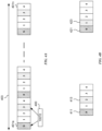
- FIG. 2 illustrates one exemplary transmission 200 of SSB(s), according to some aspects of the disclosure.
- SSBs can be transmitted during DRS windows 201a and 201b.
- each DRS window 201a-b can have a size 202 of 5 ms.
- these DRS windows can have other sizes.
- DRS windows 201a-b can repeat based on a DRS periodicity 203.
- DRS window 201a can include candidate SSB positions 205a-n.
- Base station 101 is able to transmit SSBs after base station 101 determines that the channel is free for transmission. Therefore, base station 101 can transmit SSBs on candidate SSB positions 207 after a successful LBT 209.
- the parameter Q is 4, and 4 physical beams are deployed.
- the aspects of this disclosure are not limited to this example.
- DRS window 201b can include candidate SSB positions 211a-n.
- Base station 101 is able to transmit SSBs after base station 101 determines that the channel is free for transmission. Therefore, base station 101 can transmit SSBs on candidate SSB positions 213 after a successful LBT 215.
- LBT success 215 occurs at a different candidate SSB position than LBT success 209. Therefore, the actual transmission of SSBs are time shifted across consecutive DRSs.
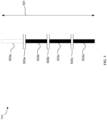
- FIG. 3 illustrates one exemplary SSB grouping, according to some aspects of this disclosure.
- the number of candidate SSB positions can be extended from 10 positions to 20 positions. By increasing the number of candidate SSB positions, the probability of LBT success increases. Additionally, or alternatively, the candidate SSB positions within a DRS window can be divided into different SSB groups at least based on the value of a parameter Q.
- parameter Q can be indicated and/or transmitted by base station 101 to UE 105 using Master Information Block (MIB), payload of PBCH, and/or System Information Block 1 (SIB1).
- MIB Master Information Block
- SIB1 System Information Block 1
- UE 105 can perform the grouping of the SSBs. Additionally, or alternatively, base station 101 can use other signaling to transmit the value of the parameter Q. In some examples, base station 101 can use other parameters to signal to UE 105 the SSB groups and/or SSB grouping scheme.
- the candidate SSB positions in time window and/or a half frame can be indexed in an ascending order in time from, for example, 0 to L-1.
- FIG. 3 illustrates candidate SSB positions in a time window (e.g., DRS window 300) that are grouped into four groups.
- the aspects of this disclosure are not limited to this example, and other number of grouping and other methods of grouping can be used.
- the candidate SSB positions in the time window and/or half frame are grouped as following:
- UE 101 when UE 101 receives data on the Physical Downlink Share Channel (PDSCH), UE 101 assumes the SSB group transmissions according to the ssb-PositionsInBurst IE as indicated in SIB1 and/or a dedicated signaling.
- ssb-PositionsInBurst IE in Rel-15 NR each bit in the ssb-PositionsInBurst IE corresponds to one candidate SSB position.
- each bit in the ssb-PositionsInBurst IE can correspond to one SSB group.
- UE 101 assumes that the PRBs containing SSB group transmission resources are not available for PDSCH in the OFDM symbols where SSB group is transmitted.
- UE assumes that other later Quasi Co-located (QCLed) SSB will not be transmitted in the same DRS window and hence, UE 101 does not perform rate-matching for PDSCH transmission as long as one of the QCLed SSBs in the same DRS window 300 has been detected by UE 101.
- UE 101 determines that candidate SSB position 0 (309) in SSB group 301 is used for SSB transmission and UE 101 receives the SSB position 0 (309).
- UE 101 can determine or assume that the corresponding QCLed candidate SSB positions (4, 8, 12, and 16) in the same SSB group 301 are not being used for SSB transmission. And therefore, UE 101 does not perform rate-matching operation for PDSCH transmission for the corresponding candidate SSB positions (4, 8, 12, and 16) in this DRS window 300.
- PUCCH Physical Uplink Control Channel
- UCI Uplink Control Information
- UE 101 can determine which format to use.
- a PUCCH Format 2 or 3 resource can have a configurable number of Physical Resource Blocks (PRBs) between, for example, 1 and, for example, 16.
- PRBs Physical Resource Blocks
- the upper end of this range of PRBs can be used for a case where a PUCCH resource carries large payloads.
- the large payload can include Channel State Information (CSI) feedback for multiple serving cells.
- the PUCCH Format 2 or 3 can support two interlaces to provide comparable UCI payload capacity as in Rel-15.
- interlacing can include techniques used to assign and/or allocate physical resources according to a pattern. In interlace resource allocation (RA), the basic unit of RA is an interlace.
- RA interlace resource allocation
- an interlace can include 10 equally spaced resource blocks (RBs) within a 20 MHz frequency bandwidth for 15 kHz Sub-Carrier Spacing (SCS).
- an interlace can include 5 equally spaced resource blocks (RBs) within a 20 MHz frequency bandwidth for 30 kHz SCS.
- the interlace resource allocation can include two interlaces having a first interlace index and a second interlace index.
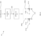
- FIGS. 4A and 4B illustrate exemplary methods for interlace signaling for PUCCH format, according to some aspects of this disclosure.
- FIG. 4A illustrates one exemplary bitmap 400 for interlace signaling for PUCCH format, according to some aspects of this disclosure.
- base station 101 transmits bitmap 400 to UE 101.
- base station 101 can use Downlink Control Information (DCI) to transmit the bitmap 400 to UE 100.
- DCI Downlink Control Information
- Base station 101 can transmit the DCI over PDCCH to UE 105.
- base station 101 can use other signals and/or signaling methods to communicate bitmap 400 to UE 105.
- base station 101 can use Radio Resource Control (RRC) message(s) to communicate/configure bitmap 400 to UE 101 and later use the DCI to inform UE 105 to use bitmap 400 for PUCCH transmission.
- RRC Radio Resource Control
- Bitmap 400 can include a one-to-one mapping with a set of interlaces of the serving cells.
- bitmap 400 can include bits mapping to corresponding interlace indices 401a-401n within Bandwidth Part (BWP) 403.
- BWP Bandwidth Part
- a value of '0' in bitmap 400 can indicate that the corresponding interlace is not allocated for this PUCCH resource.
- a value of ⁇ 1' in bitmap 400 can indicate that the corresponding interlace is allocated for the PUCCH resource.
- bitmap 400 of 10010 indicates that interlaces with index 0 and index 3 are allocated for the PUCCH resource. And, interlaces with index 1, index 2, and index 4 are not allocated for the PUCCH resource.
- the size of bitmap 400 can depend on the SCS of the PUCCH. In a non-limiting example, for a SCS of 30 kHz, the size of bitmap 400 can be 5 bits. In another non-limiting example, for a SCS of 15 kHz, the size of bitmap 400 can be 10 bits.
- N interlaces u is the number of interlace indices for SCS u.
- base station 101 can communicate the first interlace index k 1 to UE 105.
- Base station 101 can use DCI (or other signaling(s)) to communicate the first interlace index k 1 .
- UE 105 can use the first interlace index k 1 to determine the second interlace index k 2 using the first equation (equation (1)) above.
- base station 101 can communicate the first interlace index k 1 to UE 105.
- Base station 101 can use DCI (or other signaling(s)) to communicate the first interlace index k 1 .
- UE 105 can use the first interlace index k 1 to determine the second interlace index k 2 using the first equation (equation (2)) above.
- base station 101 can use DCI or other signaling(s) to communicate to UE 105 which equation to use. Additionally, or alternatively, the choice of the equation can be communicated to UE 105 when UE 105 first connects to base station 101. In some examples, UE 105 can independently determine which equation to use based on, for example, UE 105's measurement of channel(s) and UE 105 can communicate to base station 101 which equation was used.
- PUCCH Format 3 can support user multiplexing by assigning different OCCs or cyclic shifts of Zadoff-Chu sequence to different users.
- the user multiplexing for reference symbols can be based on the use of different cyclic shifts of the same base sequence for all multiplexed users.
- the user multiplexing for the UCI can be based on the application of pre-DFT (Discrete Fourier Transform) OCC for UCI symbols.
- TDM Time Division Multiplexing
- mapping between Cyclic Shift (CS) and OCC for PUCCH Format 3 is provided in Table 1.
- mapping as illustrated in Table 1 can be communicated from base station 101 to UE 105 using DCI or other signaling(s). Additionally, or alternatively, an OCC Index from Table 1 can be communicated from base station 101 to UE 105 using DCI or other signaling(s).
- UE 105 can use the OCC Index for generating the UCI symbol(s) and can use the CS Index for generating the DRMS symbol(s).
- OCC Index 0 for a PUCCH resource
- UE 105 can use the number of OCCs to determine the CS Index for the same PUCCH resource. For example, if the number of OCCs or the length of OCC sequence is 2, UE 105 uses CS Index 0 for generating the DRMS symbol(s). If the number of OCCs or the length of OCC sequence is 4, UE 105 also uses CS Index 0 to generate DRMS symbol(s).
- OCC Index is 1, if the number of OCCs or the length of OCC sequence is 2, UE 105 uses CS Index 6 for generating the DRMS symbol(s). If the number of OCCs or the length of OCC sequence is 4, UE 105 also uses CS Index 3 to generate DRMS symbol(s). As another non-limiting example, if OCC Index is 2, the number of OCCs cannot be 2. If the number of OCCs or the length of OCC sequence is 4, UE 105 also uses CS Index 6 to generate DRMS symbol(s). As another non-limiting example, if OCC Index is 4, the number of OCCs or the length of OCC sequence cannot be 2. If the number of OCCs or the length of OCC sequence is 4, UE 105 also uses CS Index 9 to generate DRMS symbol(s).
- the OCC index for a Physical Resource Block can be cycled across PRBs within an interlace.
- N SF PUCCH 2 is the number of OCCs.
- UE 105 can use the OCC Index for generating the UCI symbol(s).
- Frequency Division Multiplexing (FDM) is used for multiplexing UCI symbols and DMRS symbols for PUCCH Format 2.
- PUCCH Format 2 Frequency Division Multiplexing
- PAPR Peak-to-Average Power Ratio
- CM Cubic Metric
- the OCC indices and their cycling across PRBs within an interlace can be communicated from base station 101 to UE 105.
- base station 101 can use DCI (or other signaling(s)) to signal OCC indices and their cycling across PRBs.
- a scrambling sequence can be used in UE 105.
- UE 105 may apply the scrambling sequence per transmission to the symbols associated with PUCCH Format 2.
- the same OCC index can be applied to the PRBs within one interlace to generate a first sequence.
- the scrambling sequence can be applied to the first sequence to generate a second sequence. The second sequence can be used for generating UCI symbols.
- base station 101 can generate the scrambling sequence and communicate the scrambling sequence to UE 105.
- base station 101 can use DCI (or other signaling(s)) to communicate the scrambling sequence to UE 105.
- base station 101 can use DCI (or other signaling(s)) to communicate to UE 105 parameter(s) used for generating the scrambling sequence.
- the scrambling sequence generator (at UE 105 and/or base station 101) may be initialized with C-RNTI (Cell Radio Network Temporary Identifier), slot index, and/or cell ID (Identifier). In some examples, using slot index and/or cell ID can reduce interference(s) within and/or between cells.
- C-RNTI Cell Radio Network Temporary Identifier
- slot index and/or cell ID can reduce interference(s) within and/or between cells.
- PUSCH Physical Upload Shared Channel
- the minimum resource allocation granularity can be one interlace (e.g., 10 PRBs). This granularity can be too coarse for small PUSCH payloads.
- Some aspects of this disclosure provide methods and systems to support partial interlace allocation for PUSCH (e.g., in NR-U systems) and support signaling the partial interlace allocation.
- Downlink Control Information (DCI) transmitted from base station 101 can signal to UE 105 the resource allocation for partial interlace PUSCH.
- DCI Downlink Control Information
- one field in the DCI can be used to indicate the starting LBT bandwidth ( SB start ) and a length in terms of contagiously allocated LBT bandwidths (e.g., number of contagiously allocated LBT bandwidths - L SBs ).
- the DCI can include a Resource Indication Value (RIV) to indicate the starting LBT bandwidth and the number of contagiously allocated LBT bandwidths.
- RIV Resource Indication Value
- N BWP SB size is the number of LBT sub-bands within a Bandwidth Part (BWP).
- UE 105 After receiving the DCI, UE 105 can use the RIV and/or the starting LBT bandwidth and the number of contagiously allocated LBT bandwidths to determine the resource allocation for its partial interlace PUSCH. UE 105 can transmit data to base station 101 using the resource allocated in the partial interlace PUSCH.
- UE 105 can be configured by higher layers a set of PUSCH resource allocation patterns. Additionally, or alternatively, UE 105 can receive the set of PUSCH resource allocation patterns from base station 101. For example, UE 105 can receive the set of PUSCH resource allocation patterns from base station 101 using DCI transmitted by base station 101. In another examples, UE 105 can receive the set of PUSCH resource allocation patterns from base station 101 using RRC message(s).
- each pattern can indicate PUSCH interlace allocation across consecutive LBT bandwidths using a bitmap approach.
- a bitmap can be used to indicate one or more LBT sub-bands that are allocated for PUSCH transmission.
- the bitmap can indicate one or more sub-bands that are not used/available for PUSCH transmission (e.g., indicate rate-matching around the indicated LBT sub-bands for PUSCH transmission.)
- FIG. 5 illustrates one exemplary partial interlace PUSCH resource allocation 500, according to some aspects of the disclosure.
- BWP 501 can include four LBT sub-band 503a-503d. Each LBT sub-band 503 can be separated from the consecutive LBT sub-band 503 by a guard band 505 (505a-505c). It is noted the aspects of this disclosure are not limited to this example and other number of LBT sub-bands and guard bands can be used.
- LBT sub-band 503a is not used for PUSCH transmission, but LBT sub-bands 53b-d are allocated for PUSCH transmission.
- This resource allocation for partial interlace PUSCH can be set using Pattern Index 0 from Table 2 below.
- Pattern Index 0 can correspond to bitmap 0111 (Alternative 1). In this example, bit value '0' in the bitmap indicates that the corresponding LBT sub-band (e.g., LBT sub-band 503a) is not used/available for PUSCH transmission. Bit value '1' in the bitmap indicates that the corresponding LBT sub-bands (e.g., LBT sub-bands 503b-d) are allocated for PUSCH transmission. In another example, Pattern Index 0 can correspond to bitmap 1000 (Alternative 2). In this example, bit value '1' in the bitmap indicates that the corresponding LBT sub-band (e.g., LBT sub-band 503a) is not used/available for PUSCH transmission. Bit value '0' in the bitmap indicates that the corresponding LBT sub-bands (e.g., LBT sub-bands 503b-d) are allocated for PUSCH transmission.
- base station 101 may transmit the Pattern Index and/or Alternative 1 or 2 bitmaps to UE 105 using DCI (or other signaling(s)).
- Base station 101 can use measurements such as, but not limited to, the downlink channel's measurements to determine which one of the Alternative 1 or 2 bitmaps to send to UE 105. For example, if base station 101 determines (e.g., using Channel State Information (CSI) report from UEs such as UE 105) that the downlink channel is congested, base station 101 can send Alternative 2 bitmap (e.g., 1000) to UE 105.
- CSI Channel State Information
- Table 2 - Partial Interlace PUSCH Resource Allocation Pattern Index Alternative 1 Alternative 2 0 0111 1000 1 1100 0011 2 0110 1001 ... ... ...
- configuration for cell specific PUCCH is broadcasted.
- base station 101 can transmit configuration for cell specific PUCCH.
- Base station 101 can use MIB, SIB 1, and/or DCI to transmit the configuration for cell specific PUCCH.
- the configuration can be provided by the parameter pucch-ResourceCommon in the PUCCH-ConfigCommon IE, which is signaled via SIB1 for PUCCH transmission(s) in an initial uplink (UL) BWP of an Special Cell (SpCell).
- SpCell can include a Primary Cell (PCell) or a Primary Secondary Cell (PSCell), according to some examples.
- the parameter can take an integer value in the range of 0 - 15, which can select one PUCCH resource set predefined in, for example, 3GPP specification, according to some aspects. Additionally, UE 105 can determine a PUCCH resource configuration (such as, but not limited to, PRB location, initial cyclic shift index, etc.) depending on the PUCCH resource indicator in DCI using a predefined equation.
- a PUCCH resource configuration such as, but not limited to, PRB location, initial cyclic shift index, etc.
- Some aspects of this disclosure are directed to methods and systems for signaling the interlaced cell-specific PUCCH resource allocation prior to a dedicated RRC connection. For examples, some methods and systems of this disclosure can increase the UE multiplexing capacity to minimize the cell-specific PUCCH overhead.
- UE 105 before connecting to base station 101, can search for a cell to attach. After completing the search, UE 105 can perform a Radio Resource Control (RRC) connection setup process.
- RRC Radio Resource Control
- UE 105 can send an attach request to base station 101 and/or a mobility management entity (MME) (not shown) associated with base station 101.
- MME mobility management entity
- the attach request can include an identifier of UE 105.
- MME can send a setup request to, for example, base station 101.
- base station 101 after receiving the setup request, and if base station 101 does not know the capabilities of UE 105, base station 101 can send a request to UE 105 to request the capabilities of UE 105.
- UE 105 can send its capabilities to base station 101.
- base station 101 can send an RRC connection reconfiguration message back to UE 105.
- UE 105 can start data communication using base station 101.
- UE 105 can send CSI report(s) to the base station.
- SIB1 can include parameters that define the PUCCH (e.g., PUCCH Resource).
- One parameter defining the PUCCH can include "PRB offset" value.
- SIB1 can be used for signaling the interlaced cell-specific PUCCH resource allocation.
- the "PRB offset" value configured by SIB 1 may be re-interpreted by UE 105 as starting interlace index.
- S int is the starting interlace
- r PUCCH is the number of cell-specific PUCCH resources
- N cs is the number of initial cyclic shift (CS) index sets.
- base station 101 using the "PRB offset" value configured in SIB 1 can allocate resources for the interlaced cell-specific PUCCH transmission at UE 105.
- the PUCCH resource with interlace PUCCH Format 0 or 1 may include a time-domain Orthogonal Cover Code (OCC) ⁇ ⁇ 0 , ⁇ 1 ⁇ with length N SF PUCCH , 0 / 1 .
- OCC Orthogonal Cover Code
- N SF PUCCH , 0 / 1 2 , which can increase the capacity of interlaced PUCCH Format 0 or 1 two times.
- FIG. 6 illustrates one simplified exemplary system 600 for enhanced PUCCH Format 0 or 1 with time-domain OCC, according to some aspects of this disclosure.
- generating the PUCCH Format 0 or 1 can include one or more of generating PUCCH baseband sequence, group and sequence hopping, cyclic shift, scrambling, and/or modulation.
- the simplified exemplary system 600 illustrates a first sequence 601 that is generated from a PUCCH baseband sequence and cyclic shifted based on 1 bit Hybrid Automatic Repeat Request (Hybrid ARQ or HARQ) ACK (acknowledgment).
- first sequence 601 is input to scrambling 603 to generate a second sequence 605.
- the scramble second sequence 605 can be modulated using, for example, Quadrature Phase Shift Keying (QPSK) code modulator 607.
- Output of modulator 607 includes two symbols 609a and 609b.
- QPSK Quadrature Phase Shift Keying
- system 600 further include time-domain OCC ⁇ ⁇ 0 , ⁇ 1 ⁇ 613a and 613b that are modulated (e.g., multiplied) 611a and 611b to the two symbols 609a and 609b to generate the PUCCH Format 0 or 1 615.
- resource allocation is used to allocate resource blocks for a transmission.
- Resource allocation type specifies how the resource blocks are to be allocated.
- two resource allocation types can be defined.
- Type-0 can be a RA with non-contiguous allocation using a bitmap where each bit represents a Resource Block Group (RBG).
- Type-1 can be a RA with contiguous allocation using Resource Indication Value (RIV), which indicates a start Resource Block (RB) and a bandwidth (in RBs) within a BWP.
- RBG Resource Block Group
- RIV Resource Indication Value
- Some aspects of this disclosure are directed to methods and systems to support dynamically switching between interlace RA and legacy RA.
- methods and systems are provided to support dynamically switching between interlace RA and legacy Rel-15 RA using DCI.
- UE 105 and/or base station 101 can support and operate using both interlace RA (e.g., Rel-16 interlace RA) and legacy RA (e.g., Rel-15 RA).
- base station 101 can be configured to send control information/instructions to UE 105 to dynamically switch between the interlace RA and legacy RA.
- the switching between interlace PUSCH RA and Type-1 RA can be supported using DCI.
- base station 101 can use DCI to instruct UE 105 to dynamically switch between the RAs.
- the DCI can be based on inside of Channel Occupancy Time (COT) or outside of COT.
- COT Channel Occupancy Time
- higher signaling such as, but not limited to, an RRC message
- RRC message can be used to signal to base station 101 and/or to UE 105 that UE 105 and/or base station 101 is capable of switching between interlace PUSCH RA and Type-1 RA.
- UE 105 can inform base station 101 that UE 105 supports both interlace RA and legacy RA. So, base station 101 can use DCI to instruct UE 105 to dynamically switch between these RAs.
- FDRA Most Significant Bit
- FDRA can be a field in DCI.
- the number of bits for the FDRA field can be determined using the following: max log 2 N RB DL , BWP N RB DL , BWP + 1 / 2 , X u + 1 bits
- X u is the bits number of Rel-16 interlace PUSCH.
- N RB DL , BWP is the number of RBs in a downlink BWP.
- the switching between interlace PUSCH RA and Type-0 and/or Type-1 RA as the PUSCH RA can also be supported by DCI.
- base station 101 and UE 105 can communicate using, for example, RRC message(s) which two RA schemes among three are supported and/or activated by UE 105.
- UE 105 can inform base station 101 (e.g., using RRC message(s)) that UE 105 supports and/or has activated Type-0 RA and interlace PUSCH RA.
- UE 105 can inform base station 101 (e.g., using RRC message(s)) that UE 105 supports and/or has activated Type-1 RA and interlace PUSCH RA.
- base station 101 can use DCI to dynamically select of the RAs for PUSCH RA.
- base station 101 can use the MSB of FDRA field of DCI to dynamically select one of the activated RA schemes for PUSCH RA.
- base station 101 can also select different interlace RA schemes to be used by UE 105.
- the interlace RA schemes can include contiguous interlace RA and non-contiguous interlace RA.
- FIG. 4B illustrates a non-contiguous interlace RA where interlace indices 411 and 413 are non-contiguous and also illustrates a contiguous interlace RA where interlace indices 421 and 423 are contiguous.
- different RIV values can be associated with different interlace RA schemes.
- a 6-bit RIV field is included in the DCI for 15 kHz.
- the RIV value from 0 to 54 is used to indicate contiguous interlaces RA, e.g., a starting interlace and a length (e.g., number of contiguous interlace indices). While, the other RIV value, e.g., 55-63 can be used to indicate non-contiguous interlaces RA (e.g., to one-to-one indicate a predefined or RRC-configured interlaces combinations). With this approach, a single DCI can dynamically switch between contiguous and non-contiguous interlace RA for PUSCH transmissions.
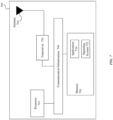
- FIG. 7 illustrates a block diagram of an example system 700 of an electronic device implementing mechanisms for downlink transmission and interlace uplink transmission, according to some aspects of the disclosure.
- System 700 may be any of the electronic devices (e.g., base station 101, UE 105) of system 100.
- System 700 includes processor 710, one or more transceivers 720, communication infrastructure 740, memory 750, operating system 752, application 754, and one or more antenna 760.
- Illustrated systems are provided as exemplary parts of system 700, and system 700 can include other circuit(s) and subsystem(s).
- the systems of system 700 are illustrated as separate components, the aspects of this disclosure can include any combination of these, less, or more components.
- Memory 750 may include random access memory (RAM) and/or cache, and may include control logic (e.g., computer software) and/or data. Memory 750 may include other storage devices or memory such as, but not limited to, a hard disk drive and/or a removable storage device/unit. According to some examples, operating system 752 can be stored in memory 750. Operating system 752 can manage transfer of data from memory 750 and/or one or more applications 754 to processor 710 and/or one or more transceivers 720. In some examples, operating system 752 maintains one or more network protocol stacks (e.g., Internet protocol stack, cellular protocol stack, and the like) that can include a number of logical layers. At corresponding layers of the protocol stack, operating system 752 includes control mechanism and data structures to perform the functions associated with that layer.
- network protocol stacks e.g., Internet protocol stack, cellular protocol stack, and the like
- application 754 can be stored in memory 750.
- Application 754 can include applications (e.g., user applications) used by wireless system 700 and/or a user of wireless system 700.
- the applications in application 754 can include applications such as, but not limited to, Siri TM , FaceTime TM , radio streaming, video streaming, remote control, and/or other user applications.
- System 700 can also include communication infrastructure 740.
- Communication infrastructure 740 provides communication between, for example, processor 710, one or more transceivers 720, and memory 750.
- communication infrastructure 740 may be a bus.
- Processor 710 together with instructions stored in memory 750 performs operations enabling system 700 of system 100 to implement mechanisms for downlink transmission and interlace uplink transmission, as described herein.
- one or more transmitters 720 may be coupled to antenna 760.
- Antenna 760 may include one or more antennas that may be the same or different types.
- One or more transceivers 720 allow system 700 to communicate with other devices that may be wired and/or wireless.
- one or more transceivers 720 can include processors, controllers, radios, sockets, plugs, buffers, and like circuits/devices used for connecting to and communication on networks.
- one or more transceivers 720 include one or more circuits to connect to and communicate on wired and/or wireless networks.
- one or more transceivers 720 can include a cellular subsystem, a WLAN subsystem, and/or a Bluetooth TM subsystem, each including its own radio transceiver and protocol(s) as will be understood by those skilled arts based on the discussion provided herein. In some implementations, one or more transceivers 720 can include more or fewer systems for communicating with other devices.
- one or more transceivers 720 can include one or more circuits (including a WLAN transceiver) to enable connection(s) and communication over WLAN networks such as, but not limited to, networks based on standards described in IEEE 802.11.
- one or more transceivers 720 can include one or more circuits (including a Bluetooth TM transceiver) to enable connection(s) and communication based on, for example, Bluetooth TM protocol, the Bluetooth TM Low Energy protocol, or the Bluetooth TM Low Energy Long Range protocol.
- transceiver 720 can include a Bluetooth TM transceiver.
- one or more transceivers 720 can include one or more circuits (including a cellular transceiver) for connecting to and communicating on cellular networks.
- the cellular networks can include, but are not limited to, 3G/4G/5G networks such as Universal Mobile Telecommunications System (UMTS), Long-Term Evolution (LTE), and the like.
- UMTS Universal Mobile Telecommunications System
- LTE Long-Term Evolution
- one or more transceivers 220 can be configured to operate according to one or more of Rel-15, Rel-16, Rel-17, NR, NR-U or later of 3GPP standard.
- processor 710 alone or in combination with computer instructions stored within memory 750, and/or one or more transceiver 720, implements the methods and mechanisms discussed in this disclosure.
- processor 710 alone or in combination with computer instructions stored within memory 750, and/or one or more transceiver 720, implements mechanisms for indicating the actual SSBs transmission for PDSCH rate-matching purposes.
- processor 710 alone or in combination with computer instructions stored within memory 750, and/or one or more transceiver 720, implements mechanisms for PDSCH resource mapping for operation with shared spectrum channel access.
- processor 710 alone or in combination with computer instructions stored within memory 750, and/or one or more transceiver 720, implements mechanisms for resource allocation for interlaced PUCCH Format 2 or 3 and for signaling the second interlace index. Additionally, or alternatively, processor 710, alone or in combination with computer instructions stored within memory 750, and/or one or more transceiver 720, implements mechanisms for mapping between OCC index applied on the UCI symbols and the cyclic shift applied to DMRS symbols.
- processor 710 alone or in combination with computer instructions stored within memory 750, and/or one or more transceiver 720, implements mechanisms for resource allocation for partial interlace Physical Upload Shared Channel (PUSCH).
- processor 710 alone or in combination with computer instructions stored within memory 750, and/or one or more transceiver 720, implements mechanisms for signaling the interlaces cell-specific PUCCH resource allocation prior to a dedicated RRC connection and/or increasing the UE multiplexing capacity to minimize the cell-specific PUCCH overhead.
- PUSCH Physical Upload Shared Channel
- processor 710 alone or in combination with computer instructions stored within memory 750, and/or one or more transceiver 720, implements mechanisms for supporting dynamically switching between interlace and legacy Rel-15 RA using DCI format.
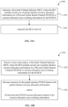
- FIG. 8A illustrates an example method 800 for a system (for example, base station) supporting mechanisms for implementing PDSCH resource mapping, according to some aspects of the disclosure.
- FIG. 8A may be described with regard to elements of FIGs. 1 , 2 , 3 , 7 , and 11 .
- Method 800 may represent the operation of an electronic device (for example, base station 101 of FIG. 1 ) implementing mechanisms for implementing PDSCH resource mapping.
- Method 800 may also be performed by system 700 of FIG. 7 and/or computer system 1100 of FIG. 11 .
- method 800 is not limited to the specific aspects depicted in those figures and other systems may be used to perform the method as will be understood by those skilled in the art. It is to be appreciated that not all operations may be needed, and the operations may not be performed in the same order as shown in FIG. 8A .
- candidate Synchronization Signal Block (SSB) positions in a time window are divided into a plurality of groups.
- base station 101 is configured to group the candidate SSB positions into a plurality of groups.
- the candidate SSB positions are divided in four groups.
- the time window can be a DRS window (e.g., DRS window 300).
- step 802 is performed on a per DRS window.
- information associated with the plurality of groups of candidate SSB positions are communicated to the UE (e.g., UE 105).
- the grouping of the candidate SSB positions is based on the parameter Q as discussed above.
- base station 101 can transmit the parameter Q to UE 105 using MIB, payload of PBCH, or SIB1. Additionally, base station 101 can communicate the number of candidate SSB positions (e.g., parameter L discussed above) to UE 105.
- an LBT procedure is performed. For example base station 101 performs the LBT procedure. If the LBT procedure is successful, base station 101 can determine a first group of candidate SSB positions and can transmit one or more SSBs on one or more candidate SSB positions of the first group at 808.
- FIG. 8B illustrates an example method 820 for a system (for example, a UE) supporting mechanisms for implementing PDSCH resource mapping, according to some aspects of the disclosure.
- a system for example, a UE
- FIG. 8B may be described with regard to elements of FIGs. 1 , 2 , 3 , 7 , and 11 .
- Method 820 may represent the operation of an electronic device (for example, UE 105 of FIG. 1 ) implementing mechanisms for implementing PDSCH resource mapping.
- Method 820 may also be performed by system 700 of FIG. 7 and/or computer system 1100 of FIG. 11 . But method 820 is not limited to the specific aspects depicted in those figures and other systems may be used to perform the method as will be understood by those skilled in the art. It is to be appreciated that not all operations may be needed, and the operations may not be performed in the same order as shown in FIG. 8B .
- information associated with a plurality of groups of candidate SSB positions are received from a base station (e.g., base station 105).
- the grouping of the candidate SSB positions is based on the parameter Q as discussed above.
- UE 105 can receive the parameter Q to from base station 101 using MIB, payload of PBCH, or SIB1. Additionally, UE 105 can receive the maximum number of candidate SSB positions (e.g., parameter L discussed above) from base station 101.
- UE 105 can receive an SSB at a first group of candidate SSB positions.
- UE 105 can determine that the first group of candidate SSB positions is used for receiving SSBs. According to some aspects, if UE 105 receives PDSCH with PDSCH resource allocation overlapping with PRBs containing SSB group transmission resources, UE 101 assumes that the PRBs containing SSB group transmission resources are not available for PDSCH in the OFDM symbols where SSB group is transmitted.
- FIG. 9A illustrates an example method for a system (for example, base station) supporting mechanisms for implementing resource allocation for interlaces PUCCH, according to some aspects of the disclosure.
- a system for example, base station
- FIG. 9A may be described with regard to elements of FIGs. 1 , 4A , 4B , 6 , 7 , and 11 .
- Method 900 may represent the operation of an electronic device (for example, base station 101 of FIG. 1 ) implementing mechanisms for implementing resource allocation for interlaces PUCCH.
- Method 900 may also be performed by system 700 of FIG. 7 and/or computer system 1100 of FIG. 11 .
- method 900 is not limited to the specific aspects depicted in those figures and other systems may be used to perform the method as will be understood by those skilled in the art. It is to be appreciated that not all operations may be needed, and the operations may not be performed in the same order as shown in FIG. 9A .
- a Downlink Channel Indicator is generated.
- base station 101 generates the DCI.
- the DCI includes interlace resource allocation information for a Physical Uplink Control Channel (PUCCH).
- PUCCH Physical Uplink Control Channel
- base station 101 transmits the DCI to the UE.
- the interlace resource allocation information for the PUCCH includes a bitmap, wherein a first value of a bit of the bitmap indicates that a corresponding interlace is allocated for the PUCCH.
- the size of the bitmap can be based on a sub-carrier spacing of the PUCCH.
- the interlace resource allocation information includes a first interlace index and a second interlace index is calculated by UE 105 using the first interlace index, for example, as discussed above with respect to equations (1) or (2).
- the second interlace index is based on the first interlace index and a number of interlaces for a sub-carrier spacing of the PUCCH.
- the PUCCH can include at least one of PUCCH Format 2 or PUCCH Format 3.
- the DCI communicated from base station 101 to UE 105 can also include a mapping between Orthogonal Cover Code (OCC) index applied on the UCI symbols and the cyclic shift applied to DMRS symbols.
- OCC Orthogonal Cover Code
- the mapping between Cyclic Shift (CS) and OCC for PUCCH Forma 3 is provided in Table 1 discussed above.
- the mapping as illustrated in Table 1 can be communicated from base station 101 to UE 105 using the DCI (or other signaling(s)).
- an OCC Index from Table 1 can be communicated from base station 101 to UE 105 using DCI (or other signaling(s)).
- the DCI can further include information for UE 105 to use a plurality of OCC indices and to cycle them across PRBs within an interlace. Additionally, or alternatively, the DCI can include information of UE 105 to apply a scrambling sequence per transmission to the symbols associated with PUCCH.
- base station 101 can be further configured to generate System Information Block 1 (SIB1), where the SIB1 can include a value configured to signal interlaced cell-specific PUCCH resource allocation to UE 105.
- SIB1 System Information Block 1
- FIG. 9B illustrates an example method for a system (for example, a user equipment (UE)) supporting mechanisms for implementing resource allocation for interlaces PUCCH, according to some aspects of the disclosure.
- a system for example, a user equipment (UE)
- FIG. 9B may be described with regard to elements of FIGs. 1 , 4A , 4B , 6 , 7 , and 11 .
- Method 920 may represent the operation of an electronic device (for example, UE 105 of FIG. 1 ) implementing mechanisms for implementing resource allocation for interlaces PUCCH. Method 920 may also be performed by system 700 of FIG. 7 and/or computer system 1100 of FIG. 11 .
- method 920 is not limited to the specific aspects depicted in those figures and other systems may be used to perform the method as will be understood by those skilled in the art. It is to be appreciated that not all operations may be needed, and the operations may not be performed in the same order as shown in FIG. 9B .
- a Downlink Channel Indicator is received.
- UE 105 receives the DCI from base station 101.
- the DCI includes interlace resource allocation information for a Physical Uplink Control Channel (PUCCH).
- PUCCH Physical Uplink Control Channel
- UE 105 can allocate resources on the PUCCH based on the interlace resource allocation information. After allocating the resource, UE 105 can use the allocated resource for PUCCH transmission to, for example, base station 101.
- the interlace resource allocation information for the PUCCH can include a bitmap, where a first value of a bit of the bitmap indicates that a corresponding interlace is allocated for the PUCCH.
- the interlace resource allocation information can include a first interlace index.
- UE 105 can be further configured to calculate a second interlace index using the first interlace index. For example, UE 105 can calculate the second interlace index based on the first interlace index and a number of interlaces for a sub-carrier spacing of the PUCCH.
- the DCI can also include a mapping between Orthogonal Cover Code (OCC) index applied on an Uplink Control Information (UCI) symbol and a cyclic shift (CS) applied to a DeModulation Reference Signal (DMRS) symbol (for example, as discussed with respect to Table 1 above).
- OCC Orthogonal Cover Code
- CS cyclic shift
- DMRS DeModulation Reference Signal
- method 920 can further includes using the OCC Index to determine a CS index, generating the UCI symbol using the OCC index, and generating the DRMS symbol using the CS Index.
- method 920 can further include determining a plurality of Orthogonal Cover Code (OCC) indices based on the received DCI and cycling the plurality of OCC indices across Physical Resource Blocks (PRBs) within an interlace.
- OCC Orthogonal Cover Code
- method 920 can further include applying, based on the received DCI, a scrambling sequence per transmission to one or more symbols associated with the PUCCH.
- method 920 can further include receiving System Information Block 1 (SIB1).
- SIB1 can include a value configured to signal interlaced cell-specific PUCCH resource allocation to UE 105.
- FIG. 10A illustrates an example method for a system (for example, a base station) supporting mechanisms for implementing resource allocation for partial interlaces PUSCH and/or resource allocation type switching, according to some aspects of the disclosure.
- a system for example, a base station
- FIG. 10A may be described with regard to elements of FIGs. 1 , 5 , 7 , and 11 .
- Method 1000 may represent the operation of an electronic device (for example, base station 101 of FIG. 1 ) implementing mechanisms for implementing resource allocation for partial interlaces PUSCH and/or resource allocation type switching. Method 1000 may also be performed by system 700 of FIG. 7 and/or computer system 1100 of FIG. 11 .
- method 1000 is not limited to the specific aspects depicted in those figures and other systems may be used to perform the method as will be understood by those skilled in the art. It is to be appreciated that not all operations may be needed, and the operations may not be performed in the same order as shown in FIG. 10A .
- a Downlink Channel Indicator is generated.
- base station 101 generates the DCI.
- the DCI can include at least one of partial interlace resource allocation information for a Physical Uplink Shared Channel (PUSCH) or resource allocation type switching information for the PUSCH.
- PUSCH Physical Uplink Shared Channel
- base station 101 transmits the DCI to the UE.
- the DCI includes a field to indicate a starting listen-to-talk (LBT) bandwidth and a number of contagiously allocated LBT bandwidths. Additionally, or alternatively, the field in the DCI can include a resource indication value (RIV) determined based on the starting LBT bandwidth, the number of contagiously allocated LBT bandwidths, and a number of LBT sub-bands within a bandwidth part (BWP).
- LBT listen-to-talk
- BWP bandwidth part
- the DCI includes an allocation pattern.
- an allocation pattern is discussed above with respect to Table 2.
- the allocation pattern includes a bitmap, where a bit in the bitmap is set to a first value to indicate an LBT bandwidth not available for PUSCH transmission.
- a Most Significant Bit (MSB) of a frequency domain resource allocation (FDRA) field of the DCI includes the resource allocation type switching information, discussed, for example, with respect to equation (7).
- the MSB of the FDRA field of the DCI can be used to dynamically select one of two or more activated resource allocation schemes for PUSCH resource allocation at the UE.
- the DCI further includes a Resource Indication Value (RIV).
- RIV Resource Indication Value
- a first set of values for the RIV indicate contiguous interlaces resource allocation (RA), and wherein a second set of values for the RIV indicate non-contiguous interlaces RA.
- FIG. 10B illustrates an example method for a system (for example, a user equipment (UE)) supporting mechanisms for implementing resource allocation for partial interlaces PUSCH and/or resource allocation type switching, according to some aspects of the disclosure.
- a system for example, a user equipment (UE)
- UE user equipment
- FIG. 10B may be described with regard to elements of FIGs. 1 , 5 , 7 , and 11 .
- Method 1020 may represent the operation of an electronic device (for example, UE 105 of FIG. 1 ) implementing mechanisms for implementing resource allocation for partial interlaces PUSCH and/or resource allocation type switching.
- Method 1020 may also be performed by system 700 of FIG. 7 and/or computer system 1100 of FIG. 11 .
- method 1020 is not limited to the specific aspects depicted in those figures and other systems may be used to perform the method as will be understood by those skilled in the art. It is to be appreciated that not all operations may be needed, and the operations may not be performed in the same order as shown in FIG. 10B .
- a Downlink Channel Indicator is received.
- UE 105 receives the DCI from base station 101.
- the DCI can include at least one of partial interlace resource allocation information for a Physical Uplink Shared Channel (PUSCH) or resource allocation type switching information for the PUSCH.
- PUSCH Physical Uplink Shared Channel
- UE 105 can allocate resources for the partial interlace PUSCH based on the partial interlace resource allocation information. After allocating the resources, UE 105 can use the allocated resources for PUSCH transmission to, for example, base station 101. Additionally, or alternatively, UE 105 can dynamically switch between PUSCH resource allocations based on the resource allocation type switching information.
- step 1024 can include using a field in the DCI to determine a starting listen-to-talk (LBT) bandwidth and a number of contagiously allocated LBT bandwidths. Additionally, or alternatively, step 1024 can include using the field in the DCI to determine a resource indication value (RIV). The RIV is determined based on the starting LBT bandwidth, the number of contagiously allocated LBT bandwidths, and a number of LBT sub-bands within a bandwidth part (BWP).
- LBT listen-to-talk
- BWP bandwidth part
- the DCI includes an allocation pattern.
- an allocation pattern is discussed above with respect to Table 2.
- the allocation pattern includes a bitmap, where a bit in the bitmap is set to a first value to indicate an LBT bandwidth not available for PUSCH transmission.
- Step 1024 can further include detecting the allocation pattern in the DCI and using the allocation patter to allocate the resources for the partial interlace PUSCH.
- step 1024 can include inspecting and/or detecting a Most Significant Bit (MSB) of a frequency domain resource allocation (FDRA) field of the DCI to determine the resource allocation type switching information, discussed, for example, with respect to equation (7).
- MSB Most Significant Bit
- FDRA frequency domain resource allocation
- UE 105 can use the MSB of the FDRA field of the DCI to dynamically select one of two or more activated resource allocation schemes for PUSCH resource allocation.
- method 1020 can further include using the received DCI to determine whether to use contiguous interlaces resource allocation to non-contiguous interlaces resource allocation.
- the received DCI further includes a Resource Indication Value (RIV).
- RIV Resource Indication Value
- a first set of values for the RIV indicate contiguous interlaces resource allocation (RA), and wherein a second set of values for the RIV indicate non-contiguous interlaces RA.
- method 1020 can include determining RIV from the received DCI and comparing the value of the RIV to a first set of values. If the value of the RIV is in the first set of values, UE 105 uses contiguous interlaces resource allocation (RA).
- UE uses non-contiguous interlaces resource allocation (RA).
- method 1020 can include comparing the value of the RIB with a second set of value. If the value of the RIV is in the second set of values, UE uses non-contiguous interlaces resource allocation (RA).
- base station 101 can communicate the first and/or second set of values to UE 105 using RRC message(s), DCI, or other signaling(s).
- Computer system 1100 can be any well-known computer capable of performing the functions described herein such as devices 101, 105 of FIG. 1 , or 700 of FIG. 7 .
- Computer system 1100 includes one or more processors (also called central processing units, or CPUs), such as a processor 1104.
- Processor 1104 is connected to a communication infrastructure 1106 (e.g., a bus.)
- Computer system 1100 also includes user input/output device(s) 1103, such as monitors, keyboards, pointing devices, etc., that communicate with communication infrastructure 1106 through user input/output interface(s) 1102.
- Computer system 1100 also includes a main or primary memory 1108, such as random access memory (RAM).
- Main memory 1108 may include one or more levels of cache.
- Main memory 1108 has stored therein control logic (e.g., computer software) and/or data.
- Computer system 1100 may also include one or more secondary storage devices or memory 1110.
- Secondary memory 1110 may include, for example, a hard disk drive 1112 and/or a removable storage device or drive 1114.
- Removable storage drive 1114 may be a floppy disk drive, a magnetic tape drive, a compact disk drive, an optical storage device, tape backup device, and/or any other storage device/drive.
- Removable storage drive 1114 may interact with a removable storage unit 1118.
- Removable storage unit 1118 includes a computer usable or readable storage device having stored thereon computer software (control logic) and/or data.
- Removable storage unit 1118 may be a floppy disk, magnetic tape, compact disk, DVD, optical storage disk, and/ any other computer data storage device.
- Removable storage drive 1114 reads from and/or writes to removable storage unit 1118 in a well-known manner.
- secondary memory 1110 may include other means, instrumentalities or other approaches for allowing computer programs and/or other instructions and/or data to be accessed by computer system 1100.
- Such means, instrumentalities or other approaches may include, for example, a removable storage unit 1122 and an interface 1120.
- the removable storage unit 1122 and the interface 1120 may include a program cartridge and cartridge interface (such as that found in video game devices), a removable memory chip (such as an EPROM or PROM) and associated socket, a memory stick and USB port, a memory card and associated memory card slot, and/or any other removable storage unit and associated interface.
- Computer system 1100 may further include a communication or network interface 1124.
- Communication interface 1124 enables computer system 1100 to communicate and interact with any combination of remote devices, remote networks, remote entities, etc. (individually and collectively referenced by reference number 1128).
- communication interface 1124 may allow computer system 1100 to communicate with remote devices 1128 over communications path 1126, which may be wired and/or wireless, and which may include any combination of LANs, WANs, the Internet, etc. Control logic and/or data may be transmitted to and from computer system 1100 via communication path 1126.
- a tangible, non-transitory apparatus or article of manufacture includes a tangible, non-transitory computer useable or readable medium having control logic (software) stored thereon is also referred to herein as a computer program product or program storage device.
- control logic software stored thereon
- control logic when executed by one or more data processing devices (such as computer system 1100), causes such data processing devices to operate as described herein.
- references herein to "one aspect,” “aspects” “an example,” “examples,” or similar phrases, indicate that the aspect(s) described may include a particular feature, structure, or characteristic, but every aspect may not necessarily include the particular feature, structure, or characteristic. Moreover, such phrases are not necessarily referring to the same aspect. Further, when a particular feature, structure, or characteristic is described in connection with an aspect, it would be within the knowledge of persons skilled in the relevant art(s) to incorporate such feature, structure, or characteristic into other aspects whether or not explicitly mentioned or described herein.
- personally identifiable information should follow privacy policies and practices that are generally recognized as meeting or exceeding industry or governmental requirements for maintaining the privacy of users.
- personally identifiable information data should be managed and handled so as to minimize risks of unintentional or unauthorized access or use, and the nature of authorized use should be clearly indicated to users.
Landscapes
- Engineering & Computer Science (AREA)
- Computer Networks & Wireless Communication (AREA)
- Signal Processing (AREA)
- Mobile Radio Communication Systems (AREA)
Priority Applications (1)
| Application Number | Priority Date | Filing Date | Title |
|---|---|---|---|
| EP24201225.0A EP4460133A3 (de) | 2020-05-14 | 2020-05-14 | Verfahren und systeme zur downlink-übertragung und zwischenzeilen-uplink-übertragung |
Applications Claiming Priority (3)
| Application Number | Priority Date | Filing Date | Title |
|---|---|---|---|
| PCT/CN2020/090130 WO2021226901A1 (en) | 2020-05-14 | 2020-05-14 | Methods and systems for downlink transmission and interlace uplink transmission |
| EP24201225.0A EP4460133A3 (de) | 2020-05-14 | 2020-05-14 | Verfahren und systeme zur downlink-übertragung und zwischenzeilen-uplink-übertragung |
| EP20934964.6A EP4136896A4 (de) | 2020-05-14 | 2020-05-14 | Verfahren und systeme zur downlink-übertragung und zwischenzeilen-uplink-übertragung |
Related Parent Applications (1)
| Application Number | Title | Priority Date | Filing Date |
|---|---|---|---|
| EP20934964.6A Division EP4136896A4 (de) | 2020-05-14 | 2020-05-14 | Verfahren und systeme zur downlink-übertragung und zwischenzeilen-uplink-übertragung |
Publications (2)
| Publication Number | Publication Date |
|---|---|
| EP4460133A2 true EP4460133A2 (de) | 2024-11-06 |
| EP4460133A3 EP4460133A3 (de) | 2025-01-22 |
Family
ID=78526179
Family Applications (2)
| Application Number | Title | Priority Date | Filing Date |
|---|---|---|---|
| EP24201225.0A Pending EP4460133A3 (de) | 2020-05-14 | 2020-05-14 | Verfahren und systeme zur downlink-übertragung und zwischenzeilen-uplink-übertragung |
| EP20934964.6A Pending EP4136896A4 (de) | 2020-05-14 | 2020-05-14 | Verfahren und systeme zur downlink-übertragung und zwischenzeilen-uplink-übertragung |
Family Applications After (1)
| Application Number | Title | Priority Date | Filing Date |
|---|---|---|---|
| EP20934964.6A Pending EP4136896A4 (de) | 2020-05-14 | 2020-05-14 | Verfahren und systeme zur downlink-übertragung und zwischenzeilen-uplink-übertragung |
Country Status (4)
| Country | Link |
|---|---|
| US (2) | US12245177B2 (de) |
| EP (2) | EP4460133A3 (de) |
| CN (2) | CN119653478A (de) |
| WO (1) | WO2021226901A1 (de) |
Families Citing this family (6)
| Publication number | Priority date | Publication date | Assignee | Title |
|---|---|---|---|---|
| EP4460133A3 (de) * | 2020-05-14 | 2025-01-22 | Apple Inc. | Verfahren und systeme zur downlink-übertragung und zwischenzeilen-uplink-übertragung |
| CN119631496A (zh) * | 2022-08-05 | 2025-03-14 | Lg电子株式会社 | 用于在无线通信系统中开启/关闭同步信号和广播信道信号的装置和方法 |
| US12267848B2 (en) * | 2022-08-09 | 2025-04-01 | Qualcomm Incorporated | Uplink shared channel resource allocation for multi-cell scheduling |
| US20240080128A1 (en) * | 2022-09-07 | 2024-03-07 | Qualcomm Incorporated | Adaptable resource allocation length |
| WO2024122659A1 (ko) * | 2022-12-05 | 2024-06-13 | 엘지전자 주식회사 | 무선 통신 시스템에서 신호를 송수신하기 위한 방법 및 장치 |
| WO2025111929A1 (en) * | 2023-11-30 | 2025-06-05 | Apple Inc. | Methods for synchronization signal block (ssb) transmission adaptation in wireless communications |
Family Cites Families (16)
| Publication number | Priority date | Publication date | Assignee | Title |
|---|---|---|---|---|
| KR20110055367A (ko) * | 2009-11-17 | 2011-05-25 | 엘지전자 주식회사 | 다중 안테나 시스템에서 harq 수행 방법 및 장치 |
| US9628242B2 (en) | 2011-09-26 | 2017-04-18 | Lg Electronics Inc. | Method and apparatus for transmitting a signal in a wireless communication system |
| WO2015024215A1 (en) * | 2013-08-21 | 2015-02-26 | Qualcomm Incorporated | Pucch resource mapping an harq-ack feedback |
| US9918302B2 (en) * | 2014-12-12 | 2018-03-13 | Qualcomm Incorporated | Techniques for managing transmissions in an unlicensed radio frequency spectrum band |
| WO2018021100A1 (ja) * | 2016-07-26 | 2018-02-01 | 京セラ株式会社 | 無線端末 |
| US10708938B2 (en) * | 2016-10-31 | 2020-07-07 | Samsung Electronics Co., Ltd. | Transmission of UL control channels with dynamic structures |
| WO2019160331A1 (en) * | 2018-02-13 | 2019-08-22 | Samsung Electronics Co., Ltd. | Method and device for communicating synchronization signal |
| WO2019184574A1 (zh) | 2018-03-26 | 2019-10-03 | 华为技术有限公司 | 信号传输方法、相关设备及系统 |
| US11102738B2 (en) | 2018-04-06 | 2021-08-24 | Apple Inc. | Synchronization signal design for unlicensed spectrum access using cellular communications |
| CN119729774A (zh) * | 2018-05-11 | 2025-03-28 | 诺基亚技术有限公司 | 寻呼时机开始确定 |
| TWI734152B (zh) * | 2018-07-25 | 2021-07-21 | 財團法人工業技術研究院 | 網路存取方法和使用網路存取方法的用戶裝置 |
| WO2020032558A1 (ko) | 2018-08-09 | 2020-02-13 | 엘지전자 주식회사 | 무선 통신 시스템에서 무선 신호 송수신 방법 및 장치 |
| CN112913173A (zh) * | 2018-10-27 | 2021-06-04 | Oppo广东移动通信有限公司 | 信号传输方法、发射端设备和接收端设备 |
| CN110235477B (zh) | 2019-04-29 | 2022-01-04 | 北京小米移动软件有限公司 | 信息传输方法、装置及计算机可读存储介质 |
| WO2021080167A1 (ko) * | 2019-10-21 | 2021-04-29 | 엘지전자 주식회사 | 무선 통신 시스템에서 신호를 송수신하는 방법 및 장치 |
| EP4460133A3 (de) * | 2020-05-14 | 2025-01-22 | Apple Inc. | Verfahren und systeme zur downlink-übertragung und zwischenzeilen-uplink-übertragung |
-
2020
- 2020-05-14 EP EP24201225.0A patent/EP4460133A3/de active Pending
- 2020-05-14 CN CN202411963439.4A patent/CN119653478A/zh active Pending
- 2020-05-14 WO PCT/CN2020/090130 patent/WO2021226901A1/en not_active Ceased
- 2020-05-14 US US17/439,674 patent/US12245177B2/en active Active
- 2020-05-14 EP EP20934964.6A patent/EP4136896A4/de active Pending
- 2020-05-14 CN CN202080100848.5A patent/CN115552988B/zh active Active
-
2024
- 2024-10-28 US US18/928,553 patent/US20250056449A1/en active Pending
Also Published As
| Publication number | Publication date |
|---|---|
| CN119653478A (zh) | 2025-03-18 |
| US12245177B2 (en) | 2025-03-04 |
| EP4136896A1 (de) | 2023-02-22 |
| US20250056449A1 (en) | 2025-02-13 |
| EP4460133A3 (de) | 2025-01-22 |
| US20230073001A1 (en) | 2023-03-09 |
| WO2021226901A1 (en) | 2021-11-18 |
| CN115552988B (zh) | 2025-03-25 |
| CN115552988A (zh) | 2022-12-30 |
| EP4136896A4 (de) | 2024-03-20 |
Similar Documents
| Publication | Publication Date | Title |
|---|---|---|
| US12302332B2 (en) | Control information transmission method and apparatus, resource pool configuration method and apparatus, and communication device | |
| US20250056449A1 (en) | Methods and systems for downlink transmission and interlace uplink transmission | |
| US12127219B2 (en) | Base station, terminal apparatus, first terminal apparatus, method, program, recording medium and system | |
| US11683131B2 (en) | Wireless communications terminal, base station device, and resource allocation method | |
| US11101911B2 (en) | User terminal, radio base station, and radio communication method | |
| US20230136550A1 (en) | Method and apparatus for uplink resource allocation | |
| US20250338262A1 (en) | Wireless transmission method and apparatus, device, and storage medium | |
| US20250301474A1 (en) | Terminal and communication method | |
| US11616672B2 (en) | Cyclic shift determination for sidelink feedback | |
| KR20180122904A (ko) | 무선 통신시스템의 물리 하향링크 제어 채널 전송 및 수신방법, 장치 및 시스템 | |
| TW202019216A (zh) | 使用基於資源塊的交錯設計的功率增強最大化 | |
| KR20180122892A (ko) | 무선 통신시스템의 제어 채널 송신 및 수신방법, 장치 및 시스템 |
Legal Events
| Date | Code | Title | Description |
|---|---|---|---|
| PUAI | Public reference made under article 153(3) epc to a published international application that has entered the european phase |
Free format text: ORIGINAL CODE: 0009012 |
|
| STAA | Information on the status of an ep patent application or granted ep patent |
Free format text: STATUS: REQUEST FOR EXAMINATION WAS MADE |
|
| 17P | Request for examination filed |
Effective date: 20240918 |
|
| AC | Divisional application: reference to earlier application |
Ref document number: 4136896 Country of ref document: EP Kind code of ref document: P |
|
| AK | Designated contracting states |
Kind code of ref document: A2 Designated state(s): AL AT BE BG CH CY CZ DE DK EE ES FI FR GB GR HR HU IE IS IT LI LT LU LV MC MK MT NL NO PL PT RO RS SE SI SK SM TR |
|
| REG | Reference to a national code |
Ref country code: DE Ref legal event code: R079 Free format text: PREVIOUS MAIN CLASS: H04W0072040000 Ipc: H04W0056000000 |
|
| PUAL | Search report despatched |
Free format text: ORIGINAL CODE: 0009013 |
|
| AK | Designated contracting states |
Kind code of ref document: A3 Designated state(s): AL AT BE BG CH CY CZ DE DK EE ES FI FR GB GR HR HU IE IS IT LI LT LU LV MC MK MT NL NO PL PT RO RS SE SI SK SM TR |
|
| RIC1 | Information provided on ipc code assigned before grant |
Ipc: H04W 72/04 20230101ALI20241217BHEP Ipc: H04W 74/08 20240101ALI20241217BHEP Ipc: H04W 56/00 20090101AFI20241217BHEP |