EP4460069A1 - Verfahren und vorrichtung zum bwp-umschalten und endgerät - Google Patents
Verfahren und vorrichtung zum bwp-umschalten und endgerät Download PDFInfo
- Publication number
- EP4460069A1 EP4460069A1 EP22914490.2A EP22914490A EP4460069A1 EP 4460069 A1 EP4460069 A1 EP 4460069A1 EP 22914490 A EP22914490 A EP 22914490A EP 4460069 A1 EP4460069 A1 EP 4460069A1
- Authority
- EP
- European Patent Office
- Prior art keywords
- bwp
- terminal
- ssb
- bandwidth
- ncd
- Prior art date
- Legal status (The legal status is an assumption and is not a legal conclusion. Google has not performed a legal analysis and makes no representation as to the accuracy of the status listed.)
- Pending
Links
Images

Classifications
-
- H—ELECTRICITY
- H04—ELECTRIC COMMUNICATION TECHNIQUE
- H04W—WIRELESS COMMUNICATION NETWORKS
- H04W36/00—Hand-off or reselection arrangements
- H04W36/0005—Control or signalling for completing the hand-off
- H04W36/0055—Transmission or use of information for re-establishing the radio link
-
- H—ELECTRICITY
- H04—ELECTRIC COMMUNICATION TECHNIQUE
- H04W—WIRELESS COMMUNICATION NETWORKS
- H04W24/00—Supervisory, monitoring or testing arrangements
-
- H—ELECTRICITY
- H04—ELECTRIC COMMUNICATION TECHNIQUE
- H04W—WIRELESS COMMUNICATION NETWORKS
- H04W36/00—Hand-off or reselection arrangements
-
- H—ELECTRICITY
- H04—ELECTRIC COMMUNICATION TECHNIQUE
- H04W—WIRELESS COMMUNICATION NETWORKS
- H04W36/00—Hand-off or reselection arrangements
- H04W36/0005—Control or signalling for completing the hand-off
- H04W36/0055—Transmission or use of information for re-establishing the radio link
- H04W36/0058—Transmission of hand-off measurement information, e.g. measurement reports
-
- H—ELECTRICITY
- H04—ELECTRIC COMMUNICATION TECHNIQUE
- H04W—WIRELESS COMMUNICATION NETWORKS
- H04W36/00—Hand-off or reselection arrangements
- H04W36/06—Reselecting a communication resource in the serving access point
-
- H—ELECTRICITY
- H04—ELECTRIC COMMUNICATION TECHNIQUE
- H04W—WIRELESS COMMUNICATION NETWORKS
- H04W36/00—Hand-off or reselection arrangements
- H04W36/08—Reselecting an access point
-
- H—ELECTRICITY
- H04—ELECTRIC COMMUNICATION TECHNIQUE
- H04W—WIRELESS COMMUNICATION NETWORKS
- H04W36/00—Hand-off or reselection arrangements
- H04W36/16—Performing reselection for specific purposes
-
- H—ELECTRICITY
- H04—ELECTRIC COMMUNICATION TECHNIQUE
- H04W—WIRELESS COMMUNICATION NETWORKS
- H04W36/00—Hand-off or reselection arrangements
- H04W36/16—Performing reselection for specific purposes
- H04W36/165—Performing reselection for specific purposes for reducing network power consumption
-
- H—ELECTRICITY
- H04—ELECTRIC COMMUNICATION TECHNIQUE
- H04W—WIRELESS COMMUNICATION NETWORKS
- H04W48/00—Access restriction; Network selection; Access point selection
- H04W48/08—Access restriction or access information delivery, e.g. discovery data delivery
-
- H—ELECTRICITY
- H04—ELECTRIC COMMUNICATION TECHNIQUE
- H04W—WIRELESS COMMUNICATION NETWORKS
- H04W56/00—Synchronisation arrangements
- H04W56/001—Synchronization between nodes
- H04W56/0015—Synchronization between nodes one node acting as a reference for the others
-
- H—ELECTRICITY
- H04—ELECTRIC COMMUNICATION TECHNIQUE
- H04W—WIRELESS COMMUNICATION NETWORKS
- H04W68/00—User notification, e.g. alerting and paging, for incoming communication, change of service or the like
- H04W68/02—Arrangements for increasing efficiency of notification or paging channel
-
- H—ELECTRICITY
- H04—ELECTRIC COMMUNICATION TECHNIQUE
- H04W—WIRELESS COMMUNICATION NETWORKS
- H04W74/00—Wireless channel access
- H04W74/08—Non-scheduled access, e.g. ALOHA
-
- H—ELECTRICITY
- H04—ELECTRIC COMMUNICATION TECHNIQUE
- H04W—WIRELESS COMMUNICATION NETWORKS
- H04W74/00—Wireless channel access
- H04W74/08—Non-scheduled access, e.g. ALOHA
- H04W74/0833—Random access procedures, e.g. with 4-step access
Definitions
- the present application belongs to the field of communication technologies, and specifically relates to a BWP switching method and apparatus, and a terminal.
- the terminal in order to receive a system message, a paging message, and the like, the terminal remains in an initial downlink bandwidth part (initial DL BWP, that is, a first BWP) to perform BWP switching, and cell selection and reselection, receive the system message, the paging message, and the like, and complete initial random access in an initial BWP.
- initial DL BWP that is, a first BWP
- a system is configured with a separate initial BWP (that is, a second BWP) including a non-cell defining synchronization signal and PBCH block (Non-Cell Defining Synchronization Signal and PBCH block, NCD SSB)
- a second BWP including a non-cell defining synchronization signal and PBCH block
- NCD SSB Non-Cell Defining Synchronization Signal and PBCH block
- offload cannot be alleviated as the system expects, or a bandwidth of the initial BWP exceeds a capability of the current terminal, or a large number of terminals with limited functions (redcap UE) may affect a normal terminal.
- the terminal needs to frequently perform radio frequency retuning (Radio Frequency retuning, RF retuning) between the initial BWP and the separate initial BWP (separate initial BWP).
- radio frequency retuning Radio Frequency retuning, RF retuning
- Embodiments of the present application provide a BWP switching method and apparatus, and a terminal, which can reduce power consumption of the terminal and improve performance of a communication system.
- a BWP switching method includes:
- a BWP switching apparatus includes:
- a terminal includes a processor and a memory.
- the memory stores a program or instructions running on the processor.
- the program or the instructions when executed by the processor, implement steps of the method according to the first aspect.
- a terminal includes a processor and a communication interface.
- the processor is configured to in a case that a first preset condition is met, perform a predetermined operation in a second BWP, or switch from a first BWP to the second BWP, where
- a readable storage medium stores a program or instructions.
- the program or the instructions when executed by a processor, implement steps of the method according to the first aspect.
- a chip includes a processor and a communication interface.
- the communication interface is coupled to the processor.
- the processor is configured to run a program or instructions, to implement the method according to the first aspect.
- a computer program product is provided.
- the computer program product is stored in a storage medium.
- the computer program product is executed by at least one processor to implement steps of the BWP switching method according to the first aspect.
- a communication device is provided and configured to implement steps of the BWP switching method according to the first aspect.
- the terminal when the first preset condition is met, the terminal performs the predetermined operation in the second BWP or switches from the first BWP to the second BWP, so that not all terminals perform the predetermined operation in the first BWP, but some terminals are scattered to perform the predetermined operation in the second BWP.
- This can achieve load balancing on a network side.
- a RedCap terminal can perform the predetermined operation in the second BWP. This can avoid the impact of a large number of RedCap terminals on a normal terminal (the terminal that performs the predetermined operation in the first BWP).
- switching from the first BWP to the second BWP can avoid frequent radio frequency retuning of the terminal between the first BWP and the second BWP, reduce power consumption of the terminal, reduce a probability of service interruption, and avoid a system performance decrease.
- first and second are used to distinguish similar objects, but are unnecessarily used to describe a specific sequence or order. It should be understood that the terms in such a way are interchangeable in proper circumstances, so that embodiments of the present application can be implemented in other orders than the order illustrated or described herein.
- Objects distinguished by “first”, “second”, and the like are usually one type, and the number of objects is not limited.
- the first object may be one or more than one.
- “and/or” means at least one of the connected objects, and the character “/" generally indicates an "or” relationship between the associated objects.
- LTE Long Term Evolution
- LTE-A LTE-Advanced
- CDMA code division multiple access
- TDMA time division multiple access
- FDMA frequency division multiple access
- OFDMA Orthogonal Frequency Division Multiple Access
- SC-FDMA single-carrier frequency division multiple access
- system and “network” in embodiments of the present application are often used interchangeably, and the described technology can be used not only for the above systems and radio technologies, but also for other systems and radio technologies.
- the following description describes a new radio (New Radio, NR) system for example objectives, and NR terms are used in most of the description below.
- NR New Radio
- 6G 6th Generation
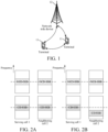
- FIG. 1 is a block diagram of a wireless communication system to which an embodiment of the present application can be applied.
- the wireless communication system includes a terminal 11 and a network side device 12.
- the terminal 11 may be a terminal side device such as a mobile phone, a tablet personal computer (Tablet Personal Computer), a laptop computer (Laptop Computer) or a notebook computer, a personal digital assistant (Personal Digital Assistant, PDA), a palmtop computer, a netbook, an ultra-mobile personal computer (ultra-mobile personal computer, UMPC), a mobile Internet device (Mobile Internet Device, MID), an augmented reality (augmented reality, AR)/virtual reality (virtual reality, VR) device, a robot, a wearable device (Wearable Device), a vehicle user equipment (Vehicle User Equipment, VUE), a pedestrian user equipment (Pedestrian User Equipment, PUE), a smart appliance (an appliance device with a wireless communication function, such as a refrigerator, a TV, a washing machine, or furniture), a
- the wearable device includes: a smart watch, a smart bracelet, smart earphones, smart glasses, smart jewelry (a smart bangle, a smart bracelet, a smart ring, a smart necklace, and a smart anklet), a smart wristband, smart clothing, and the like. It should be noted that a specific type of the terminal 11 is not limited in embodiments of the present application.
- the network side device 12 may include an access network device or a core network device.
- the access network device 12 may also be referred to as a radio access network device, a radio access network (Radio Access Network, RAN), a radio access network function, or a radio access network unit.
- RAN Radio Access Network
- the access network device 12 may include a base station, a wireless local area network (Wireless Local Area Network, WLAN) access point, or a wireless fidelity (Wireless Fidelity, Wi-Fi) node.
- the base station may be referred to as a NodeB, an evolution NodeB (eNB), an access point, a base transceiver station (Base Transceiver Station, BTS), a radio base station, a radio transceiver, a basic service set (Basic Service Set, BSS), an extended service set (Extended Service Set, ESS), a household B node, a household evolutionary B node, a transmission reception point (Transmission Reception Point, TRP), or some other suitable terms in the field, provided that the same technical effect is achieved, the base station is not limited to a particular technical term. It should be noted that, in embodiments of the present application, only a base station in the NR system is taken as an example, but a specific type of the base station is not limited.
- a terminal performs one or more of the following operations in an initial downlink bandwidth part (initial DL BWP, also referred to as a first downlink bandwidth part) of a cell: receiving a synchronization signal block, performing uplink sending in a random access process (in a corresponding initial uplink BWP (initial UL BWP)), performing downlink reception, and receiving system information and paging information.
- the terminal performs BWP switching and cell reselection judgment of radio resource management (Radio Resource Management, RRM) based on a cell defining SSB (cell defining SSB, CD SSB, also referred to as a first SSB in this specification) in the initial downlink BWP.
- RRM Radio Resource Management
- a separate initial DL BWP (also referred to as a second downlink BWP in this specification) can be configured for some terminals (for example, some types of terminals, such as a redcap UE), the terminal can perform the foregoing sending and receiving behaviors in the separate BWP.
- the separate BWP and the first downlink BWP may be completely staggered, or partially overlap, or have an inclusive relationship in frequency domain.
- the terminal Since the terminal needs to obtain downlink synchronization, BWP switching, automatic gain control (Automatic Gain Control, AGC), and other operations based on the SSB, if the separate initial DL BWP does not include the SSB, the terminal may need to frequently perform radio frequency retuning (RF retuning), that is, need to frequently return from the separate initial DL BWP to a bandwidth of the first downlink BWP for SSB reception. This may increase power consumption of the terminal, increase a probability of service interruption, and decrease system performance.
- RF retuning radio frequency retuning
- one SSB (also referred to as a second SSB in this specification, where the second SSB is the NCD SSB, namely, non-cell defining synchronization signal and PBCH block) is included in the second downlink BWP, so that the power consumption of the terminal for sending and receiving in the BWP may be reduced.
- the second SSB is usually an NCD SSB, that is, the SSB does not include an indication of system information receiving configuration.
- the terminal may determine a location and a frequency of the second SSB in the second downlink BWP based on system information in the first downlink BWP or high-level signaling, and configure the terminal to perform RRMBWP switching on a frequency of the second SSB.
- the BWP switching may be intra-frequency (intra-frequency) BWP switching, including BWP switching of a serving cell and BWP switching of an intra-frequency neighboring cell. Based on a BWP switching result, it is determined whether to enable neighboring cell BWP switching or whether to perform neighboring cell reselection on this frequency.
- the BWP switching of a serving cell is first performed.
- the BWP switching result including reference signal received power (Reference Signal Received Power, RSRP) and/or reference signal received quality (Reference Signal Received Quality, RSRQ)
- RSRP Reference Signal Received Power
- RSRQ Reference Signal Received Quality
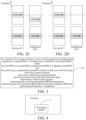
- locations of CD SSBs and NCD SSBs deployed by a network are flexible. There is not necessarily a deployment of the neighboring cell on the frequency of the CD SSB or the NCD SSB.
- frequency locations of the CD SSBs and the NCD SSBs of two cells are the same; as shown in FIG. 2B , frequencies of the NCD SSBs of two cells are the same, but frequencies of the CD SSBs are different; as shown in FIG. 2C and FIG. 2D , frequency locations of the CD SSBs of two cells are the same, but the frequency locations of the NCD SSBs are different, or there is no NCD SSB in a second cell.
- a physical cell identifier (Physical Cell Identifier, PCI) of the SSBs at different frequency locations of the same cell/carrier deployed by the network may be the same or different.
- Network deployment has greater flexibility, and the PCI is carried by a synchronization signal in the SSB
- the terminal cannot know a PCI of the first SSB associated with the second SSB with better signal quality that the BWP switches to. That is, the terminal does not know a PCI of a target reselection cell. In this case, the terminal may be unable to quickly perform reselection and/or reside in a target cell.
- transmit power and frame/slot/symbol timing of the SSBs at different frequency locations may be different. Without knowing the information, the terminal may not be able to accurately perform BWP switching or quickly complete cell reselection.
- the network may deploy the CD SSBs to some preset frequencies, and the terminal searches for a synchronization signal block on these frequencies.
- the NCD SSB may be sent after being deployed on a frequency corresponding to a sync raster (sync raster), or may be sent on a frequency of a non-sync raster.
- information in a physical broadcast channel indicates the following information, including one of the following:
- NCD SSB is deployed on the sync raster, this is not an optimal deployment, because the terminal may discover the cell through search, but cannot directly obtain system information on this frequency to access the cell. This deployment increases a cell search delay of the terminal.
- a more optimal deployment is to deploy the NCD SSB on a frequency outside the sync raster.
- the (part of) information indicated by the PBCH in the SSB is currently meaningless. Therefore, it can be considered to use indication information of the PBCH in this deployment mode to assist the terminal in determining BWP switching and reselection behaviors.
- the suitable cell at least meets all of the following conditions:
- the UE sequentially evaluates whether each frequency has a suitable target cell for reselection based on a frequency priority order starting from a high-priority frequency provided by the network. Only the suitable cell can be used as a target cell for reselection.
- Different frequencies can be configured with the same or different frequency priorities.
- an idle state protocol defines configurations related to BWP switching in an idle state and an inactive state and a BWP switching trigger condition of a neighboring cell, and further defines a configuration related to BWP switching in a connected state and a condition for BWP switching reporting.
- the UE chooses not to perform BWP switching of the intra-frequency neighboring cell. Otherwise, if it is lower than the threshold, BWP switching of the intra-frequency neighboring cell needs to be performed.
- the terminal performs BWP switching of the neighboring cell based on BWP switching requirements defined in the protocol.
- the priority is equal to or lower than the current serving frequency and the RAT, and when the serving cell meets Srxlev > SnonIntraSearchP and Squal > SnonIntraSearchQ, the UE chooses not to perform BWP switching of the neighboring cell. Otherwise, if it is lower than the threshold, BWP switching of the neighboring cell needs to be performed.
- the foregoing neighboring cell BWP switching threshold is optionally configurable on the network side.
- the threshold is defined in the protocol.
- BWP switching result of the current cell does not meet an S criterion for a plurality of times successively, BWP switching of the neighboring cell is triggered.
- the terminal When in the connected state, the terminal determines whether a BWP switching result (RSRP or RSRQ) of a special cell (Special Cell, SpCell) and a configured S-measure (S-measure) related threshold (s-MeasureConfig) meet the condition. If the BWP switching result is lower than the configured threshold, the terminal calculates and reports the BWP switching result based on the BWP switching configuration and the BWP switching reporting configuration. Therefore, when the BWP switching result is higher than the threshold, there is no need to perform corresponding BWP switching and BWP switching reporting.
- RSRP or RSRQ RSRP or RSRQ
- S-measure S-measure related threshold
- An embodiment of the present application provides a BWP switching method. As shown in FIG. 3 , the method includes:
- the terminal when the first preset condition is met, the terminal performs the predetermined operation in the second BWP or switches from the first BWP to the second BWP, so that not all terminals perform the predetermined operation in the first BWP, but some terminals are scattered to perform the predetermined operation in the second BWP.
- This can achieve load balancing on a network side.
- a RedCap terminal can perform the predetermined operation in the second BWP. This can avoid the impact of a large number of RedCap terminals on a normal terminal (the terminal that performs the predetermined operation in the first BWP).
- switching from the first BWP to the second BWP can avoid frequent radio frequency retuning of the terminal between the first BWP and the second BWP, reduce power consumption of the terminal, reduce a probability of service interruption, and avoid a system performance decrease.
- the first BWP is an initial BWP (initial BWP), including a first SSB.
- the second BWP is a separate initial BWP (separate initial BWP), including a second SSB.
- the second BWP is different from the first BWP.
- the BWP (including the first BWP and the second BWP) includes at least one of the following: an uplink UL BWP and a downlink DL BWP.
- the first SSB is a CD-SSB.
- a PBCH in the CD-SSB includes received related configuration information indicating the system information, and/or a sending frequency location of the CD-SSB is at a frequency location corresponding to the Sync raster.
- the second SSB is an NCD SSB.
- a PBCH in the NCD SSB does not include received configuration information indicating the system information, and/or a sending frequency location of the NCD SSB is not at a frequency location corresponding to the Sync raster.
- the method before the terminal performs the predetermined operation in the second BWP, or switches from the first BWP to the second BWP, the method further includes: receiving, by the terminal, configuration information of a non-cell defining synchronization signal and PBCH block NCD SSB of the second BWP from a network side device. After the configuration information of the NCD SSB is received, the terminal is configured to measure the NCD SSB by using the configuration information, and subsequent actions (the terminal performs the predetermined operation in the second BWP or switches from the first BWP to the second BWP) all need to be completed by measuring the NCD SSB.
- the method before the terminal performs the predetermined operation in the second BWP, the method further includes: performing the predetermined operation in the first BWP. In this way, after the predetermined operation is performed in the first BWP, the predetermined operation is performed in the second BWP or the second BWP is switched to. This can ensure that the predetermined operation can be performed smoothly. Even if the switching to the second BWP is not successful, the predetermined operation is already performed in the first BWP.
- the first preset condition includes at least one of the following:
- the terminal is in a center of the cell or not at an edge of the cell. In this way, when the terminal is close to or located in the center of the cell, the terminal can switch to the second BWP to perform the predetermined operation or switch to the second BWP. This can achieve load balancing on the network side, or reduce the impact on existing terminals in the first BWP.
- the terminal meets an S-measure mechanism. In this way, some terminals switch to the second BWP or terminal behaviors are switched to the second BWP. This can effectively perform load balancing on the network side, or reduce the impact on existing terminals in the first BWP.
- a condition that meets the S-measure mechanism may be: the measurement performance of the current cell is greater than a twentieth preset threshold, and the twentieth preset threshold may be configured by the network side device or agreed on in a protocol.
- the terminal does not enable neighboring cell measurement, and the neighboring cell includes at least one of the following: an intra-frequency neighboring cell, an inter-frequency neighboring cell, and an inter-system neighboring cell.
- the neighboring cell includes at least one of the following: an intra-frequency neighboring cell, an inter-frequency neighboring cell, and an inter-system neighboring cell.
- a second network side device sends the NCD SSB in the second BWP, and the second network side device is a network side device corresponding to the neighboring cell.
- the neighboring cells include some neighboring cells and all neighboring cells.
- the terminal may receive the NCD SSB sent by the second network side device, or receive a message indicating the second network side device to send the NCD SSB in the second BWP.
- the terminal performs cell selection or reselection. In this way, some terminals or terminal behaviors are switched to the second BWP. This can effectively perform load balancing on the network side, or reduce the impact on existing terminals in the first BWP.
- the terminal is in low mobility or a stationary state. In this way, some terminals or terminal behaviors are switched to the second BWP. This can effectively perform load balancing on the network side, or reduce the impact on existing terminals in the first BWP.
- a random number corresponding to the terminal is within a preset range, that is, a preset proportion of terminals perform the predetermined operation in the second BWP or switch from the first BWP to the second BWP, thereby achieving load balancing on the network side.
- the preset range is a range determined through the preset proportion. If the preset proportion is X%, the corresponding terminals generate a random number of 0-1. If the random number is less than or equal to X%, the random number corresponding to the terminals belongs to the preset range; and if the random number generated by the terminal is greater than or equal to X%, the random number corresponding to the terminal does not belong to the preset range, that is, the load control on the network side is implemented according to a specific proportion.
- a specific reference signal exists in the second BWP and the specific reference signal includes: an NCD SSB.
- the second BWP has reference signals such as an SSB, a channel state information resource indicator (Channel State Information Resource Indicator, CSI-RS), a sounding reference signal (Sounding Reference Signal, SRS), or a demodulation reference signal (Demodulation Reference Signal, DMRS)
- CSI-RS Channel State Information Resource Indicator
- SRS Sounding reference signal
- DMRS demodulation Reference Signal
- a first indication of the first network side device is received.
- the method further includes: receiving a third indication of the first network side device, where the third indication indicates the first preset condition.
- the terminal After receiving the third indication of the first network side device, the terminal performs the predetermined operation or switches from the first BWP to the second BWP.
- the first network side device may issue the third indication according to the system load, indicating the terminal to perform the predetermined operation in the second BWP to achieve load balancing.
- the first network side device may further issue the third indication to a RedCap terminal to avoid the impact of a large number of RedCap terminals on normal terminals (terminals that perform the predetermined operation in the first BWP).
- the first indication indicates at least one of the following:
- the R criterion for cell reselection is to rank the measurement performance of the neighboring cell, or the measurement performance of the current cell and the neighboring cell, and select a cell with the best measurement performance as a target cell.
- the measurement performance of the NCD SSB of the second BWP is used as the measurement performance of the corresponding cell.
- the S criterion for cell selection and reselection may include: the measurement performance of the target cell is higher than a preset threshold 1; or the measurement performance of the target cell is higher than a preset threshold 1, and the measurement performance of the current cell is lower than a preset threshold 2.
- the preset threshold 1 and the preset threshold 2 may be determined based on actual requirements.
- the measurement performance of the NCD SSB of the second BWP is used as the measurement performance of the corresponding cell.
- that the terminal is in low mobility or a stationary state includes at least one of the following:
- the first indication is sent through a radio resource control (Radio Resource Control, RRC) message;
- the first indication is sent through at least one of the following messages: the broadcast system message, the paging message, the paging advance indication message, and the dedicated RRC message, where the paging message includes a physical downlink shared channel (Physical Downlink Shared Channel, PDSCH) and/or a downlink control information (Downlink Control Information, DCI) corresponding to a physical downlink control channel (Physical Downlink Control Channel, PDCCH), and the dedicated RRC message includes an RRC release (release) message, an RRC suspend (suspend) message, and an RRC reject (reject) message.
- the paging message includes a physical downlink shared channel (Physical Downlink Shared Channel, PDSCH) and/or a downlink control information (Downlink Control Information, DCI) corresponding to a physical downlink control channel (Physical Downlink Control Channel, PDCCH)
- the dedicated RRC message includes an RRC release (release) message, an RRC suspend (suspend) message, and an RRC reject (re
- the configuration information of the NCD SSB or the second BWP includes at least one of the following:
- the method further includes: in a case that a second preset condition is met, performing the predetermined operation in the first BWP, or switching from the second BWP to the first BWP.
- the terminal when the second preset condition is met, the terminal performs the predetermined operation in the first BWP or switches from the second BWP to the first BWP, so that not all terminals perform the predetermined operation in the second BWP, but some terminals are scattered to perform the predetermined operation in the first BWP.
- This can achieve load balancing on a network side.
- switching from the second BWP to the first BWP can avoid frequent radio frequency retuning of the terminal between the first BWP and the second BWP, reduce power consumption of the terminal, reduce a probability of service interruption, and avoid a system performance decrease.
- the second preset condition includes at least one of the following:
- that the terminal is in medium to high mobility includes at least one of the following:
- the second indication indicates at least one of the following:
- the second indication in a case that the terminal is in the connected state, the second indication is sent through the RRC message; and in a case that the terminal is in the idle state or the inactive state, the second indication is sent through at least one of the following messages: the broadcast system message, the paging message, the paging advance indication message, and the dedicated RRC message.
- the paging message includes a downlink control information DCI corresponding to the PDSCH and/or the PDCCH
- the dedicated RRC message includes an RRC release (release) message, an RRC suspend (suspend) message, and the like.
- the BWP switching method provided in this embodiment of the present application may be performed by a BWP switching apparatus.
- a BWP switching apparatus In this embodiment of the present application, an example in which the BWP switching apparatus performs the BWP switching method is used to illustrate the BWP switching apparatus provided in this embodiment of the present application.
- An embodiment of the present application provides a BWP switching apparatus, as shown in FIG. 4 , including:
- the apparatus is used in the terminal.
- the terminal when the first preset condition is met, the terminal performs the predetermined operation in the second BWP or switches from the first BWP to the second BWP, so that not all terminals perform the predetermined operation in the first BWP, but some terminals are scattered to perform the predetermined operation in the second BWP.
- This can achieve load balancing on a network side.
- a RedCap terminal can perform the predetermined operation in the second BWP. This can avoid the impact of a large number of RedCap terminals on a normal terminal (the terminal that performs the predetermined operation in the first BWP).
- switching from the first BWP to the second BWP can avoid frequent radio frequency retuning of the terminal between the first BWP and the second BWP, reduce power consumption of the terminal, reduce a probability of service interruption, and avoid a system performance decrease.
- the apparatus further includes: a receiving module, configured to receive, by the terminal, configuration information of a non-cell defining synchronization signal and PBCH block NCD SSB of the second BWP from a network side device.
- a receiving module configured to receive, by the terminal, configuration information of a non-cell defining synchronization signal and PBCH block NCD SSB of the second BWP from a network side device.
- the processing module is further configured to perform the predetermined operation in the first BWP.
- the first preset condition includes at least one of the following:
- the receiving module is further configured to receive a third indication of the first network side device, where the third indication indicates the first preset condition.
- the first indication indicates at least one of the following:
- the bandwidth of the terminal includes at least one of the following:
- the carrier bandwidth, the channel bandwidth, or the system bandwidth is configured by the network side device or agreed on in a protocol.
- that the terminal is in low mobility or a stationary state includes at least one of the following:
- the first indication in a case that the terminal is in a connected state, the first indication is sent through a radio resource control RRC message; and in a case that the terminal is in an idle state or an inactive state, the first indication is sent through at least one of the following messages: a broadcast system message, a paging message, a paging advance indication message, and a dedicated RRC message.
- a radio resource control RRC message in a case that the terminal is in a connected state, the first indication is sent through a radio resource control RRC message; and in a case that the terminal is in an idle state or an inactive state, the first indication is sent through at least one of the following messages: a broadcast system message, a paging message, a paging advance indication message, and a dedicated RRC message.
- the configuration information of the NCD SSB or the second BWP includes at least one of the following:
- the processing module is further configured to in a case that a second preset condition is met, perform the predetermined operation in the first BWP, or switch from the second BWP to the first BWP.
- the second preset condition includes at least one of the following:
- that the terminal is in medium to high mobility includes at least one of the following:
- the second indication indicates at least one of the following:
- the second indication in a case that the terminal is in the connected state, the second indication is sent through the RRC message; and in a case that the terminal is in the idle state or the inactive state, the second indication is sent through at least one of the following messages: the broadcast system message, the paging message, the paging advance indication message, and the dedicated RRC message.
- the BWP switching apparatus in this embodiment of the present application may be an electronic device, such as an electronic device with an operating system, or may be a component in the electronic device, such as an integrated circuit or chip.
- the electronic device may be a terminal or other devices other than the terminal.
- the terminal may include, but is not limited to, the types of terminal 11 listed above, and the other devices may be a server, a network attached storage (Network Attached Storage, NAS), and the like, and embodiments of the present application are not specifically limited.
- Network Attached Storage Network Attached Storage
- the BWP switching apparatus provided in embodiments of the present application can implement all processes implemented by the method embodiments of FIG. 3 , and the same technical effects are achieved. To avoid repetition, details are not described herein again.
- an embodiment of the present application further provides a communication device 600, including a processor 601 and a memory 602, and the memory 602 stores a program or instructions run on the processor 601.
- the communication device 600 is a terminal
- the program or the instructions when executed by the processor 601, implements all steps of the foregoing BWP switching method embodiments, and the same technical effects can be achieved. To avoid repetition, details are not described herein again.
- An embodiment of the present application further provides a terminal.
- the terminal includes a processor and a memory, the memory storing a program or instructions run on the processor, the program or the instructions, when executed by the processor, implementing steps of the BWP switching method above
- An embodiment of the present application further provides a terminal, including a processor and a communication interface, where the processor is configured to in a case that a first preset condition is met, perform a predetermined operation in a second BWP, or switch from a first BWP to the second BWP, where
- An embodiment of the present application further provides a terminal, including a processor and a communication interface.
- the terminal embodiment corresponds to the above terminal side method embodiment, and the various implementation processes and implementations of the above method embodiments can be applied to the terminal embodiment, and can achieve the same technical effect.
- FIG. 6 is a schematic diagram of a hardware structure of a terminal that implements embodiments of the present application.
- the terminal 700 includes, but is not limited to: at least some components such as a radio frequency unit 701, a network module 702, an audio output unit 703, an input unit 704, a sensor 705, a display unit 706, a user input unit 707, an interface unit 708, a memory 709, and a processor 710.
- the terminal 700 further includes a power supply (such as a battery) for supplying power to the components.
- the power supply may logically connect to the processor 710 by using a power supply management system, thereby implementing functions, such as charging, discharging, and power consumption management, by using the power supply management system.
- a terminal structure shown in FIG. 6 does not constitute a limitation to the terminal, and the terminal may include more or fewer components than those shown in the figure, or some components may be combined, or a different component deployment may be used. Details are not described herein again.
- the input unit 704 may include a graphics processing unit (Graphics Processing Unit, GPU) 7041 and a microphone 7042.
- the graphics processing unit 7041 performs processing on image data of a static picture or a video that is obtained by an image acquisition apparatus (for example, a camera) in a video acquisition mode or an image acquisition mode.
- the display unit 706 may include a display panel 7061, for example, the display panel 7061 may be configured in a form such as a liquid crystal display or an organic light-emitting diode.
- the user input unit 707 includes at least one of a touch panel 7071 and another input device 7072.
- the touch panel 7071 is also referred to as a touch screen.
- the touch panel 7071 may include two parts: a touch detection apparatus and a touch controller.
- the another input device 7072 may include, but is not limited to, a physical keyboard, a functional key (such as a volume control key or a switch key), a track ball, a mouse, and a joystick, and details are not described herein again.
- the radio frequency unit 701 receives downlink data from a network side device and then transmits the downlink data to the processor 710 for processing.
- the radio frequency unit 701 may send uplink data to the network side device.
- the radio frequency unit 701 includes, but is not limited to, an antenna, an amplifier, a transceiver, a coupler, a low noise amplifier, a duplexer, and the like.
- the memory 709 may be configured to store a software program or instructions and various data.
- the memory 709 may mainly include a first storage region for storing the program or the instructions and a second storage region for storing data.
- the first storage region may store an operating system, an application program or instructions required by at least one function (for example, a sound playback function and an image playback function), or the like.
- the memory 709 may include a volatile memory or a non-volatile memory, or the memory 709 may include both a volatile memory and a non-volatile memory.
- the non-volatile memory may be a read-only memory (Read-Only Memory, ROM), a programmable ROM (Programmable ROM, PROM), an erasable PROM (Erasable PROM, EPROM), an electrically EPROM (Electrically EPROM, EEPROM), or a flash memory.
- ROM Read-Only Memory
- PROM programmable ROM
- PROM erasable PROM
- EPROM Erasable PROM
- EEPROM Electrically EPROM
- the volatile memory may be a random access memory (Random Access Memory, RAM), a static RAM (Static RAM, SRAM), a dynamic RAM (Dynamic RAM, DRAM), a synchronous DRAM (Synchronous DRAM, SDRAM), a double data rate SDRAM (Double Data Rate SDRAM, DDR SDRAM), an enhanced SDRAM (Enhanced SDRAM, ESDRAM), a synch link DRAM (Synch link DRAM, SLDRAM), and a direct rambus RAM (Direct Rambus RAM, DRRAM).
- RAM Random Access Memory
- SRAM static RAM
- DRAM dynamic RAM
- DRAM synchronous DRAM
- SDRAM Double data rate SDRAM
- ESDRAM enhanced SDRAM
- synch link DRAM Synch link DRAM
- SLDRAM synch link DRAM
- DRRAM direct Rambus RAM
- the processor 710 may include one or more processing units.
- the processor 710 integrates an application processor and a modem processor.
- the application processor mainly processes operations related to an operating system, a user interface, and an application program.
- the modem processor mainly processes a wireless communication signal, such as a baseband processor. It may be understood that the modem processor may not be integrated into the processor 710.
- the processor 710 is configured to in a case that a first preset condition is met, perform a predetermined operation in a second BWP, or switch from a first BWP to the second BWP, where
- the processor 710 is configured to receive configuration information of a non-cell defining synchronization signal and PBCH block NCD SSB of the second BWP from a network side device.
- the processor 710 is configured to perform the predetermined operation in the first BWP.
- the first preset condition includes at least one of the following:
- the processor 710 is configured to receive a third indication of the first network side device, where the third indication indicates the first preset condition.
- the first indication indicates at least one of the following:
- the bandwidth of the terminal includes at least one of the following:
- the carrier bandwidth, the channel bandwidth, or the system bandwidth is configured by the network side device or agreed on in a protocol.
- that the terminal is in low mobility or a stationary state includes at least one of the following:
- the first indication in a case that the terminal is in a connected state, the first indication is sent through a radio resource control RRC message; and in a case that the terminal is in an idle state or an inactive state, the first indication is sent through at least one of the following messages: a broadcast system message, a paging message, a paging advance indication message, and a dedicated RRC message.
- a radio resource control RRC message in a case that the terminal is in a connected state, the first indication is sent through a radio resource control RRC message; and in a case that the terminal is in an idle state or an inactive state, the first indication is sent through at least one of the following messages: a broadcast system message, a paging message, a paging advance indication message, and a dedicated RRC message.
- the configuration information of the NCD SSB or the second BWP includes at least one of the following:
- the processor 710 is configured to in a case that a second preset condition is met, perform the predetermined operation in the first BWP, or switch from the second BWP to the first BWP.
- the second preset condition includes at least one of the following:
- that the terminal is in medium to high mobility includes at least one of the following:
- the second indication indicates at least one of the following:
- the second indication in a case that the terminal is in the connected state, the second indication is sent through the RRC message; and in a case that the terminal is in the idle state or the inactive state, the second indication is sent through at least one of the following messages: the broadcast system message, the paging message, the paging advance indication message, and the dedicated RRC message.
- An embodiment of the present application further provides a readable storage medium, storing a program or instructions.
- the program or the instructions when executed by a processor, implements all processes of the foregoing BWP switching method embodiments, and can achieve the same technical effects. To avoid repetition, details are not described herein again.
- the processor is a processor in the terminal in the foregoing embodiments.
- the readable storage medium includes a computer-readable storage medium, for example, a computer read-only memory ROM, a random access memory RAM, a magnetic disk, or an optical disc.
- An embodiment of the present application further provides a chip, including a processor and a communication interface, where the communication interface is coupled to the processor, and the processor is configured to run a program or instructions, to implement all processes of the foregoing BWP switching method embodiments, and can achieve the same technical effects. To avoid repetition, details are not described herein again.
- the chip described in embodiments of the present application may also be referred to as a system-level chip, a system chip, a chip system, a system on chip, or the like.
- An embodiment of the present application further provides a computer program product, where the computer program product is stored in a storage medium and executed by at least one processor to implement all processes of the foregoing BWP switching method embodiments, and can achieve the same technical effects. To avoid repetition, details are not described herein again.
- An embodiment of the present application further provides a BWP switching system.
- the system includes: a network side device and a terminal, and the terminal may be configured to perform steps of the BWP switching method above.
- the computer software product is stored in a storage medium (for example, a ROM/RAM, a magnetic disk, or an optical disc), and includes several instructions for instructing a terminal (which may be a mobile phone, a computer, a server, an air conditioner, a network device, or the like) to perform the method described in embodiments of the present application.
- a storage medium for example, a ROM/RAM, a magnetic disk, or an optical disc
- a terminal which may be a mobile phone, a computer, a server, an air conditioner, a network device, or the like
Landscapes
- Engineering & Computer Science (AREA)
- Computer Networks & Wireless Communication (AREA)
- Signal Processing (AREA)
- Computer Security & Cryptography (AREA)
- Mobile Radio Communication Systems (AREA)
Applications Claiming Priority (2)
| Application Number | Priority Date | Filing Date | Title |
|---|---|---|---|
| CN202111627146.5A CN116367247A (zh) | 2021-12-28 | 2021-12-28 | Bwp切换方法及装置、终端 |
| PCT/CN2022/141051 WO2023125236A1 (zh) | 2021-12-28 | 2022-12-22 | Bwp切换方法及装置、终端 |
Publications (2)
| Publication Number | Publication Date |
|---|---|
| EP4460069A1 true EP4460069A1 (de) | 2024-11-06 |
| EP4460069A4 EP4460069A4 (de) | 2025-08-27 |
Family
ID=86925441
Family Applications (1)
| Application Number | Title | Priority Date | Filing Date |
|---|---|---|---|
| EP22914490.2A Pending EP4460069A4 (de) | 2021-12-28 | 2022-12-22 | Verfahren und vorrichtung zum bwp-umschalten und endgerät |
Country Status (4)
| Country | Link |
|---|---|
| US (1) | US20240340735A1 (de) |
| EP (1) | EP4460069A4 (de) |
| CN (1) | CN116367247A (de) |
| WO (1) | WO2023125236A1 (de) |
Families Citing this family (3)
| Publication number | Priority date | Publication date | Assignee | Title |
|---|---|---|---|---|
| CN116567673B (zh) * | 2023-07-07 | 2023-11-03 | 翱捷科技股份有限公司 | 一种RedCap终端接入网络的优化方法及装置 |
| WO2025129588A1 (en) * | 2023-12-21 | 2025-06-26 | Nokia Shanghai Bell Co., Ltd. | Autonomous bandwidth part switch |
| CN120201539A (zh) * | 2023-12-22 | 2025-06-24 | 维沃移动通信有限公司 | Ssb传输方法、装置、通信设备及存储介质 |
Family Cites Families (6)
| Publication number | Priority date | Publication date | Assignee | Title |
|---|---|---|---|---|
| WO2019099817A1 (en) * | 2017-11-16 | 2019-05-23 | Ofinno, Llc | Channel state information report on bandwidth part |
| EP3547559B1 (de) * | 2018-03-30 | 2024-08-14 | Comcast Cable Communications LLC | Strahlausfallwiederherstellungsverfahren unter verwendung von bandbreitenteilen |
| EP4068896A1 (de) * | 2018-08-06 | 2022-10-05 | Samsung Electronics Co., Ltd. | Zellen- und bandbreitenteiloperationen in unlizenzierten bändern |
| US11877242B2 (en) * | 2018-10-17 | 2024-01-16 | Beijing Xiaomi Mobile Software Co., Ltd. | Bandwidth part switching method and apparatus |
| CN111556536B (zh) * | 2019-02-11 | 2021-10-01 | 华为技术有限公司 | Bwp切换方法及通信装置 |
| US11245510B2 (en) * | 2019-05-02 | 2022-02-08 | Ofinno, Llc | Beam failure recovery procedure for bandwidth parts |
-
2021
- 2021-12-28 CN CN202111627146.5A patent/CN116367247A/zh active Pending
-
2022
- 2022-12-22 EP EP22914490.2A patent/EP4460069A4/de active Pending
- 2022-12-22 WO PCT/CN2022/141051 patent/WO2023125236A1/zh not_active Ceased
-
2024
- 2024-06-17 US US18/745,145 patent/US20240340735A1/en active Pending
Also Published As
| Publication number | Publication date |
|---|---|
| WO2023125236A1 (zh) | 2023-07-06 |
| EP4460069A4 (de) | 2025-08-27 |
| US20240340735A1 (en) | 2024-10-10 |
| CN116367247A (zh) | 2023-06-30 |
Similar Documents
| Publication | Publication Date | Title |
|---|---|---|
| US20240179684A1 (en) | Random access resource selection method and apparatus, random access resource configuration method and apparatus, terminal, and network side device | |
| US12519587B2 (en) | Method for measuring reference signal, terminal, and network side device | |
| EP4460069A1 (de) | Verfahren und vorrichtung zum bwp-umschalten und endgerät | |
| EP4510701A1 (de) | Zellumschaltungsverfahren, zellumschaltungskonfigurationsverfahren und -vorrichtung, endgerät und netzwerkseitige vorrichtung | |
| EP3065443A1 (de) | Messkonfigurationsverfahren, identifizierungs- und messverfahren, makrobasisstation und benutzergerät | |
| EP4213546A1 (de) | Netzwerkzugangsverfahren, netzwerkzugangsvorrichtung, endgerät und netzwerkseitige vorrichtung | |
| EP4460082A1 (de) | Verfahren und vorrichtung zur zellenauswahl oder -neuauswahl, endgerät und lesbares speichermedium | |
| US20250220531A1 (en) | Cell selection and/or reselection method and apparatus | |
| CN115278787A (zh) | 移动性管理的配置方法、装置、终端、网络侧设备及介质 | |
| WO2019167844A1 (ja) | ユーザ装置 | |
| WO2023004965A1 (zh) | 邻区测量方法及装置 | |
| EP4224908A1 (de) | Verfahren und vorrichtung zur zellauswahl/-neuauswahl, endgerät und lesbares speichermedium | |
| US20250159492A1 (en) | Measurement control method, terminal, and network side device | |
| US20250380329A1 (en) | Configuration method and apparatus, device, and readable storage medium | |
| US20240349213A1 (en) | Measurement method and apparatus, and terminal | |
| US20230232295A1 (en) | Method for changing working area, terminal, and network-side device | |
| EP4383815A1 (de) | Verfahren und vorrichtung zur bestimmung eines niedrigen mobilitätszustands, endgerät und netzwerkseitige vorrichtung | |
| WO2023125237A1 (zh) | 小区选择或重选方法、装置、终端及可读存储介质 | |
| EP4557811A1 (de) | Messverfahren und -vorrichtung sowie vorrichtung | |
| US20240365180A1 (en) | Cell Reselection Method and Apparatus, Device, System, and Storage Medium | |
| US20250380310A1 (en) | Small data transmission method and apparatus, terminal, and network side device | |
| WO2025007900A1 (zh) | Lp-wus的监听方法、终端及网络侧设备 | |
| WO2024165003A1 (zh) | 条件切换方法、装置、终端及网络侧设备 | |
| WO2026040900A1 (zh) | 移动性管理方法、装置、终端及网络侧设备 | |
| CN120128943A (zh) | 无线通信方法、装置及设备 |
Legal Events
| Date | Code | Title | Description |
|---|---|---|---|
| STAA | Information on the status of an ep patent application or granted ep patent |
Free format text: STATUS: THE INTERNATIONAL PUBLICATION HAS BEEN MADE |
|
| PUAI | Public reference made under article 153(3) epc to a published international application that has entered the european phase |
Free format text: ORIGINAL CODE: 0009012 |
|
| STAA | Information on the status of an ep patent application or granted ep patent |
Free format text: STATUS: REQUEST FOR EXAMINATION WAS MADE |
|
| 17P | Request for examination filed |
Effective date: 20240523 |
|
| AK | Designated contracting states |
Kind code of ref document: A1 Designated state(s): AL AT BE BG CH CY CZ DE DK EE ES FI FR GB GR HR HU IE IS IT LI LT LU LV MC ME MK MT NL NO PL PT RO RS SE SI SK SM TR |
|
| DAV | Request for validation of the european patent (deleted) | ||
| DAX | Request for extension of the european patent (deleted) | ||
| REG | Reference to a national code |
Ref country code: DE Ref legal event code: R079 Free format text: PREVIOUS MAIN CLASS: H04W0024000000 Ipc: H04W0074080000 |
|
| A4 | Supplementary search report drawn up and despatched |
Effective date: 20250729 |
|
| RIC1 | Information provided on ipc code assigned before grant |
Ipc: H04W 74/08 20240101AFI20250723BHEP Ipc: H04W 48/08 20090101ALI20250723BHEP Ipc: H04W 24/00 20090101ALI20250723BHEP Ipc: H04W 36/06 20090101ALI20250723BHEP Ipc: H04W 36/08 20090101ALI20250723BHEP Ipc: H04W 36/16 20090101ALI20250723BHEP Ipc: H04W 68/02 20090101ALI20250723BHEP Ipc: H04W 56/00 20090101ALI20250723BHEP |